EP2161560A2 - Procédé de commande d'un banc d'essai de transmissions de puissance de véhicules - Google Patents
Procédé de commande d'un banc d'essai de transmissions de puissance de véhicules Download PDFInfo
- Publication number
- EP2161560A2 EP2161560A2 EP09167059A EP09167059A EP2161560A2 EP 2161560 A2 EP2161560 A2 EP 2161560A2 EP 09167059 A EP09167059 A EP 09167059A EP 09167059 A EP09167059 A EP 09167059A EP 2161560 A2 EP2161560 A2 EP 2161560A2
- Authority
- EP
- European Patent Office
- Prior art keywords
- vehicle
- wheels
- wheel
- determined
- ist
- Prior art date
- Legal status (The legal status is an assumption and is not a legal conclusion. Google has not performed a legal analysis and makes no representation as to the accuracy of the status listed.)
- Withdrawn
Links
Images

Classifications
-
- G—PHYSICS
- G01—MEASURING; TESTING
- G01M—TESTING STATIC OR DYNAMIC BALANCE OF MACHINES OR STRUCTURES; TESTING OF STRUCTURES OR APPARATUS, NOT OTHERWISE PROVIDED FOR
- G01M13/00—Testing of machine parts
- G01M13/02—Gearings; Transmission mechanisms
- G01M13/025—Test-benches with rotational drive means and loading means; Load or drive simulation
Definitions
- the invention relates to a method for operating a test bench for vehicle drive trains according to the type defined in more detail in the preamble of patent claim 1,
- a test stand for testing a drive train of a vehicle from the internal combustion engine to the drive axles is known.
- Inertia moments, spring stiffnesses and damping dimensions are simulated by means of electronic functional elements or by means of a computer, wherein torque-controlled electrical loading machines serve as transmission elements between the electronic functional elements or the computer and the test stand with the test object. At least two independent loading machines are flanged directly to the shafts of the drive train to be tested.
- the vehicle resistance torque reduced by the wheel torques is fed to a first integrator with a time constant proportional to the vehicle moment of inertia, wherein the angular velocity proportional to the vehicle speed can be tapped off at the first integrator.
- the tire slip occurring in addition to the vehicle longitudinal dynamics is taken into account as a function of the current wheel torques.
- a control or simulation system for simulating the influence of vehicle mass and driving resistance.
- the balance of forces on the vehicle is integrated, wherein the result of this simulation is a target speed of the vehicle or a proportional thereto target speed of the loading machines, which is set via a speed control of the test bench.
- tire slip or wheel slip In real vehicles, there is always a difference between the speed proportional to the vehicle speed and the actual speed of the wheels during the transmission of a force between the drive wheels and a road, which is normally referred to as so-called tire slip or wheel slip.
- the occurring wheel slip is at in the EP 0 338 373 B1 proposed simulation substitutes that is added to the resulting from the vehicle longitudinal dynamics vehicle speed or to the proportional speed dependent on the measured actual torque percentage slip.
- This percentage slip value is determined from characteristics that assign a fixed percentage slip to a measured actual torque, and this procedure is performed separately for each wheel of the drive train.
- the resulting speed setpoint is finally adjusted via the speed control of the test bench.
- the dynamic behavior of the wheels is taken into account via the damping and stiffness parameters of the wheels in the control parameters of the speed controller.
- operating states with quasi-stationary tire slip can be simulated with sufficient accuracy
- operating state characteristics which are characterized by rapid dynamic changes and extreme driving situations, such as suddenly spinning wheels, are simulated by the maximum torque of the loading machines or the manipulated variable of the speed controller is limited to the maximum transmissible torque at given wheel and road parameters.
- the speed control is no longer active or ineffective during this procedure, so during simulation of an operating condition of a vehicle driveline with spinning wheels no corresponding speed setpoint is calculated, or is no longer computable, since this section is not specifiable as a function of the actual torque and therefore also not stored in the system.
- the EP 1 037 030 B1 another system, namely the system of torque control of the loading machine with the calculation of the measured wheel speeds.
- the wheel speed is measured, from which the tire model, using a vehicle speed and a tire tread force, transmits a force transmitted from the tire at that wheel speed to the road and a desired torque for the torque-controlled load machine attached to that shaft determines that between a nominal speed value corresponding to the vehicle speed supplied to the tire model, which is calculated by returning the force transmitted to the roadway in the vehicle model, and the measured wheel speed, a difference corresponding to the real occurring slip.
- the present invention has for its object to provide a method for operating a test bed for vehicle drive trains available by means of which a realistic replica of the dynamic behavior of a drive train of a vehicle with different road surfaces and road profiles, especially the simulation of spinning wheels, with high control stability and low tax and regulatory burden is feasible.
- the desired value of the rotational speed of the electric machine can already be limited during the setpoint calculation to the extent that in the area of the electrical machines no impermissibly high rotational speeds occur during the simulation. This is a simple way to operate a test bench without additional facilities for speed limitation, such as speed control knob or the like, cost and with less control effort.
- the speed setpoint values of the wheels or of the electrical machines can be used as input variables for the tire model by calculating the speed setpoints of the electrical machines via the simulation system.
- the wheels of a vehicle are always fully integrated in the simulation, which in vehicle drive trains with only one drivable vehicle axle, such as rear or front drives, or when operating as Achsgetriebeprüfstand, the unassembled vehicle axles in terms of their speed and lateral dynamic behavior without operation and real co-rotation of the associated machines are considered.
- the method according to the invention for operating a test stand is suitable both for vehicle drive trains which are designed with one, two or even several drivable vehicle axles, such as four-wheel drive vehicles or the like.
- vehicle drive trains which are designed with one, two or even several drivable vehicle axles, such as four-wheel drive vehicles or the like.
- the method according to the invention offers in a simple and cost-effective manner the possibility of realistically simulating the dynamic behavior of a drive train of a vehicle on different road surfaces and in the presence of different roadway profiles and, moreover, taking into account factors which have an influence on the behavior of the drive train during a simulation Due to the feasible in the field of the tire model replica of the tire slip loads occurring in the vehicle drive train, for example, during a spin or a blockage of wheels of a vehicle drive train, such as during driving over ice sheets, realistically simulated.
- the metrologically determined actual torques of the shafts of the drivable vehicle axle are added to the manipulated variable of a speed controller of the speed control during the disturbance variable control, while in the desired value precontrol the gradient of the nominal values of the rotational speeds of the electrical machines with the Inertia moments of the electrical machines are multiplied and added to the manipulated variable of the speed controller in order, in particular during operating state profiles of vehicle drive trains or vehicles that are characterized by high dynamics, the real Vehicle behavior and the performance of the wheels of the drive train to represent as accurately as possible.
- the setpoint values of the rotational speeds of the electric machine are determined in a variant of the method according to the invention by integration of resulting torque values of each wheel, wherein the resulting torque values for each of the wheels of the drivable vehicle axle from a difference between the metrologically determined actual torque of the corresponding shaft and a determined via the tire model, transmitted via a wheel, calculated torque value can be determined.
- a vehicle behavior on the test bench is particularly realistic replicable.
- a simulation of a vehicle behavior which is as realistic as possible is achieved by means of the method according to the invention, in which the speed of the electric machine, which is equivalent to the setpoint speed of the wheel to be imaged by the electric machine, is achieved as a function of the nominal value.
- the respective torque transmitted via a wheel is determined by multiplying the longitudinal and / or transverse forces by a dynamic wheel radius, with which the calculated torque value has a large correspondence with a real transmittable torque value.
- a simulated braking torque which is generated, for example, by friction or by a vehicle brake, a generator-operated electric machine or the like is introduced into the vehicle drive train.
- a constant flowing into the integrative determination of the resulting wheel speed setpoints is determined in a further advantageous variant of the method according to the invention in each case as a function of wheel moments of inertia to be imaged in the region of the electric machine, whereby arbitrary wheel sizes can be simulated on the test bench without conversion of mechanical masses.
- the moment of inertia of the electric machine corresponds at least approximately to the moment of inertia of the wheel of the drivable vehicle axle to be imaged by the electric machine.
- the speed of the vehicle is determined as a function of the determined via the tire model of the longitudinal forces of the wheels of the drivable vehicle axle and in dependence on operating state-dependent driving resistances by integration.
- Dynamic changes in the wheel contact forces of the wheels of the vehicle drive train caused by pitching and rolling of the vehicle are taken into account as a function of predeterminable longitudinal and lateral accelerations of the vehicle and of the terrain in the illustration of the operating behavior of the wheels of the vehicle drive train in a further advantageous variant of the method according to the invention.
- a further variant of the method takes into account for the simulation of cornering real forces acting on the wheels of the vehicle, the be determined by means of the tire model depending on the given slip angle of the wheels.
- lateral forces acting on the wheels of a vehicle are supplied as input variables to a vehicle model setting an operating behavior of the vehicle, a float angle and a yaw rate of the vehicle being determined as a function of a steering angle and various vehicle parameters by means of the vehicle model.
- a vehicle drive train 1 of an all-wheel vehicle which comprises two drivable vehicle axles 2, 3.
- the drivable vehicle axle 2 represents the vehicle front axle
- the drivable vehicle axle 3 represents the vehicle rear axle.
- a torque generated by a drive machine 4 embodied here as an internal combustion engine is transmitted via a transmission device 5 representing a main transmission of the vehicle drive train 1, which may have any conventional transmission design known from practice, and a device arranged between the transmission device 5 and the two vehicle axles 2 and 3 for distributing the torque of the engine 4 between the two drive axles 2 and 3 forwarded.
- the device 6 in the present case is designed as a longitudinal differential and can also have another suitable design for distributing the torque of the drive machine 4 with a fixed distribution factor or a continuously variable distribution factor, depending on the particular application at hand.
- the guided in the vehicle longitudinal direction to the vehicle axles 2 and 3 torque is in the region of a Vorderachsdifferentials 7 and a Schuashsdifferentials 8 in the vehicle transverse direction in equal parts in the direction of a right and in the direction of a left vehicle side on shafts 2A, 2B of the vehicle front axle 2 and Wellen 3A, 3B of the vehicle rear axle 3 forwarded.
- the shafts 2A, 28 of the vehicle front axle 2 and the shafts 3A, 3B of the vehicle rear axle 3 are operatively connected to the vehicle with wheels of the vehicle, whereby the torque provided by the engine 4 in dependence of the translations of the transmission device 5, the device 6, the Vorderachsdifferentials 7 and the rear axle 8 in a correspondingly changed height as the output torque in the range of the waves 2A to 3B is applied.
- the vehicle drive train 1 embodied without wheels here is coupled in each case to electrical machines 9 to 12 whose mass moment of inertia substantially corresponds to the mass moment of inertia of the wheels of the vehicle drive train 1 to be simulated via a test stand 13.
- the electric machines 9 to 12 are both motorized and regenerative in a so-called four-quadrant operation operable, the realistic replica of the dynamic behavior of the vehicle drive train 1 at different road surfaces and road profiles on a in Fig. 2 and Fig. 3 closer illustrated simulation system 14 of the test bed 13 is feasible.
- the electric machines 9 to 12 are coupled through the wheels in the required manner with the shafts 2A to 3B.
- a system with an electric motor drive or a system with a hybrid drive can be used.
- About the simulation system 14 are basically all factors that have an influence on the behavior of the vehicle drive train 1, considered and taken into account.
- the replica of the tire slip the wheels of the vehicle drive train 1 and also the spinning or blocking of the wheels, in particular on ice sheets possible, while occurring loads in the range of the vehicle drive train 1 can be simulated realistically.
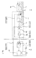
- the simulation system 14 of the test rig 13 is in Fig. 2 in the form of a simplified functional diagram shown in more detail.
- the simulation system 14 comprises a so-called vehicle model, which in Fig. 2 graphically represented by a first functional block FB1.
- the vehicle model is supplied with operating parameters characterizing the current operating state of a vehicle, such as a currently traveled road profile, such as a slope or a gradient, a driven road curve, an airspeed and the like.
- operating parameters characterizing the current operating state of a vehicle, such as a currently traveled road profile, such as a slope or a gradient, a driven road curve, an airspeed and the like.
- vehicle model also vehicle parameters, such as a total vehicle weight, geometric dimensions, inertia and suspension parameters for a total vehicle simulation are fed as input variables.
- the vehicle model supplies a vehicle speed v_fzg and tire contact forces F_z, which represent input variables of a tire model of a second function block FB2.
- a behavior of the wheels during the simulation of the behavior of the vehicle drive train 1 is shown, wherein in the region of the tire model, a coefficient of friction of the wheels of the vehicle drive train 1 on the tire slip and additional dynamic changes in the performance of the wheels of the vehicle drive train 1 depending on tire parameters, such a diameter and stiffnesses and elasticities of the tires as well as temperature-dependent tire parameters and the like may be taken into account.
- the tire as well as temperature-dependent tire parameters and the like.
- Both longitudinal forces F_x and transverse forces F_y in the area of the footprint of the wheels of the vehicle drive train 1 are calculated via the tire model and fed to the vehicle model of the first functional block FB1 as input variables.
- the rolling resistance can be determined via the tire model.
- the longitudinal forces F_x of the wheels in a third functional block FB3 of the simulation system 14 are multiplied by the dynamic wheel radius of the wheels of the vehicle drivetrain 1 and actual torques m_act_2A, m_act_2B, m_act_3A and m_jst_3B respectively measured via torque measuring flanges 2A1 and 2B1 or 3A1 and 3B1 Waves 2A to 3B are added, whereby a resulting torque value is determined for each of the wheels,
- braking torques m_B_2A to m_B_3B of the respective wheel are considered by addition in the determination of the resulting torque values.
- the resultant torque values determined for each of the wheels are fed to a fourth function block FB4 as an input quantity and multiplied by a constant, which results in each case from the wheel moments of inertia of the wheels to be simulated, and then fed again to an integrator of a fifth function block FB5 as an input variable.
- the fifth function block FB5 supplies for each of the electric machines 9 to 12 as output value a speed setpoint value n_set_2A to n_set_3B, the speed setpoint values n_set_2A to n_set_3B for both the second function block FB2 as well as for a sixth function block FB6 input values represent.
- n_soll_2A to n_soll_3B of the rotational speeds of the electrical machines 9 to 12 actual values n_actual_2A to n_act_3B of the rotational speeds of the electrical machines 9 to 12 likewise represent input values of the sixth functional block FB6, which Fig. 2 the speed controller of the electric machines 9 to 12 reproduces Grapfisch.
- the sixth function block FB6 outputs, depending on the setpoints n_soll_2A to n_soll_38 of the rotational speeds of the electrical machines 9 to 12, the manipulated variables for current regulators of the electrical machines 9 to 12, the current regulators in Fig. 2 are graphically represented by a seventh functional block FB7.
- setpoint values n_soll_2A to n_soll_3B of the rotational speeds of the electric machines 9 to 12 are calculated for all driving situations, which are set via the speed control in the area of the sixth function block FB6.
- the actual torques m_actual_2A to m_ist_3B of the shafts 2A to 3B of the vehicle front axle 2 and the vehicle rear axle 3 are to be determined metrologically via a dynamic measurement of these torques, wherein the use of current developments of torque measuring flanges with a high cutoff frequency is advantageous for torque measurement.
- a torque transmitted from the measured shaft torque m_actual_2A to m_actual_38 less the torques respectively transmitted via the wheels for each wheel of the vehicle drive train 1 to be considered is transmitted in the tire model of the second functional block FB2
- the corresponding nominal values n_soll_2A to n_soll_3B of the rotational speeds of the wheels are calculated, which are fed back into the tire model as input values.
- braking torques m_B_2A to m_B_3B are also taken into consideration, for example are generated by frictional forces and dissipative forces are therefore not conservative, which can not increase the energies of the wheels. For this reason, the consideration of the braking torque must not lead to an increase in the amount of speed of a wheel. This in turn results from the fact that the wheel or wheels can block at maximum in the presence of a braking torque or a braking force and then has a wheel speed equal to zero. For this reason, the braking force to be taken into account may have to be modified as a function of further boundary conditions in such a way that an increase in the amount of wheel speeds when taking account of a braking torque is avoided.
- the presently used for the integration of torque balances each constant, which corresponds to the reciprocal value of the product of the value 2, the circle number ⁇ and the Radträgheitsmoment, thus determined from the moment of inertia to be simulated.
- the aim is that the moments of inertia of the flanged electric machines 9 to 12 respectively largely correspond to the moments of inertia of the wheels to be simulated.
- both the vehicle model of the first functional block FB1 and the tire models of the criminalsablocks FB2 the pitching and rolling of the vehicle and thus the dynamic changes of the tire contact forces F_z depending on the simulated longitudinal and lateral accelerations of the vehicle and the terrain, for example a slope or a slant is characterized, considered.
- the forces actually occurring in the area of the wheels are taken into account, which can also be determined with the given slip angle via the tire model of the second functional block FB2.
- the lateral forces F_y of each individual wheel are fed to the vehicle model to represent lateral dynamics.
- the vehicle model is used to calculate the slip angle and yaw rate of the vehicle based on the given steering angle and the vehicle parameters, such as mass inertias and vehicle geometries, and thus the distance traveled.
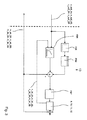
- n_soll_2A to n_soll_3B of the rotational speeds of the electrical machines 9 to 12 is determined for each of the wheels of the vehicle drive train 1, wherein a separate speed controller is provided in the sixth function block FB6 for each wheel Simulation system 14 is a in Fig. 3 used controller structure with a feedforward control and a setpoint feedforward control.
- the measured shaft torques m_actual_2A to m_ist_3B are each added as a disturbance variable to the manipulated variable of the rotational speed controller of the sixth functional block FB6
- the gradient of the speed setpoint values of the electrical machines is formed in function block FB8 and multiplied in function block FB9 by a constant proportional to the moment of inertia of the electrical machine and added to the manipulated variable of the dehumidifier of the six function block FB6.
Landscapes
- Physics & Mathematics (AREA)
- General Physics & Mathematics (AREA)
- Electric Propulsion And Braking For Vehicles (AREA)
- Control Of Driving Devices And Active Controlling Of Vehicle (AREA)
- Testing Of Devices, Machine Parts, Or Other Structures Thereof (AREA)
Applications Claiming Priority (1)
| Application Number | Priority Date | Filing Date | Title |
|---|---|---|---|
| DE200810041883 DE102008041883A1 (de) | 2008-09-09 | 2008-09-09 | Verfahren zum Betreiben eines Prüfstandes für Fahrzeugantriebsstränge |
Publications (2)
| Publication Number | Publication Date |
|---|---|
| EP2161560A2 true EP2161560A2 (fr) | 2010-03-10 |
| EP2161560A3 EP2161560A3 (fr) | 2016-06-08 |
Family
ID=41401769
Family Applications (1)
| Application Number | Title | Priority Date | Filing Date |
|---|---|---|---|
| EP09167059.6A Withdrawn EP2161560A3 (fr) | 2008-09-09 | 2009-08-03 | Procédé de commande d'un banc d'essai de transmissions de puissance de véhicules |
Country Status (2)
| Country | Link |
|---|---|
| EP (1) | EP2161560A3 (fr) |
| DE (1) | DE102008041883A1 (fr) |
Cited By (12)
| Publication number | Priority date | Publication date | Assignee | Title |
|---|---|---|---|---|
| DE102009034555A1 (de) * | 2009-07-23 | 2011-01-27 | Dr. Ing. H.C. F. Porsche Aktiengesellschaft | Prüfstand und Prüfverfahren zur dynamischen Prüfung eines Prüflings mit einem Hybridantrieb |
| WO2011038429A1 (fr) * | 2009-10-02 | 2011-04-07 | Kristl, Seibt & Co. Gesellschaft M.B.H. | Procédé et banc d'essai permettant de reproduire le comportement routier d'un véhicule |
| WO2011151240A1 (fr) * | 2010-05-31 | 2011-12-08 | Avl List Gmbh | Procédé de contrôle de systèmes de chaînes cinématiques |
| WO2012088393A1 (fr) | 2010-12-23 | 2012-06-28 | Horiba Instruments, Inc. | Systèmes et procédés de simulation de patinage |
| WO2015157788A1 (fr) * | 2014-04-16 | 2015-10-22 | Kristl, Seibt & Co. Gesellschaft M.B.H. | Procédé de simulation du comportement d'un véhicule et banc d'essai de véhicule |
| CN106255871A (zh) * | 2014-03-31 | 2016-12-21 | 罗陀泰斯特国际股份公司 | 用于在机动车的测功机测试中使用的方法和系统 |
| WO2018104270A1 (fr) * | 2016-12-05 | 2018-06-14 | Avl List Gmbh | Procédé de commande d'une machine d'application de charge lors d'une marche d'essai d'une chaîne cinématique et banc d'essai |
| WO2018185286A1 (fr) * | 2017-04-07 | 2018-10-11 | Avl List Gmbh | Procédé permettant de commander, en particulier de régler, un banc d'essai de chaîne cinématique comprenant une transmission réelle |
| AT522354A4 (de) * | 2019-08-12 | 2020-10-15 | Avl List Gmbh | Verfahren zum Betreiben eines Prüfstands |
| CN112329316A (zh) * | 2020-11-19 | 2021-02-05 | 中国汽车技术研究中心有限公司 | 一种基于多体动力学的扭力梁强度分析方法 |
| CN113791598A (zh) * | 2021-07-29 | 2021-12-14 | 哈尔滨理工大学 | 极端工况下四轮力矩分配在环测试装置及转矩优化方法 |
| AT524086A1 (de) * | 2020-08-14 | 2022-02-15 | Avl List Gmbh | Prüfstand zum Testen eines realen Prüflings im Fahrbetrieb |
Families Citing this family (2)
| Publication number | Priority date | Publication date | Assignee | Title |
|---|---|---|---|---|
| AT516629B1 (de) | 2014-12-22 | 2016-07-15 | Avl List Gmbh | Verfahren und Vorrichtung zum Durchführen eines Prüflaufs auf einem Prüfstand |
| AT524780B1 (de) | 2021-05-25 | 2022-09-15 | Avl List Gmbh | Verfahren zur Regelung einer Prüfstandsanordnung |
Citations (1)
| Publication number | Priority date | Publication date | Assignee | Title |
|---|---|---|---|---|
| EP1037030A2 (fr) * | 1999-03-12 | 2000-09-20 | Avl Deutschland Gmbh | Procédé de simulation du comportement d'une voiture sur une chaussée |
Family Cites Families (6)
| Publication number | Priority date | Publication date | Assignee | Title |
|---|---|---|---|---|
| DE1105637B (de) * | 1958-09-30 | 1961-04-27 | Siemens Ag | Fahrzeugpruefstand, insbesondere fuer dynamische Untersuchungen an Kraftfahrzeugen |
| DE3801647C2 (de) * | 1988-01-21 | 1995-02-02 | Licentia Gmbh | Verfahren und Vorrichtung zur Prüfung eines Allradaggregats |
| DE3812824A1 (de) * | 1988-04-16 | 1989-11-02 | Asea Brown Boveri | Pruefstand zum testen des antriebsstranges eines fahrzeuges |
| US6634218B1 (en) * | 1999-04-28 | 2003-10-21 | Horiba, Ltd | Engine testing apparatus |
| AT412916B (de) * | 2002-07-19 | 2005-08-25 | Avl List Gmbh | Verfahren zur simulation des fahrverhaltens von fahrzeugen |
| DE10328461A1 (de) * | 2003-06-25 | 2005-01-20 | Daimlerchrysler Ag | Fahrzeugprüfstand |
-
2008
- 2008-09-09 DE DE200810041883 patent/DE102008041883A1/de not_active Withdrawn
-
2009
- 2009-08-03 EP EP09167059.6A patent/EP2161560A3/fr not_active Withdrawn
Patent Citations (1)
| Publication number | Priority date | Publication date | Assignee | Title |
|---|---|---|---|---|
| EP1037030A2 (fr) * | 1999-03-12 | 2000-09-20 | Avl Deutschland Gmbh | Procédé de simulation du comportement d'une voiture sur une chaussée |
Cited By (26)
| Publication number | Priority date | Publication date | Assignee | Title |
|---|---|---|---|---|
| DE102009034555A1 (de) * | 2009-07-23 | 2011-01-27 | Dr. Ing. H.C. F. Porsche Aktiengesellschaft | Prüfstand und Prüfverfahren zur dynamischen Prüfung eines Prüflings mit einem Hybridantrieb |
| DE102009034555B4 (de) * | 2009-07-23 | 2020-08-13 | Dr. Ing. H.C. F. Porsche Aktiengesellschaft | Prüfstand und Prüfverfahren zur dynamischen Prüfung eines Prüflings mit einem Hybridantrieb |
| WO2011038429A1 (fr) * | 2009-10-02 | 2011-04-07 | Kristl, Seibt & Co. Gesellschaft M.B.H. | Procédé et banc d'essai permettant de reproduire le comportement routier d'un véhicule |
| WO2011151240A1 (fr) * | 2010-05-31 | 2011-12-08 | Avl List Gmbh | Procédé de contrôle de systèmes de chaînes cinématiques |
| WO2012088393A1 (fr) | 2010-12-23 | 2012-06-28 | Horiba Instruments, Inc. | Systèmes et procédés de simulation de patinage |
| EP2656275A1 (fr) * | 2010-12-23 | 2013-10-30 | Horiba Instruments, Inc. | Systèmes et procédés de simulation de patinage |
| EP2656275A4 (fr) * | 2010-12-23 | 2014-11-26 | Horiba Instr Inc | Systèmes et procédés de simulation de patinage |
| CN106255871B (zh) * | 2014-03-31 | 2019-07-30 | 罗陀泰斯特国际股份公司 | 用于在机动车的测功机测试中使用的方法和系统 |
| CN106255871A (zh) * | 2014-03-31 | 2016-12-21 | 罗陀泰斯特国际股份公司 | 用于在机动车的测功机测试中使用的方法和系统 |
| EP3126811A4 (fr) * | 2014-03-31 | 2017-12-20 | Rototest International AB | Procédé et système à utiliser dans un essai dynamométrique d'un véhicule à moteur |
| US10444119B2 (en) | 2014-03-31 | 2019-10-15 | Rototest International Ab | Method and system for use in dynamometer testing of a motor vehicle |
| WO2015157788A1 (fr) * | 2014-04-16 | 2015-10-22 | Kristl, Seibt & Co. Gesellschaft M.B.H. | Procédé de simulation du comportement d'un véhicule et banc d'essai de véhicule |
| US9841351B2 (en) | 2014-04-16 | 2017-12-12 | Kristl, Seibt & Co. Gesellschaft M.B.H. | Method for simulating the behavior of the vehicle and chassis dynamometer |
| WO2018104270A1 (fr) * | 2016-12-05 | 2018-06-14 | Avl List Gmbh | Procédé de commande d'une machine d'application de charge lors d'une marche d'essai d'une chaîne cinématique et banc d'essai |
| US10962445B2 (en) | 2016-12-05 | 2021-03-30 | Avl List Gmbh | Method for controlling a load machine during a test run with a drive train and test stand |
| WO2018185286A1 (fr) * | 2017-04-07 | 2018-10-11 | Avl List Gmbh | Procédé permettant de commander, en particulier de régler, un banc d'essai de chaîne cinématique comprenant une transmission réelle |
| US11619565B2 (en) | 2017-04-07 | 2023-04-04 | Avl List Gmbh | Method for controlling, more particularly in a closed-loop manner, a powertrain test bench with real transmission |
| WO2021026578A1 (fr) * | 2019-08-12 | 2021-02-18 | Avl List Gmbh | Procédé d'utilisation d'un banc d'essai |
| AT522354B1 (de) * | 2019-08-12 | 2020-10-15 | Avl List Gmbh | Verfahren zum Betreiben eines Prüfstands |
| AT522354A4 (de) * | 2019-08-12 | 2020-10-15 | Avl List Gmbh | Verfahren zum Betreiben eines Prüfstands |
| US11740158B2 (en) | 2019-08-12 | 2023-08-29 | Avl List Gmbh | Method for operating a test bench in order to determine a torque and a speed |
| AT524086A1 (de) * | 2020-08-14 | 2022-02-15 | Avl List Gmbh | Prüfstand zum Testen eines realen Prüflings im Fahrbetrieb |
| AT524086B1 (de) * | 2020-08-14 | 2022-07-15 | Avl List Gmbh | Prüfstand zum Testen eines realen Prüflings im Fahrbetrieb |
| CN112329316A (zh) * | 2020-11-19 | 2021-02-05 | 中国汽车技术研究中心有限公司 | 一种基于多体动力学的扭力梁强度分析方法 |
| CN113791598A (zh) * | 2021-07-29 | 2021-12-14 | 哈尔滨理工大学 | 极端工况下四轮力矩分配在环测试装置及转矩优化方法 |
| CN113791598B (zh) * | 2021-07-29 | 2024-04-26 | 哈尔滨理工大学 | 极端工况下四轮力矩分配在环测试装置及转矩优化方法 |
Also Published As
| Publication number | Publication date |
|---|---|
| EP2161560A3 (fr) | 2016-06-08 |
| DE102008041883A1 (de) | 2010-03-11 |
Similar Documents
| Publication | Publication Date | Title |
|---|---|---|
| EP2161560A2 (fr) | Procédé de commande d'un banc d'essai de transmissions de puissance de véhicules | |
| EP3548860B1 (fr) | Procédé de contrôle d'un dynamomètre d'absorption pendant une épreuve d'un arbre de transmission et banc d'essai | |
| EP1037030B1 (fr) | Procédé de simulation du comportement d'une voiture sur une chaussée | |
| EP3172550B1 (fr) | Procédé et banc d'essai pour tester un raccordement de composants d'un véhicule | |
| EP3237875B1 (fr) | Procédé et dispositif pour effectuer un cycle d'essai sur un banc d'essai | |
| EP3132243B1 (fr) | Procédé de simulation du comportement d'un véhicule et banc d'essai de véhicule | |
| EP2670644B1 (fr) | Procédé et dispositif pour surveiller le bon fonctionnement d'au moins un premier et un second composant de la chaîne cinématique d'un véhicule | |
| EP3092471B1 (fr) | Procédé et dispositif de régulation d'un banc d'essai de chaîne cinématique | |
| WO2011038429A1 (fr) | Procédé et banc d'essai permettant de reproduire le comportement routier d'un véhicule | |
| AT502946B1 (de) | Verfahren und vorrichtung zur kennfeldermittlung zur steuerung eines schaltprozesses für vollautomatische oder automatisierte getriebe eines kraftfahrzeuges | |
| DE102019132437B4 (de) | Verfahren und Antriebssystem zur Schätzung von Gelenkwellenmomenten in Antriebssträngen | |
| DE3801647C2 (de) | Verfahren und Vorrichtung zur Prüfung eines Allradaggregats | |
| EP3631402B1 (fr) | Banc d'essai de véhicule et procédé de détermination d'une accélération longitudinale de véhicule | |
| AT524086A1 (de) | Prüfstand zum Testen eines realen Prüflings im Fahrbetrieb | |
| DE102019100323A1 (de) | Diagnose eines Verdrehspiels im Antriebsstrang | |
| DE102013019483A1 (de) | Verfahren und Vorrichtung zur Schwingungsdämpfung einer angetriebenen Achse mit Momentenquerverteilung | |
| DE102008020410A1 (de) | Kurven-Spurassistent bei Beschleunigung | |
| DE102011114303A1 (de) | Verfahren zum Verringern einer mechanischen Belastung mindestens einer Komponente des Antriebsstrangs eines Kraftfahrzeugs sowie entsprechendes Kraftfahrzeug | |
| DE102020205690A1 (de) | Verfahren zur Ermittlung Fahrzeuggeschwindigkeit und Fahrerassistenzsystem | |
| DE102011004127B4 (de) | Berechnen eines Drehzahlsignals in einem Kraftfahrzeug | |
| DE102015212240A1 (de) | Aktive Schwingungsdämpfung in einem Antriebsstrang | |
| DE102022206618A1 (de) | Schätzeinrichtung und Verfahren zum Ermitteln von Bewegungsschätzwerten | |
| DE102012009002A1 (de) | Verfahren zum Betreiben eines Prüfstands | |
| DE102021133400A1 (de) | Verfahren und Vorrichtung zur Gradientenbegrenzung eines an einem Drehmomentübertragungselement eines drehschwingungsfähigen Antriebssystems anliegenden Drehmoments | |
| DE102022200305A1 (de) | Verfahren und Vorrichtung zur Ermittlung einer Reifenlängssteifigkeit |
Legal Events
| Date | Code | Title | Description |
|---|---|---|---|
| PUAI | Public reference made under article 153(3) epc to a published international application that has entered the european phase |
Free format text: ORIGINAL CODE: 0009012 |
|
| AK | Designated contracting states |
Kind code of ref document: A2 Designated state(s): AT BE BG CH CY CZ DE DK EE ES FI FR GB GR HR HU IE IS IT LI LT LU LV MC MK MT NL NO PL PT RO SE SI SK SM TR |
|
| AX | Request for extension of the european patent |
Extension state: AL BA RS |
|
| PUAL | Search report despatched |
Free format text: ORIGINAL CODE: 0009013 |
|
| AK | Designated contracting states |
Kind code of ref document: A3 Designated state(s): AT BE BG CH CY CZ DE DK EE ES FI FR GB GR HR HU IE IS IT LI LT LU LV MC MK MT NL NO PL PT RO SE SI SK SM TR |
|
| AX | Request for extension of the european patent |
Extension state: AL BA RS |
|
| RIC1 | Information provided on ipc code assigned before grant |
Ipc: G01M 13/02 20060101AFI20160502BHEP |
|
| 17P | Request for examination filed |
Effective date: 20161107 |
|
| 17Q | First examination report despatched |
Effective date: 20170324 |
|
| STAA | Information on the status of an ep patent application or granted ep patent |
Free format text: STATUS: THE APPLICATION IS DEEMED TO BE WITHDRAWN |
|
| 18D | Application deemed to be withdrawn |
Effective date: 20171005 |