EP2161560A2 - Method for operating a test stand for vehicle power transmissions - Google Patents
Method for operating a test stand for vehicle power transmissions Download PDFInfo
- Publication number
- EP2161560A2 EP2161560A2 EP09167059A EP09167059A EP2161560A2 EP 2161560 A2 EP2161560 A2 EP 2161560A2 EP 09167059 A EP09167059 A EP 09167059A EP 09167059 A EP09167059 A EP 09167059A EP 2161560 A2 EP2161560 A2 EP 2161560A2
- Authority
- EP
- European Patent Office
- Prior art keywords
- vehicle
- wheels
- wheel
- determined
- ist
- Prior art date
- Legal status (The legal status is an assumption and is not a legal conclusion. Google has not performed a legal analysis and makes no representation as to the accuracy of the status listed.)
- Withdrawn
Links
Images

Classifications
-
- G—PHYSICS
- G01—MEASURING; TESTING
- G01M—TESTING STATIC OR DYNAMIC BALANCE OF MACHINES OR STRUCTURES; TESTING OF STRUCTURES OR APPARATUS, NOT OTHERWISE PROVIDED FOR
- G01M13/00—Testing of machine parts
- G01M13/02—Gearings; Transmission mechanisms
- G01M13/025—Test-benches with rotational drive means and loading means; Load or drive simulation
Definitions
- the invention relates to a method for operating a test bench for vehicle drive trains according to the type defined in more detail in the preamble of patent claim 1,
- a test stand for testing a drive train of a vehicle from the internal combustion engine to the drive axles is known.
- Inertia moments, spring stiffnesses and damping dimensions are simulated by means of electronic functional elements or by means of a computer, wherein torque-controlled electrical loading machines serve as transmission elements between the electronic functional elements or the computer and the test stand with the test object. At least two independent loading machines are flanged directly to the shafts of the drive train to be tested.
- the vehicle resistance torque reduced by the wheel torques is fed to a first integrator with a time constant proportional to the vehicle moment of inertia, wherein the angular velocity proportional to the vehicle speed can be tapped off at the first integrator.
- the tire slip occurring in addition to the vehicle longitudinal dynamics is taken into account as a function of the current wheel torques.
- a control or simulation system for simulating the influence of vehicle mass and driving resistance.
- the balance of forces on the vehicle is integrated, wherein the result of this simulation is a target speed of the vehicle or a proportional thereto target speed of the loading machines, which is set via a speed control of the test bench.
- tire slip or wheel slip In real vehicles, there is always a difference between the speed proportional to the vehicle speed and the actual speed of the wheels during the transmission of a force between the drive wheels and a road, which is normally referred to as so-called tire slip or wheel slip.
- the occurring wheel slip is at in the EP 0 338 373 B1 proposed simulation substitutes that is added to the resulting from the vehicle longitudinal dynamics vehicle speed or to the proportional speed dependent on the measured actual torque percentage slip.
- This percentage slip value is determined from characteristics that assign a fixed percentage slip to a measured actual torque, and this procedure is performed separately for each wheel of the drive train.
- the resulting speed setpoint is finally adjusted via the speed control of the test bench.
- the dynamic behavior of the wheels is taken into account via the damping and stiffness parameters of the wheels in the control parameters of the speed controller.
- operating states with quasi-stationary tire slip can be simulated with sufficient accuracy
- operating state characteristics which are characterized by rapid dynamic changes and extreme driving situations, such as suddenly spinning wheels, are simulated by the maximum torque of the loading machines or the manipulated variable of the speed controller is limited to the maximum transmissible torque at given wheel and road parameters.
- the speed control is no longer active or ineffective during this procedure, so during simulation of an operating condition of a vehicle driveline with spinning wheels no corresponding speed setpoint is calculated, or is no longer computable, since this section is not specifiable as a function of the actual torque and therefore also not stored in the system.
- the EP 1 037 030 B1 another system, namely the system of torque control of the loading machine with the calculation of the measured wheel speeds.
- the wheel speed is measured, from which the tire model, using a vehicle speed and a tire tread force, transmits a force transmitted from the tire at that wheel speed to the road and a desired torque for the torque-controlled load machine attached to that shaft determines that between a nominal speed value corresponding to the vehicle speed supplied to the tire model, which is calculated by returning the force transmitted to the roadway in the vehicle model, and the measured wheel speed, a difference corresponding to the real occurring slip.
- the present invention has for its object to provide a method for operating a test bed for vehicle drive trains available by means of which a realistic replica of the dynamic behavior of a drive train of a vehicle with different road surfaces and road profiles, especially the simulation of spinning wheels, with high control stability and low tax and regulatory burden is feasible.
- the desired value of the rotational speed of the electric machine can already be limited during the setpoint calculation to the extent that in the area of the electrical machines no impermissibly high rotational speeds occur during the simulation. This is a simple way to operate a test bench without additional facilities for speed limitation, such as speed control knob or the like, cost and with less control effort.
- the speed setpoint values of the wheels or of the electrical machines can be used as input variables for the tire model by calculating the speed setpoints of the electrical machines via the simulation system.
- the wheels of a vehicle are always fully integrated in the simulation, which in vehicle drive trains with only one drivable vehicle axle, such as rear or front drives, or when operating as Achsgetriebeprüfstand, the unassembled vehicle axles in terms of their speed and lateral dynamic behavior without operation and real co-rotation of the associated machines are considered.
- the method according to the invention for operating a test stand is suitable both for vehicle drive trains which are designed with one, two or even several drivable vehicle axles, such as four-wheel drive vehicles or the like.
- vehicle drive trains which are designed with one, two or even several drivable vehicle axles, such as four-wheel drive vehicles or the like.
- the method according to the invention offers in a simple and cost-effective manner the possibility of realistically simulating the dynamic behavior of a drive train of a vehicle on different road surfaces and in the presence of different roadway profiles and, moreover, taking into account factors which have an influence on the behavior of the drive train during a simulation Due to the feasible in the field of the tire model replica of the tire slip loads occurring in the vehicle drive train, for example, during a spin or a blockage of wheels of a vehicle drive train, such as during driving over ice sheets, realistically simulated.
- the metrologically determined actual torques of the shafts of the drivable vehicle axle are added to the manipulated variable of a speed controller of the speed control during the disturbance variable control, while in the desired value precontrol the gradient of the nominal values of the rotational speeds of the electrical machines with the Inertia moments of the electrical machines are multiplied and added to the manipulated variable of the speed controller in order, in particular during operating state profiles of vehicle drive trains or vehicles that are characterized by high dynamics, the real Vehicle behavior and the performance of the wheels of the drive train to represent as accurately as possible.
- the setpoint values of the rotational speeds of the electric machine are determined in a variant of the method according to the invention by integration of resulting torque values of each wheel, wherein the resulting torque values for each of the wheels of the drivable vehicle axle from a difference between the metrologically determined actual torque of the corresponding shaft and a determined via the tire model, transmitted via a wheel, calculated torque value can be determined.
- a vehicle behavior on the test bench is particularly realistic replicable.
- a simulation of a vehicle behavior which is as realistic as possible is achieved by means of the method according to the invention, in which the speed of the electric machine, which is equivalent to the setpoint speed of the wheel to be imaged by the electric machine, is achieved as a function of the nominal value.
- the respective torque transmitted via a wheel is determined by multiplying the longitudinal and / or transverse forces by a dynamic wheel radius, with which the calculated torque value has a large correspondence with a real transmittable torque value.
- a simulated braking torque which is generated, for example, by friction or by a vehicle brake, a generator-operated electric machine or the like is introduced into the vehicle drive train.
- a constant flowing into the integrative determination of the resulting wheel speed setpoints is determined in a further advantageous variant of the method according to the invention in each case as a function of wheel moments of inertia to be imaged in the region of the electric machine, whereby arbitrary wheel sizes can be simulated on the test bench without conversion of mechanical masses.
- the moment of inertia of the electric machine corresponds at least approximately to the moment of inertia of the wheel of the drivable vehicle axle to be imaged by the electric machine.
- the speed of the vehicle is determined as a function of the determined via the tire model of the longitudinal forces of the wheels of the drivable vehicle axle and in dependence on operating state-dependent driving resistances by integration.
- Dynamic changes in the wheel contact forces of the wheels of the vehicle drive train caused by pitching and rolling of the vehicle are taken into account as a function of predeterminable longitudinal and lateral accelerations of the vehicle and of the terrain in the illustration of the operating behavior of the wheels of the vehicle drive train in a further advantageous variant of the method according to the invention.
- a further variant of the method takes into account for the simulation of cornering real forces acting on the wheels of the vehicle, the be determined by means of the tire model depending on the given slip angle of the wheels.
- lateral forces acting on the wheels of a vehicle are supplied as input variables to a vehicle model setting an operating behavior of the vehicle, a float angle and a yaw rate of the vehicle being determined as a function of a steering angle and various vehicle parameters by means of the vehicle model.
- a vehicle drive train 1 of an all-wheel vehicle which comprises two drivable vehicle axles 2, 3.
- the drivable vehicle axle 2 represents the vehicle front axle
- the drivable vehicle axle 3 represents the vehicle rear axle.
- a torque generated by a drive machine 4 embodied here as an internal combustion engine is transmitted via a transmission device 5 representing a main transmission of the vehicle drive train 1, which may have any conventional transmission design known from practice, and a device arranged between the transmission device 5 and the two vehicle axles 2 and 3 for distributing the torque of the engine 4 between the two drive axles 2 and 3 forwarded.
- the device 6 in the present case is designed as a longitudinal differential and can also have another suitable design for distributing the torque of the drive machine 4 with a fixed distribution factor or a continuously variable distribution factor, depending on the particular application at hand.
- the guided in the vehicle longitudinal direction to the vehicle axles 2 and 3 torque is in the region of a Vorderachsdifferentials 7 and a Schuashsdifferentials 8 in the vehicle transverse direction in equal parts in the direction of a right and in the direction of a left vehicle side on shafts 2A, 2B of the vehicle front axle 2 and Wellen 3A, 3B of the vehicle rear axle 3 forwarded.
- the shafts 2A, 28 of the vehicle front axle 2 and the shafts 3A, 3B of the vehicle rear axle 3 are operatively connected to the vehicle with wheels of the vehicle, whereby the torque provided by the engine 4 in dependence of the translations of the transmission device 5, the device 6, the Vorderachsdifferentials 7 and the rear axle 8 in a correspondingly changed height as the output torque in the range of the waves 2A to 3B is applied.
- the vehicle drive train 1 embodied without wheels here is coupled in each case to electrical machines 9 to 12 whose mass moment of inertia substantially corresponds to the mass moment of inertia of the wheels of the vehicle drive train 1 to be simulated via a test stand 13.
- the electric machines 9 to 12 are both motorized and regenerative in a so-called four-quadrant operation operable, the realistic replica of the dynamic behavior of the vehicle drive train 1 at different road surfaces and road profiles on a in Fig. 2 and Fig. 3 closer illustrated simulation system 14 of the test bed 13 is feasible.
- the electric machines 9 to 12 are coupled through the wheels in the required manner with the shafts 2A to 3B.
- a system with an electric motor drive or a system with a hybrid drive can be used.
- About the simulation system 14 are basically all factors that have an influence on the behavior of the vehicle drive train 1, considered and taken into account.
- the replica of the tire slip the wheels of the vehicle drive train 1 and also the spinning or blocking of the wheels, in particular on ice sheets possible, while occurring loads in the range of the vehicle drive train 1 can be simulated realistically.
- the simulation system 14 of the test rig 13 is in Fig. 2 in the form of a simplified functional diagram shown in more detail.
- the simulation system 14 comprises a so-called vehicle model, which in Fig. 2 graphically represented by a first functional block FB1.
- the vehicle model is supplied with operating parameters characterizing the current operating state of a vehicle, such as a currently traveled road profile, such as a slope or a gradient, a driven road curve, an airspeed and the like.
- operating parameters characterizing the current operating state of a vehicle, such as a currently traveled road profile, such as a slope or a gradient, a driven road curve, an airspeed and the like.
- vehicle model also vehicle parameters, such as a total vehicle weight, geometric dimensions, inertia and suspension parameters for a total vehicle simulation are fed as input variables.
- the vehicle model supplies a vehicle speed v_fzg and tire contact forces F_z, which represent input variables of a tire model of a second function block FB2.
- a behavior of the wheels during the simulation of the behavior of the vehicle drive train 1 is shown, wherein in the region of the tire model, a coefficient of friction of the wheels of the vehicle drive train 1 on the tire slip and additional dynamic changes in the performance of the wheels of the vehicle drive train 1 depending on tire parameters, such a diameter and stiffnesses and elasticities of the tires as well as temperature-dependent tire parameters and the like may be taken into account.
- the tire as well as temperature-dependent tire parameters and the like.
- Both longitudinal forces F_x and transverse forces F_y in the area of the footprint of the wheels of the vehicle drive train 1 are calculated via the tire model and fed to the vehicle model of the first functional block FB1 as input variables.
- the rolling resistance can be determined via the tire model.
- the longitudinal forces F_x of the wheels in a third functional block FB3 of the simulation system 14 are multiplied by the dynamic wheel radius of the wheels of the vehicle drivetrain 1 and actual torques m_act_2A, m_act_2B, m_act_3A and m_jst_3B respectively measured via torque measuring flanges 2A1 and 2B1 or 3A1 and 3B1 Waves 2A to 3B are added, whereby a resulting torque value is determined for each of the wheels,
- braking torques m_B_2A to m_B_3B of the respective wheel are considered by addition in the determination of the resulting torque values.
- the resultant torque values determined for each of the wheels are fed to a fourth function block FB4 as an input quantity and multiplied by a constant, which results in each case from the wheel moments of inertia of the wheels to be simulated, and then fed again to an integrator of a fifth function block FB5 as an input variable.
- the fifth function block FB5 supplies for each of the electric machines 9 to 12 as output value a speed setpoint value n_set_2A to n_set_3B, the speed setpoint values n_set_2A to n_set_3B for both the second function block FB2 as well as for a sixth function block FB6 input values represent.
- n_soll_2A to n_soll_3B of the rotational speeds of the electrical machines 9 to 12 actual values n_actual_2A to n_act_3B of the rotational speeds of the electrical machines 9 to 12 likewise represent input values of the sixth functional block FB6, which Fig. 2 the speed controller of the electric machines 9 to 12 reproduces Grapfisch.
- the sixth function block FB6 outputs, depending on the setpoints n_soll_2A to n_soll_38 of the rotational speeds of the electrical machines 9 to 12, the manipulated variables for current regulators of the electrical machines 9 to 12, the current regulators in Fig. 2 are graphically represented by a seventh functional block FB7.
- setpoint values n_soll_2A to n_soll_3B of the rotational speeds of the electric machines 9 to 12 are calculated for all driving situations, which are set via the speed control in the area of the sixth function block FB6.
- the actual torques m_actual_2A to m_ist_3B of the shafts 2A to 3B of the vehicle front axle 2 and the vehicle rear axle 3 are to be determined metrologically via a dynamic measurement of these torques, wherein the use of current developments of torque measuring flanges with a high cutoff frequency is advantageous for torque measurement.
- a torque transmitted from the measured shaft torque m_actual_2A to m_actual_38 less the torques respectively transmitted via the wheels for each wheel of the vehicle drive train 1 to be considered is transmitted in the tire model of the second functional block FB2
- the corresponding nominal values n_soll_2A to n_soll_3B of the rotational speeds of the wheels are calculated, which are fed back into the tire model as input values.
- braking torques m_B_2A to m_B_3B are also taken into consideration, for example are generated by frictional forces and dissipative forces are therefore not conservative, which can not increase the energies of the wheels. For this reason, the consideration of the braking torque must not lead to an increase in the amount of speed of a wheel. This in turn results from the fact that the wheel or wheels can block at maximum in the presence of a braking torque or a braking force and then has a wheel speed equal to zero. For this reason, the braking force to be taken into account may have to be modified as a function of further boundary conditions in such a way that an increase in the amount of wheel speeds when taking account of a braking torque is avoided.
- the presently used for the integration of torque balances each constant, which corresponds to the reciprocal value of the product of the value 2, the circle number ⁇ and the Radträgheitsmoment, thus determined from the moment of inertia to be simulated.
- the aim is that the moments of inertia of the flanged electric machines 9 to 12 respectively largely correspond to the moments of inertia of the wheels to be simulated.
- both the vehicle model of the first functional block FB1 and the tire models of the criminalsablocks FB2 the pitching and rolling of the vehicle and thus the dynamic changes of the tire contact forces F_z depending on the simulated longitudinal and lateral accelerations of the vehicle and the terrain, for example a slope or a slant is characterized, considered.
- the forces actually occurring in the area of the wheels are taken into account, which can also be determined with the given slip angle via the tire model of the second functional block FB2.
- the lateral forces F_y of each individual wheel are fed to the vehicle model to represent lateral dynamics.
- the vehicle model is used to calculate the slip angle and yaw rate of the vehicle based on the given steering angle and the vehicle parameters, such as mass inertias and vehicle geometries, and thus the distance traveled.
- n_soll_2A to n_soll_3B of the rotational speeds of the electrical machines 9 to 12 is determined for each of the wheels of the vehicle drive train 1, wherein a separate speed controller is provided in the sixth function block FB6 for each wheel Simulation system 14 is a in Fig. 3 used controller structure with a feedforward control and a setpoint feedforward control.
- the measured shaft torques m_actual_2A to m_ist_3B are each added as a disturbance variable to the manipulated variable of the rotational speed controller of the sixth functional block FB6
- the gradient of the speed setpoint values of the electrical machines is formed in function block FB8 and multiplied in function block FB9 by a constant proportional to the moment of inertia of the electrical machine and added to the manipulated variable of the dehumidifier of the six function block FB6.
Abstract
Description
Die Erfindung betrifft ein Verfahren zum Betreiben eines Prüfstandes für Fahrzeugantriebsstränge gemäß der im Oberbegriff des Patentanspruches 1 näher definierten Art,The invention relates to a method for operating a test bench for vehicle drive trains according to the type defined in more detail in the preamble of patent claim 1,
Aus der
Während des Prüfvorganges eines Fahrzeugantriebsstranges wird der zusätzlich zur Fahrzeuglängsdynamik auftretende Reifenschlupf in Abhängigkeit der aktuellen Radmomente berücksichtigt.During the testing process of a vehicle drive train, the tire slip occurring in addition to the vehicle longitudinal dynamics is taken into account as a function of the current wheel torques.
Die statt der Räder an den Antriebswellen des Fahrzeugantriebsstranges angebrachten Belastungsmaschinen sind über einen sogenannten Vier-Quadranten-Betrieb betreibbar, womit von den Belastungsmaschinen ausgehend sowohl ein Antriebsmoment als auch ein Bremsmoment in den Antriebsstrang einleitbar ist.The instead of the wheels on the drive shafts of the vehicle drive train mounted loading machines are operated by a so-called four-quadrant operation, which starting from the loading machines both a drive torque and a braking torque in the drive train can be introduced.
Ein Regelungs- bzw. Simulationssystem ist zum Simulieren des Einflusses der Fahrzeugmasse und der Fahrwiderstände vorgesehen. Die Kräftebilanz am Fahrzeug wird aufintegriert, wobei das Ergebnis dieser Simulation eine Soll-Geschwindigkeit des Fahrzeuges bzw. eine hierzu proportionale Soll-Drehzahl der Belastungsmaschinen ist, die über eine Drehzahlregelung des Prüfstandes eingestellt wird.A control or simulation system is provided for simulating the influence of vehicle mass and driving resistance. The balance of forces on the vehicle is integrated, wherein the result of this simulation is a target speed of the vehicle or a proportional thereto target speed of the loading machines, which is set via a speed control of the test bench.
Bei realen Fahrzeugen liegt während der Übertragung einer Kraft zwischen den Antriebsrädern und einer Fahrbahn immer eine Differenz zwischen der zu der Fahrzeuggeschwindigkeit proportionalen Drehzahl und der tatsächlichen Drehzahl der Räder vor, die normiert als sogenannter Reifenschlupf bzw. Radschlupf bezeichnet wird. Der auftretende Radschlupf wird bei der in der
Der sich daraus ergebende Drehzahl-Sollwert wird schließlich über die Drehzahlregelung des Prüfstandes eingestellt. Das dynamische Verhalten der Räder wird über die Dämpfungs- und Steifigkeitsparameter der Räder in den Regelparametern des Drehzahlreglers berücksichtigt.The resulting speed setpoint is finally adjusted via the speed control of the test bench. The dynamic behavior of the wheels is taken into account via the damping and stiffness parameters of the wheels in the control parameters of the speed controller.
Mit der vorbeschriebenen Vorgehensweise sind Betriebszustände mit quasi stationärem Reifenschlupf ausreichend genau simulierbar, Betriebszustandsverläufe, welche durch schnelle dynamische Änderungen und extreme Fahrsituationen, wie plötzlich durchdrehende Räder, gekennzeichnet sind, werden dadurch simuliert, dass das maximale Drehmoment der Belastungsmaschinen bzw. die Stellgröße des Drehzahlreglers auf das maximal übertragbare Moment bei gegebenen Rad- und Straßenparametern begrenzt wird. Die Drehzahlregelung ist während dieser Vorgehensweise nicht mehr aktiv bzw ohne Wirkung, weshalb während der Simulation eines Betriebszustandeseines Fahrzeugantriebsstranges mit durchdrehenden Rädern kein entsprechender Drehzahlsollwert berechnet wird, bzw. nicht mehr berechenbar ist, da dieser Abschnitt nicht als Funktion des Ist-Drehmomentes angebbar ist und daher im System auch nicht hinterlegt ist.With the above-described procedure, operating states with quasi-stationary tire slip can be simulated with sufficient accuracy, operating state characteristics, which are characterized by rapid dynamic changes and extreme driving situations, such as suddenly spinning wheels, are simulated by the maximum torque of the loading machines or the manipulated variable of the speed controller is limited to the maximum transmissible torque at given wheel and road parameters. The speed control is no longer active or ineffective during this procedure, so during simulation of an operating condition of a vehicle driveline with spinning wheels no corresponding speed setpoint is calculated, or is no longer computable, since this section is not specifiable as a function of the actual torque and therefore also not stored in the system.
Nachteilig dabei ist jedoch, dass während der letztbeschriebenen Simulation von Betriebszuständen eines Fahrzeugantriebsstranges, wie mit durchdrehenden Rändern, auftretende Reibwertänderungen im Bereich zwischen den Rädern und einer Fahrbahn nicht mehr berücksichtigt werden können. Darüber hinaus ist von Nachteil, dass sich die Beschleunigung des Radabtriebes aus der Massenträgheit der elektrischen Maschine ergibt und daher andere Radträgheitsmomente beispielsweise während der Simulation von Betriebszuständen mit durchdrehenden Rädern am Prüfstand nicht abbildbar sind.The disadvantage here is that during the last-described simulation of operating conditions of a vehicle drive train, such as with spinning edges, occurring Reibwertänderungen in the area between the wheels and a roadway can not be considered. In addition, it is disadvantageous that the acceleration of the Radabtriebes from the inertia of the electric machine results and therefore other Radenträgheitsmomente example, during the simulation of operating conditions with spinning wheels on the test stand are not reproducible.
Da der betriebsmäßige Drehzahlregler während der Simulation von durchdrehenden Rädern abgeschaltet ist bzw. nicht im gewünschten Umfang betreibbar ist, besteht die Möglichkeit, dass sich während der Simulation am Prüfstand unzulässig hohe Drehzahhwerte im Bereich der Belastungsmaschinen einstellen. Um derartige Betriebszustände der elektrischen Maschine zu vermeiden, besteht beispielsweise die Möglichkeit, sogenannte Drehzahlfangregler vorzusehen, mittels welchen ebenfalls eine Begrenzung des Drehmomentes der Belastungsmaschine durchführbar ist, um die Drehzahlen der Belastungsmaschinen im zulässigen Bereich zu halten. Derartige Maßnahmen erfordern jedoch nachteilhafterweise zusätzlichen Steuer- und Regelungsaufwand.Since the operational speed controller is switched off during the simulation of spinning wheels or can not be operated to the desired extent, there is the possibility that set during the simulation on the test bench inadmissible high rotational speeds in the field of loading machines. In order to avoid such operating states of the electric machine, for example, it is possible to provide so-called speed-catching controls, by means of which a limitation of the torque of the loading machine can also be carried out in order to keep the speeds of the loading machines within the permissible range. However, such measures disadvantageously require additional control and regulatory effort.
Um diesen Nachteil zu umgehen, verfolgt die
Dieses Verfahren zum Simulieren des Verhaltens eines Fahrzeuges auf einer Fahrbahn an einem Antriebsstrang-Prüfttand mit Hilfe von an den Wellen des Antriebsstranges des Fahrzeuges anbringbaren momentengeregelten, elektrischen Belastungsmaschinen und einem Rechner mit einem darin gespeicherten Fahrzeugmodell und einem die schlupfabhängige Reibung nachbildenden Reifenmodell ist in der
Der vorliegenden Erfindung liegt die Aufgabe zugrunde, ein Verfahren zum Betreiben eines Prüfstandes für Fahrzeugantriebsstränge zur Verfügung zu stellen, mittels welchem eine realitätsnahe Nachbildung des dynamischen Verhaltens eines Antriebsstranges eines Fahrzeuges bei unterschiedlichen Fahrbahnbelägen und Fahrbahnprofilen, insbesondere auch die Simulation von durchdrehenden Rädern, mit hoher Regelungsstabilität und geringem Steuer- und Regelaufwand durchführbar ist.The present invention has for its object to provide a method for operating a test bed for vehicle drive trains available by means of which a realistic replica of the dynamic behavior of a drive train of a vehicle with different road surfaces and road profiles, especially the simulation of spinning wheels, with high control stability and low tax and regulatory burden is feasible.
Erfindungsgemäß wird diese Aufgabe mit einem Verfahren mit den Merkmalen des Patentanspruches 1 gelöst.According to the invention this object is achieved by a method having the features of claim 1.
Aufbauend auf der in der
Weiterhin besteht die Möglichkeit, dass während der Bestimmung der Sollwerte der Drehzahlen der elektrischen Maschinen eine Störgrößenaufschaltung und eine Soilwertvorsteuerung durchgeführt werden.Furthermore, there is the possibility that during the determination of the setpoint values of the rotational speeds of the electrical machines, a feedforward control and a feedforward control are performed.
Mittels des erfindungsgemäßen Verfahrens ist das Verhalten von Fahrzeugantriebssträngen über deren gesamten Betriebsbereich, d. h. sowohl Betriebszustände mit quasistationärem Reifenschlupf und auch durch schnelle dynamische Änderungen und extreme Fahrsituationen gekennzeichnete Betriebszustandsverläufe, mittels einer Drehzahlregelung abbildbar, da die Drehzahlregelung durch die Störgrößenaufschaltung und auch die Sollwertvorsteuerung mit der dafür erforderlichen Dynamik durchführbar ist.By means of the method according to the invention is the behavior of vehicle powertrains over their entire operating range, ie both operating conditions with quasistationärem tire slip and also characterized by fast dynamic changes and extreme driving situations operating state curves, by means of a speed control, as the speed control by the disturbance variable and also the setpoint feedforward with the necessary dynamics is feasible.
Somit besteht auf einfache Art und Weise im Vergleich zu der aus der
Der Sollwert der Drehzahl der elektrischen Maschine ist bereits während der Sollwertberechnung dahingehend begrenzbar, dass sich im Bereich der elektrischen Maschinen keine unzulässig hohen Drehzahlen während der Simukation einstellen. Damit besteht auf einfache Art und Weise die Möglichkeit, einen Prüfstand ohne zusätzliche Einrichtungen zur Drehzahlbegrenzung, wie Drehzahlfangregler oder dergleichen, kostengünstig und mit geringern Steuer- und Regelaufwand zu betreiben.The desired value of the rotational speed of the electric machine can already be limited during the setpoint calculation to the extent that in the area of the electrical machines no impermissibly high rotational speeds occur during the simulation. This is a simple way to operate a test bench without additional facilities for speed limitation, such as speed control knob or the like, cost and with less control effort.
Im Vergleich zu der aus der
Darüber hinaus ist das tatsächliche Trägheitsmoment der Räder für Simulationen bzw, Untersuchungen, für die das exakte Nachbilden des Schwingungsverhaltens nicht entscheidend ist, im Gegensatz zu der aus der
Kleine Unterschiede zwischen den Trägheitsmomenten der zu simulierenden Räder und den Trägheitsmomenten der elektrischen Maschinen, mittels welchen das Betriebsverhalten der Räder darzustellen ist, sind während der Simulation nachbild- und berücksichtigbar, womit das Verhalten des Fahrzeugantriebsstranges im Wesentlichen unabhängig von der Massenträgheit des Prüfstandes bzw. des Prüfaufbaus ist.Small differences between the moments of inertia of the wheels to be simulated and the moments of inertia of the electric machines, by means of which the operating behavior of the wheels is to be simulated and taken into account during the simulation, whereby the behavior of the vehicle driveline substantially independent of the inertia of the test stand or Test setup is.
Zusätzlich sind bei dem erfindungsgemäßen Verfahren die Drehzahl-Sollwerte der Räder bzw. der elektrischen Maschinen durch die Berechnung der Drehzahl-Sollwerte der elektrischen Maschinen über das Simulationssystem als Eingangsgrößen für das Reifenmodell verwendbar. Dies resultiert aus der Tatsache, berechneten betriebszustandsabhängige Drehzahl-Sollwerte stabiler als messtechnisch ermittelte Drehzahlgrößen sind, die mit Ungenauig~ keiten behaftet sein können, und somit im Vergleich zu aus dem Stand der Technik bekannten Verfahren mit der erfindungsgemäßen Vorgehensweise ein stabileres Prüfstandverhalten erreicht wird.In addition, in the method according to the invention, the speed setpoint values of the wheels or of the electrical machines can be used as input variables for the tire model by calculating the speed setpoints of the electrical machines via the simulation system. This results from the fact that calculated operating state-dependent rotational speed target values are more stable than metrologically determined rotational speed variables, which may be subject to inaccuracies, and thus a more stable test bench behavior is achieved in comparison with methods known from the prior art with the procedure according to the invention.
Des Weiteren sind die Räder eines Fahrzeugs immer vollständig in der Simulation integriert, womit bei Fahrzeugantriebssträngen mit nur einer antreibbaren Fahrzeugachse, wie Heck- oder Frontantrieben, bzw. bei einem Betrieb als Achsgetriebeprüfstand, die nicht aufgebauten Fahrzeugachsen hinsichtlich ihrer Drehzahl und des querdynamischen Verhaltens ohne Betrieb und reales Mitdrehen der zugehörigen Maschinen berücksichtigbar sind.Furthermore, the wheels of a vehicle are always fully integrated in the simulation, which in vehicle drive trains with only one drivable vehicle axle, such as rear or front drives, or when operating as Achsgetriebeprüfstand, the unassembled vehicle axles in terms of their speed and lateral dynamic behavior without operation and real co-rotation of the associated machines are considered.
Das erfindungsgemäße Verfahren zum Betreiben eines Prüfstandes ist sowohl für Fahrzeugantriebsstränge geeignet, die mit einer, zwei oder auch mehreren antreibbaren Fahrzeugachsen, wie Allradfahrzeuge oder dergleichen, ausgeführt sind. D. h., dass das Betriebsverhalten von Antriebssträngen mit einer oder auch mehreren antreibbaren Fahrzeugachsen mittels des Verfahrens nach der Erfindung über einen breiten Betriebsbereich am Prüfstand darsteltbar ist.The method according to the invention for operating a test stand is suitable both for vehicle drive trains which are designed with one, two or even several drivable vehicle axles, such as four-wheel drive vehicles or the like. This means that the operating behavior of drive trains with one or more drivable vehicle axles by means of the method according to the invention over a wide operating range on the test stand is darsteltbar.
Das erfindungsgemäße Verfahren bietet auf einfache und kostengünstige Art und Weise die Möglichkeit, das dynamische Verhalten eines Antriebsstranges eines Fahrzeuges auf unterschiedlichen Fahrbahnbelägen und bei Vorliegen verschiedenster Fahrbahnprofile realitätsnah nachzubilden und darüber hinaus während einer Simulation Faktoren, die Einfluss auf das Verhalten des Antriebsstranges haben, zu berücksichtigen, Durch die im Bereich des Reifenmodells durchführbare Nachbildung des Reifenschlupfes sind beispielsweise während einem Durchdrehen bzw. einem Blockieren von Rädern eines Fahrzeugantriebsstranges, beispielsweise während einem Überfahren von Eisplatten, auftretende Belastungen im Fahrzeugantriebsstrang realitätsnah nachbildbar.The method according to the invention offers in a simple and cost-effective manner the possibility of realistically simulating the dynamic behavior of a drive train of a vehicle on different road surfaces and in the presence of different roadway profiles and, moreover, taking into account factors which have an influence on the behavior of the drive train during a simulation Due to the feasible in the field of the tire model replica of the tire slip loads occurring in the vehicle drive train, for example, during a spin or a blockage of wheels of a vehicle drive train, such as during driving over ice sheets, realistically simulated.
Es besteht die Möglichkeit, beim erfindungsgemäßen Verfahren Ist-Drehmomente der Wellen der antreibbaren Fahrzeugachse messtechnisch zu ermitteln und zur Bestimmung der Sollwerte der Drehzahlen der elektrischen Maschine heranzuziehen.In the method according to the invention, it is possible to metrologically determine actual torques of the shafts of the drivable vehicle axle and to use them to determine the nominal values of the rotational speeds of the electric machine.
Bei einer wiederum weiteren vorteilhaften Variante des Verfahrens nach der Erfindung werden bei der Störgrößenaufschaltung die messtechnisch ermittelten Ist-Drehmomente der Wellen der antreibbaren Fahrzeugachse zur Stellgröße eines Drehzahlreglers der Drehzahlregelung addiert, während bei der Sollwertvorsteuerung jeweils der Gradient der Sollwerte der Drehzahlen der elektrischen Maschinen mit den Trägheitsmomenten der elektrischen Maschinen multipliziert und zur Stellgröße des Drehzahlreglers addiert werden, um besonders während Betriebszustandsverläufen von Fahrzeugantriebssträngen bzw. Fahrzeugen, die durch eine hohe Dynamik gekennzeichnet sind, das reale Fahrzeugverhalten bzw. das Betriebsverhalten der Räder des Antriebsstranges möglichst exakt darstellen zu können.In yet another advantageous variant of the method according to the invention, the metrologically determined actual torques of the shafts of the drivable vehicle axle are added to the manipulated variable of a speed controller of the speed control during the disturbance variable control, while in the desired value precontrol the gradient of the nominal values of the rotational speeds of the electrical machines with the Inertia moments of the electrical machines are multiplied and added to the manipulated variable of the speed controller in order, in particular during operating state profiles of vehicle drive trains or vehicles that are characterized by high dynamics, the real Vehicle behavior and the performance of the wheels of the drive train to represent as accurately as possible.
Die Sollwerte der Drehzahlen der elektrischen Maschine werden bei einer Variante des erfindungsgemäßen Verfahrens durch Integration resultierender Drehmomentwerte eines jeden Rades bestimmt, wobei die resultierenden Drehmomentwerte für jedes der Räder der antreibbaren Fahrzeugachse aus einer Differenz aus dem messtechnisch ermittelten Ist-Drehmoment der damit korrespondierenden Welle und einem über das Reifenmodell ermittelten, über ein Rad übertragenen, berechneten Drehmomentwert bestimmt werden. Damit ist ein Fahrzeugverhalten am Prüfstand besonders realistisch nachbildbar.The setpoint values of the rotational speeds of the electric machine are determined in a variant of the method according to the invention by integration of resulting torque values of each wheel, wherein the resulting torque values for each of the wheels of the drivable vehicle axle from a difference between the metrologically determined actual torque of the corresponding shaft and a determined via the tire model, transmitted via a wheel, calculated torque value can be determined. Thus, a vehicle behavior on the test bench is particularly realistic replicable.
Eine möglichst realitätsnahe Nachbildung eines Fahrzeugverhaltens wird mittels des Verfahrens nach der Erfindung, bei welchem in Abhängigkeit des Sollwertes der Drehzahl der elektrischen Maschine, welche zu der Soll-Drehzahl des durch die elektrische Maschine abzubildenden Rades äquivalent ist, erreicht.A simulation of a vehicle behavior which is as realistic as possible is achieved by means of the method according to the invention, in which the speed of the electric machine, which is equivalent to the setpoint speed of the wheel to be imaged by the electric machine, is achieved as a function of the nominal value.
Es besteht die Möglichkeit, in Abhängigkeit der aktuellen Werte der Radschlupfe jeweils die zwischen einem Rad der antreibbaren Fahrzeugachse und einer Fahrbahn übertragenen Längs- und/oder Querkräfte über das Reifenmodell zu bestimmen.Depending on the current wheel slippage values, it is possible in each case to determine the longitudinal and / or transverse forces transmitted between a wheel of the drivable vehicle axle and a roadway via the tire model.
Das jeweils über ein Rad übertragene Drehmoment wird durch Multiplikation der Längs- und/oder Querkräfte mit einem dynamischen Radradius ermittelt, womit der berechnete Drehmomentwert eine große Übereinstimmung mit einem realen übertragbaren Drehmomentwert aufweist.The respective torque transmitted via a wheel is determined by multiplying the longitudinal and / or transverse forces by a dynamic wheel radius, with which the calculated torque value has a large correspondence with a real transmittable torque value.
Bei der Ermittlung der resultierenden Drehmomentwerte besteht die Möglichkeit, jeweils ein simuliertes Bremsmoment zu berücksichtigen, welches beispielsweise durch Reibung erzeugt wird oder von einer Fahrzeugbremse, einer generatorisch betriebenen elektrischen Maschine oder dergleichen in den Fahrzeugantriebsstrang eingeleitet wird.When determining the resulting torque values, it is possible to take into account in each case a simulated braking torque which is generated, for example, by friction or by a vehicle brake, a generator-operated electric machine or the like is introduced into the vehicle drive train.
Eine in die integrative Bestimmung der resultierenden Raddrehzahl-Sollwerte einfließende Konstante wird bei einer weiteren vorteilhaften Variante des Verfahrens nach der Erfindung jeweils in Abhängigkeit von im Bereich der elektrischen Maschine abzubildenden Radträgheitsmomenten bestimmt, womit am Prüfstand ohne Umbau von mechanischen Massen beliebige Radgrößen simulierbar sind.A constant flowing into the integrative determination of the resulting wheel speed setpoints is determined in a further advantageous variant of the method according to the invention in each case as a function of wheel moments of inertia to be imaged in the region of the electric machine, whereby arbitrary wheel sizes can be simulated on the test bench without conversion of mechanical masses.
Um das Schwingungsverhalten eines Fahrzeugantriebsstranges optimal nachbilden zu können, entspricht das Trägheitsmoment der elektrischen Maschine wenigstens annähernd dem Trägheitsmoment des durch die elektrische Maschine abzubildenden Rades der antreibbaren Fahrzeugachse.In order to optimally simulate the vibration behavior of a vehicle drive train, the moment of inertia of the electric machine corresponds at least approximately to the moment of inertia of the wheel of the drivable vehicle axle to be imaged by the electric machine.
Bei einer weiteren vorteilhaften Variante des Verfahrens nach der Erfindung wird die Geschwindigkeit des Fahrzeuges in Abhängigkeit der über das Reifenmodell ermittelten Längskräfte der Räder der antreibbaren Fahrzeugachse und in Abhängigkeit von betriebszustandsabhängigen Fahrwiderständen durch Integration bestimmt.In a further advantageous variant of the method according to the invention, the speed of the vehicle is determined as a function of the determined via the tire model of the longitudinal forces of the wheels of the drivable vehicle axle and in dependence on operating state-dependent driving resistances by integration.
Durch Nicken und Wanken des Fahrzeuges verursachte dynamische Änderungen der Radaufstandskräfte der Räder des Fahrzeugantriebsstranges werden in Abhängigkeit von vorgebbaren Längs- und Querbeschleunigungen des Fahrzeuges sowie der Geländebeschaffenheit bei der Abbildung des Betriebsverhaltens der Räder des Fahrzeugantriebsstranges bei einer weiteren vorteilhaften Variante des Verfahrens nach der Erfindung berücksichtigt.Dynamic changes in the wheel contact forces of the wheels of the vehicle drive train caused by pitching and rolling of the vehicle are taken into account as a function of predeterminable longitudinal and lateral accelerations of the vehicle and of the terrain in the illustration of the operating behavior of the wheels of the vehicle drive train in a further advantageous variant of the method according to the invention.
Eine weitere Variante des Verfahrens berücksichtigt zur Simulation von Kurvenfahrten real an den Rädern des Fahrzeuges angreifende Kräfte, die mittels des Reifenmodells in Abhängigkeit gegebener Schräglaufwinkel der Räder ermittelt werden.A further variant of the method takes into account for the simulation of cornering real forces acting on the wheels of the vehicle, the be determined by means of the tire model depending on the given slip angle of the wheels.
Während einer Kurvenfahrt jeweils an den Rädern eines Fahrzeuges angreifende Querkräfte werden bei einer weiteren Variante des Verfahrens einem ein Betriebsverhalten des Fahrzeuges abbindenden Fahrzeugmodell als Eingangsgrößen zugeführt, wobei mittels des Fahrzeugmodells ein Schwimmwinkel und eine Gierrate des Fahrzeuges in Abhängigkeit eines Lenkwinkels und verschiedener Fahrzeugparameter bestimmt werden. Damit ist ein reales Verhalten eines Fahrzeuges möglichst umfassend theoretisch abbildbar.In a further variant of the method, during a cornering lateral forces acting on the wheels of a vehicle are supplied as input variables to a vehicle model setting an operating behavior of the vehicle, a float angle and a yaw rate of the vehicle being determined as a function of a steering angle and various vehicle parameters by means of the vehicle model. This is a real behavior of a vehicle as comprehensively theoretically possible.
Weitere Vorteile und vorteilhafte Weiterbildungen der Erfindung ergeben sich aus den Patentansprüchen und dem unter Bezugnahme auf die Zeichnung prinzipmäßig beschriebenen Ausführungsbeispiel.Further advantages and advantageous developments of the invention will become apparent from the claims and the embodiment described in principle with reference to the drawings.
- Fig. 1Fig. 1
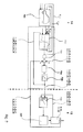
- eine stark schematisierte Darstellung eines Fahrzeugantriebsstranges und eines Prüfstandes für Fahrzeugantriebsstränge;a highly schematic representation of a vehicle drive train and a test bench for vehicle drive trains;
- Fig. 2Fig. 2
-
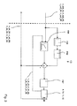
eine vereinfachte Funktionsdarstellung einer Simulationsstruktur des Prüfstandes gemäß
Fig. 1 ; unda simplified functional representation of a simulation structure of the test bench according toFig. 1 ; and - Fig. 3Fig. 3
-
eine Funktionsdarstellung einer Drehzahlregelung des Prüfstandes gemäß
Fig. 1 .a functional representation of a speed control of the test in accordance withFig. 1 ,
In
Ein von einer vorliegend als Verbrennungsmotor ausgebildeten Antriebmaschine 4 erzeugtes Drehmoment wird über eine vorliegend ein Hauptgetriebe des Fahrzeugantriebsstranges 1 darstellende Getriebeeinrichtung 5, die jede beliebige aus der Praxis bekannte Getriebebauform aufweisen kann, und einem zwischen der Getriebeeinrichtung 5 und den beiden Fahrzeugachsen 2 und 3 angeordneten Einrichtung zum Verteilen des Drehmomentes der Antriebsmaschine 4 zwischen den beiden Antriebsachsen 2 und 3 weitergeleitet. Dabei ist die Einrichtung 6 vorliegend als Längsdifferential ausgebildet und kann in Abhängigkeit des jeweils vorliegenden Anwendungsfalles auch eine andere geeignete Bauart zum Verteilen des Drehmoments der Antriebsmaschine 4 mit festem Verteilungsfaktor oder stufenlos variierbarem Verteilungsfaktor aufweisen,A torque generated by a drive machine 4 embodied here as an internal combustion engine is transmitted via a transmission device 5 representing a main transmission of the vehicle drive train 1, which may have any conventional transmission design known from practice, and a device arranged between the transmission device 5 and the two vehicle axles 2 and 3 for distributing the torque of the engine 4 between the two drive axles 2 and 3 forwarded. In this case, the device 6 in the present case is designed as a longitudinal differential and can also have another suitable design for distributing the torque of the drive machine 4 with a fixed distribution factor or a continuously variable distribution factor, depending on the particular application at hand.
Es besteht auch die Möglichkeit, statt dem Verbrennungsmotor einen Elektromotor oder eine Kombination aus Elektromotor und Verbrennungsmotor zu verwenden.It is also possible, instead of the internal combustion engine to use an electric motor or a combination of electric motor and internal combustion engine.
Das in Fahrzeuglängsrichtung zu den Fahrzeugachsen 2 und 3 geführte Drehmoment wird im Bereich eines Vorderachsdifferentials 7 und eines Hinterashsdifferentials 8 in Fahrzeugquerrichtung jeweils zu gleichen Teilen in Richtung einer rechten und in Richtung einer linken Fahrzeugseite auf Wellen 2A, 2B der Fahrzeugvorderachse 2 bzw. Wellen 3A, 3B der Fahrzeughinterachse 3 weitergeleitet.The guided in the vehicle longitudinal direction to the vehicle axles 2 and 3 torque is in the region of a Vorderachsdifferentials 7 and a Hinterashsdifferentials 8 in the vehicle transverse direction in equal parts in the direction of a right and in the direction of a left vehicle side on
Die Wellen 2A, 28 der Fahrzeugvorderachse 2 und die Wellen 3A, 3B der Fahrzeughinterachse 3 sind beim realen Fahrzeug mit Rädern des Fahrzeuges wirkverbunden, womit das von der Antriebsmaschine 4 zur Verfügung gestellte Drehmoment in Abhängigkeit der Übersetzungen der Getriebeeinrichtung 5, der Einrichtung 6, des Vorderachsdifferentials 7 und des Hinterachsdifferentials 8 in entsprechend gewandelter Höhe als Abtriebsmoment im Bereich der Wellen 2A bis 3B anliegt.The
Der vorliegend ohne Räder ausgeführte Fahrzeugantriebsstrang 1 ist im Bereich der Wellen 2A bis 3B jeweils mit elektrischen Maschinen 9 bis 12 gekoppelt, deren Massenträgheitsmoment vorliegend im Wesentlichen dem Massenträgheitsmoment der über einen Prüfstand 13 zu simulierenden Räder des Fahrzeugantriebsstranges 1 entsprechen. Die elektrischen Maschinen 9 bis 12 sind sowohl motorisch als auch generatorisch in einem sogenannten Vier-Quadranten-Betrieb betreibbar, wobei die realitätsnahe Nachbildung des dynamischen Verhaltens des Fahrzeugantriebsstranges 1 bei unterschiedlichen Fahrbahnbelägen und Fahrbahnprofilen über ein in
Abweichend hiervon besteht jedoch auch die Möglichkeit, am Prüfstand 13 ein Betriebsverhalten eines gesamten Fahrzeugzeugaufbaus zu testen und zu simulieren, wobei dies mit Fahrzeugen mit und auch ohne Räder durchführbar ist. Für den Fall, dass ein Fahrzeug oder ein Fahrzeugantriebsstrang mit Rädern betrachtet wird, werden die elektrischen Maschinen 9 bis 12 durch die Räder hindurch in der erforderlichen Art und Weise mit den Wellen 2A bis 3B gekoppelt.Deviating from this, however, it is also possible to test and simulate a performance of an entire vehicle body structure on the
Neben einem Fahrzeug mit Verbrennungsmotor kann auch ein System mit einem Elektromotor als Antrieb oder ein System mit einem Hybridantrieb verwendet werden.In addition to a vehicle with an internal combustion engine, a system with an electric motor drive or a system with a hybrid drive can be used.
Es besteht auch die Möglichkeit, das Hinterachsdifferenzial 8 und die elektrischen Maschinen 11 und 12 durch eine einzige elektrische Maschine zu ersetzen, welche direkt mit der Kardanwelle 15 oder dem Getriebeabtrieb zusammenwirkt.It is also possible to replace the rear differential 8 and the
Über das Simulationssystem 14 sind grundsätzlich alle Faktoren, die Einfluss auf das Verhalten des Fahrzeugantriebsstranges 1 haben, betracht- und berücksichtigbar. Somit ist beispielsweise die Nachbildung des Reifenschlupfes der Räder des Fahrzeugantriebsstranges 1 und auch das Durchdrehen bzw. Blockieren der Räder insbesondere auf Eisplatten möglich, wobei dabei auftretende Belastungen im Bereich des Fahrzeugantriebsstranges 1 realitätsnah nachgebildet werden können.About the
Das Simulationssystem 14 des Prüfstandes 13 ist in
Im Bereich des ersten Funktionsblockes FB1 wird das Fahrzeugmodell mit den aktuellen Betriebszustand eines Fahrzeuges charakterisierenden Betriebsparametern wie beispielsweise einem aktuell befahrenen Straßenprofil, wie einer Steigung oder einem Gefälle, einer durchfahrenen Fahrbahnkurve, einer Luftgeschwindigkeit und dergleichen, als Eingangsgrößen versorgt. Darüber hinaus werden dem Fahrzeugmodell auch Fahrzeugparameter, wie beispielsweise ein Fahrzeuggesamtgewicht, geometrische Abmessungen, Massenträgheiten und Fahrwerkparameter für eine Gesamtfahrzeugsimulation als Einganggrößen zugeführt.In the area of the first functional block FB1, the vehicle model is supplied with operating parameters characterizing the current operating state of a vehicle, such as a currently traveled road profile, such as a slope or a gradient, a driven road curve, an airspeed and the like. In addition, the vehicle model also vehicle parameters, such as a total vehicle weight, geometric dimensions, inertia and suspension parameters for a total vehicle simulation are fed as input variables.
Als Ausgangsgrößen liefert das Fahrzeugmodell eine Fahrzeuggeschwindigkeit v_fzg sowie Reifenaufstandskräfte F_z, weiche Eingangsgrößen eines Reifensmodells eines zweiten Funktionsblockes FB2 darstellen. Über das Reifenmodell wird ein Betriebsverhalten der Räder während der Simulation des Verhaltens des Fahrzeugantriebsstranges 1 abgebildet, wobei im Bereich des Reifenmodells ein Reibwertverlauf der Räder des Fahrzeugantriebsstranges 1 über dem Reifenschlupf und zusätzliche dynamische Änderungen des Betriebsverhaltens der Räder des Fahrzeugantriebsstranges 1 in Abhängigkeit von Reifenparametern, wie ein Durchmesser und Steifigkeiten und Elastizitäten der Reifen sowie temperaturabhängige Reifenparameter und dergleichen, berücksichtigt werden. der Reifen sowie temperaturabhängige Reifenparameter und dergleichen, berücksichtigt werden.As output variables, the vehicle model supplies a vehicle speed v_fzg and tire contact forces F_z, which represent input variables of a tire model of a second function block FB2. Over the tire model, a behavior of the wheels during the simulation of the behavior of the vehicle drive train 1 is shown, wherein in the region of the tire model, a coefficient of friction of the wheels of the vehicle drive train 1 on the tire slip and additional dynamic changes in the performance of the wheels of the vehicle drive train 1 depending on tire parameters, such a diameter and stiffnesses and elasticities of the tires as well as temperature-dependent tire parameters and the like may be taken into account. the tire as well as temperature-dependent tire parameters and the like.
Über das Reifenmodell werden sowohl Längskräfte F_x und Querkräfte F_y im Bereich der Aufstandsfläche der Räder des Fahrzeugantriebsstranges 1 berechnet und dem Fahrzeugmodell des ersten Funktionsblockes FB1 als Eingangsgrößen zugeführt.Both longitudinal forces F_x and transverse forces F_y in the area of the footprint of the wheels of the vehicle drive train 1 are calculated via the tire model and fed to the vehicle model of the first functional block FB1 as input variables.
Es besteht auch die Möglichkeit, ein Rückstelldrehmoment über das Reifenmodell zu berechnen und für das Fahrzeugmodell zu verwenden. Zusätzlich kann über das Reifenmodell der Rollwiderstand bestimmt werden. Gleichzeitig werden die Längskräfte F_x der Räder in einem dritten Funktionsblock FB3 des Simulationssystems 14 mit dem dynamischen Radradius der Räder des Fahrzeugantriebsstranges 1 multipliziert und jeweils zu über Drehmomentmessflansche 2A1 und 2B1 bzw. 3A1 und 3B1 gemessenen Ist-Drehmomenten m_ist_2A, m_ist_2B, m_ist_3A und m_jst_3B der Wellen 2A bis 3B addiert, womit für jedes der Räder ein resultierender Drehmomentwert bestimmt wird,It is also possible to calculate a restoring torque on the tire model and to use for the vehicle model. In addition, the rolling resistance can be determined via the tire model. At the same time, the longitudinal forces F_x of the wheels in a third functional block FB3 of the
In Abhängigkeit des jeweils zu betrachtenden Betriebszustandes des mit dem Fahrzeugantriebsstrang 1 ausgebildeten Fahrzeuges werden bei der Ermittlung der resultierenden Drehmomentwerte Bremsmomente m_B_2A bis m_B_3B des jeweiligen Rades durch Addition berücksichtigt. Anschließend werden die für jedes der Räder ermittelten resultierenden Drehmomentwerte einem vierten Funktionsblock FB4 als Eingangsgröße zugeführt und mit einer Konstanten, welche sich jeweils aus den zu simulierenden Radträgheitsmomenten der Räder ergibt, multipliziert und anschließend einem Integrierer eines fünften Funktionsblockes FB5 wiederum als Eingangsgröße zugeführt. Der fünfte Funktionsblock FB5 liefert für jede der elektrischen Maschinen 9 bis 12 als Ausgangswert einen Drehzahl-Sollwert n_soll_2A bis n_soll_3B, wobei die Drehzahl-Sollwerte n_soll_2A bis n_soll_3B sowohl für den zweiten Funktionsblock FB2 als auch für einen sechsten Funktionsblock FB6 Eingangswerte darstellen.Depending on the respective operating state of the vehicle drive train 1 to be considered, braking torques m_B_2A to m_B_3B of the respective wheel are considered by addition in the determination of the resulting torque values. Subsequently, the resultant torque values determined for each of the wheels are fed to a fourth function block FB4 as an input quantity and multiplied by a constant, which results in each case from the wheel moments of inertia of the wheels to be simulated, and then fed again to an integrator of a fifth function block FB5 as an input variable. The fifth function block FB5 supplies for each of the electric machines 9 to 12 as output value a speed setpoint value n_set_2A to n_set_3B, the speed setpoint values n_set_2A to n_set_3B for both the second function block FB2 as well as for a sixth function block FB6 input values represent.
Neben den Sollwerten n_soll_2A bis n_soll_3B der Drehzahlen der elektrischen Maschinen 9 bis 12 stellen Ist-Werte n_ist_2A bis n_ist_3B der Drehzahlen der elektrischen Maschinen 9 bis 12 ebenfalls Eingangswerte des sechsten Funktionsblockes FB6 dar, der in
Über das Simulationssystem 14 des Prüfstandes 13 werden nur die nicht real vorhandenen Systeme des Fahrzeugantriebsstranges, wie die Räder, Bremsen, die Fahrzeugmassen, die Umgebungsbedingungen des Fahrzeuges, die Straßenbeschaffenheit und das Straßenprofil sowie ein Verhalten des Fahrers simuliert. Zur Simulation der Räder bzw. der Reifen sind aus der Praxis bekannte Reifenmodelle einsetzbar, mittels welchen ein exakter Reibwertverlauf über dem Reifenschlupf und zusätzlich die dynamischen Änderungen anhand von Reifensteifigkeiten und -dämpfungen in Längs-, Quer- und Vertikalrichtung berücksichtigbar sind.About the
Bei durchdrehenden Rädern wird die Bestimmung der Sollwerte der Drehzahlen der elektrischen Maschinen 9 bis 12 beibehalten und die Drehzahlregelung nicht verlassen, womit eine zusätzliche Begrenzung des Drehzahlreglers im Bereich des sechsten Funktionsblockes FB6 auf ein im Bereich der Räder jeweils maximal übertragbares Drehmoment nicht erforderlich ist. Somit werden für alle Fahrsituationen Sollwerte n_soll_2A bis n_soll_3B der Drehzahlen der elektrischen Maschinen 9 bis 12 berechnet, die über die Drehzahlregelung im Bereich des sechsten Funktionsblockes FB6 eingestellt werden.With spinning wheels, the determination of the setpoint values of the rotational speeds of the electrical machines 9 to 12 is maintained and the speed control is not left, so that an additional limitation of the speed controller in the area of the sixth function block FB6 is not required on a maximum torque transmissible in the region of the wheels. Thus, setpoint values n_soll_2A to n_soll_3B of the rotational speeds of the electric machines 9 to 12 are calculated for all driving situations, which are set via the speed control in the area of the sixth function block FB6.
Grundsätzlich sind die Ist-Drehmomente m_ist_2A bis m_ist_3B der Wellen 2A bis 3B der Fahrzeugvorderachse 2 und der Fahrzeughinterachse 3 messtechnisch über eine dynamische Messung dieser Drehmomente zu ermitteln, wobei zur Drehmomentmessung der Einsatz von aktuellen Entwicklungen von Drehmomentmessflanschen mit hoher Grenzfrequenz vorteilhaft ist.In principle, the actual torques m_actual_2A to m_ist_3B of the
Während der Bestimmung der Sollwerte n_soll_2A bis n_soll_3B der Drehzahlen der elektrischen Maschinen 9 bis 12 wird für jedes zu betrachtende Rad des Fahrzeugantriebsstranges 1 ein aus dem gemessenen Wellenmoment m_ist_2A bis m_ist_38 abzüglich der jeweils über die Räder übertragenen Drehmomente, die im Reifenmodell des zweiten Funktionsblockes FB2 durch Multiplikation der Längskräfte F_x mit dem dynamischen Radradius der Räder berechnet wird, die Drehmomentbilanz erstellt, Durch Integration der resultierenden Drehmomente im Funktionsblock FB5 werden die entsprechenden Sollwerte n_soll_2A bis n_soll_3B der Drehzahlen der Räder berechnet, die dem Reifenmodell wieder als Eingangswerte zugeführt werden.During the determination of the setpoint values n_soll_2A to n_soll_3B of the rotational speeds of the electric machines 9 to 12, a torque transmitted from the measured shaft torque m_actual_2A to m_actual_38 less the torques respectively transmitted via the wheels for each wheel of the vehicle drive train 1 to be considered is transmitted in the tire model of the second functional block FB2 By integrating the resulting torques in function block FB5, the corresponding nominal values n_soll_2A to n_soll_3B of the rotational speeds of the wheels are calculated, which are fed back into the tire model as input values.
Über das Reifenmodell werden aus den Sollwerten der Drehzahlen der elektrischen Maschinen 9 bis 12, die zu den Sollwerten der Drehzahlen der Räder äquivalent sind, und der entsprechenden Fahrzeuggeschwindigkeit v_fzg für jedes Rad ein aktueller Reifenschlupf und damit die aktuell zwischen der Fahrbahn und den Rädern jeweils übertragenen Kräfte in Längs- und in Querrichtung berechnet, wobei sowohl die Längskräfte F_x und die Querkräfte F_y Funtkionen der Reifen und Fahrbahnparameter, der Reifenaufstandskräfte F_z und des Reifenschlupfes sind. Das mit den Längskräften F_x korrespondierende und über die Räder übertragene Drehmoment ergibt sich jeweils durch Multiplikation der Längskräfte F_x mit den dynamischen Radradien,From the setpoint values of the rotational speeds of the electric machines 9 to 12, which are equivalent to the target values of the rotational speeds of the wheels, and the corresponding vehicle speed v_fzg for each wheel, a current tire slip and thus the distance between the roadway and the wheels are transmitted via the tire model Forces are calculated in the longitudinal and in the transverse direction, wherein both the longitudinal forces F_x and the transverse forces F_y are functions of the tires and road parameters, the tire contact forces F_z and the tire slip. The torque corresponding to the longitudinal forces F_x and transmitted via the wheels results in each case by multiplying the longitudinal forces F_x by the dynamic wheel radii,
Bei der Erstellung der Drehmomentbilanzen im Bereich der Räder werden auch Bremsmomente m_B_2A bis m_B_3B berücksichtigt, die beispielsweise durch Reibungskräfte erzeugt werden und dissipative also nicht konservative Kräfte sind, die die Energien der Räder nicht erhöhen können. Aus diesem Grund darf die Berücksichtigung der Bremsmomente nicht zu einer Erhöhung des Betrages der Drehzahl eines Rades führen. Die resultiert wiederum aus der Tatsache, dass das oder die Räder bei Vorliegen eines Bremsmomentes bzw. einer Bremskraft maximal blockieren können und dann eine Raddrehzahl gleich null aufweist. Aus diesem Grund ist die zu berücksichtigende Bremskraft gegebenenfalls in Abhängigkeit weiterer Randbedingungen dahingehend zu modifizieren, dass ein Anstieg des Betrages der Raddrehzahlen bei einer Berücksichtigung eines Bremsmomentes vermieden wird.When the torque balances are generated in the area of the wheels, braking torques m_B_2A to m_B_3B are also taken into consideration, for example are generated by frictional forces and dissipative forces are therefore not conservative, which can not increase the energies of the wheels. For this reason, the consideration of the braking torque must not lead to an increase in the amount of speed of a wheel. This in turn results from the fact that the wheel or wheels can block at maximum in the presence of a braking torque or a braking force and then has a wheel speed equal to zero. For this reason, the braking force to be taken into account may have to be modified as a function of further boundary conditions in such a way that an increase in the amount of wheel speeds when taking account of a braking torque is avoided.
Die vorliegend zur Integration der Drehmomentbilanzen jeweils verwendete Konstante, welche dem reziproken Wert des Produktes aus dem Wert 2, der Kreiszahl Π und dem Radträgheitsmoment entspricht, bestimmt sich somit aus dem zu simulierenden Radträgheitsmoment. In Abhängigkeit des jeweils vorliegenden Anwendungsfalles können hierfür auch andere Trägheitsmomente als das der aufgebauten elektrischen Maschinen 9 bis 12 eingesetzt werden, womit am Prüfstand ohne Umbau von mechanischen Massen auch andere Radgrößen simulierbar sind, Um das Schwingungsverhalten des Systems optimal nachbilden zu können, wird angestrebt, dass die Trägheitsmomente der angeflanschten elektrischen Maschinen 9 bis 12 jeweils den Trägheitsmomenten der zu simulierenden Räder weitestgehend entsprechen.The presently used for the integration of torque balances each constant, which corresponds to the reciprocal value of the product of the value 2, the circle number Π and the Radträgheitsmoment, thus determined from the moment of inertia to be simulated. Depending on the particular application case, other moments of inertia than that of the built-up electrical machines 9 to 12 can be used, which also other wheel sizes can be simulated on the test bed without modification of mechanical masses. In order to optimally simulate the vibration behavior of the system, the aim is that the moments of inertia of the flanged electric machines 9 to 12 respectively largely correspond to the moments of inertia of the wheels to be simulated.
Zusätzlich sind sowohl über das Fahrzeugmodell des ersten Funktionsblockes FB1 als auch über die Reifenmodelle des Funktionablockes FB2 das Nicken und Wanken des Fahrzeuges und damit die dynamischen Änderungen der Reifenaufstandskräfte F_z in Abhängigkeit von den simulierten Längs- und Querbeschleunigungen des Fahrzeugs sowie der Geländebeschaffenheit, die beispielsweise durch eine Steigung oder eine Schrägfahrt charakterisiert ist, berücksichtigbar.In addition, both the vehicle model of the first functional block FB1 and the tire models of the Funktionsablocks FB2 the pitching and rolling of the vehicle and thus the dynamic changes of the tire contact forces F_z depending on the simulated longitudinal and lateral accelerations of the vehicle and the terrain, for example a slope or a slant is characterized, considered.
Zur Simulation von Kurvenfahrten des Fahrzeuges werden die real im Bereich der Räder auftretenden Kräfte, speziell die für die Spurhaltung verantwortlichen Quer- oder Seitenkräfte F_y, berücksichtigt, die mit dem gegebenen Schräglaufwinkel ebenfalls über das Reifenmodell des zweiten Funktionsblockes FB2 ermittelbar sind. Die Querkräfte F_yjedes einzelnen Rades werden dem Fahrzeugmodell zur Darstellung einer Querdynamik zugeführt. Über das Fahrzeugmodell wird anhand des vorgegebenen Lenkwinkels und der Fahrzeugparameter, wie Massenträgheiten und Fahrzeuggeometrien, der Schwimmwinkel und die Gierrate des Fahrzeuges und damit die zurückgelegte Kurve berechnet.To simulate cornering of the vehicle, the forces actually occurring in the area of the wheels, especially the transverse or lateral forces F_y responsible for tracking, are taken into account, which can also be determined with the given slip angle via the tire model of the second functional block FB2. The lateral forces F_y of each individual wheel are fed to the vehicle model to represent lateral dynamics. The vehicle model is used to calculate the slip angle and yaw rate of the vehicle based on the given steering angle and the vehicle parameters, such as mass inertias and vehicle geometries, and thus the distance traveled.
Über das Simulationssystem 14 des Prüfstandes 13 wird für jedes der Räder des Fahrzeugantriebsstranges 1 ein separater Sollwert n_soll_2A bis n_soll_3B der Drehzahlen der elektrischen Maschinen 9 bis 12 ermittelt, wobei für jedes Rad ein separater Drehzahlregler im sechsten Funktionsblock FB6 vorgesehen ist Zur Verbesserung des dynamischen Verhaltens des Simulationssystems 14 wird eine in
Bei der Sollwert-Vorsteuerung wird im Funktionsblock FB8 der Gradient der Drehzahl-Sollwerte der elektrischen Maschinen gebildet und im Funktionsblock FB9 mit einer dem Trägheitsmoment der elektrischen Maschine proportionalen Konstante multipliziert und zur Stellgröße des Dehzahlreglers des sechsen Funktionsblockes FB6 addiert.In the setpoint feedforward control, the gradient of the speed setpoint values of the electrical machines is formed in function block FB8 and multiplied in function block FB9 by a constant proportional to the moment of inertia of the electrical machine and added to the manipulated variable of the dehumidifier of the six function block FB6.
Zusätzlich werden über die Sollwert-Vorsteuerung schnelle Änderungen der Führungsgröße ermöglicht, wobei jeweils der Gradient der Sollwerte n_soll_2A bis n_soll_3B der Drehzahlen der elektrischen Maschinen 9 bis 12 mit dem eigenen Massenträgheitsmoment der aufgebauten elektrischen Maschinen 9 bis 12 multipliziert wird. Sowohl über die Störgrößenaufschaltung als auch über die Sollwert-Vorsteuerung ist die Drehzahlregelung der elektrischen Maschinen 9 bis 12 bei dynamischen Betriebszustandsverläufen des Fahrzeugantriebsstranges 1 mit hoher Dynamik der elektrischen Maschinen 9 bis 12 durchführbar.In addition, rapid changes in the reference variable are made possible via the setpoint feedforward control, with the gradient of the setpoint values n_soll_2A to n_soll_3B of the rotational speeds of the electric machines 9 to 12, respectively is multiplied by the own moment of inertia of the constructed electric machines 9 to 12. The speed control of the electrical machines 9 to 12 can be carried out with dynamic dynamics of the electric machines 9 to 12 both via the feedforward control and via the setpoint feedforward control during dynamic operating state profiles of the vehicle drive train 1.
- 11
- FahrzeugantriebsstrangVehicle powertrain
- 22
- Fahrzeugachsevehicle axle
- 2A, 2B2A, 2B
- Wellewave
- 2A1, 2B12A1, 2B1
- Drehmomentmessflanschtorque flange
- 33
- Fahrzeugachsevehicle axle
- 3A, 383A, 38
- Wellewave
- 3A1, 3B13A1, 3B1
- Drehmomentmessflanschtorque flange
- 44
- Antriebsmaschineprime mover
- 55
- Getriebeeinrichtungtransmission device
- 66
- Einrichtung zum Verteilen von DrehmomentenDevice for distributing torques
- 77
- Vorderachsdifferentialfront axle
- 88th
- Hinterachsdifferentialrear differential
- 9 bis 129 to 12
- elektrische Maschinenelectrical machines
- 1313
- Prüfstandtest bench
- 1414
- Simulationssystemsimulation system
- 1515
- Kardanwellepropeller shaft
- FB1 bis FB7FB1 to FB7
- Funktionsblockfunction block
- F_xf_x
- Längskraftlongitudinal force
- F_yF_y
- Querkraftlateral force
- F_zF_Z
- ReifenaufstandskraftTire contact force
- m_ist_2A bis m_is_3Bm_ist_2A to m_is_3B
- Wellendrehmomentshaft torque
- m_B_2A bis m_B_3Bm_B_2A to m_B_3B
- Bremsmomentebraking torques
- n_soll_2A bis n_soll_3Bn_soll_2A to n_soll_3B
- Sollwerte der Drehzahl der elektrischen MaschinenSetpoint values of the rotational speed of the electrical machines
- n_ist_2A bis n_ist_3Bn_ist_2A to n_ist_3B
- Ist-Drehzahlen der elektrischen MaschinenActual speeds of electrical machines
- V_fzgv_fzg
- Fahrzeuggeschwindigkeitvehicle speed
Claims (15)
Applications Claiming Priority (1)
| Application Number | Priority Date | Filing Date | Title |
|---|---|---|---|
| DE200810041883 DE102008041883A1 (en) | 2008-09-09 | 2008-09-09 | Method for operating a test bench for vehicle drive trains |
Publications (2)
| Publication Number | Publication Date |
|---|---|
| EP2161560A2 true EP2161560A2 (en) | 2010-03-10 |
| EP2161560A3 EP2161560A3 (en) | 2016-06-08 |
Family
ID=41401769
Family Applications (1)
| Application Number | Title | Priority Date | Filing Date |
|---|---|---|---|
| EP09167059.6A Withdrawn EP2161560A3 (en) | 2008-09-09 | 2009-08-03 | Method for operating a test stand for vehicle power transmissions |
Country Status (2)
| Country | Link |
|---|---|
| EP (1) | EP2161560A3 (en) |
| DE (1) | DE102008041883A1 (en) |
Cited By (13)
| Publication number | Priority date | Publication date | Assignee | Title |
|---|---|---|---|---|
| DE102009034555A1 (en) * | 2009-07-23 | 2011-01-27 | Dr. Ing. H.C. F. Porsche Aktiengesellschaft | Test stand e.g. drive chain test stand, for testing test sample of hybrid drive in e.g. internal combustion engine of motor vehicle, has simulating device serving as voltage reducing unit that is provided in generator region of machine |
| WO2011038429A1 (en) * | 2009-10-02 | 2011-04-07 | Kristl, Seibt & Co. Gesellschaft M.B.H. | Method and test stand for simulating the driving behavior of a vehicle |
| WO2011151240A1 (en) * | 2010-05-31 | 2011-12-08 | Avl List Gmbh | Method for verifying drive train systems |
| WO2012088393A1 (en) | 2010-12-23 | 2012-06-28 | Horiba Instruments, Inc. | Wheel slip simulation systems and methods |
| WO2015157788A1 (en) * | 2014-04-16 | 2015-10-22 | Kristl, Seibt & Co. Gesellschaft M.B.H. | Method for simulating the behaviour of the vehicle and chassis dynamometer |
| CN106255871A (en) * | 2014-03-31 | 2016-12-21 | 罗陀泰斯特国际股份公司 | The method and system used in testing at the dynamometer machine of motor vehicles |
| WO2018104270A1 (en) * | 2016-12-05 | 2018-06-14 | Avl List Gmbh | Method for controlling a load machine during a test run with a drive train and test stand |
| WO2018185286A1 (en) * | 2017-04-07 | 2018-10-11 | Avl List Gmbh | Method for controlling, more particularly in a closed-loop manner, a powertrain test bench with real transmission |
| AT522354B1 (en) * | 2019-08-12 | 2020-10-15 | Avl List Gmbh | Procedure for operating a test bench |
| CN112329316A (en) * | 2020-11-19 | 2021-02-05 | 中国汽车技术研究中心有限公司 | Torsion beam strength analysis method based on multi-body dynamics |
| CN113791598A (en) * | 2021-07-29 | 2021-12-14 | 哈尔滨理工大学 | Four-wheel moment distribution in-loop testing device under extreme working condition and torque optimization method |
| AT524086A1 (en) * | 2020-08-14 | 2022-02-15 | Avl List Gmbh | Test stand for testing a real test specimen in driving operation |
| CN113791598B (en) * | 2021-07-29 | 2024-04-26 | 哈尔滨理工大学 | Four-wheel moment distribution ring testing device under extreme working condition and torque optimizing method |
Families Citing this family (2)
| Publication number | Priority date | Publication date | Assignee | Title |
|---|---|---|---|---|
| AT516629B1 (en) * | 2014-12-22 | 2016-07-15 | Avl List Gmbh | Method and device for carrying out a test run on a test bench |
| AT524780B1 (en) | 2021-05-25 | 2022-09-15 | Avl List Gmbh | Procedure for controlling a test bench arrangement |
Citations (1)
| Publication number | Priority date | Publication date | Assignee | Title |
|---|---|---|---|---|
| EP1037030A2 (en) * | 1999-03-12 | 2000-09-20 | Avl Deutschland Gmbh | Procedure for simulating the behaviour of a vehicle on a roadway |
Family Cites Families (6)
| Publication number | Priority date | Publication date | Assignee | Title |
|---|---|---|---|---|
| DE1105637B (en) * | 1958-09-30 | 1961-04-27 | Siemens Ag | Vehicle test bench, especially for dynamic tests on motor vehicles |
| DE3801647C2 (en) * | 1988-01-21 | 1995-02-02 | Licentia Gmbh | Method and device for testing a four-wheel drive unit |
| DE3812824A1 (en) * | 1988-04-16 | 1989-11-02 | Asea Brown Boveri | TEST TEST FOR TESTING THE DRIVELINE OF A VEHICLE |
| US6634218B1 (en) * | 1999-04-28 | 2003-10-21 | Horiba, Ltd | Engine testing apparatus |
| AT412916B (en) * | 2002-07-19 | 2005-08-25 | Avl List Gmbh | PROCESS FOR SIMULATING THE DRIVING BEHAVIOR OF VEHICLES |
| DE10328461A1 (en) * | 2003-06-25 | 2005-01-20 | Daimlerchrysler Ag | Chassis dynamometer |
-
2008
- 2008-09-09 DE DE200810041883 patent/DE102008041883A1/en not_active Withdrawn
-
2009
- 2009-08-03 EP EP09167059.6A patent/EP2161560A3/en not_active Withdrawn
Patent Citations (1)
| Publication number | Priority date | Publication date | Assignee | Title |
|---|---|---|---|---|
| EP1037030A2 (en) * | 1999-03-12 | 2000-09-20 | Avl Deutschland Gmbh | Procedure for simulating the behaviour of a vehicle on a roadway |
Cited By (26)
| Publication number | Priority date | Publication date | Assignee | Title |
|---|---|---|---|---|
| DE102009034555A1 (en) * | 2009-07-23 | 2011-01-27 | Dr. Ing. H.C. F. Porsche Aktiengesellschaft | Test stand e.g. drive chain test stand, for testing test sample of hybrid drive in e.g. internal combustion engine of motor vehicle, has simulating device serving as voltage reducing unit that is provided in generator region of machine |
| DE102009034555B4 (en) * | 2009-07-23 | 2020-08-13 | Dr. Ing. H.C. F. Porsche Aktiengesellschaft | Test bench and test procedure for dynamic testing of a test object with a hybrid drive |
| WO2011038429A1 (en) * | 2009-10-02 | 2011-04-07 | Kristl, Seibt & Co. Gesellschaft M.B.H. | Method and test stand for simulating the driving behavior of a vehicle |
| WO2011151240A1 (en) * | 2010-05-31 | 2011-12-08 | Avl List Gmbh | Method for verifying drive train systems |
| WO2012088393A1 (en) | 2010-12-23 | 2012-06-28 | Horiba Instruments, Inc. | Wheel slip simulation systems and methods |
| EP2656275A1 (en) * | 2010-12-23 | 2013-10-30 | Horiba Instruments, Inc. | Wheel slip simulation systems and methods |
| EP2656275A4 (en) * | 2010-12-23 | 2014-11-26 | Horiba Instr Inc | Wheel slip simulation systems and methods |
| CN106255871B (en) * | 2014-03-31 | 2019-07-30 | 罗陀泰斯特国际股份公司 | For method and system used in the dynamometer machine test in motor vehicle |
| CN106255871A (en) * | 2014-03-31 | 2016-12-21 | 罗陀泰斯特国际股份公司 | The method and system used in testing at the dynamometer machine of motor vehicles |
| EP3126811A4 (en) * | 2014-03-31 | 2017-12-20 | Rototest International AB | Method and system for use in dynamometer testing of a motor vehicle |
| US10444119B2 (en) | 2014-03-31 | 2019-10-15 | Rototest International Ab | Method and system for use in dynamometer testing of a motor vehicle |
| WO2015157788A1 (en) * | 2014-04-16 | 2015-10-22 | Kristl, Seibt & Co. Gesellschaft M.B.H. | Method for simulating the behaviour of the vehicle and chassis dynamometer |
| US9841351B2 (en) | 2014-04-16 | 2017-12-12 | Kristl, Seibt & Co. Gesellschaft M.B.H. | Method for simulating the behavior of the vehicle and chassis dynamometer |
| WO2018104270A1 (en) * | 2016-12-05 | 2018-06-14 | Avl List Gmbh | Method for controlling a load machine during a test run with a drive train and test stand |
| US10962445B2 (en) | 2016-12-05 | 2021-03-30 | Avl List Gmbh | Method for controlling a load machine during a test run with a drive train and test stand |
| WO2018185286A1 (en) * | 2017-04-07 | 2018-10-11 | Avl List Gmbh | Method for controlling, more particularly in a closed-loop manner, a powertrain test bench with real transmission |
| US11619565B2 (en) | 2017-04-07 | 2023-04-04 | Avl List Gmbh | Method for controlling, more particularly in a closed-loop manner, a powertrain test bench with real transmission |
| WO2021026578A1 (en) * | 2019-08-12 | 2021-02-18 | Avl List Gmbh | Method for operating a test bench |
| AT522354A4 (en) * | 2019-08-12 | 2020-10-15 | Avl List Gmbh | Procedure for operating a test bench |
| AT522354B1 (en) * | 2019-08-12 | 2020-10-15 | Avl List Gmbh | Procedure for operating a test bench |
| US11740158B2 (en) | 2019-08-12 | 2023-08-29 | Avl List Gmbh | Method for operating a test bench in order to determine a torque and a speed |
| AT524086A1 (en) * | 2020-08-14 | 2022-02-15 | Avl List Gmbh | Test stand for testing a real test specimen in driving operation |
| AT524086B1 (en) * | 2020-08-14 | 2022-07-15 | Avl List Gmbh | Test stand for testing a real test specimen in driving operation |
| CN112329316A (en) * | 2020-11-19 | 2021-02-05 | 中国汽车技术研究中心有限公司 | Torsion beam strength analysis method based on multi-body dynamics |
| CN113791598A (en) * | 2021-07-29 | 2021-12-14 | 哈尔滨理工大学 | Four-wheel moment distribution in-loop testing device under extreme working condition and torque optimization method |
| CN113791598B (en) * | 2021-07-29 | 2024-04-26 | 哈尔滨理工大学 | Four-wheel moment distribution ring testing device under extreme working condition and torque optimizing method |
Also Published As
| Publication number | Publication date |
|---|---|
| EP2161560A3 (en) | 2016-06-08 |
| DE102008041883A1 (en) | 2010-03-11 |
Similar Documents
| Publication | Publication Date | Title |
|---|---|---|
| EP2161560A2 (en) | Method for operating a test stand for vehicle power transmissions | |
| EP3548860B1 (en) | Method for controlling an absorbing dynamometer during a power train test and test bench | |
| EP1037030B1 (en) | Procedure for simulating the behaviour of a vehicle on a roadway | |
| EP3172550B1 (en) | Method and test rig for testing a combination of components of a vehicle | |
| EP3237875B1 (en) | Method and device for performing a test run on a test stand | |
| DE102010030599B4 (en) | Acceleration control device for vehicles | |
| EP3132243B1 (en) | Method for simulating the behaviour of the vehicle and chassis dynamometer | |
| EP2670644B1 (en) | Method and device for monitoring the proper functioning of at least one first and a second component of a vehicle drive train | |
| DE10336542A1 (en) | Performance determination for hybrid vehicles | |
| WO2011038429A1 (en) | Method and test stand for simulating the driving behavior of a vehicle | |
| DE102011085103B4 (en) | Method for regulating the driving dynamics of a motor vehicle | |
| AT502946B1 (en) | METHOD AND DEVICE FOR FIELD DETECTION FOR CONTROLLING A SWITCHING PROCESS FOR FULLY AUTOMATED OR AUTOMATED TRANSMISSIONS OF A MOTOR VEHICLE | |
| EP3092471B1 (en) | Method and device for controlling a powertrain test stand | |
| DE3801647C2 (en) | Method and device for testing a four-wheel drive unit | |
| AT524086A1 (en) | Test stand for testing a real test specimen in driving operation | |
| DE102019100323A1 (en) | Diagnosis of a backlash in the drive train | |
| DE102013019483A1 (en) | Method and device for vibration damping of a driven axle with moment transverse distribution | |
| DE102019132437B4 (en) | Method and drive system for estimating propeller shaft torques in drive trains | |
| DE102008020410A1 (en) | Purpose braking method for driving wheel of motor vehicle output shaft, involves obtaining braking torque in closed control loop, and outputting obtained braking torque to multiple braking devices | |
| EP3631402B1 (en) | Vehicle test stand and method for ascertaining a vehicle longitudinal acceleration | |
| DE102011114303A1 (en) | Method for reducing a mechanical load on at least one component of the drive train of a motor vehicle and corresponding motor vehicle | |
| DE102011004127B4 (en) | Calculating a speed signal in a motor vehicle | |
| DE102015212240A1 (en) | Active vibration damping in a drive train | |
| DE102022206618A1 (en) | Estimation device and method for determining movement estimates | |
| DE102021133400A1 (en) | Method and device for limiting the gradient of a torque applied to a torque transmission element of a drive system capable of torsional vibration |
Legal Events
| Date | Code | Title | Description |
|---|---|---|---|
| PUAI | Public reference made under article 153(3) epc to a published international application that has entered the european phase |
Free format text: ORIGINAL CODE: 0009012 |
|
| AK | Designated contracting states |
Kind code of ref document: A2 Designated state(s): AT BE BG CH CY CZ DE DK EE ES FI FR GB GR HR HU IE IS IT LI LT LU LV MC MK MT NL NO PL PT RO SE SI SK SM TR |
|
| AX | Request for extension of the european patent |
Extension state: AL BA RS |
|
| PUAL | Search report despatched |
Free format text: ORIGINAL CODE: 0009013 |
|
| AK | Designated contracting states |
Kind code of ref document: A3 Designated state(s): AT BE BG CH CY CZ DE DK EE ES FI FR GB GR HR HU IE IS IT LI LT LU LV MC MK MT NL NO PL PT RO SE SI SK SM TR |
|
| AX | Request for extension of the european patent |
Extension state: AL BA RS |
|
| RIC1 | Information provided on ipc code assigned before grant |
Ipc: G01M 13/02 20060101AFI20160502BHEP |
|
| 17P | Request for examination filed |
Effective date: 20161107 |
|
| 17Q | First examination report despatched |
Effective date: 20170324 |
|
| STAA | Information on the status of an ep patent application or granted ep patent |
Free format text: STATUS: THE APPLICATION IS DEEMED TO BE WITHDRAWN |
|
| 18D | Application deemed to be withdrawn |
Effective date: 20171005 |