EP2161232A2 - Package brake and automatic winder including the same - Google Patents
Package brake and automatic winder including the same Download PDFInfo
- Publication number
- EP2161232A2 EP2161232A2 EP09168228A EP09168228A EP2161232A2 EP 2161232 A2 EP2161232 A2 EP 2161232A2 EP 09168228 A EP09168228 A EP 09168228A EP 09168228 A EP09168228 A EP 09168228A EP 2161232 A2 EP2161232 A2 EP 2161232A2
- Authority
- EP
- European Patent Office
- Prior art keywords
- take
- tube
- holding member
- force
- package
- Prior art date
- Legal status (The legal status is an assumption and is not a legal conclusion. Google has not performed a legal analysis and makes no representation as to the accuracy of the status listed.)
- Withdrawn
Links
- 230000009471 action Effects 0.000 claims abstract description 85
- 239000012530 fluid Substances 0.000 claims description 51
- 238000004804 winding Methods 0.000 claims description 47
- 239000002783 friction material Substances 0.000 claims description 24
- 238000010586 diagram Methods 0.000 description 10
- 230000007547 defect Effects 0.000 description 7
- 238000000034 method Methods 0.000 description 5
- 230000008569 process Effects 0.000 description 5
- CVOFKRWYWCSDMA-UHFFFAOYSA-N 2-chloro-n-(2,6-diethylphenyl)-n-(methoxymethyl)acetamide;2,6-dinitro-n,n-dipropyl-4-(trifluoromethyl)aniline Chemical compound CCC1=CC=CC(CC)=C1N(COC)C(=O)CCl.CCCN(CCC)C1=C([N+]([O-])=O)C=C(C(F)(F)F)C=C1[N+]([O-])=O CVOFKRWYWCSDMA-UHFFFAOYSA-N 0.000 description 3
- 239000000470 constituent Substances 0.000 description 3
- 230000007246 mechanism Effects 0.000 description 1
- 238000012986 modification Methods 0.000 description 1
- 230000004048 modification Effects 0.000 description 1
- 230000009467 reduction Effects 0.000 description 1
Images




Classifications
-
- B—PERFORMING OPERATIONS; TRANSPORTING
- B65—CONVEYING; PACKING; STORING; HANDLING THIN OR FILAMENTARY MATERIAL
- B65H—HANDLING THIN OR FILAMENTARY MATERIAL, e.g. SHEETS, WEBS, CABLES
- B65H54/00—Winding, coiling, or depositing filamentary material
- B65H54/02—Winding and traversing material on to reels, bobbins, tubes, or like package cores or formers
- B65H54/40—Arrangements for rotating packages
- B65H54/42—Arrangements for rotating packages in which the package, core, or former is rotated by frictional contact of its periphery with a driving surface
-
- B—PERFORMING OPERATIONS; TRANSPORTING
- B65—CONVEYING; PACKING; STORING; HANDLING THIN OR FILAMENTARY MATERIAL
- B65H—HANDLING THIN OR FILAMENTARY MATERIAL, e.g. SHEETS, WEBS, CABLES
- B65H54/00—Winding, coiling, or depositing filamentary material
- B65H54/02—Winding and traversing material on to reels, bobbins, tubes, or like package cores or formers
- B65H54/40—Arrangements for rotating packages
- B65H54/54—Arrangements for supporting cores or formers at winding stations; Securing cores or formers to driving members
- B65H54/553—Both-ends supporting arrangements
-
- B—PERFORMING OPERATIONS; TRANSPORTING
- B65—CONVEYING; PACKING; STORING; HANDLING THIN OR FILAMENTARY MATERIAL
- B65H—HANDLING THIN OR FILAMENTARY MATERIAL, e.g. SHEETS, WEBS, CABLES
- B65H54/00—Winding, coiling, or depositing filamentary material
- B65H54/70—Other constructional features of yarn-winding machines
- B65H54/74—Driving arrangements
-
- B—PERFORMING OPERATIONS; TRANSPORTING
- B65—CONVEYING; PACKING; STORING; HANDLING THIN OR FILAMENTARY MATERIAL
- B65H—HANDLING THIN OR FILAMENTARY MATERIAL, e.g. SHEETS, WEBS, CABLES
- B65H2701/00—Handled material; Storage means
- B65H2701/30—Handled filamentary material
- B65H2701/31—Textiles threads or artificial strands of filaments
Definitions
- the present invention relates to a package brake and an automatic winder including the package brake arranged to apply a braking force derived from fluid pressure to a winding package composed of a take-up tube that is rotationally driven and a yarn that is wound around a surface of the take-up tube.
- a winding unit of an automatic winder defined as a winding apparatus includes a package brake arranged to apply a braking force to a winding package rotated by a traversing drum.
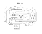
- Fig. 10 illustrates a conventional configuration of such package brake.
- a package brake having a substantially similar configuration to that of Fig. 10 is disclosed in JP,H10-25061,A .
- the package brake includes a cylindrical housing 101 having an opening and a bottom, a brake shoe 102 internally engaged with the front opening, and a bearing center 103 attached to a front end of the brake shoe 102.
- the brake shoe 102 and the bearing center 103 can individually move relative to the housing 101 in a front-back direction.
- the brake shoe 102 includes a shaft 104 to be inserted into the housing 101, a flange 105 externally extending from a front end portion of the shaft 104, and an external sleeve 106 extending in a rear direction from an outer circumferential edge of the flange 105.
- a friction material 107 for applying a braking force to the bearing center 103 is provided in a front surface of the flange 105.
- An air chamber 110 arranged to receive air from a compressor 109 via a solenoid valve 109a and an air inlet 108 is provided between a rear end portion of the shaft 104 and an inner end portion of the housing 101.
- a twisted-coil-shaped first spring 111 arranged to apply a biasing force to move the brake shoe 102 in a front direction is contained in the air chamber 110.
- Reference numeral 112 denotes a seal member that shields an inner surface of the housing 101 and an outer circumferential surface of the brake shoe 102.
- a hollow chamber 113 having a front opening is provided from an anteroposterior center to the front end portion of the shaft 104, and a shaft 114 of the bearing center is inserted into the hollow chamber 113.
- the bearing center 103 includes the shaft 114 and a holder portion 115 arranged on a front end of the shaft 114.
- a front surface of the holder portion 115 has a tapered shape and presses against a take-up tube 21 by proceeding into one side surface of the take-up tube 21.
- a second spring 116 is provided inside the hollow chamber 113 to press against the brake shoe 102 in the rear direction in a normal state in which the braking force is not applied.
- a bearing 117 is provided to a front end portion of the hollow chamber 113, and the bearing center 103 can rotate integrally with the take-up tube 21 via the bearing 117.
- the biasing force of the first spring 111 acts on the bearing center 103 in the normal state in which the braking force is not applied.
- the braking force is applied to the bearing center 103 to stop the take-up tube (winding package) from rotating. More specifically, when the working air is supplied to the inside of the air chamber 110, the shaft 104 of the brake shoe 102 is pressed in the front direction by the air pressure. Then, the friction material 107 of the brake shoe 102 makes contact with the holder portion 115 of the bearing center 103, and thus, the braking force is applied to the bearing center 103.
- the braking force (B) when the braking force (B) is increased, i.e., when the air pressure is increased, the suppress strength (f1) derived from the air pressure is also increased, and thus, the greater holding force (F2) acts on the take-up tube 21. As a result, the take-up tube 21 may be damaged. Such trouble can be eliminated by, for example, reducing the air pressure. However, when the air pressure is reduced, the surface pressure between the friction material 107 and the holder portion 115 is also reduced. Accordingly, the reduction of the braking force (B) cannot be prevented, and a longer period of time is required until the rotation of the winding package is stopped, which is disadvantageous.
- preferred embodiments of the present invention provide a package brake and an automatic winder including the package brake in which a braking force can be increased without excessively increasing a holding force for a take-up tube at the time of braking operation.
- a preferred embodiment of the present invention provides a package brake arranged to apply a braking force derived from fluid pressure to a winding package composed of a take-up tube and a yarn that is wound around a surface of the take-up tube.
- a holding member that holds one side surface of the take-up tube and an action member that applies a braking force by making contact with the holding member are attached to a cylindrical housing.
- the holding member and the action member can individually move with respect to the housing in a front direction towards the take-up tube and in a rear direction away from the take-up tube.
- the holding member is pressed in the front direction by a pressing element.
- a first acting force directed to the front direction towards the take-up tube and a second acting force in which the braking force is exerted between the action member and the holding member are applied to the action member and the holding member.
- the package brake includes the cylindrical housing, the cylindrical hollow action member that is attached to the housing such that the action member can move in the front-back direction, and the holding member that is attached to the housing and the action member such that the holding member can move in the front-back direction.
- the holding member includes a shaft axially supported by the action member and a take-up tube holding portion stretching at a front end of the shaft.
- the take-up tube holding portion can rotate integrally with the take-up tube around the shaft defined as a rotation axis. In a normal state, when the shaft receives a suppress strength directed to the front direction from the pressing element, a front surface of the take-up tube holding portion is pressed against the side surface of the take-up tube to hold the take-up tube.
- a friction material provided on a front side of the action member is pressed against the take-up tube holding portion, and thus, the braking force with respect to the holding member is exerted.
- a first fluid chamber and a second fluid chamber are provided to respectively receive the first acting force and the second acting force when the working fluid is supplied.
- the package brake includes the cylindrical housing, a cylindrical hollow holding member that is attached to the housing such that the holding member can move, and an action member that is attached such that the action member can move with respect to the housing and the holding member.
- the action member includes a shaft axially supported by the holding member and a brake shoe stretching at a front end of the shaft.
- a friction material arranged to exert a braking force with respect to the holding member is provided in a portion of the brake shoe.
- the holding member includes an inner sleeve attached inside the housing, an external sleeve arranged to be externally attached to and held by the housing, and an take-up tube holding portion arranged to hold the take-up tube.
- the take-up tube holding portion can rotate integrally with the take-up tube around the shaft defined as a rotation axis of the action member.
- a rear end portion of the inner sleeve receives a suppress strength directed to the front direction from the pressing element
- a front surface of the take-up tube holding portion is pressed against the side surface of the take-up tube to hold the take up tube.
- the action member is moved relative to the holding member by the second acting force, the friction material is pressed against the take-up tube holding portion, and the braking force is exerted with respect to the holding member.
- the first fluid chamber for receiving the first acting force when the working fluid is supplied is provided between the housing and the holding member, and the second fluid chamber for receiving the second acting force is provided between the action member and the holding member.
- the first fluid chamber and the second fluid chamber can be communicated with each other.
- the braking force applied to the holding member can be adjusted in accordance with a package radius of the winding package.
- the braking force applied to the holding member can be adjusted in accordance with a number of rotations per unit time of the winding package.
- the present invention relates to an automatic winder including the above package brake.
- the first acting force directed to the front direction towards the take-up tube and the second acting force in which the braking force is exerted between the action member and the holding member are applied to the action member and the holding member.
- the first acting force is applied to any one of the action member and the holding member, and the second acting force is applied to both the action member and the holding member.
- the action member and the holding member can be moved in the front-back direction. Therefore, the braking force derived from the second acting force can act on both the action member and the holding member. Accordingly, the braking force can be easily improved as compared with the conventional art in which the braking force is obtained only by moving the action member in the front direction.
- the second acting force influences the braking operation but does not influence the holding force with respect to the take-up tube at the time of braking operation. Accordingly, by increasing the second acting force, the increase of the holding force can be effectively controlled while increasing the braking force.
- the braking force can be reliably improved while controlling the increase of the holding force. Accordingly, problems that are inevitable in the conventional package brake, such as a damage of the take up tube due to the excessive holding force owing to the increase of the braking force, can be effectively eliminated.
- the action member is attached to the housing, the holding member includes the shaft axially supported by the action member and the take-up tube holding portion stretching at the front end of the shaft, and the braking force can be exerted with respect to the holding member when the action member is moved relative to the holding member by the second acting force.
- the first fluid chamber for receiving the first acting force and the second fluid chamber for receiving the second acting force are provided.
- the holding member is movably attached to the housing, the action member includes the shaft axially supported by the holding member and the brake shoe stretching at the front end of the shaft, and the braking force can be exerted with respect to the holing member when the action member is moved relative to the holding member by the second acting force and when the friction material is resultantly pressed against the take-up tube holding portion.
- the first fluid chamber for receiving the first acting force when the working fluid is supplied is provided between the housing and the holding member, and the second fluid chamber for receiving the second acting force is provided between the action member and the holding member.
- the braking force (second acting force) occurred in the second fluid chamber acts on the action member, and the suppress strength (first acting force) that occurs in the first fluid chamber and is directed to the take-up tube side acts on the holding member. Accordingly, at the time of braking operation, the braking force derived from the resultant force of the first and second acting forces can be reliably obtained. Moreover, the second acting force influences the braking operation but does not influence the holding force with respect to the take-up tube. Accordingly, the braking force can be increased while effectively preventing the damage of the take-up tube.
- the working fluid supplied to the first and second fluid chambers can be supplied from individually provided fluid supplying units (for example, compressors), however, the working fluid is preferably supplied from one fluid supplying unit to the fluid chambers in view of simplification of the unit.
- the fluid chambers are preferably communicated with each other, and thus, by opening one fluid inlet at the action member or the holding member, the working fluid can be supplied to both fluid chambers.
- the winding package When a number of rotations of the winding package is small, the winding package can be stopped by applying a small braking force, and when the number of rotations of the winding package is large, a larger braking force is required. Therefore, when the braking force applied to the holding member can be adjusted in accordance with the number of rotations of the winding package, the proper braking force can be applied to stop the winding package. As a result, the damage of the take-up tube due to the excessive holding force applied to the take-up tube can be effectively prevented.
- Fig. 1 is a schematic configuration diagram of a package brake according to a first embodiment of the present invention.
- Fig. 2 is a schematic configuration diagram of an automatic winder.
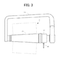
- Fig. 3 is a diagram used to explain a holding mechanism of a winding package.
- Fig. 4 is a diagram used to explain a holding force of the package brake in a normal state according to the first embodiment of the present invention.
- Fig. 5 is a diagram used to explain the holding force and a braking force at the time of braking operation of the package brake according to the first embodiment of the present invention.
- Fig. 6 is a schematic configuration diagram of the package brake according to a second embodiment of the present invention.
- Fig. 7 is a diagram used to explain the holding force of the package brake in the normal state according to the second embodiment of the present invention.
- Fig. 8 is a diagram used to explain the holding force and the braking force at the time of braking operation of the package brake according to the second embodiment of the present invention.
- Fig. 9 is a schematic configuration diagram of the package brake according to a modified example of the present invention.
- Fig. 10 is a schematic configuration diagram of a conventional package brake.
- Figs. 1 through 5 illustrate an embodiment in which a package brake of the present invention is applied to a winding unit of an automatic winder.
- a winding unit 1 includes a guide 3 arranged to guide a yarn Y from a yarn feeding bobbin 2, a tension applying device 4 arranged to apply a proper tension to the yarn Y, a yarn joining device 5, and a yarn defect clearing device 6 arranged to detect a defect of the yarn Y, or the like, which are aligned from a lower portion to an upper portion of the unit.
- a yarn guide pipe 12 and a suction mouth 13 arranged to suck and catch a broken yarn and transfer the caught yarn to the yarn joining device 5 are provided in a midway portion of a line of the above elements such that the yarn guide pipe 12 and the suction mouth 13 can vertically swing.
- the yarn Y fed from the yarn feeding bobbin 2 is checked whether or not the yarn Y has a defect.
- the yarn Y is cut by a cutter provided in the yarn defect clearing device 6, and a yarn defect portion is sucked and removed.
- the package brake 11 When working air (working fluid) is supplied from a compressor 20, the package brake 11 applies a braking force to a take-up tube 21 of the winding package 9.
- a solenoid valve 24 arranged to be turned on/off by a control circuit 23 is provided in a midway portion of a flow path 22 ranging from the compressor 20 to the package brake 11.
- the take-up tube 21 has a larger radius on a rear end side that is held by the package brake 11, and is tapered off with the radius being gradationally reduced towards a front side.
- the package brake 11 includes, as constituent elements, a cylindrical housing 30 having a bottom and a front opening 30a, a holding member 31 arranged to hold the take-up tube 21 by pressing a rear end portion of the take-up tube 21 towards a front side, an action member 32 arranged to apply a braking force by making contact with the holding member 31, a first spring 33 (pressing element) arranged to bias the holding member 31 in a front direction, and a second spring 34 arranged to apply a biasing force to separate the action member 32 and the holding member 31 from each other in a normal state, or the like.
- the action member 32 includes a flange 40 stretching around a circumferential surface on a side that is close to a front end, an inner sleeve 41 arranged to be inserted into the housing 30 from the front opening 30a, and an external sleeve 42 extending from a leading end portion of the flange 40 in a front-back direction.
- the action member 32 is arranged such that a slight interspace E occurs between an outer circumferential surface of the inner sleeve 41 and an inner circumferential surface of the housing 30.
- Reference numeral 43 denotes a ring-shaped seal member that is embedded in and fixed to an inner wall surface of the inner sleeve 41.
- the external sleeve 42 is cylindrically shaped and has an opening in an axial direction.
- An air inlet 45 that allows working air to flow from the compressor 20 is arranged through the external sleeve 42.
- a minor diameter of the external sleeve 42 is set to be greater than a major diameter of the housing 30 so that the external sleeve 42 can non-rotationally move in the front-back direction along an outer circumferential surface of the housing 30.
- a friction material 46 made of rubber is embedded in a front end portion of the external sleeve 42.
- the friction material 46 has a ring shape with a front end side being obliquely cut out.
- a front end oblique surface 46a makes contact with a facing wall surface of the holding member 31.
- a ring-shaped seal member 47 arranged to hermetically seal an interspace generated between the outer circumferential surface of the housing 30 and the external sleeve 42 is embedded in a rear end portion of the external sleeve 42.
- the holding member 31 includes a shaft 50 arranged to penetrate through the inner sleeve 41 in the front-back direction, a bearing 51 arranged at a front end portion of the shaft 50, and a bearing center (take-up tube holding portion) 52 that is rotationally attached via the bearing 51.
- the shaft 50 includes a main body 50a, a bearing supporting portion 50b consecutively provided to a front end portion of the shaft main body 50a, and a flanged spring retainer portion 50c stretching at a rear end portion of the shaft main body 50a.
- a twisted-coil-shaped first spring 33 is arranged in contact with the spring retainer portion 50c, and the entire holding member 31 is always biased in the front direction by the first spring 33.
- a ring-shaped seal member 54 is embedded in an outer circumferential surface of the spring retainer portion 50c, and the inside of the housing 30 is separated by the seal member 54 into a second air chamber 65 (to be described later) on a front side and a spring chamber 55 on a rear side.
- the bearing 51 is attached to the bearing supporting portion 50b.
- a second spring 34 which provides a repulsive force when the action member 32 and the holding member 31 comes closer to each other than a prescribed distance, is provided between a front end surface of the inner sleeve 41 of the action member 32 and the bearing 51.
- the bearing center 52 includes a cylindrical shaft portion 60 supported by the bearing 51 and a holder portion 61 stretching from a front end of the cylindrical shaft portion 60.
- a front surface of the holder portion 61 is tapered.
- a rear surface of the holder portion 61 is a posterosuperiorly tapered surface that matches an inclination angle of a tapered surface of the friction material 46.
- a notable point in the package brake 11 according to the present embodiment is that, when working air is supplied to the inside of the unit from the air inlet 45 in order to obtain a braking force, a first acting force (f1) that presses the action member 32 towards a take-up tube side and a second acting force (f2) that presses the action member 32 in a direction in which the holder portion 61 of the holding member 31 and the friction material 46 of the action member 32 make contact with each other are applied ( Fig. 5 ). More specifically, a first air chamber (first fluid chamber) 64 and a second air chamber (second fluid chamber) 65 communicated with the first air chamber 64 are provided inside the unit composed of the housing 30, the action member 32, and the holding member 31.
- the first air chamber 64 When the working air is supplied from the air inlet 45, the first air chamber 64 is provided with the first acting force (f1) that presses the action member 32 towards the take-up tube 21, and the second air chamber 65 is provided with the second acting force (f2) that presses the action member 32 in the direction in which the holder portion 61 of the holding member 31 and the friction material 46 of the action member 32 make contact with each other.
- the first air chamber 64 is provided in a gap portion separated by the outer circumferential surface of the inner sleeve 41 of the action member 32, an inner circumferential surface of the external sleeve 42, and a rear surface of the flange 40.
- the second air chamber 65 is provided in a gap portion separated by a front surface of the spring retainer portion 50c of the holding member 31, the inner circumferential surface of the housing 30, and a rear end surface of the inner sleeve 41 of the action member 32.
- the first and second air chambers 64 and 65 are communicated with each other via the interspace E arranged between the outer circumferential surface of the inner sleeve 41 and the inner circumferential surface of the housing 30.
- the first acting force (f1) which is derived from the air pressure that presses the rear surface of the flange 40 towards the take-up tube side
- the second acting force (f2) which is derived from the air pressure that presses to separate the spring retainer portion 50c of the holding member 31 and the inner sleeve 41 of the action member 32 from each other, act on both the holding member 31 and the action member 32.
- a suppress strength (A) derived from the biasing force of the first spring 33 acts on the take-up tube 21 in the normal state in which the braking force is not applied.
- the suppress strength (A) corresponds to a holding force (F1) for the take-up tube 21 in the normal state.
- a value obtained by subtracting a suppress strength (R) of the second spring 34 from a resultant force of the first acting force (f1) and the second acting force (f2) acts as a surface pressure (B: braking force) between the action member 32 (friction material 46) and the holding member 31 (holder portion 61) at the time of braking operation (B f1+f2-R).
- both the suppress strength (A) and the first acting force (f1) act on the take-up tube 21 as the holding force (F2) at the time of braking operation, and the braking force (B: surface pressure) based on the resultant force of the first acting force (f1) and the second acting force (f2) can be exerted.
- the braking force (B) can be increased without excessively increasing the holding force (F2) for the take-up tube 21 at the time of braking operation.
- the braking force (B) when the first acting force (f1) is increased in order to increase the braking force (B), the first acting force (f1) directly acts on the holding force (F2), the holding force (F2) is inevitably increased, and the take-up tube 21 may be damaged.
- the package brake 11 according to the present embodiment not only the first acting force (f1) but also the braking force (B) derived from the resultant force of the first acting force (f1) and the second acting force (f2) acts on between the action member 32 and the holding member 31. Therefore, the braking force (B) can be easily increased. Accordingly, while controlling the increase of the holding force (F2) for the take up tube 21 at the time of braking operation, the braking force (B) can be increased.
- the braking force (B) applied to the holding member 31 can be adjusted in accordance with a package radius of the winding package 9.
- a package radius of the winding package 9 by providing a sensor that detects the package radius of the winding package 9, and by adjusting an amount of the working air to be supplied to the package brake 11 by the solenoid valve 24 based on a detected value of the sensor, the braking force (B) can be adjusted to be larger or smaller.
- the package radius is small, a determination is made that a weight of the winding package 9 is small, and thus, a small amount of braking force is applied.
- the package radius is large, a determination is made that the weight of the winding package 9 is large, and thus, a large amount of braking force is applied.
- a proper amount of braking force (B) can be applied to stop the winding package 9.
- a load i.e., holding force (F2)
- holding force (F2) on the take-up tube 21 can be prevented from being excessive, and thus, the damage of the take-up tube 21 can be effectively prevented.
- the braking force (B) applied to the holding member 31 may be adjusted by the solenoid valve 24 in accordance with a number of rotations of the winding package 9.
- a proper amount of braking force (B) can be applied to stop the winding package 9.
- the load (holding force (F2)) on the take-up tube 21 can also be prevented from being excessive, and thus, the damage of the take-up tube 21 can be effectively prevented.
- Figs. 6 through 8 illustrate a second embodiment of the package brake of the present invention.
- the package brake 11 includes, as constituent elements, the cylindrical housing 30 having the bottom and the front opening 30a, a holding member 31 arranged to hold the take-up tube 21 by pressing the rear end side of the take-up tube 21 towards the front side, a action member 32 arranged to apply the braking force by making contact with the holding member 31, and the first spring 33 arranged to bias the holding member 31 in the front direction.
- the holding member 31 includes a flange 70 stretching around a circumferential surface on a side that is close to the front end, an inner sleeve 71 arranged to be inserted into the housing 30 from the front opening 30a, an external sleeve 42 extending from a leading end portion of the flange 70 in a rear direction, and the bearing center (take-up tube holding portion) 52 arranged to rotate via the bearing 51 attached to a front end portion of the inner sleeve 71.
- the inner sleeve 71 is cylindrically shaped and has an opening at a front portion and a rear portion.
- Reference numeral 73 denotes a ring-shaped seal member that is embedded in and fixed to an inner surface of the inner sleeve 71.
- the external sleeve 72 is cylindrically shaped and has an opening at a rear portion.
- An air inlet 74 that allows working air to flow from the compressor 20 is arranged through the external sleeve 72.
- a minor diameter of the external sleeve 72 is set to be greater than the major diameter of the housing 30 so that the external sleeve 72 can non-rotationally move in the front-back direction along the outer circumferential surface of the housing 30.
- a ring-shaped seal member 75 arranged to hermetically seal an interspace generated between the outer circumferential surface of the housing 30 and the external sleeve 72 is embedded in a rear end portion of the external sleeve 72.
- the bearing center 52 includes a cylindrical shaft portion 76 to which the bearing 51 is attached and a holder portion 77 stretching around an outer circumferential surface of the cylindrical shaft portion 76.
- the bearing center 52 can rotate with respect to the front end of the inner sleeve 71.
- a front surface of the holder portion 77 is tapered off.
- the action member 32 includes a shaft 80 arranged to penetrate through the inner sleeve 71 in the front-back direction and a brake shoe 81 attached to a front end portion of the shaft 80.
- the action member 32 can non-rotationally move in the front-back direction with respect to the housing 30.
- An outer shape of the shaft 80 has a substantially similar size to a size of the minor diameter of the inner sleeve 71.
- the shaft 80 includes a shaft main body 80a arranged to be internally engaged with the inner sleeve 71 and a flanged spring retainer portion 80b stretching at a rear end portion of the shaft main body 80a.
- the twisted-coil-shaped first spring 33 is arranged in contact with the spring retainer portion 80b, and the holding member 31 is always biased in the front direction by the first spring 33.
- the entire action member 32 is moved in the front direction by the biasing force of the first spring 33, the holder portion 77 is resultantly pressed in the front direction by the movement of the action member 32, and thus, the holding member 31 is biased in the front direction.
- a ring-shaped seal member 83 is embedded in an outer circumferential surface of the spring retainer portion 80b, and the inside of the housing 30 is separated by the seal member 83 into the second air chamber 65 on the front side and the spring chamber 55 on the rear side.
- the brake shoe 81 has a disk shape with an opening at a center and is fixed to a leading end of the shaft main body 80a.
- a friction material 46 made of rubber is embedded in a rear end surface of the brake shoe 81.
- the friction material 46 has a ring shape with a rear end side being obliquely cut out.
- a rear end oblique surface 46b makes contact with a facing wall surface of the holder portion 77 of the holding member 31.
- a notable point in the package brake 11 according to the present embodiment is that, when working air is supplied to the inside of the unit from the air inlet 74 in order to obtain a braking force, in addition to the first acting force (f1) that presses the holding member 31 towards the take-up tube side, the second acting force (f2) is applied to relatively move the holding member 31 and the action member 32 in a direction in which the holder portion 77 and the friction material 46 make contact with each other. More specifically, the first air chamber 64 and the second air chamber 65 communicated with the first air chamber 64 are provided inside the unit composed of the housing 30, the action member 32, and the holding member 31.
- the first air chamber 64 When working air is supplied from the air inlet 74, the first air chamber 64 is provided with the first acting force (f1) that presses the holding member 31 towards the take-up tube 21, and the second air chamber 65 is provided with the second acting force (f2) that presses in the direction in which the holder portion 77 of the holding member 31 and the friction material 46 of the action member 32 make contact with each other.
- the first air chamber 64 is provided in a gap portion separated by the outer circumferential surface of the inner sleeve 71 of the holding member 31, an inner circumferential surface of the external sleeve 72, and a rear surface of the flange 70.
- the second air chamber 65 is provided in a gap portion separated by a front surface of the spring retainer portion 80b, the inner circumferential surface of the housing 30, and a rear end surface of the inner sleeve 71 of the holding member 31.
- the first and second air chambers 64 and 65 are communicated with each other via the interspace E arranged between the outer circumferential surface of the inner sleeve 71 and the inner circumferential surface of the housing 30.
- the first acting force (f1) which is derived from the air pressure that presses the a rear surface of the flange 70 of the holding member 31 in the front direction
- the second acting force (f2) which is derived from the air pressure that presses to separate the spring retainer portion 80b of the action member 32 and the inner sleeve 71 of the action member 32 from each other, act on both the holding member 31 and the action member 32 ( Fig. 8 ).
- a suppress strength (A) derived from the biasing force of the first spring 33 acts on the take-up tube 21 in the normal state in which the braking force is not applied.
- the suppress strength (A) corresponds to a holding force (F1) for the take-up tube 21 in the normal state.
- the resultant force of the suppress strength (A) and the first acting force (f1) act on the take-up tube 21 as the holding force (F2) at the time of braking operation, and the force obtained by subtracting the suppress strength (A) of the first spring 33 from the second acting force (f2) acts as the braking force (B: surface pressure) between the action member 32 and the holding member 31.
- the braking force (B) can be increased without excessively increasing the holding force (F2) for the take-up tube 21 at the time of braking operation.
- the braking force (B) derived from the second acting force (f2) different from the first acting force (f1) acts between the action member 32 and the holding member 31.
- the holding force (F2) and the braking force (B) can be easily distinguished, and the braking force (B) can be easily increased.
- the second acting force (f2) is not influenced, the braking force (B) can be increased while controlling the increase of the holding force (F2) for the take-up tube 21 at the time of braking operation.
- the braking force (B) applied to the holding member 31 can be adjusted in accordance with a package radius of the winding package 9.
- a package radius of the winding package 9 by providing a sensor that detects the package radius of the winding package 9, and by adjusting an amount of the working air to be supplied to the package brake 11 by the solenoid valve 24 based on a detected value of the sensor, the braking force (B) can be adjusted to be larger or smaller.
- the package radius is small, a determination is made that a weight of the winding package 9 is small, and thus, a small amount of braking force is applied.
- the package radius is large, a determination is made that the weight of the winding package 9 is large, and thus, a large amount of braking force is applied.
- a proper amount of braking force (B) can be applied to stop the winding package 9.
- a load i.e., holding force (F2)
- holding force (F2) on the take-up tube 21 can be prevented from being excessive, and thus, the damage of the take-up tube 21 can be effectively prevented.
- the braking force (B) applied to the holding member 31 may be adjusted by the solenoid valve 24 in accordance with a number of rotations of the winding package 9.
- a proper amount of braking force (B) can be applied to stop the winding package 9.
- the load (holding force (F2)) on the take-up tube 21 can also be prevented from being excessive, and thus, the damage of the take-up tube 21 can be effectively prevented.
- Fig. 9 illustrates a modified example of the present invention.
- the first spring 33 defined as a pressing element in the first embodiment may be omitted, and the suppress strength (A) can be obtained from the working air.
- the suppress strength (A) can be obtained from the working air.
- the suppress strength (A) that presses the holding member 31 in the front direction may be applied.
- the working air is supplied only to the third air chamber 90 in the normal state, and the take-up tube 21 may be held by the holding member 31 through the suppress strength (A) derived from such working air.
- the solenoid valves 24a and 24b are opened, and the working air is supplied to the first, second, and third air chambers 64, 65, 90.
- Other points are similar to the first embodiment.
- the air chambers 64 and 65 are communicated via the interspace E, however, the present invention is not limited to such configuration, and each of the air chambers 64, 65 may be provided with an air inlet so that the working air is individually supplied to the air chambers 64, 65.
- the first and second acting forces are obtained from the working air, however, the present invention is not limited to such configuration, and acting forces may be obtained from, for example, hydraulic pressure.
Landscapes
- Engineering & Computer Science (AREA)
- Textile Engineering (AREA)
- Unwinding Webs (AREA)
- Tension Adjustment In Filamentary Materials (AREA)
- Registering, Tensioning, Guiding Webs, And Rollers Therefor (AREA)
- Braking Arrangements (AREA)
- Winding Of Webs (AREA)
- Winding Filamentary Materials (AREA)
Abstract
Description
- The present invention relates to a package brake and an automatic winder including the package brake arranged to apply a braking force derived from fluid pressure to a winding package composed of a take-up tube that is rotationally driven and a yarn that is wound around a surface of the take-up tube.
- Conventionally, a winding unit of an automatic winder defined as a winding apparatus includes a package brake arranged to apply a braking force to a winding package rotated by a traversing drum.
Fig. 10 illustrates a conventional configuration of such package brake. A package brake having a substantially similar configuration to that ofFig. 10 is disclosed inJP,H10-25061,A - As illustrated in
Fig. 10 , the package brake includes acylindrical housing 101 having an opening and a bottom, abrake shoe 102 internally engaged with the front opening, and a bearing center 103 attached to a front end of thebrake shoe 102. Thebrake shoe 102 and the bearing center 103 can individually move relative to thehousing 101 in a front-back direction. Thebrake shoe 102 includes ashaft 104 to be inserted into thehousing 101, aflange 105 externally extending from a front end portion of theshaft 104, and an external sleeve 106 extending in a rear direction from an outer circumferential edge of theflange 105. Afriction material 107 for applying a braking force to the bearing center 103 is provided in a front surface of theflange 105. Anair chamber 110 arranged to receive air from a compressor 109 via a solenoid valve 109a and anair inlet 108 is provided between a rear end portion of theshaft 104 and an inner end portion of thehousing 101. A twisted-coil-shaped first spring 111 arranged to apply a biasing force to move thebrake shoe 102 in a front direction is contained in theair chamber 110.Reference numeral 112 denotes a seal member that shields an inner surface of thehousing 101 and an outer circumferential surface of thebrake shoe 102. - A
hollow chamber 113 having a front opening is provided from an anteroposterior center to the front end portion of theshaft 104, and a shaft 114 of the bearing center is inserted into thehollow chamber 113. The bearing center 103 includes the shaft 114 and a holder portion 115 arranged on a front end of the shaft 114. A front surface of the holder portion 115 has a tapered shape and presses against a take-up tube 21 by proceeding into one side surface of the take-up tube 21. Asecond spring 116 is provided inside thehollow chamber 113 to press against thebrake shoe 102 in the rear direction in a normal state in which the braking force is not applied. A bearing 117 is provided to a front end portion of thehollow chamber 113, and the bearing center 103 can rotate integrally with the take-up tube 21 via the bearing 117. - In such package brake, the biasing force of the first spring 111 acts on the bearing center 103 in the normal state in which the braking force is not applied. In other words, the bearing center 103 is pressed in the front direction by the biasing force (A) of the first spring 111, and the take-
up tube 21 is held by such suppress strength defined as a holding force (holding force F1=A). - When working air is supplied from the compressor 109 to the inside of the
air chamber 110 via theair inlet 108, the braking force is applied to the bearing center 103 to stop the take-up tube (winding package) from rotating. More specifically, when the working air is supplied to the inside of theair chamber 110, theshaft 104 of thebrake shoe 102 is pressed in the front direction by the air pressure. Then, thefriction material 107 of thebrake shoe 102 makes contact with the holder portion 115 of the bearing center 103, and thus, the braking force is applied to the bearing center 103. At this time, a resultant force of the biasing force (A) derived from the first spring 111 and the suppress strength (f1) derived from the air pressure acts on the take-up tube 21, and the take-up tube 21 is thus held by the resultant force (holding force F2=A+f1). Moreover, a surface pressure, which is obtained by subtracting a biasing force (R) of thesecond spring 116 from a resultant force of the biasing force (A) derived from the first spring 111 and the suppress strength (f1) derived from the air pressure, acts between thefriction material 107 and the holder portion 115, and thus, the braking force (B) is applied to the bearing center 103 (B=A+f1-R). - Therefore, when the braking force (B) is increased, i.e., when the air pressure is increased, the suppress strength (f1) derived from the air pressure is also increased, and thus, the greater holding force (F2) acts on the take-
up tube 21. As a result, the take-up tube 21 may be damaged. Such trouble can be eliminated by, for example, reducing the air pressure. However, when the air pressure is reduced, the surface pressure between thefriction material 107 and the holder portion 115 is also reduced. Accordingly, the reduction of the braking force (B) cannot be prevented, and a longer period of time is required until the rotation of the winding package is stopped, which is disadvantageous. - In order to overcome the problems of the above conventional package brake, preferred embodiments of the present invention provide a package brake and an automatic winder including the package brake in which a braking force can be increased without excessively increasing a holding force for a take-up tube at the time of braking operation.
- A preferred embodiment of the present invention provides a package brake arranged to apply a braking force derived from fluid pressure to a winding package composed of a take-up tube and a yarn that is wound around a surface of the take-up tube. In the package brake, a holding member that holds one side surface of the take-up tube and an action member that applies a braking force by making contact with the holding member are attached to a cylindrical housing. When working fluid is received, the holding member and the action member can individually move with respect to the housing in a front direction towards the take-up tube and in a rear direction away from the take-up tube. In a state in which the braking force is not applied, the holding member is pressed in the front direction by a pressing element. By receiving the working fluid, a first acting force directed to the front direction towards the take-up tube and a second acting force in which the braking force is exerted between the action member and the holding member are applied to the action member and the holding member.
- More specifically, the package brake includes the cylindrical housing, the cylindrical hollow action member that is attached to the housing such that the action member can move in the front-back direction, and the holding member that is attached to the housing and the action member such that the holding member can move in the front-back direction. The holding member includes a shaft axially supported by the action member and a take-up tube holding portion stretching at a front end of the shaft. The take-up tube holding portion can rotate integrally with the take-up tube around the shaft defined as a rotation axis. In a normal state, when the shaft receives a suppress strength directed to the front direction from the pressing element, a front surface of the take-up tube holding portion is pressed against the side surface of the take-up tube to hold the take-up tube. When the action member is moved relative to the holding member by the second acting force, a friction material provided on a front side of the action member is pressed against the take-up tube holding portion, and thus, the braking force with respect to the holding member is exerted. A first fluid chamber and a second fluid chamber are provided to respectively receive the first acting force and the second acting force when the working fluid is supplied.
- The package brake according to an embodiment of the present invention includes the cylindrical housing, a cylindrical hollow holding member that is attached to the housing such that the holding member can move, and an action member that is attached such that the action member can move with respect to the housing and the holding member. The action member includes a shaft axially supported by the holding member and a brake shoe stretching at a front end of the shaft. A friction material arranged to exert a braking force with respect to the holding member is provided in a portion of the brake shoe. The holding member includes an inner sleeve attached inside the housing, an external sleeve arranged to be externally attached to and held by the housing, and an take-up tube holding portion arranged to hold the take-up tube. The take-up tube holding portion can rotate integrally with the take-up tube around the shaft defined as a rotation axis of the action member. In a normal state, when a rear end portion of the inner sleeve receives a suppress strength directed to the front direction from the pressing element, a front surface of the take-up tube holding portion is pressed against the side surface of the take-up tube to hold the take up tube. When the action member is moved relative to the holding member by the second acting force, the friction material is pressed against the take-up tube holding portion, and the braking force is exerted with respect to the holding member. The first fluid chamber for receiving the first acting force when the working fluid is supplied is provided between the housing and the holding member, and the second fluid chamber for receiving the second acting force is provided between the action member and the holding member.
- The first fluid chamber and the second fluid chamber can be communicated with each other.
- The braking force applied to the holding member can be adjusted in accordance with a package radius of the winding package.
- The braking force applied to the holding member can be adjusted in accordance with a number of rotations per unit time of the winding package.
- The present invention relates to an automatic winder including the above package brake.
- In the package brake according to an embodiment of the present invention, when working fluid is supplied, the first acting force directed to the front direction towards the take-up tube and the second acting force in which the braking force is exerted between the action member and the holding member are applied to the action member and the holding member. In other words, when the working fluid is supplied, the first acting force is applied to any one of the action member and the holding member, and the second acting force is applied to both the action member and the holding member.
- Thus, when the working fluid is supplied, the action member and the holding member can be moved in the front-back direction. Therefore, the braking force derived from the second acting force can act on both the action member and the holding member. Accordingly, the braking force can be easily improved as compared with the conventional art in which the braking force is obtained only by moving the action member in the front direction.
In addition, the second acting force influences the braking operation but does not influence the holding force with respect to the take-up tube at the time of braking operation. Accordingly, by increasing the second acting force, the increase of the holding force can be effectively controlled while increasing the braking force. - As described above, in the package brake according to the embodiment of the present invention, when the working fluid is supplied, not only the acting force (i.e., the first acting force) directed to the direction of the take-up tube but also the acting force (i.e., the second acting force) exerting the braking force is exerted, and thus, the braking force can be reliably improved while controlling the increase of the holding force. Accordingly, problems that are inevitable in the conventional package brake, such as a damage of the take up tube due to the excessive holding force owing to the increase of the braking force, can be effectively eliminated.
- More specifically, the action member is attached to the housing, the holding member includes the shaft axially supported by the action member and the take-up tube holding portion stretching at the front end of the shaft, and the braking force can be exerted with respect to the holding member when the action member is moved relative to the holding member by the second acting force. The first fluid chamber for receiving the first acting force and the second fluid chamber for receiving the second acting force are provided.
- Accordingly, when the working fluid is supplied at the time of braking operation, the suppress strength (first acting force) that occurs in the first fluid chamber and is directed to the take-up tube side and the suppress strength (second acting force) that occurs in the second fluid chamber and relatively moves the friction material of the action member in a direction in which the friction material makes contact with the holding member act on the action member. Accordingly, a large braking force which is derived from a resultant force of the first acting force and the second acting force can be reliably obtained at the time of braking operation. Moreover, since the braking force by the second acting force does not act as a force that presses the take-up tube, the holding force with respect to the take-up tube can be prevented from being excessive. Accordingly, the braking force can be increased while effectively preventing the damage of the take-up tube.
- The holding member is movably attached to the housing, the action member includes the shaft axially supported by the holding member and the brake shoe stretching at the front end of the shaft, and the braking force can be exerted with respect to the holing member when the action member is moved relative to the holding member by the second acting force and when the friction material is resultantly pressed against the take-up tube holding portion. The first fluid chamber for receiving the first acting force when the working fluid is supplied is provided between the housing and the holding member, and the second fluid chamber for receiving the second acting force is provided between the action member and the holding member.
- Thus, when the working fluid is supplied at the time of braking operation, the braking force (second acting force) occurred in the second fluid chamber acts on the action member, and the suppress strength (first acting force) that occurs in the first fluid chamber and is directed to the take-up tube side acts on the holding member. Accordingly, at the time of braking operation, the braking force derived from the resultant force of the first and second acting forces can be reliably obtained. Moreover, the second acting force influences the braking operation but does not influence the holding force with respect to the take-up tube. Accordingly, the braking force can be increased while effectively preventing the damage of the take-up tube.
- The working fluid supplied to the first and second fluid chambers can be supplied from individually provided fluid supplying units (for example, compressors), however, the working fluid is preferably supplied from one fluid supplying unit to the fluid chambers in view of simplification of the unit. In such a case, the fluid chambers are preferably communicated with each other, and thus, by opening one fluid inlet at the action member or the holding member, the working fluid can be supplied to both fluid chambers.
- When a great number of yarns are wound around the take-up tube, increasing the package radius, and when a weight of the winding package is resultantly increase, a large braking force is required to stop the winding package. By contraries, when the package radius is small, the weight of the winding package is also small, and thus, a small braking force can stop the winding package. Accordingly, when the braking force applied to the holding member can be adjusted in accordance with the package radius of the winding package, a proper braking force can be applied to stop the winding package. Thus, a load on the take-up tube can be prevented from being excessive, and the damage of the take-up tube can also be effectively prevented.
- When a number of rotations of the winding package is small, the winding package can be stopped by applying a small braking force, and when the number of rotations of the winding package is large, a larger braking force is required. Therefore, when the braking force applied to the holding member can be adjusted in accordance with the number of rotations of the winding package, the proper braking force can be applied to stop the winding package. As a result, the damage of the take-up tube due to the excessive holding force applied to the take-up tube can be effectively prevented.
- By providing the automatic winder with the above package brake, the reliability of the automatic winder can be improved.
- Other features, elements, processes, steps, characteristics and advantages of the present invention will become more apparent from the following detailed description of preferred embodiments of the present invention with reference to the attached drawings.
-
Fig. 1 is a schematic configuration diagram of a package brake according to a first embodiment of the present invention. -
Fig. 2 is a schematic configuration diagram of an automatic winder. -
Fig. 3 is a diagram used to explain a holding mechanism of a winding package. -
Fig. 4 is a diagram used to explain a holding force of the package brake in a normal state according to the first embodiment of the present invention. -
Fig. 5 is a diagram used to explain the holding force and a braking force at the time of braking operation of the package brake according to the first embodiment of the present invention. -
Fig. 6 is a schematic configuration diagram of the package brake according to a second embodiment of the present invention. -
Fig. 7 is a diagram used to explain the holding force of the package brake in the normal state according to the second embodiment of the present invention. -
Fig. 8 is a diagram used to explain the holding force and the braking force at the time of braking operation of the package brake according to the second embodiment of the present invention. -
Fig. 9 is a schematic configuration diagram of the package brake according to a modified example of the present invention. -
Fig. 10 is a schematic configuration diagram of a conventional package brake. -
Figs. 1 through 5 illustrate an embodiment in which a package brake of the present invention is applied to a winding unit of an automatic winder. As illustrated inFig. 2 , a windingunit 1 includes aguide 3 arranged to guide a yarn Y from ayarn feeding bobbin 2, atension applying device 4 arranged to apply a proper tension to the yarn Y, a yarn joining device 5, and a yarn defect clearing device 6 arranged to detect a defect of the yarn Y, or the like, which are aligned from a lower portion to an upper portion of the unit. - A traversing drum 7 arranged to traverse the yarn Y within a constant width, a guide plate 8 facing a traverse area of the traversing drum 7, a cradle 10 (
Fig. 3 ) arranged to axially support a winding package 9 such that the winding package 9 can rotate, and apackage brake 11 arranged to apply a braking force to the wining package 9, or the like, are provided in a front and upper portion of the unit. In addition to these constituent elements, ayarn guide pipe 12 and a suction mouth 13 arranged to suck and catch a broken yarn and transfer the caught yarn to the yarn joining device 5 are provided in a midway portion of a line of the above elements such that theyarn guide pipe 12 and the suction mouth 13 can vertically swing. When passing through the yarn defect clearing device 6, the yarn Y fed from theyarn feeding bobbin 2 is checked whether or not the yarn Y has a defect. When a yarn defect is detected, the yarn Y is cut by a cutter provided in the yarn defect clearing device 6, and a yarn defect portion is sucked and removed. - When working air (working fluid) is supplied from a
compressor 20, thepackage brake 11 applies a braking force to a take-uptube 21 of the winding package 9. Asolenoid valve 24 arranged to be turned on/off by a control circuit 23 is provided in a midway portion of aflow path 22 ranging from thecompressor 20 to thepackage brake 11. As illustrated inFig. 3 , the take-uptube 21 has a larger radius on a rear end side that is held by thepackage brake 11, and is tapered off with the radius being gradationally reduced towards a front side. - As illustrated in
Fig. 1 , thepackage brake 11 includes, as constituent elements, acylindrical housing 30 having a bottom and a front opening 30a, a holdingmember 31 arranged to hold the take-uptube 21 by pressing a rear end portion of the take-uptube 21 towards a front side, anaction member 32 arranged to apply a braking force by making contact with the holdingmember 31, a first spring 33 (pressing element) arranged to bias the holdingmember 31 in a front direction, and asecond spring 34 arranged to apply a biasing force to separate theaction member 32 and the holdingmember 31 from each other in a normal state, or the like. - The
action member 32 includes aflange 40 stretching around a circumferential surface on a side that is close to a front end, aninner sleeve 41 arranged to be inserted into thehousing 30 from the front opening 30a, and an external sleeve 42 extending from a leading end portion of theflange 40 in a front-back direction. Theaction member 32 is arranged such that a slight interspace E occurs between an outer circumferential surface of theinner sleeve 41 and an inner circumferential surface of thehousing 30. Reference numeral 43 denotes a ring-shaped seal member that is embedded in and fixed to an inner wall surface of theinner sleeve 41. - The external sleeve 42 is cylindrically shaped and has an opening in an axial direction. An air inlet 45 that allows working air to flow from the
compressor 20 is arranged through the external sleeve 42. A minor diameter of the external sleeve 42 is set to be greater than a major diameter of thehousing 30 so that the external sleeve 42 can non-rotationally move in the front-back direction along an outer circumferential surface of thehousing 30. Afriction material 46 made of rubber is embedded in a front end portion of the external sleeve 42. Thefriction material 46 has a ring shape with a front end side being obliquely cut out. At the time of braking operation, a front end oblique surface 46a makes contact with a facing wall surface of the holdingmember 31. A ring-shaped seal member 47 arranged to hermetically seal an interspace generated between the outer circumferential surface of thehousing 30 and the external sleeve 42 is embedded in a rear end portion of the external sleeve 42. - The holding
member 31 includes a shaft 50 arranged to penetrate through theinner sleeve 41 in the front-back direction, a bearing 51 arranged at a front end portion of the shaft 50, and a bearing center (take-up tube holding portion) 52 that is rotationally attached via the bearing 51. The shaft 50 includes a main body 50a, a bearing supporting portion 50b consecutively provided to a front end portion of the shaft main body 50a, and a flanged spring retainer portion 50c stretching at a rear end portion of the shaft main body 50a. A twisted-coil-shapedfirst spring 33 is arranged in contact with the spring retainer portion 50c, and the entire holdingmember 31 is always biased in the front direction by thefirst spring 33. A ring-shaped seal member 54 is embedded in an outer circumferential surface of the spring retainer portion 50c, and the inside of thehousing 30 is separated by the seal member 54 into a second air chamber 65 (to be described later) on a front side and a spring chamber 55 on a rear side. - The bearing 51 is attached to the bearing supporting portion 50b. A
second spring 34, which provides a repulsive force when theaction member 32 and the holdingmember 31 comes closer to each other than a prescribed distance, is provided between a front end surface of theinner sleeve 41 of theaction member 32 and the bearing 51. - The bearing center 52 includes a cylindrical shaft portion 60 supported by the bearing 51 and a
holder portion 61 stretching from a front end of the cylindrical shaft portion 60. A front surface of theholder portion 61 is tapered. A rear surface of theholder portion 61 is a posterosuperiorly tapered surface that matches an inclination angle of a tapered surface of thefriction material 46. - A notable point in the
package brake 11 according to the present embodiment is that, when working air is supplied to the inside of the unit from the air inlet 45 in order to obtain a braking force, a first acting force (f1) that presses theaction member 32 towards a take-up tube side and a second acting force (f2) that presses theaction member 32 in a direction in which theholder portion 61 of the holdingmember 31 and thefriction material 46 of theaction member 32 make contact with each other are applied (Fig. 5 ). More specifically, a first air chamber (first fluid chamber) 64 and a second air chamber (second fluid chamber) 65 communicated with thefirst air chamber 64 are provided inside the unit composed of thehousing 30, theaction member 32, and the holdingmember 31. When the working air is supplied from the air inlet 45, thefirst air chamber 64 is provided with the first acting force (f1) that presses theaction member 32 towards the take-uptube 21, and the second air chamber 65 is provided with the second acting force (f2) that presses theaction member 32 in the direction in which theholder portion 61 of the holdingmember 31 and thefriction material 46 of theaction member 32 make contact with each other. In the present embodiment, as illustrated inFig. 1 , thefirst air chamber 64 is provided in a gap portion separated by the outer circumferential surface of theinner sleeve 41 of theaction member 32, an inner circumferential surface of the external sleeve 42, and a rear surface of theflange 40. The second air chamber 65 is provided in a gap portion separated by a front surface of the spring retainer portion 50c of the holdingmember 31, the inner circumferential surface of thehousing 30, and a rear end surface of theinner sleeve 41 of theaction member 32. The first andsecond air chambers 64 and 65 are communicated with each other via the interspace E arranged between the outer circumferential surface of theinner sleeve 41 and the inner circumferential surface of thehousing 30. - When the first and
second air chambers 64, 65 and the interspace E are filled with the working air supplied from the air inlet 45, the first acting force (f1), which is derived from the air pressure that presses the rear surface of theflange 40 towards the take-up tube side, and the second acting force (f2), which is derived from the air pressure that presses to separate the spring retainer portion 50c of the holdingmember 31 and theinner sleeve 41 of theaction member 32 from each other, act on both the holdingmember 31 and theaction member 32. - As illustrated in
Fig. 4 , a suppress strength (A) derived from the biasing force of thefirst spring 33 acts on the take-uptube 21 in the normal state in which the braking force is not applied. In other words, the suppress strength (A) corresponds to a holding force (F1) for the take-uptube 21 in the normal state.
As illustrated inFig. 5 , at the time of braking operation, a resultant force of the suppress strength (A) derived from thefirst spring 33 and the first acting force (f1) acts on the take-up tube 21 (F2=A+f1). A value obtained by subtracting a suppress strength (R) of thesecond spring 34 from a resultant force of the first acting force (f1) and the second acting force (f2) acts as a surface pressure (B: braking force) between the action member 32 (friction material 46) and the holding member 31 (holder portion 61) at the time of braking operation (B=f1+f2-R). - As described above, in the package brake according to the present embodiment, both the suppress strength (A) and the first acting force (f1) act on the take-up
tube 21 as the holding force (F2) at the time of braking operation, and the braking force (B: surface pressure) based on the resultant force of the first acting force (f1) and the second acting force (f2) can be exerted. Thus, the braking force (B) can be increased without excessively increasing the holding force (F2) for the take-uptube 21 at the time of braking operation. In other words, in the conventional package brake illustrated inFig. 10 , when the first acting force (f1) is increased in order to increase the braking force (B), the first acting force (f1) directly acts on the holding force (F2), the holding force (F2) is inevitably increased, and the take-uptube 21 may be damaged. On the other hand, in thepackage brake 11 according to the present embodiment, not only the first acting force (f1) but also the braking force (B) derived from the resultant force of the first acting force (f1) and the second acting force (f2) acts on between theaction member 32 and the holdingmember 31. Therefore, the braking force (B) can be easily increased. Accordingly, while controlling the increase of the holding force (F2) for the take uptube 21 at the time of braking operation, the braking force (B) can be increased. - The braking force (B) applied to the holding
member 31 can be adjusted in accordance with a package radius of the winding package 9. In other words, by providing a sensor that detects the package radius of the winding package 9, and by adjusting an amount of the working air to be supplied to thepackage brake 11 by thesolenoid valve 24 based on a detected value of the sensor, the braking force (B) can be adjusted to be larger or smaller. In such process, when the package radius is small, a determination is made that a weight of the winding package 9 is small, and thus, a small amount of braking force is applied. When the package radius is large, a determination is made that the weight of the winding package 9 is large, and thus, a large amount of braking force is applied. Accordingly, a proper amount of braking force (B) can be applied to stop the winding package 9. As a result, a load (i.e., holding force (F2)) on the take-uptube 21 can be prevented from being excessive, and thus, the damage of the take-uptube 21 can be effectively prevented. - The braking force (B) applied to the holding
member 31 may be adjusted by thesolenoid valve 24 in accordance with a number of rotations of the winding package 9. In such process, when the number of rotations of the winding package 9 is small, a small amount of braking force (B) is applied, and when the number of rotations of the winding package 9 is large, a large amount of braking force (B) is applied. Accordingly, a proper amount of braking force (B) can be applied to stop the winding package 9. As a result, the load (holding force (F2)) on the take-uptube 21 can also be prevented from being excessive, and thus, the damage of the take-uptube 21 can be effectively prevented. -
Figs. 6 through 8 illustrate a second embodiment of the package brake of the present invention. As illustrated inFig. 6 , thepackage brake 11 includes, as constituent elements, thecylindrical housing 30 having the bottom and the front opening 30a, a holdingmember 31 arranged to hold the take-uptube 21 by pressing the rear end side of the take-uptube 21 towards the front side, aaction member 32 arranged to apply the braking force by making contact with the holdingmember 31, and thefirst spring 33 arranged to bias the holdingmember 31 in the front direction. - The holding
member 31 according to the present embodiment includes a flange 70 stretching around a circumferential surface on a side that is close to the front end, aninner sleeve 71 arranged to be inserted into thehousing 30 from the front opening 30a, an external sleeve 42 extending from a leading end portion of the flange 70 in a rear direction, and the bearing center (take-up tube holding portion) 52 arranged to rotate via the bearing 51 attached to a front end portion of theinner sleeve 71. Theinner sleeve 71 is cylindrically shaped and has an opening at a front portion and a rear portion. The slight interspace E occurs between an outer circumferential surface of theinner sleeve 71 and the inner circumferential surface of thehousing 30. Reference numeral 73 denotes a ring-shaped seal member that is embedded in and fixed to an inner surface of theinner sleeve 71. - The external sleeve 72 is cylindrically shaped and has an opening at a rear portion. An air inlet 74 that allows working air to flow from the
compressor 20 is arranged through the external sleeve 72. A minor diameter of the external sleeve 72 is set to be greater than the major diameter of thehousing 30 so that the external sleeve 72 can non-rotationally move in the front-back direction along the outer circumferential surface of thehousing 30. A ring-shaped seal member 75 arranged to hermetically seal an interspace generated between the outer circumferential surface of thehousing 30 and the external sleeve 72 is embedded in a rear end portion of the external sleeve 72. - The bearing center 52 includes a cylindrical shaft portion 76 to which the bearing 51 is attached and a holder portion 77 stretching around an outer circumferential surface of the cylindrical shaft portion 76. The bearing center 52 can rotate with respect to the front end of the
inner sleeve 71. A front surface of the holder portion 77 is tapered off. - The
action member 32 includes a shaft 80 arranged to penetrate through theinner sleeve 71 in the front-back direction and a brake shoe 81 attached to a front end portion of the shaft 80. Theaction member 32 can non-rotationally move in the front-back direction with respect to thehousing 30. An outer shape of the shaft 80 has a substantially similar size to a size of the minor diameter of theinner sleeve 71. The shaft 80 includes a shaft main body 80a arranged to be internally engaged with theinner sleeve 71 and a flangedspring retainer portion 80b stretching at a rear end portion of the shaft main body 80a. The twisted-coil-shapedfirst spring 33 is arranged in contact with thespring retainer portion 80b, and the holdingmember 31 is always biased in the front direction by thefirst spring 33. In other words, theentire action member 32 is moved in the front direction by the biasing force of thefirst spring 33, the holder portion 77 is resultantly pressed in the front direction by the movement of theaction member 32, and thus, the holdingmember 31 is biased in the front direction. A ring-shaped seal member 83 is embedded in an outer circumferential surface of thespring retainer portion 80b, and the inside of thehousing 30 is separated by the seal member 83 into the second air chamber 65 on the front side and the spring chamber 55 on the rear side. - The brake shoe 81 has a disk shape with an opening at a center and is fixed to a leading end of the shaft main body 80a. A
friction material 46 made of rubber is embedded in a rear end surface of the brake shoe 81. Thefriction material 46 has a ring shape with a rear end side being obliquely cut out. At the time of braking operation, a rear end oblique surface 46b makes contact with a facing wall surface of the holder portion 77 of the holdingmember 31. - A notable point in the
package brake 11 according to the present embodiment is that, when working air is supplied to the inside of the unit from the air inlet 74 in order to obtain a braking force, in addition to the first acting force (f1) that presses the holdingmember 31 towards the take-up tube side, the second acting force (f2) is applied to relatively move the holdingmember 31 and theaction member 32 in a direction in which the holder portion 77 and thefriction material 46 make contact with each other. More specifically, thefirst air chamber 64 and the second air chamber 65 communicated with thefirst air chamber 64 are provided inside the unit composed of thehousing 30, theaction member 32, and the holdingmember 31. When working air is supplied from the air inlet 74, thefirst air chamber 64 is provided with the first acting force (f1) that presses the holdingmember 31 towards the take-uptube 21, and the second air chamber 65 is provided with the second acting force (f2) that presses in the direction in which the holder portion 77 of the holdingmember 31 and thefriction material 46 of theaction member 32 make contact with each other. In the present embodiment, thefirst air chamber 64 is provided in a gap portion separated by the outer circumferential surface of theinner sleeve 71 of the holdingmember 31, an inner circumferential surface of the external sleeve 72, and a rear surface of the flange 70. The second air chamber 65 is provided in a gap portion separated by a front surface of thespring retainer portion 80b, the inner circumferential surface of thehousing 30, and a rear end surface of theinner sleeve 71 of the holdingmember 31. The first andsecond air chambers 64 and 65 are communicated with each other via the interspace E arranged between the outer circumferential surface of theinner sleeve 71 and the inner circumferential surface of thehousing 30. - When the first and
second air chambers 64, 65 and the interspace E are filled with the working air supplied from the air inlet 74, the first acting force (f1), which is derived from the air pressure that presses the a rear surface of the flange 70 of the holdingmember 31 in the front direction, and the second acting force (f2), which is derived from the air pressure that presses to separate thespring retainer portion 80b of theaction member 32 and theinner sleeve 71 of theaction member 32 from each other, act on both the holdingmember 31 and the action member 32 (Fig. 8 ). - As illustrated in
Fig. 7 , a suppress strength (A) derived from the biasing force of thefirst spring 33 acts on the take-uptube 21 in the normal state in which the braking force is not applied. In other words, the suppress strength (A) corresponds to a holding force (F1) for the take-uptube 21 in the normal state.
As illustrated inFig. 8 , at the time of braking operation, a resultant force of the suppress strength (A) derived from thefirst spring 33 and the first acting force (f1) acts on the take-uptube 21 as a holding force (F2) (F2=A+f1). A force obtained by subtracting the suppress strength (A) of thefirst spring 33 from the second acting force (f2) acts as a surface pressure (B) between the action member 32 (friction material 46) and the holding member 31 (holder portion 77) at the time of braking operation (B=f2-A). - As described above, in the package brake according to the present embodiment, the resultant force of the suppress strength (A) and the first acting force (f1) act on the take-up
tube 21 as the holding force (F2) at the time of braking operation, and the force obtained by subtracting the suppress strength (A) of thefirst spring 33 from the second acting force (f2) acts as the braking force (B: surface pressure) between theaction member 32 and the holdingmember 31. Thus, the braking force (B) can be increased without excessively increasing the holding force (F2) for the take-uptube 21 at the time of braking operation. In other words, in the conventional package brake illustrated inFig. 10 , when the first acting force (f1) is increased in order to increase the braking force (B), the first acting force (f1) directly acts on the holding force (F2), the holding force (F2) is inevitably increased, and the take-uptube 21 may be damaged. On the other hand, in thepackage brake 11 according to the present embodiment, the braking force (B) derived from the second acting force (f2) different from the first acting force (f1) acts between theaction member 32 and the holdingmember 31. As a result, the holding force (F2) and the braking force (B) can be easily distinguished, and the braking force (B) can be easily increased. Moreover, since the second acting force (f2) is not influenced, the braking force (B) can be increased while controlling the increase of the holding force (F2) for the take-uptube 21 at the time of braking operation. - The braking force (B) applied to the holding
member 31 can be adjusted in accordance with a package radius of the winding package 9. In other words, by providing a sensor that detects the package radius of the winding package 9, and by adjusting an amount of the working air to be supplied to thepackage brake 11 by thesolenoid valve 24 based on a detected value of the sensor, the braking force (B) can be adjusted to be larger or smaller. In such process, when the package radius is small, a determination is made that a weight of the winding package 9 is small, and thus, a small amount of braking force is applied. When the package radius is large, a determination is made that the weight of the winding package 9 is large, and thus, a large amount of braking force is applied. Accordingly, a proper amount of braking force (B) can be applied to stop the winding package 9. As a result, a load (i.e., holding force (F2)) on the take-uptube 21 can be prevented from being excessive, and thus, the damage of the take-uptube 21 can be effectively prevented. - Further, the braking force (B) applied to the holding
member 31 may be adjusted by thesolenoid valve 24 in accordance with a number of rotations of the winding package 9. In such process, when the number of rotations of the winding package 9 is small, a small amount of braking force (B) is applied, and when the number of rotations of the winding package 9 is large, a large amount of braking force (B) is applied. Accordingly, a proper amount of braking force (B) can be applied to stop the winding package 9. As a result, the load (holding force (F2)) on the take-uptube 21 can also be prevented from being excessive, and thus, the damage of the take-uptube 21 can be effectively prevented. -
Fig. 9 illustrates a modified example of the present invention. In the modified example, thefirst spring 33 defined as a pressing element in the first embodiment may be omitted, and the suppress strength (A) can be obtained from the working air. In other words, by providing athird air chamber 90 arranged to apply a suppress strength to the holdingmember 31 at the rear end portion of the unit, and by supplying the working air from thecompressor 20 to thethird air chamber 90 via a solenoid valve 24a, the suppress strength (A) that presses the holdingmember 31 in the front direction may be applied. Thus, the working air is supplied only to thethird air chamber 90 in the normal state, and the take-uptube 21 may be held by the holdingmember 31 through the suppress strength (A) derived from such working air. At the time of braking operation, the solenoid valves 24a and 24b are opened, and the working air is supplied to the first, second, andthird air chambers - In the above embodiment, the
air chambers 64 and 65 are communicated via the interspace E, however, the present invention is not limited to such configuration, and each of theair chambers 64, 65 may be provided with an air inlet so that the working air is individually supplied to theair chambers 64, 65.
In the above embodiment, the first and second acting forces are obtained from the working air, however, the present invention is not limited to such configuration, and acting forces may be obtained from, for example, hydraulic pressure. - While the present invention has been described with respect to preferred embodiments thereof, it will be apparent to those skilled in the art that the disclosed invention may be modified in numerous ways and may assume many embodiments other than those specifically set out and described above. Accordingly, the appended claims are intended to cover all modifications of the present invention that fall within the true spirit and scope of the present invention.
Claims (7)
- A package brake (11) arranged to apply a braking force derived from fluid pressure to a winding package composed of a take-up tube and a yarn that is wound around a surface of the take-up tube, the package brake (11) characterized in that a holding member (31) arranged to hold a side surface of the take-up tube and an action member (32) arranged to apply the braking force by making contact with the holding member (31) are attached to a cylindrical housing (30),
when working fluid is supplied, the holding member (31) and the action member (32) can individually move with respect to the housing (30) in a front direction towards the take-up tube and in a rear direction away from the take-up tube,
the holding member (31) is pressed in the front direction by a pressing element in a state in which the braking force is not applied, and
when the working fluid is supplied, a first acting force (f1) directed to the front direction towards the take-up tube and a second acting force (f2) that exerts the braking force between the action member (32) and the holding member (31) are applied to the action member (32) and the holding member (31). - The package brake (11) according to claim 1, comprising:the cylindrical housing (30);the cylindrical hollow action member (32) that is attached to the housing (30) such that the action member (32) can move in a front-back direction; andthe holding member (31) that is attached to the action member (32) and the housing (30) such that the holding member (31) can move in the front-back direction, whereinthe holding member (31) includes a shaft (50) axially supported by the action member (32) and a take-up tube holding portion (52) stretching at a front end of the shaft (50),the take-up tube holding portion (52) can rotate integrally with the take-up tube around the shaft (50) defined as a rotation axis,in a normal state, the shaft (50) receives a suppress strength directed to the front direction from the pressing element, and thus, a front surface of the take-up tube holding portion (52) is pressed against the side surface of the take-up tube to hold the take-up tube,when the action member (32) is moved relative to the holding member (31) by the second acting force (f2), a friction material provided on a front side of the action member (32) is pressed against the take-up tube holding portion (52), and the braking force is exerted with respect to the holding member (31), anda first fluid chamber (64) and a second fluid chamber (65) are provided to receive the first acting force (f1) and the second acting force (f2), respectively, when the working fluid is supplied.
- The package brake (11) according to claim 1, comprising the cylindrical housing (30), the cylindrical hollow holding member (31) movably attached to the housing (30), and the action member (32) that is attached such that the action member (32) can move with respect to the housing (30) and the holding member (31), wherein
the action member (32) includes a shaft (80) axially supported by the holding member (31) and a brake shoe (81) stretching at a front end of the shaft (80),
a friction material that exerts the braking force with respect to the holding member (31) is provided in a portion of the brake shoe (81),
the holding member (31) includes an inner sleeve (71) attached inside the housing (30), an external sleeve (72) externally attached to and held by the housing (30), and a take-up tube holding portion (52) arranged to hold the take-up tube,
the take-up tube holding portion (52) can rotate integrally with the take-up tube around the shaft (80) defined as a rotation axis of the action member (32),
in a normal state, a rear end portion of the inner sleeve (71) receives a suppress strength directed to the front direction from the pressing element, and thus, a front surface of the take-up tube holding portion (52) is pressed against the side surface of the take-up tube to hold the take-up tube,
when the action member (32) is moved relative to the holding member (31) by the second acting force (f2), the friction material is pressed against the take-up tube holding portion (52), and the braking force is exerted with respect to the holding member (31),
a first fluid chamber (64) is provided between the housing (30) and the holding member (31) to receive the first acting force (f1) when the working fluid is supplied, and
a second fluid chamber (65) is provided between the action member (32) and the holding member (31) to receive the second acting force (f2). - The package brake (11) according to claim 2 or claim 3, wherein the first fluid chamber (64) and the second fluid chamber (65) are communicated with each other.
- The package brake (11) according to any one of claim 1 through claim 4, wherein the braking force applied to the holding member (31) can be adjusted in accordance with a package radius of the winding package.
- The package brake (11) according to any one of claim 1 through claim 4, wherein the braking force applied to the holding member (31) can be adjusted in accordance with a number of rotations of the winding package.
- An automatic winder comprising the package brake (11) of any one of claim 1 through claim 6.
Applications Claiming Priority (1)
| Application Number | Priority Date | Filing Date | Title |
|---|---|---|---|
| JP2008228861A JP2010058955A (en) | 2008-09-05 | 2008-09-05 | Package brake and automatic winder equipped with the same |
Publications (2)
| Publication Number | Publication Date |
|---|---|
| EP2161232A2 true EP2161232A2 (en) | 2010-03-10 |
| EP2161232A3 EP2161232A3 (en) | 2011-02-16 |
Family
ID=41308181
Family Applications (1)
| Application Number | Title | Priority Date | Filing Date |
|---|---|---|---|
| EP09168228A Withdrawn EP2161232A3 (en) | 2008-09-05 | 2009-08-20 | Package brake and automatic winder including the same |
Country Status (3)
| Country | Link |
|---|---|
| EP (1) | EP2161232A3 (en) |
| JP (1) | JP2010058955A (en) |
| CN (1) | CN101670958B (en) |
Cited By (3)
| Publication number | Priority date | Publication date | Assignee | Title |
|---|---|---|---|---|
| ITMI20120479A1 (en) * | 2012-03-27 | 2013-09-28 | Savio Macchine Tessili Spa | BRACKET ARMCHAIR FOR THE SUPPORT OF A ROLLING WHEEL |
| EP2573024A3 (en) * | 2011-09-21 | 2014-03-19 | Murata Machinery, Ltd. | Yarn winding device |
| EP3312119A1 (en) * | 2016-10-18 | 2018-04-25 | Murata Machinery, Ltd. | Yarn winding device |
Citations (1)
| Publication number | Priority date | Publication date | Assignee | Title |
|---|---|---|---|---|
| JPS6425061A (en) | 1987-07-20 | 1989-01-27 | Fuji Photo Film Co Ltd | Unitary type multilayered analysis element for analyzing calcium |
Family Cites Families (5)
| Publication number | Priority date | Publication date | Assignee | Title |
|---|---|---|---|---|
| JPS63267669A (en) * | 1987-04-23 | 1988-11-04 | Murata Mach Ltd | Method for stopping rotation of rewinding package in automatic winder |
| DE19650932A1 (en) * | 1996-12-07 | 1998-06-10 | Schlafhorst & Co W | Textile machine producing cross-wound bobbins |
| DE19908093A1 (en) * | 1999-02-25 | 2000-08-31 | Schlafhorst & Co W | Bobbin drive at a cross wound bobbin winding frame has an integrated pneumatic brake unit to move the stator housing with a brake lining against a braking surface on the rear of the bobbin holder plate |
| DE10040106A1 (en) * | 2000-08-17 | 2002-02-28 | Schlafhorst & Co W | Winding device for a textile machine producing cross-wound bobbins |
| DE102006050140A1 (en) * | 2006-10-25 | 2008-04-30 | Oerlikon Textile Gmbh & Co. Kg | Bobbin brake for winding apparatus, has brake disc installed between brake lining and ring, where disc is arranged axially displaceably in receiving housing of receiving plate and receiving housing has brake surface arranged on end side |
-
2008
- 2008-09-05 JP JP2008228861A patent/JP2010058955A/en active Pending
-
2009
- 2009-08-10 CN CN 200910165748 patent/CN101670958B/en not_active Expired - Fee Related
- 2009-08-20 EP EP09168228A patent/EP2161232A3/en not_active Withdrawn
Patent Citations (1)
| Publication number | Priority date | Publication date | Assignee | Title |
|---|---|---|---|---|
| JPS6425061A (en) | 1987-07-20 | 1989-01-27 | Fuji Photo Film Co Ltd | Unitary type multilayered analysis element for analyzing calcium |
Cited By (4)
| Publication number | Priority date | Publication date | Assignee | Title |
|---|---|---|---|---|
| EP2573024A3 (en) * | 2011-09-21 | 2014-03-19 | Murata Machinery, Ltd. | Yarn winding device |
| ITMI20120479A1 (en) * | 2012-03-27 | 2013-09-28 | Savio Macchine Tessili Spa | BRACKET ARMCHAIR FOR THE SUPPORT OF A ROLLING WHEEL |
| EP3312119A1 (en) * | 2016-10-18 | 2018-04-25 | Murata Machinery, Ltd. | Yarn winding device |
| EP3375743A1 (en) * | 2016-10-18 | 2018-09-19 | Murata Machinery, Ltd. | Yarn winding device |
Also Published As
| Publication number | Publication date |
|---|---|
| EP2161232A3 (en) | 2011-02-16 |
| JP2010058955A (en) | 2010-03-18 |
| CN101670958B (en) | 2013-02-27 |
| CN101670958A (en) | 2010-03-17 |
Similar Documents
| Publication | Publication Date | Title |
|---|---|---|
| EP2511214B1 (en) | Yarn winding device and automatic winder | |
| CN101736460A (en) | Waxing device | |
| EP2072440B1 (en) | Unwinding assisting device and method for operating an unwinding assisting device | |
| JP2002114445A (en) | Winding device for fiber machine to manufacture cross- winding bobbin | |
| CN101780903A (en) | Coiling apparatus for producing winding bobbin textile machinery and its operation method | |
| JP2005112632A (en) | Winding device | |
| EP2363367A2 (en) | Textile machine and pipe joint | |
| US5662148A (en) | Thread feed system having an auxilliary conveyor device | |
| EP2573016A2 (en) | Yarn winding device | |
| EP2644549B1 (en) | Winding machine | |
| JP6448725B2 (en) | Working part of automatic winding machine | |
| CS264315B2 (en) | Thread magazine | |
| CN102574655B (en) | Yarn winder | |
| EP3312119B1 (en) | Yarn winding device | |
| EP1457446A2 (en) | Tension control and slack eliminating device for a yarn winder | |
| US6154931A (en) | Device for loading the upper drawing rolls in a draw frame and method | |
| JP2812355B2 (en) | Textile machine with waxing device and waxing device | |
| CN105883482B (en) | Bobbin supporting device and yarn winding machine | |
| US3850377A (en) | Apparatus for readying wound bobbins | |
| CN101528575B (en) | Package brakes for winding units of textile machines for the manufacture of cross-winding packages | |
| CN102102251B (en) | Yarn tension device for a double-strand twisting spindle | |
| EP2078691B1 (en) | Kink preventing device and automatic winder comprising the same | |
| JP2010058955A (en) | Package brake and automatic winder equipped with the same | |
| EP2738128B1 (en) | Yarn winding machine | |
| CN109911710A (en) | For manufacturing the rotation receiving cripper of the station of the weaving loom of cross winding bobbin |
Legal Events
| Date | Code | Title | Description |
|---|---|---|---|
| PUAI | Public reference made under article 153(3) epc to a published international application that has entered the european phase |
Free format text: ORIGINAL CODE: 0009012 |
|
| AK | Designated contracting states |
Kind code of ref document: A2 Designated state(s): AT BE BG CH CY CZ DE DK EE ES FI FR GB GR HR HU IE IS IT LI LT LU LV MC MK MT NL NO PL PT RO SE SI SK SM TR |
|
| AX | Request for extension of the european patent |
Extension state: AL BA RS |
|
| PUAL | Search report despatched |
Free format text: ORIGINAL CODE: 0009013 |
|
| STAA | Information on the status of an ep patent application or granted ep patent |
Free format text: STATUS: THE APPLICATION HAS BEEN WITHDRAWN |
|
| AK | Designated contracting states |
Kind code of ref document: A3 Designated state(s): AT BE BG CH CY CZ DE DK EE ES FI FR GB GR HR HU IE IS IT LI LT LU LV MC MK MT NL NO PL PT RO SE SI SK SM TR |
|
| AX | Request for extension of the european patent |
Extension state: AL BA RS |
|
| 18W | Application withdrawn |
Effective date: 20110127 |