EP1457446A2 - Tension control and slack eliminating device for a yarn winder - Google Patents
Tension control and slack eliminating device for a yarn winder Download PDFInfo
- Publication number
- EP1457446A2 EP1457446A2 EP04003082A EP04003082A EP1457446A2 EP 1457446 A2 EP1457446 A2 EP 1457446A2 EP 04003082 A EP04003082 A EP 04003082A EP 04003082 A EP04003082 A EP 04003082A EP 1457446 A2 EP1457446 A2 EP 1457446A2
- Authority
- EP
- European Patent Office
- Prior art keywords
- yarn
- slack eliminating
- winding
- roller
- spinning
- Prior art date
- Legal status (The legal status is an assumption and is not a legal conclusion. Google has not performed a legal analysis and makes no representation as to the accuracy of the status listed.)
- Granted
Links
Images


Classifications
-
- D—TEXTILES; PAPER
- D01—NATURAL OR MAN-MADE THREADS OR FIBRES; SPINNING
- D01H—SPINNING OR TWISTING
- D01H13/00—Other common constructional features, details or accessories
- D01H13/10—Tension devices
- D01H13/104—Regulating tension by devices acting on running yarn and not associated with supply or take-up devices
-
- B—PERFORMING OPERATIONS; TRANSPORTING
- B65—CONVEYING; PACKING; STORING; HANDLING THIN OR FILAMENTARY MATERIAL
- B65H—HANDLING THIN OR FILAMENTARY MATERIAL, e.g. SHEETS, WEBS, CABLES
- B65H51/00—Forwarding filamentary material
- B65H51/20—Devices for temporarily storing filamentary material during forwarding, e.g. for buffer storage
- B65H51/22—Reels or cages, e.g. cylindrical, with storing and forwarding surfaces provided by rollers or bars
-
- B—PERFORMING OPERATIONS; TRANSPORTING
- B65—CONVEYING; PACKING; STORING; HANDLING THIN OR FILAMENTARY MATERIAL
- B65H—HANDLING THIN OR FILAMENTARY MATERIAL, e.g. SHEETS, WEBS, CABLES
- B65H57/00—Guides for filamentary materials; Supports therefor
- B65H57/003—Arrangements for threading or unthreading the guide
-
- B—PERFORMING OPERATIONS; TRANSPORTING
- B65—CONVEYING; PACKING; STORING; HANDLING THIN OR FILAMENTARY MATERIAL
- B65H—HANDLING THIN OR FILAMENTARY MATERIAL, e.g. SHEETS, WEBS, CABLES
- B65H59/00—Adjusting or controlling tension in filamentary material, e.g. for preventing snarling; Applications of tension indicators
- B65H59/10—Adjusting or controlling tension in filamentary material, e.g. for preventing snarling; Applications of tension indicators by devices acting on running material and not associated with supply or take-up devices
- B65H59/18—Driven rotary elements
-
- B—PERFORMING OPERATIONS; TRANSPORTING
- B65—CONVEYING; PACKING; STORING; HANDLING THIN OR FILAMENTARY MATERIAL
- B65H—HANDLING THIN OR FILAMENTARY MATERIAL, e.g. SHEETS, WEBS, CABLES
- B65H69/00—Methods of, or devices for, interconnecting successive lengths of material; Knot-tying devices ;Control of the correct working of the interconnecting device
-
- B—PERFORMING OPERATIONS; TRANSPORTING
- B65—CONVEYING; PACKING; STORING; HANDLING THIN OR FILAMENTARY MATERIAL
- B65H—HANDLING THIN OR FILAMENTARY MATERIAL, e.g. SHEETS, WEBS, CABLES
- B65H2701/00—Handled material; Storage means
- B65H2701/30—Handled filamentary material
- B65H2701/31—Textiles threads or artificial strands of filaments
Definitions
- the present invention relates to a yarn winder comprising a yarn slack eliminating device that eliminates the slack of a yarn that may occur between a supply side and a winding device during a yarn splicing operation.
- a yarn splicing device splices the leading end of a yarn successively fed by a spinning device, to a yarn end on a package.
- the yarn splicing operation is performed while winding of the yarn remains stopped. Accordingly, to eliminate the slack of the yarn successively fed by the spinning device, means has hitherto been employed which sucks the excessive part of the yarn using a suction tube called a slack tube as described in the Unexamined Japanese Patent Application Publication (Tokkai-Hei) No. 2001-159039.
- the Examined Japanese Patent Application Publication (Tokkou-Hei) No. 4-13272 describes a roller type yarn storage device (yarn slack eliminating device) which eliminates yarn slack by temporarily winding a yarn fed by a spinning device around a storage roller (slack eliminating roller).
- the yarn storage device is loaded, together with a yarn binding device (yarn splicing device), on a maintenance device (work carriage) that can run along a spinning machine.
- the yarn storage device is provided with a return element composed of a yarn return ring, in addition to the storage roller.
- the return element has a function of guiding the introduction of a yarn when it is wound around the storage roller during yarn splicing, and guiding the unwinding of the yarn when the yarn is unwound from the storage roller after the winding has been restarted.
- a yarn winder according to Claim 1 of the present invention is employed in order to solve the above conventional problems. That is, according to Claim 1, there is provided a yarn winder comprising a yarn slack eliminating device, the yarn winder being characterized in that the yarn slack eliminating device has a slack eliminating roller, guide members arranged on an upstream and downstream sides, respectively, of the slack eliminating roller, and a yarn threading member, and the yarn threading member is arranged at a position where the yarn threading member can be engage with a yarn on the shortest yarn path between the upstream side guide and the downstream side guide, and the yarn slack eliminating device comprises yarn moving means for moving the yarn from the shortest yarn path to a yarn path on which the yarn does not engage with the yarn threading member.
- the yarn winder according to the present invention configured as described above can perform a yarn splicing operation as described below.
- the yarn moving means holds the yarn on the yarn path on which it engages with the yarn threading member.
- the yarn moving means moves the yarn to the shortest yarn path between the upstream side guide and the downstream side guide. The yarn is thus engaged with the yarn threading member placed at the position where the yarn threading member can engage with the shortest yarn path. The yarn is then wound around the slack eliminating roller.
- the yarn winder according to the present invention moves the yarn lying at the position where it does not engage with the yarn threading member positioned away from the yarn path corresponding to the shortest distance, to the position where it matches the yarn path corresponding to the shortest distance, to engages the yarn with the yarn guiding device. Accordingly, the direction of an operation of engaging the yarn with the yarn threading member does not involve an increase in yarn tension caused by the marked bending of the yarn during yarn guiding.
- the arrangement set forth in Claim 2 can be employed. That is, driving means for the yarn moving means or control means for the driving means is provided on a work carriage on which a yarn splicing device is mounted and which can move among the winding units. This arrangement makes it possible to easily control the yarn splicing operation performed by a work carriage and the operation of the yarn slack eliminating using approximate timings.
- the yarn winder according to the present invention may be set so that a yarn detect detector and a cutter are provided upstream of the slack eliminating roller, the cutter cutting a yarn on the basis of a detection result from the yarn detect detector, and the movable upstream side guide provided upstream of the slack eliminating roller is moved to enable the yarn to be moved between the position where the yarn can engage with the yarn threading member and the position where the yarn does not engage with the yarn threading member, so that the yarn is placed away from the yarn defect detector when the yarn path is not engaged with the yarn threading member.
- the yarn detect detector and the cutter cutting a yarn on the basis of a detection result from the yarn detect detector are provided upstream of the slack eliminating roller as described previously, then first, after the cutting of the yarn using the cutter, a part of the yarn which remains wound around the slack eliminating roller can be easily processed. Second, during a defect portion removing and yarn splicing operations following the detection of a defect by the yarn defect detector, it is advantageously possible to prevent errors such as a large amount of discarded yarn or winding of a yarn defect portion around a winding package.
- the yarn winder comprises a winding device that winds a supplied yarn into a package, a splicing device that splices a supply side yarn end to a winding side yarn end, and a winding side yarn end catching member that pulls out and catches the winding side yarn end from the package. Furthermore, the yarn winder is provided with a detecting member that detects whether or not the yarn end wound around a package has been pulled out by the winding side yarn end catching member, control means for controlling a supply of a bundle of fibers on the basis of the detection result from the detecting member, and control means for controlling winding of the yarn around the slack eliminating roller on the basis of the detection result from the detecting member.
- the winding device comprises a traverse device that traverses a supplied yarn, and the detecting member detects traverse of the winding side yarn caught by the winding side yarn end catching member and unwound from a package.
- the yarn winder according to Claim 6 is characterized in that the detecting member is of a non-contact type that does not contact with a yarn.
- upstream and downstream are based on a direction in which a yarn runs during spinning.
- the upstream side corresponds to a spinning device
- the downstream side corresponds to a winding device.
- FIG 1 is a front view showing an example of a spinning machine 1 to which the present invention is applied.
- Figure 2 is an enlarged view schematically showing the internal structure of a part of the spinning machine 1.
- the spinning machine 1 is composed of, for example, a pneumatic spinning machine.
- Main constituent members of the spinning machine 1 include a control section 1A, a spinning section 1B in which a large number of spinning units 2 are arranged in line, a blower section 1C, and a work carriage 3 comprising a yarn splicing device and adapted to run freely along a rail R between the spinning units 2.
- the control section 1A controls the operations of driving motors 31, 32, 33 for driving shafts 41, 42, 43 that exert a driving force on all the spinning units 2 constituting the spinning section 1B, the operations of motors 34, 35 provided for each spinning unit 2, the operation of a winding device 12, and the like.
- a calculating section (b) outputs spinning speed information to the motors 31 ⁇ 34 via an inverter (c) or a driver substrate 30.
- rotation speed information on a slack eliminating roller (described later) is outputted to the motor 35 of the yarn slack eliminating device 10 via a driver substrate 40.
- the spinning section 1B is composed of the large number of spinning units 2 arranged in line. Each of the spinning units 2 is configured to be independently controlled.
- the spinning machine 1 according to the present invention is characterized in that in addition to a spinning device 5 and a winding device 12, a yarn slack eliminating device 10 is provided for each spinning unit 2. The structure of the spinning unit 2 will be described later in detail.
- the blower section 1C houses compressed air supplying means for supplying compressed air to a desired portion of the spinning unit through an air duct and negative pressure supplying means for supplying a negative pressure (suction pressure) to a desired position of the spinning unit 2 through an air duct.
- the blower section 1C supplies compressed air to the spinning device 5 of the spinning unit 2 to allow the negative pressure to act on a sucking device.
- the work carriage 3 On the basis of a yarn splicing request signal, the work carriage 3 is adapted to run on the rail R to move to the position of a spinning unit 2 requiring yarn splicing and then to stop there.
- the work carriage 3 comprises a yarn splicing device 17 such as a knotter or a splicer, a suction pipe 18 that sucks an end of a yarn formed by the spinning device 5 and guides the end to the yarn splicing device 17, a suction mouth 19 that sucks a yarn end of a package 16 supported by the winding device 12 and guides the yarn end to the yarn splicing device 17, and a tension arm 20 that contacts with and tenses a yarn Y as required (see Figure 12).
- a yarn splicing device 17 such as a knotter or a splicer
- a suction pipe 18 that sucks an end of a yarn formed by the spinning device 5 and guides the end to the yarn splicing device 17, a suction mouth
- the work carriage 3 which runs along the direction in which the spinning units 2 are arranged in parallel, is thus provided with the yarn splicing device 17, the suction pipe 18, and the suction mouth 19. Accordingly, a yarn splicing operation can be performed on all the spinning units 2 using only the above set of components. This simplifies the structure of the spinning machine 1.
- the suction pipe 18 comprises a suction port 18a at its leading end and can be rotatively moved around a pivotal supporting section 18b.
- the suction pipe 18 is rotatively moved upward as shown by the alternate long and two short dashes line in Figure 6 to position the suction port 18a near a yarn discharge port in the spinning device 5.
- the suction pipe 18 sucks the yarn end of the spun yarn Y and is then rotatively moved downward to its initial position shown by the solid line in the same figure while sucking the yarn Y.
- the suction pipe 18 thus guides a spinning side yarn Y1 to the yarn splicing device 17.
- the suction mouth 19 functions as a member that sucks a winding side yarn end.
- the suction mouth 19 comprises a suction port 19a at its leading end and can be rotatively moved around a pivotal supporting section 19b.
- the suction pipe 18 is rotatively moved downward as shown by the alternate long and two short dashes line in Figure 6.
- the suction pipe 18 then sucks the yarn end from the package 16 having stopped rotating, through the suction port 19a at its leading end to pull out the yarn Y.
- the suction pipe 18 is rotatively moved upward to its initial position shown by the solid line in the same figure while sucking the yarn.
- a yarn Y2 on the package 16 side is thus guided to the yarn splicing device 17.
- the spinning unit 2 is composed of a draft device 4, the spinning device 5, a yarn feeding device 6, a yarn sucking device 7, a cutter 8, a yarn defect detector 9, the yarn slack eliminating device 10, a waxing device 11, and the winding device 12. These components are arranged in this order from upstream side to downstream side of a yarn path E.
- the draft device 4 is composed of four lines including, for example, a back roller 4a, a third roller 4b, a second roller 4d from which an apron 4c is extended, and a front roller 4e, the rollers being arranged in this order from the upstream side.
- the spinning device 5 is of, for example, a pneumatic type that utilizes whirling air currents to generate the spun yarn Y (hereinafter simply referred to as the "yarn Y") from the bundle of fibers S.
- the yarn feeding device 6 is composed of a nip roller 6a and a delivery roller 6b to feed the yarn Y downward while sandwiching it between the rollers 6a, 6b.
- the yarn sucking device 7 always sucks the air, and when the air defect detector 9 detects a defect in the yarn Y, sucks and removes pieces of the yarn Y cut by the cutter 8.
- the waxing device 11, provided downstream of the yarn slack eliminating device 10, is designed to, for example, applies tension using a movable guide roller urged in a direction in which it is separated from a fixed guide roller. These guide rollers are not shown in the drawings.
- the winding device 12 winds the yarn Y around a bobbin held on a cradle arm 14 to form the package 16.
- the winding device 12 comprises a rotating drum 13 that rotates in contact with the bobbin 15 or the package 16.
- the cradle arm 14 is configured to move rotatively to contact or separate the bobbin 15 or the package 16 with or from the rotating drum 13.
- the yarn slack eliminating device 10 provided in each winding unit 2, does not engage with the yarn Y during normal spinning as shown in Figures 3 to 5 and can engage with the yarn Y during a yarn splicing operation (see Figures 7 and 8).
- the yarn slack eliminating device 10 comprises a yarn slack eliminating roller 21 that winds the yarn Y around its outer peripheral surface 21a, a yarn threading member 22 that concentrically rotates synchronously with or independently of the slack eliminating roller 21 in accordance with certain conditions, an upstream side guide 23 arranged slightly upstream of the slack eliminating roller 21, driving means 35 such as a stepping motor which rotatively drives the slack eliminating roller 21, and a downstream side guide 36 provided downstream of the slack eliminating roller 21 and having a slit 36a.
- the upstream side guide 23 is drivingly advanced and withdrawn by advance and withdraw driving means 24.
- the advance and withdraw driving means 24 may be mounted on the work carriage 3 or integrated with the yarn slack eliminating device 10. If the advance and withdraw driving means 24 is integrated with the yarn slack eliminating device 10, control means (not shown in the drawings) provided on the work carriage 3 outputs control signals for the advance and withdraw driving means 24.
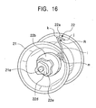
- a side of the slack eliminating roller 21 which has the yarn threading member 22 is defined as a leading end P and its side connected to the driving means 35 is defined as a proximal end Q. Then, the slack eliminating roller 21 is connected to a driving shaft 35a of the driving means 35 using a screw screwed through the outer peripheral surface 21a. Tapered portions 21b, 21d are formed on the proximal end Q side and leading end P side, respectively, of the outer peripheral surface 21a so that their diameters increase toward the corresponding end surfaces.
- An intermediate portion of the slack eliminating roller 21 is a cylindrical portion 21c having a fixed diameter.
- the yarn Y spun by the spinning device 5 is wound around the outer peripheral surface 21a from the proximal end Q side.
- the yarn Y is then unwound from the leading end P to the winding device 12 (see Figures 9 to 11).
- the tapered portion 21b on the proximal end Q side has a function of regularly winding the yarn Y around a surface of the cylindrical portion 21c by smoothly moving the supplied and wound yarn Y from a larger diameter portion 21b-1 to a smaller diameter portion 21b-2 and then to the intermediate cylindrical portion 21c.
- the tapered portion 21d on the leading end P side also has a function of ensuring the smooth pull-out of the yarn Y by inhibiting a slip-out phenomenon in which the wound yarn Y slips out at a time, while sequentially winding the yarn Y around a small diameter portion 21d-2 and then a larger diameter portion 21d-1.
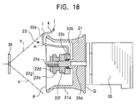
- the yarn threading member 22 is provided on the leading end P side of the slack eliminating roller 21 and a bar-like member 22a is attached to the slack eliminating roller 21, so as to be concentrically rotated by a transmitted force adjusting mechanism relative to the slack eliminating roller 21.
- the transmitted force adjusting mechanism is configured as follows.
- a wheel member 22b is rotatably installed, via a bearing member 22c such as a bearing, on a shaft portion 21e projected from a central portion of the slack eliminating roller 21.
- the proximal portion of the bar-like member 22a is attached to the wheel member 22b.
- the wheel member 22b is attached by preventing a transmitted force applying member 22f composed of urging means such as a spring from slipping out, using a transmitted force adjustment operating section 22g screwed over a bolt portion at the leading end of the shaft portion 21e and composed of, for example, a nut member 22d, a presser member 22e, and the like.
- the transmitted force adjusting mechanism can adjust the pressing force (frictional force) of the transmitted force applying mechanism 22f in a non-step-by-step manner by tightening the transmitted force adjustment operating section 22g screwed over the shaft portion 21e.
- the transmitted force adjusting mechanism can adjust the magnitude of the rotational resistance of the bar-like member 22a to the slack eliminating roller 21.
- the pressing force of the transmitted force applying member 22f, exerted on the wheel member 22b is reduced by loosening the presser member 22e. Accordingly, only a light load enables the bar-like member 22a to rotate independently of the slack eliminating roller 21.
- the pressing force of the spring 22f, exerted on the wheel member 22b is increased by tightening the presser member 22e. Accordingly, the bar-like member 22b rotates integrally with the slack eliminating roller 21 unless a very heavy load acts on it.
- the yarn threading member 22 according to the present embodiment can be set, by appropriately adjusting the tightening of the presser member 22e, to rotate integrally with the slack eliminating roller 21 when the load on the bar-like member 22a has a specified value or smaller and to rotate independently of the slack eliminating roller 21 when the load on the bar-like member 22a exceeds the specified value.
- the bar-like member 22a engages with the yarn Y (see Figures 7 and 8) to allow the yarn Y to be reliably wound around the outer peripheral surface 21a of the slack eliminating roller 21.
- the bar-like member 22a thus has a characteristic shape described below.
- the bar-like member 22a first rises from its proximal end to a position where it projects slightly forward beyond the leading end P of the slack eliminating roller 21.
- the bar-like member 22a then bends at a bent portion n near the axis of the roller 21 so as to extend in a radial direction, and then bends at three portions (m), (l) and (k) located in this order from the inside to outside of the roller.
- a leading end portion (j) of the bar-like member 22a is located outside the radius of the slack eliminating roller 21.
- the two bent portions (k) and (l) lie outside the radius of the slack eliminating roller 21, while the one bent portion (m) is located inside the radius of the slack eliminating roller 21.
- the bar-like member 22a bends at the inward bent portion (m) so as to extend in a direction opposite to the rotating direction of the slack eliminating roller 21.
- the bar-like member 22a then bands at the next bent portion (l) toward the proximal end Q side of the slack eliminating roller 21 and finally at the outer bent portion (k) so as to extend in the rotating direction of the slack eliminating roller 21.
- the bar-like member 22a has a yarn engaging portion R formed of the leading end portion (j), the bent portion (k), and the bent portion (l) and having an angle that opens toward the rotating direction of the slack eliminating roller 21.
- the yarn engaging section R is located above the outer peripheral surface 21a of the slack eliminating roller 21 between the leading end P and proximal end Q of the slack eliminating roller 21.
- the bar-like member 22a rotates with the slack eliminating roller 21 to enable the yarn Y engaged with the bar-like member 22a during slack elimination to be stably wound around the outer peripheral surface 21a of the slack eliminating roller 21 at a predetermined position.
- the bar-like member 22a also prevents the yarn Y from fitting into the gap between the slack eliminating roller 21 and the bar-like member 22a.
- the upstream side guide 23, driven forward and backward by the advance and withdraw driving means 24 such as an air cylinder, is set as follows.
- the upstream side guide 23 holds the yarn path at a position where the yarn Y does not engage with the yarn slack eliminating device 10.
- the upstream side guide 23 moves the yarn path to a position where the yarn Y engages with the bar-like member 22a of the yarn slack eliminating device 10 and is wound around the slack eliminating roller 21.
- the upstream side guide 23 of the the yarn slack eliminating device 10 holds the yarn path at a position where the yarn Y does not engage with the yarn slack eliminating device 10 at the forward position during the normal spinning.
- Each spinning unit 2 of the spinning machine 1 uses the draft device 4 to feed the bundle of fibers S into the spinning device 5.
- the spinning unit 2 uses the yarn feeding device 6 to feed downstream the yarn Y spun and generated by the spinning device 5.
- the spinning unit 2 then passes the yarn Y directly in front of the suction device 7 and the yarn defect detector 9. Subsequently, the spinning unit 2 feeds the yarn Y to the winding device 12 via the upstream side guide 23, the downstream side guide 36, and the waxing device 11.
- the winding device 12 then winds the yarn Y around the bobbin 15 to form the package 16.
- the cutter 8 of the winding unit 2 cuts the yarn Y.
- the back roller 4a and third roller 4b of the draft device 4 stop rotations.
- the cradle arm 14 moves rotatively to separate the package 16 from the rotating drum 13 (see Figure 6). Subsequently, the package 16 naturally stops rotation or is forced to stop depending on the situation.
- the second roller 4d and the front roller 4e continue to be rotatively driven.
- a winding device 12 side part Y2 of the yarn Y cut by the cutter 8 is wound around the package 16, which is continuously rotated by inertia.
- the back roller 4a and third roller 4b of the draft device 4 stop rotations to pull and cut the bundle of fibers S between the stopped third roller 4b and the continuously rotating second roller 4d.
- a yarn piece extending from the cut position to the position of the cutter 8 is fed by the continuously rotating second roller 4d and front roller 4e. The yarn piece passes through the spinning device 5 and is then sucked and removed by the yarn sucking device 7.
- the work carriage 3 runs and moves to the position of the spinning unit 3 that requires splicing. Once the work carriage 3 arrives at a predetermined position, an arrival detection signal is outputted. Then, on the basis of this signal, the spinning unit 2 starts rotating the slack eliminating roller 21 of the yarn slack eliminating device 10 at an appropriate time.
- the work carriage 3 performs the following splicing operation.
- the suction pipe 18 is rotatively moved upward to position the suction port 18a near the yarn discharge port in the spinning device 5. Consequently, the spinning unit 2 reactivates the stopped back roller 4a and third roller 4b to bring them into a driven state.
- the bundle of fibers S is thus fed into the spinning device 5 to restart spinning.
- the suction pipe 18 sucks and catches the yarn end of the yarn Y1 continuously spun by the spinning device 5.
- the suction pipe 18 then moves downward to its initial position shown by the solid line in Figure 6 to guide the yarn Y1 to the yarn splicing device 17.
- the suction port 7a in the yarn sucking device 7 is closed.
- the yarn Y1 is introduced into the yarn feeding device 6 from a side of the nip roller 6a using a separately provided yarn handling means or the like.
- the suction pipe 18 continuously sucks the yarn Y1 generated and fed by the spinning device 5 until a subsequent yarn splicing operation is started.
- the suction mouth 19 is rotatively moved downward to the position shown by the alternate long and two short dashes line in Figure 6. Then, the suction port 19a at the tip of the suction mouth 19 is used to suck and catch the yarn end of the yarn Y2 from the package 16 having stopped rotating. The yarn Y2 is thus pulled out. Then, while continuing the suction, the suction mouth 19 is rotatively moved upward to its initial position shown by the solid line in Figure 6. The winding device 12 side yarn Y2 is thus positioned near the yarn splicing device 17.
- the yarn splicing device 17 starts a yarn splicing operation.
- a yarn handling lever (not shown in the drawings) provided in the yarn splicing device 17 clamps and loads both yarns Y1, Y2 into a work executing section of the yarn splicing device 17.
- a yarn splicing operation is then performed. Before the yarn splicing operation is started, the upstream side guide 23 of the yarn slack eliminating device 10 is still at the forward position to hold the yarn path at a position where it does not engage with the yarn threading member 22.
- the suction pipe 18 can no longer suck or collect the yarn Y1. Accordingly, the yarn Y1, fed by the spinning device 5, is collected upstream of the yarn splicing device 17 if no action is taken.
- the advance and withdraw driving means 24 is activated to withdraw the upstream side guide 23 as shown in Figures 7 and 8.
- the yarn Y1 changes its yarn path so as to engage with the bar-like member 22a of the yarn threading member 22. Operation signals for the advance and withdraw driving means 24 are outputted by the control means of the work carriage 3 using appropriate timing.
- the upstream side guide 23 itself functions as yarn moving means for moving the yarn Y1 from a yarn path (on which the yarn can engage with the bar-like member 22a) joining the upstream side guide 23, which lies at the backward position, and downstream side guide 36 together so as to establish the shortest distance between them, to a yarn path on which the yarn does not engage with the bar-like member 22a.
- the upstream side guide 23 may be fixed, while separate yarn moving means may be provided.
- the bar-like member 22a can be rotated independently of the slack eliminating roller 21. However, it rotates integrally with the slack eliminating roller 21 unless a load of a specified value or larger acts on the bar-like member 22a. During the yarn slack eliminating operation, yarn tension is weak and only a light load acts on the bar-like member 22a. The bar-like member 22a thus rotates integrally with the slack eliminating roller 21.
- the bar-like member 22a Since the bar-like member 22a is formed as described previously, it is ensured to engage with the yarn Y. Furthermore, the yarn Y does not fit into the gap between the slack eliminating roller 21 and the bar-like member 22a during winding. Moreover, the withdrawal of the upstream side guide 23 is an operation preformed in a direction in which the length of the yarn path is reduced to relax the yarn tension. Accordingly, an increase in yarn tension is reduced when the yarn Y1 engages with the bar-like member 22a. This prevents yarn breakage.
- the rotation speed of the slack eliminating roller 21 is set so as to provide an appropriate yarn tension, on the basis of a speed at which the spinning device 5 spins the yarn Y (substantially a speed at which the yarn feeding device 6 feeds the yarn).
- the time when the upstream side guide 23 moves is determined taking the spinning speed of the yarn Y1 into account. Using as a reference the time when the yarn splicing device 17 clamps the yarns Y1, Y2, the above time is set, for example, to be slightly before this clamp time. When this movement occurs before the set time, the yarn Y1, successively spun by the spinning device 5, may be slacked. The slack eliminating roller 21 may then fail to catch the yarn Y1.
- the yarn Y1 positioned in the yarn splicing device 17 may be wound around the slack eliminating roller 21, resulting in an incomplete yarn splicing operation.
- the cradle arm 14 is rotatively moved to contact the package 16 with the rotating drum 13. Then, the operation of winding the yarn Y is restarted. However, the yarn Y undergoes a reduced tension immediately after the yarn splicing has been completed. Accordingly, when the package 16 is rapidly brought into contact with the rotating drum 13, the yarn tension may vary rapidly to excessively tense and break the yarn Y.
- the present embodiment provides a tension arm 20 which tenses the yarn Y and which can advance and withdraw and a speed limiting mechanism 26 that adjusts the rotative movement speed of the cradle arm 14, as shown in Figure 12.
- the tension arm 20 is a lever structure such as the illustrated one.
- the tension arm 20 presses the yarn Y to increase its tension immediately before the contact of the package 16 with the rotating drum 13 is completed.
- the speed limiting mechanism 26 is constructed utilizing a cam 26a, a link 26b, and the like.
- the speed limiting mechanism 26 is connected to a junction 26c provided in the cradle arm 14 to limit the rotative movement speed of the cradle arm 14 immediately before the package 16 comes into contact with the rotating drum 13.
- the tension arm 20 and the speed limiting mechanism 26 operate as shown in, for example, the time chart in Figure 13.
- the cradle arm 14 first starts moving rotatively.
- the speed limiting mechanism 26 controls the cradle arm 14 so that its rotative movement speed (angular speed) does not exceed a predetermined value.
- angular speed angular speed
- the angular speed of the cradle arm 14 is reduced to a specified value.
- This low angular speed is maintained.
- This angular speed control allows the package 16 to come into sliding contact with the surface of the rotating drum 13. This relaxes a shock upon contact.
- the tension arm 20 is advanced after the cradle arm 14 has started the sliding contact and before the contact is completed.
- the yarn Y is thus tensed.
- the yarn Y undergoes a reduced tension immediately after the yarn splicing has been finished.
- the package 16 contacts completely with the rotating drum 13 to restart a regular winding operation.
- the yarn tension then increases rapidly.
- the yarn tension is slightly increased before the package 16 finishes contacting with the rotating drum 13, that is, before the yarn tension increases rapidly.
- a variation in yarn tension can be reduced when a regular winding operation is restarted, thus preventing the yarn from being excessively tensed and broken.
- the tension arm 20 is immediately withdrawn and separated from the yarn Y. This avoids affecting yarn quality and applying an extra tension.
- the work carriage 3 no longer engages with the yarn Y and can move freely from the spinning unit 2 on which the spinning operation has been performed. Accordingly, when another spinning unit outputs a yarn splicing request signal, the work carriage 3 can move immediately to the position of the target spinning unit after the winding operation has been restarted, without waiting for the yarn to be unwound from the slack eliminating roller 21. Consequently, the spinning machine 1 according to the present invention saves the time required by the work carriage 3 to remain at a single spinning unit 2. This enables consecutive yarn splicing operations to be finished within a time shorter than that required in the prior art.
- the yarn Y generated and fed by the spinning device 5 is wound around the continuously rotating slack eliminating roller 21.
- the yarn tension increases above a specified value because the ratio of the winding speed to the spinning speed is set so as to apply an appropriate tension to the yarn.
- a load of a value larger than the one set by the transmitted force adjusting mechanism acts on the bar-like member 22a.
- the bar-like member 22a starts rotating independently of the slack eliminating roller 21, which is continuously rotating in the winding direction.
- the yarn wound and retained around the slack eliminating roller 21 is thus gradually unwound from the slack eliminating roller 21.
- the bar-like member 22a of the yarn threading member 22 executes a function to guide the yarn Y so that it is uniformly unwound from the slack eliminating roller 21, while preventing the yarn Y from slipping out.
- the bar-like member 22a also executes a function to contact with the yarn Y to allow it to offer an appropriate resistance to set a proper yarn tension, thus making the winding of the package 16 uniform.
- the yarn threading member 22 is a single member having two functions. That is, the yarn threading member 22 provides a yarn guiding function to introduce the yarn Y1 into the slack eliminating roller 21 immediately before the start of a yarn splicing operation.
- the yarn threading member 22 also provides an unwinding tension applying function to apply a predetermined unwinding tension to the yarn woun. around the slack eliminating roller 21 when this yarn is unwound. This effectively reduces the number of parts constituting the yarn slack eliminating device 10.
- the slack eliminating roller 21 is reversely rotated through almost 180 degrees to a position where the bar-like member 22a does not contact with the yarn Y, as shown in Figures 15C and 15D. Subsequently, the slack eliminating roller 21 is stopped. This makes it possible to avoid degrading the yarn Y. After the slack eliminating roller 21 has been reversely rotated and then stopped, the upstream side guide 23 is advanced to return to its initial position shown in Figures 3 and 4.
- timer control can be used to adjust timing for reversely rotating the slack eliminating roller 21.
- the slack eliminating roller 21 may be set to be automatically reversely rotated and then stopped after the slack eliminating roller 21 has rotated for a predetermined time since the start of the yarn slack eliminating operation in the yarn slack eliminating device 10.
- a tension sensor may be arranged at an appropriate position located upstream or downstream of the slack eliminating roller 21 to monitor the tension of the yarn being unwound. Then, once the tension value meets a specified condition, the slack eliminating roller 21 may be reversely rotated and then stopped.
- the cutter 8 and the yarn defect detector 9 are arranged upstream of the yarn slack eliminating device 10 and close to each other. The reason will be described below.
- the cutter 8 When the cutter 8 is located downstream of the yarn slack eliminating device 10, if the yarn defect detector 9 detects a defect while the slack eliminating roller 21 is eliminating the slack, then the upstream yarn end cut by the cutter 8 remains wound around the slack eliminating roller 21. To remove this yarn end, a complicated arrangement and complicated control are required. That is, removal means separately provided downstream of the cutter 8 must be used discard the remaining yarn end while the slack eliminating roller 21 is being reversely rotated.
- the cutter 8 is located upstream of the yarn slack eliminating device 10, whereas the yarn defect detector 9 is arranged downstream of the yarn slack eliminating device 10.
- the cutter 8 cuts the yarn Y.
- the length of the yarn Y between the yarn end cut by the cutter 8 and the yarn defect portion detected by the yarn defect detector 9 increases by an amount equal to the length of the yarn Y wound around the slack eliminating roller 21. Consequently, a large amount of yarn Y may be discarded or a long time may be required for suction.
- the suction mouth 19 may not be able to suck or catch the yarn defect portion and thus the yarn defect portion may fail to be removed before yarn splicing.
- the yarn defect portion may be wound into the package 16. Therefore, for the above described reason, the cutter 8 and the yarn defect detector 9 are preferably arranged upstream of the yarn slack eliminating device 10 and close to each other.
- the upstream side guide 23 is advanced immediately before yarn slack elimination carried out by the slack eliminating roller 21 partly because the yarn Y must be removed from the yarn defect detector 9 while the yarn path of the yarn Y is at an unengaged position immediately before the stack elimination.
- the upstream side guide 23 of the slack eliminating roller 21 may be fixed, whereas the downstream side guide 36 may be movable, as shown in Figure 19.
- the upstream side guide 23 is closer to the yarn defect detector 9 than the downstream side guide 36, if the condition that the yarn Y is removed from the yarn defect detector 9 immediately before slack elimination is met, the upstream side guide 23 is preferably advanced to bend the yarn Y in removing the yarn from the yarn defect detector 9. This operation reduces a movement stroke and can prevent the member from projecting excessively compared to the case in which the downstream side guide 36 is advanced and withdrawn.
- the embodiments of the present invention are not limited to the above described aspects.
- the present invention is applied to a spinning machine having a plurality of spinning units.
- the present invention is applicable to a single spindle type spinning machine.
- the yarn splicing device 17 is mounted on the work carriage 3 and this single yarn splicing device 17 performs yarn splicing operations on all the spinning units 2.
- an arrangement may be employed in which the yarn splicing device 17 is provided for each spinning unit 2.
- the work carriage 3 can be omitted.
- the yarn slack eliminating device 10 may be mounted on the work carriage 3 so that this single yarn slack eliminating device 10 can perform yarn slack eliminating operations on all the spinning units.
- the present invention is applied to the spinning machine designed so that during normal winding, the yarn Y is not wound around the slack eliminating roller 21.
- the present invention may be utilized to construct a spinning machine adapted to adjust the winding speed to slack the yarn even during normal winding so that the yarn Y is always wound around the slack eliminating roller 21.
- the present invention is applicable to, for example, the case in which cone packages are formed and in which the yarn Y is always wound around the slack eliminating roller 21 in order to absorb a difference in winding tension resulting from a difference in winding speed between the larger diameter side and smaller diameter side of the package.
- the specific configuration or shape of the present invention may be properly changed in accordance with the situation.
- a spinning machine is known in which if yarn breakage occurs in one of the spinning units constituting the spinning machine, a yarn splicing operation is performed by the yarn splicing device disposed in the spinning unit or disposed on the work carriage running along the spinning machine as described in the above embodiments.
- a spinning machine provided with a spinning device as described above is disclosed in, for example, the Unexamined Japanese Patent Application Publication No. 2001-40532.
- the above spinning machine does not have any means for sensing whether or not the suction mouth has sucked and caught the yarn end wound around the package. Accordingly, even if the suction mouth fails to suck and catch the lower yarn, a bundle of fibers is still supplied to the spinning device. Then, the generated yarn is sucked and removed by the suction pipe. As a result, the bundle of fibers may be wasted.
- a fourth embodiment of the present invention solves the above described problem of the spinning machine equipped with the conventional yarn splicing device.
- S1 is a lower-yarn detecting member disposed on the work carriage 3.
- the lower-yarn detecting member S1 is arranged so as to stand near the lower yarn Y2 extending from the package 16 to the suction mouth 19 when the suction mouth 19 returns to a standby position, shown by a solid line in Figure 21, after sucking and catching the lower yarn Y2 wound into the package 16, as described above.
- the lower-yarn detecting member S1 can be configured as a reflection type photoelectric sensor s1 that does not contact with the lower yarn Y2; that is, this sensor S1 is of a non-contact type.
- a reverse rotating roller 120 causes the suction mouth 19 to rotatively move downward from the standby position, shown by the solid line in Figure 21, to approach the package 16 as shown by the alternate long and two short dashes line in the figure, the package 16 being rotated in a direction opposite to the normal winding direction.
- the suction mouth 19 thus sucks and catches the lower yarn Y2 wound into the package 16. Subsequently, the suction mouth 19 returns to the standby position, shown by the solid line in the figure. Then, the lower yarn Y2 sucked and caught by the suction mouth 19 is unwound from the package 16. During the unwinding, the yarn Y is wound while being traversed by a traverse device T.
- the photoelectric sensor s1 transmits a lower-yarn detection pulse to a control section disposed on the work carriage 3 and described later.
- the lower-yarn detecting member S1 detects the lower yarn Y2 being traversed. Accordingly, the lower-yarn detecting member S1 is preferably arranged above an axial and substantially central portion of the package 16 (in a direction in which the lower yarn 2 is unwound).
- the lower yarn Y2 is traversed and ensured to cross the photoelectric sensor s1. Accordingly, by detecting about one or two pulses, the lower-yarn detecting member S1 can determine and detect that the yarn end caught in the package 16 has been pulled out.
- the lower-yarn detecting member S2 shown in Figure 23 is configured as a detecting guide member s2 disposed on the work carriage 3 and having a yarn groove s2a.
- the suction mouth 19 sucks and catches the lower yarn Y2 wound around the package 16 and then returns to the standby position, shown by the solid line in Figure 21, the lower yarn Y2 is inserted into the yarn groove s2a.
- a photoelectric sensor s2b or the like (not shown in the drawings) disposed near the yarn groove s2a detects the lower yarn Y2 sucked by the suction mouth 19.
- the position where the yarn contacts with the lower-yarn detecting member S2 varies depending on the positions of the yarn Y being traversed and the lower-yarn detecting member S2. This may vary the tension of the lower yarn Y2.
- the lower-yarn detecting member S2 is preferably of a non-contact type similarly to the lower-yarn detecting member S1.
- a lower-yarn detecting member such as a photoelectric sensor may be provided in the suction mouth 19.
- the lower yarn Y2 sucked and caught by the suction mouth 19 may be caught in the lower-yarn detecting member.
- the non-contact type lower-yarn detecting member S1 is preferably used which detects the traverse of the lower yarn S2 being unwound and which does not contact with the lower yarn Y2 sucked and caught in the suction mouth 19.
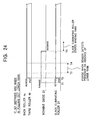
- Figure 24 shows a driving stop timing for the back roller 4a and third roller 4b, a forward and backward timings for the movable (upstream side) guide 23, and a rotation stop timing for the slack eliminating roller 21 used if the suction mouth 19 does not make any mistakes in sucking or catching the lower yarn Y2, resulting in successful yarn splicing, as described above.
- the movable guide 23 is advanced (time T1).
- the slack eliminating roller 21 starts rotating (time T2) simultaneously with the restart of driving of the back roller 4a and third roller 4b.
- the lower-yarn detecting member S1 keeps detecting that the suction mouth 19 is sucking and catching the lower yarn Y2, for a predetermined time after the restart of driving of the back roller 4a and third roller 4b (times T3 ⁇ T4). Subsequently, the movable guide 23 is withdrawn (time T5).
- the machine can be configured so that the slack eliminating roller 21 is stopped if the yarn Y is completely unwound from the slack eliminating roller 21.
- the suction mouth 19 is rotatively moved downward from the standby position, shown by the solid line in Figure 12, to the position shown by the alternate long and two short dashes line. Then, the reverse rotating roller 120 is used to allow the suction port 19a in the suction mouth 19 to near the package 16 rotating in the direction opposite to the normal winding direction. Then, an operation of sucking and catching the lower yarn Y2 wound into the package 16 is performed for a predetermined time. However, when the suction mouth 19 is returned to the upper standby position, if the lower yarn Y2 has not sucked or caught in the suction mouth 19, the lower-yarn detecting member S2 does not output any lower-yarn detection pulses during times T3 and T4.
- the control section C1 disposed on the work carriage 3 gives an instruction to immediately stop driving the back roller 4a and the third roller 4b via a calculating section C2 (see Figure 26) and the driver substrate 30 (time T4).
- the lower-yarn detecting member S2 detects that the lower yarn Y2 has not been sucked or caught by the suction mouth 19
- the driving of the back roller 4a and the third roller 4b is immediately stopped. This makes it possible to prevent the bundle of fibers S from being wasted.
- the bundle of fibers S supplied between times t2 and t4 is formed by the spinning device 5 into the yarn Y, sucked by the suction pipe 18, and then discarded. Then, until the yarn end of the upper yarn Y1 formed by stopping driving the back roller 4a and the third roller 4b to cut the bundle of fibers S passes above the movable guide 23 (time T6), the control section C1 holds the movable guide 23 at its advanced position. The control section C1 also provides such control as prevents the upper yarn Y1 from engaging the bar-like member 22a.
- timer means for counting the elapse of a predetermined time from the time T4, when the supply of the bundle of fibers S is stopped, or detecting means for detecting that the yarn end of the upper yarn Y1 has passed through the movable guide 23.
- Figure 26 illustrates a control block as an example.
- the result of detection of the lower yarn Y2 executed by the lower-yarn detecting member S1 is transmitted to the control section C1 of the work carriage 3.
- instructions from the control section C1 of the work carriage 3 drive or stop the driving of the advance and withdraw driving means 24, composed of an air cylinder or the like, and move the movable guide 23 forward and backward, which is disposed in the spinning unit 2.
- the advance and withdraw driving means 24 is composed of an air cylinder, and an instruction from the control section C1 controls a solenoid valve V that supplies or interrupts the supply of compressed air from a compressed air source to the advance and withdraw driving means 24.
- C3 is a yarn splicing operation re-instructing section for instructing on a yarn splicing operation again on the basis of the detection of a mistake in the pull-out of the lower yarn Y2, carried out by the yarn splicing device 17. Even if the suction mouth 19 makes a mistake in sucking and catching the lower yarn Y2, the upper yarn Y1 spun by the splicing device 5 is not wound around the slack eliminating roller 21 because the movable guide is at its advanced position. Consequently, even if a mistake is made in pulling out the lower yarn Y2, the yarn splicing operation can be performed again.
- each spinning unit 2 is provided with the members installed on the work carriage 3 and required for a yarn splicing operation, for example, the yarn splicing device 17, the suction pipe 18, the suction mouth 19, and the advance and withdraw driving means 24.
- a yarn winder comprises guide members arranged on an upstream and downstream sides, respectively, of the slack eliminating roller, a yarn threading member arrange at a position where the yarn threading member can be engage with a yarn on the shortest yarn path between the upstream side guide and the downstream side guide, and yarn moving means for moving the yarn from the shortest yarn path to a yarn path on which the yarn does not engage with the yarn threading member. Consequently, if a yarn splicing operation is to be performed, then before the start of the operation, the yarn moving means holds the yarn away from the yarn path corresponding to the shortest distance and at a position at which the yarn does not engage with the yarn threading member.
- the yarn is moved to the position of the yarn path corresponding to the shortest distance and is then engaged with the yarn threading member. Accordingly, the direction of the operation of engaging the yarn with the yarn threading member does not involve an increase in yarn tension. Therefore, the yarn can be reliably prevented from being excessively tensed and broken.
- the yarn winder according to the present invention is adapted as set forth in Claim 3. That is, a yarn detect detector and a cutter are provided upstream of the slack eliminating roller, and the movable upstream side guide provided upstream of the slack eliminating roller is moved to enable the yarn to be moved between the position where the yarn can engage with the yarn threading member and the position where the yarn does not engage with the yarn threading member, so that the yarn is placed away from the yarn defect detector when the yarn path is not engaged with the yarn threading member. Then, after the yarn has been cut, a part of the yarn remaining on the slack eliminating roller can be easily processed. Consequently, many advantages are obtained.
- the yarn winder is provided with a detecting member that detects whether or not the yarn end wound around a package has been pulled out by a winding side yarn end catching member and control means for controlling a supply of a bundle of fibers on the basis of the detection result from the detecting member so that the supply of the bundle of fibers is stopped when the yarn end fails to be pulled out of the package. Consequently, the bundle of fibers can be prevented from being wasted. It is also possible to quickly and reliably retain a large amount of yarn supplied during a yarn splicing operation without the need to increase the length of a yarn sucking device or to increase the yarn suction force of the yarn sucking device as in the case of conventional yarn winders (spinning machines). Furthermore, even if a mistake is made in withdrawing the winding side yarn end, the yarn can be prevented from being wound around the slack eliminating roller 21 to eliminate the need for the operator's removing operation.
- the detecting member is of a non-contact type that does not contact with a yarn. This prevents the yarn from being degraded by its contact with the detecting member.
Abstract
Description
- The present invention relates to a yarn winder comprising a yarn slack eliminating device that eliminates the slack of a yarn that may occur between a supply side and a winding device during a yarn splicing operation.
- With a fast spinning machine such as a pneumatic spinning machine, if a yarn defect is detected, the yarn defect portion is cut and removed using a cutter. Then, a yarn splicing device splices the leading end of a yarn successively fed by a spinning device, to a yarn end on a package. The yarn splicing operation is performed while winding of the yarn remains stopped. Accordingly, to eliminate the slack of the yarn successively fed by the spinning device, means has hitherto been employed which sucks the excessive part of the yarn using a suction tube called a slack tube as described in the Unexamined Japanese Patent Application Publication (Tokkai-Hei) No. 2001-159039.
- However, as the amount of yarn slack increases consistently with spinning speed, it becomes more and more difficult to deal with an increased amount of yarn slack using the above described suction tube system. Thus, as an alternative to the suction tube system, the Examined Japanese Patent Application Publication (Tokkou-Hei) No. 4-13272 describes a roller type yarn storage device (yarn slack eliminating device) which eliminates yarn slack by temporarily winding a yarn fed by a spinning device around a storage roller (slack eliminating roller). The yarn storage device is loaded, together with a yarn binding device (yarn splicing device), on a maintenance device (work carriage) that can run along a spinning machine. Furthermore, the yarn storage device is provided with a return element composed of a yarn return ring, in addition to the storage roller. The return element has a function of guiding the introduction of a yarn when it is wound around the storage roller during yarn splicing, and guiding the unwinding of the yarn when the yarn is unwound from the storage roller after the winding has been restarted.
- The technique in the Examined Japanese Patent Application Publication (Tokkou-Hei) No. 4-13272 is set so that when during a yarn splicing operation, the yarn is wound around the storage roller in order to eliminate the yarn slack, the yarn guide pulls and engages the yarn with the return element. On this occasion, yarn tension never fails to increase. Accordingly, an excessive yarn tension may be applied between a yarn guide and the yarn binding device depending on timing used to allow the yarn binding device to clamp the yarn. Consequently, the yarn may be excessively tensed and broken.
- A yarn winder according to
Claim 1 of the present invention is employed in order to solve the above conventional problems. That is, according toClaim 1, there is provided a yarn winder comprising a yarn slack eliminating device, the yarn winder being characterized in that the yarn slack eliminating device has a slack eliminating roller, guide members arranged on an upstream and downstream sides, respectively, of the slack eliminating roller, and a yarn threading member, and the yarn threading member is arranged at a position where the yarn threading member can be engage with a yarn on the shortest yarn path between the upstream side guide and the downstream side guide, and the yarn slack eliminating device comprises yarn moving means for moving the yarn from the shortest yarn path to a yarn path on which the yarn does not engage with the yarn threading member. - The yarn winder according to the present invention configured as described above can perform a yarn splicing operation as described below. Before a yarn splicing operation is started, the yarn moving means holds the yarn on the yarn path on which it engages with the yarn threading member. Immediately before yarn splicing is executed, the yarn moving means moves the yarn to the shortest yarn path between the upstream side guide and the downstream side guide. The yarn is thus engaged with the yarn threading member placed at the position where the yarn threading member can engage with the shortest yarn path. The yarn is then wound around the slack eliminating roller.
- Specifically, the yarn winder according to the present invention moves the yarn lying at the position where it does not engage with the yarn threading member positioned away from the yarn path corresponding to the shortest distance, to the position where it matches the yarn path corresponding to the shortest distance, to engages the yarn with the yarn guiding device. Accordingly, the direction of an operation of engaging the yarn with the yarn threading member does not involve an increase in yarn tension caused by the marked bending of the yarn during yarn guiding.
- If a plurality of winding units are disposed in the yarn winder and are each provided with the yarn slack eliminating device, the arrangement set forth in
Claim 2 can be employed. That is, driving means for the yarn moving means or control means for the driving means is provided on a work carriage on which a yarn splicing device is mounted and which can move among the winding units. This arrangement makes it possible to easily control the yarn splicing operation performed by a work carriage and the operation of the yarn slack eliminating using approximate timings. - Moreover, as set forth in
Claim 3, the yarn winder according to the present invention may be set so that a yarn detect detector and a cutter are provided upstream of the slack eliminating roller, the cutter cutting a yarn on the basis of a detection result from the yarn detect detector, and the movable upstream side guide provided upstream of the slack eliminating roller is moved to enable the yarn to be moved between the position where the yarn can engage with the yarn threading member and the position where the yarn does not engage with the yarn threading member, so that the yarn is placed away from the yarn defect detector when the yarn path is not engaged with the yarn threading member. - If the yarn detect detector and the cutter cutting a yarn on the basis of a detection result from the yarn detect detector are provided upstream of the slack eliminating roller as described previously, then first, after the cutting of the yarn using the cutter, a part of the yarn which remains wound around the slack eliminating roller can be easily processed. Second, during a defect portion removing and yarn splicing operations following the detection of a defect by the yarn defect detector, it is advantageously possible to prevent errors such as a large amount of discarded yarn or winding of a yarn defect portion around a winding package. Furthermore, by setting the yarn winder so that the yarn is separated from the yarn defect detector when the yarn is in an unengaged position, it is possible to prevent shaking of the yarn which may occur upon engagement of the yarn with the yarn threading member from being detected as the occurrence of a yarn defect. Moreover, making the upstream side guide movable enables a reduction in the movement stroke of the yarn moving means.
- According to
Claim 4, the yarn winder comprises a winding device that winds a supplied yarn into a package, a splicing device that splices a supply side yarn end to a winding side yarn end, and a winding side yarn end catching member that pulls out and catches the winding side yarn end from the package. Furthermore, the yarn winder is provided with a detecting member that detects whether or not the yarn end wound around a package has been pulled out by the winding side yarn end catching member, control means for controlling a supply of a bundle of fibers on the basis of the detection result from the detecting member, and control means for controlling winding of the yarn around the slack eliminating roller on the basis of the detection result from the detecting member. According toClaim 5, the winding device comprises a traverse device that traverses a supplied yarn, and the detecting member detects traverse of the winding side yarn caught by the winding side yarn end catching member and unwound from a package. The yarn winder according toClaim 6 is characterized in that the detecting member is of a non-contact type that does not contact with a yarn. -
- Figure 1 is a front view showing a first embodiment of a spinning machine comprising a yarn slack eliminating device according to the present invention.
- Figure 2 is a front sectional view schematically showing the structure of essential parts of the first embodiment.
- Figure 3 is a side view schematically showing the configuration of a spinning unit and a work carriage during normal winding according to the first embodiment.
- Figure 4 is an enlarged side view of the yarn slack eliminating device section during normal winding according to the first embodiment.
- Figure 5 is an enlarged front view of the yarn slack eliminating device section during normal winding according to the first embodiment.
- Figure 6 is a side view schematically showing the configuration of the spinning unit and the work carriage immediately before the start of a yarn splicing operation according to the first embodiment.
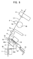
- Figure 7 is a side view schematically showing the configuration of the spinning unit and the work carriage upon the start of the yarn splicing operation according to the first embodiment.
- Figure 8 is an enlarged side view schematically showing the configuration of the yarn slack eliminating device section upon the start of the yarn splicing operation according to the first embodiment.
- Figure 9 is a side view schematically showing the configuration of the spinning unit and the work carriage during the yarn splicing operation according to the first embodiment.
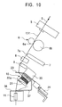
- Figure 10 is an enlarged side view schematically showing the configuration of the yarn slack eliminating device section during the yarn splicing operation according to the first embodiment.
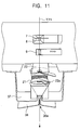
- Figure 11 is an enlarged front view schematically showing the configuration of the yarn slack eliminating device section upon the start of the yarn splicing operation according to the first embodiment.
- Figure 12 is a side view schematically showing the configuration of the yarn slack eliminating device section after the yarn splicing and immediately before the restart of a winding operation according to the first embodiment.
- Figure 13 is a time chart showing operations of a tension arm and a cradle arm performed after the yarn splicing and before the restart of the winding operation according to the first embodiment.
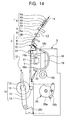
- Figure 14 is a side view schematically showing the configuration of the spinning unit and the work carriage after the restart of the winding according to the first embodiment.
- Figure 15 shows the first embodiment wherein Figure 15A is an enlarged side view schematically showing the configuration of the yarn slack eliminating device immediately after unwinding of the yarn from the roller following the restart of the winding operation, Figure 15B is a front view showing the slack eliminating roller in the same state as viewed from its leading end, Figure 15C is an enlarged side view schematically showing the configuration of the yarn slack eliminating device after reverse rotation of the slack eliminating roller executed after Figures 15A and 15B to avoid engaging with the yarn, and Figure 15D is a front view showing the slack eliminating roller in the same state as viewed from its leading end.
- Figure 16 is a perspective view showing an example of a slack eliminating roller utilized in the yarn slack eliminating device according to the first embodiment as viewed from its leading end.
- Figure 17 shows the example of the slack eliminating roller utilized in the yarn slack eliminating device according to the first embodiment wherein Figure 17A is s front view as viewed from the leading end of the slack eliminating roller and Figure 17B is a plan view.
- Figure 18 is a side sectional view showing the example of the slack eliminating roller utilized in the yarn slack eliminating device according to the first embodiment.
- Figure 19 is an enlarged side view schematically showing a yarn slack eliminating device according to a second embodiment of the present invention.
- Figure 20 is a schematic side view of a spinning unit and a work carriage constituting a spinning machine according to the present invention.
- Figure 21 is a schematic side view of the spinning unit and work carriage constituting the spinning machine according to the present invention.
- Figure 22 is a schematic front view of a lower-yarn detecting member, a suction mouth, and others disposed in the spinning machine according to the present invention.
- Figure 23A is a schematic side view of a lower-yarn detecting member, a suction mouth, and others according to another embodiment, the components being disposed in the spinning machine according to the present invention, and Figure 23B is a plan view of a detecting guide member constituting a lower-yarn detecting member.
- Figure 24 is a chart showing driving timings for a back roller, a movable guide, and a slack eliminating roller constituting the spinning machine according to the present invention.
- Figure 25 is a chart similar to Figure 24 and showing driving timings for the back roller, movable guide, and slack eliminating roller constituting the spinning machine according to the present invention.
- Figure 26 is a schematic side view of the spinning unit and work carriage constituting the spinning unit according to the present invention, showing a control block.
-
- With reference to the drawings, a description will be given of embodiments of a spinning machine according to the present invention. In the specification, the terms "upstream" and "downstream" are based on a direction in which a yarn runs during spinning. Specifically, the upstream side corresponds to a spinning device, while the downstream side corresponds to a winding device.
- Figure 1 is a front view showing an example of a spinning
machine 1 to which the present invention is applied. Figure 2 is an enlarged view schematically showing the internal structure of a part of the spinningmachine 1. The spinningmachine 1 is composed of, for example, a pneumatic spinning machine. Main constituent members of the spinningmachine 1 include acontrol section 1A, aspinning section 1B in which a large number ofspinning units 2 are arranged in line, ablower section 1C, and awork carriage 3 comprising a yarn splicing device and adapted to run freely along a rail R between the spinningunits 2. - The
control section 1A controls the operations of drivingmotors shafts spinning units 2 constituting thespinning section 1B, the operations ofmotors spinning unit 2, the operation of a windingdevice 12, and the like. In the present embodiment, on the basis of various set values (a spinning speed, the ratio of the spinning speed to a winding roller speed, and the like) inputted to an input section a, a calculating section (b) outputs spinning speed information to themotors 31 ~ 34 via an inverter (c) or adriver substrate 30. Furthermore, rotation speed information on a slack eliminating roller (described later) is outputted to themotor 35 of the yarnslack eliminating device 10 via adriver substrate 40. - The
spinning section 1B is composed of the large number ofspinning units 2 arranged in line. Each of thespinning units 2 is configured to be independently controlled. The spinningmachine 1 according to the present invention is characterized in that in addition to aspinning device 5 and a windingdevice 12, a yarnslack eliminating device 10 is provided for eachspinning unit 2. The structure of thespinning unit 2 will be described later in detail. - The
blower section 1C houses compressed air supplying means for supplying compressed air to a desired portion of the spinning unit through an air duct and negative pressure supplying means for supplying a negative pressure (suction pressure) to a desired position of thespinning unit 2 through an air duct. For example, theblower section 1C supplies compressed air to thespinning device 5 of thespinning unit 2 to allow the negative pressure to act on a sucking device. - On the basis of a yarn splicing request signal, the
work carriage 3 is adapted to run on the rail R to move to the position of aspinning unit 2 requiring yarn splicing and then to stop there. As shown Figure 3 that is a side sectional view schematically illustrating the configuration of thespinning section 1B, thework carriage 3 comprises ayarn splicing device 17 such as a knotter or a splicer, asuction pipe 18 that sucks an end of a yarn formed by thespinning device 5 and guides the end to theyarn splicing device 17, asuction mouth 19 that sucks a yarn end of apackage 16 supported by the windingdevice 12 and guides the yarn end to theyarn splicing device 17, and atension arm 20 that contacts with and tenses a yarn Y as required (see Figure 12). Thework carriage 3, which runs along the direction in which thespinning units 2 are arranged in parallel, is thus provided with theyarn splicing device 17, thesuction pipe 18, and thesuction mouth 19. Accordingly, a yarn splicing operation can be performed on all thespinning units 2 using only the above set of components. This simplifies the structure of the spinningmachine 1. - The
suction pipe 18, provided on thework carriage 3 for yarn splicing, functions as a member that sucks the spinning-side yarn end. Thesuction pipe 18 comprises asuction port 18a at its leading end and can be rotatively moved around a pivotal supportingsection 18b. For a yarn splicing operation, thesuction pipe 18 is rotatively moved upward as shown by the alternate long and two short dashes line in Figure 6 to position thesuction port 18a near a yarn discharge port in thespinning device 5. Then, thesuction pipe 18 sucks the yarn end of the spun yarn Y and is then rotatively moved downward to its initial position shown by the solid line in the same figure while sucking the yarn Y. Thesuction pipe 18 thus guides a spinning side yarn Y1 to theyarn splicing device 17. On the other hand, thesuction mouth 19 functions as a member that sucks a winding side yarn end. Thesuction mouth 19 comprises asuction port 19a at its leading end and can be rotatively moved around a pivotal supportingsection 19b. For a splicing operation, thesuction pipe 18 is rotatively moved downward as shown by the alternate long and two short dashes line in Figure 6. Thesuction pipe 18 then sucks the yarn end from thepackage 16 having stopped rotating, through thesuction port 19a at its leading end to pull out the yarn Y. Then, thesuction pipe 18 is rotatively moved upward to its initial position shown by the solid line in the same figure while sucking the yarn. A yarn Y2 on thepackage 16 side is thus guided to theyarn splicing device 17. - Now, a description will be given of the plurality of spinning
units 2, arranged in thespinning section 1B. As shown in Figure 3, thespinning unit 2 is composed of adraft device 4, thespinning device 5, ayarn feeding device 6, ayarn sucking device 7, acutter 8, ayarn defect detector 9, the yarnslack eliminating device 10, awaxing device 11, and the windingdevice 12. These components are arranged in this order from upstream side to downstream side of a yarn path E. - The
draft device 4 is composed of four lines including, for example, aback roller 4a, athird roller 4b, asecond roller 4d from which anapron 4c is extended, and afront roller 4e, the rollers being arranged in this order from the upstream side. Thespinning device 5 is of, for example, a pneumatic type that utilizes whirling air currents to generate the spun yarn Y (hereinafter simply referred to as the "yarn Y") from the bundle of fibers S. Theyarn feeding device 6 is composed of anip roller 6a and adelivery roller 6b to feed the yarn Y downward while sandwiching it between therollers yarn sucking device 7 always sucks the air, and when theair defect detector 9 detects a defect in the yarn Y, sucks and removes pieces of the yarn Y cut by thecutter 8. The waxingdevice 11, provided downstream of the yarnslack eliminating device 10, is designed to, for example, applies tension using a movable guide roller urged in a direction in which it is separated from a fixed guide roller. These guide rollers are not shown in the drawings. - The winding
device 12 winds the yarn Y around a bobbin held on acradle arm 14 to form thepackage 16. The windingdevice 12 comprises arotating drum 13 that rotates in contact with thebobbin 15 or thepackage 16. Thecradle arm 14 is configured to move rotatively to contact or separate thebobbin 15 or thepackage 16 with or from therotating drum 13. - The yarn
slack eliminating device 10, provided in each windingunit 2, does not engage with the yarn Y during normal spinning as shown in Figures 3 to 5 and can engage with the yarn Y during a yarn splicing operation (see Figures 7 and 8). The yarnslack eliminating device 10 comprises a yarnslack eliminating roller 21 that winds the yarn Y around its outerperipheral surface 21a, ayarn threading member 22 that concentrically rotates synchronously with or independently of theslack eliminating roller 21 in accordance with certain conditions, anupstream side guide 23 arranged slightly upstream of theslack eliminating roller 21, driving means 35 such as a stepping motor which rotatively drives theslack eliminating roller 21, and adownstream side guide 36 provided downstream of theslack eliminating roller 21 and having aslit 36a. - These components are fixed to the
spinning unit 2 using abracket 37 and the like. Theupstream side guide 23 is drivingly advanced and withdrawn by advance and withdraw driving means 24. The advance and withdraw driving means 24 may be mounted on thework carriage 3 or integrated with the yarnslack eliminating device 10. If the advance and withdraw driving means 24 is integrated with the yarnslack eliminating device 10, control means (not shown in the drawings) provided on thework carriage 3 outputs control signals for the advance and withdraw driving means 24. - As shown in Figures 16 to 18, a side of the
slack eliminating roller 21 which has theyarn threading member 22 is defined as a leading end P and its side connected to the driving means 35 is defined as a proximal end Q. Then, theslack eliminating roller 21 is connected to a drivingshaft 35a of the driving means 35 using a screw screwed through the outerperipheral surface 21a.Tapered portions peripheral surface 21a so that their diameters increase toward the corresponding end surfaces. An intermediate portion of theslack eliminating roller 21 is a cylindrical portion 21c having a fixed diameter. During yarn splicing, the yarn Y spun by thespinning device 5 is wound around the outerperipheral surface 21a from the proximal end Q side. The yarn Y is then unwound from the leading end P to the winding device 12 (see Figures 9 to 11). The taperedportion 21b on the proximal end Q side has a function of regularly winding the yarn Y around a surface of the cylindrical portion 21c by smoothly moving the supplied and wound yarn Y from alarger diameter portion 21b-1 to asmaller diameter portion 21b-2 and then to the intermediate cylindrical portion 21c. The taperedportion 21d on the leading end P side also has a function of ensuring the smooth pull-out of the yarn Y by inhibiting a slip-out phenomenon in which the wound yarn Y slips out at a time, while sequentially winding the yarn Y around asmall diameter portion 21d-2 and then alarger diameter portion 21d-1. - As shown in Figure 18, the
yarn threading member 22 is provided on the leading end P side of theslack eliminating roller 21 and a bar-like member 22a is attached to theslack eliminating roller 21, so as to be concentrically rotated by a transmitted force adjusting mechanism relative to theslack eliminating roller 21. The transmitted force adjusting mechanism is configured as follows. Awheel member 22b is rotatably installed, via a bearingmember 22c such as a bearing, on ashaft portion 21e projected from a central portion of theslack eliminating roller 21. The proximal portion of the bar-like member 22a is attached to thewheel member 22b. Thewheel member 22b is attached by preventing a transmittedforce applying member 22f composed of urging means such as a spring from slipping out, using a transmitted forceadjustment operating section 22g screwed over a bolt portion at the leading end of theshaft portion 21e and composed of, for example, anut member 22d, apresser member 22e, and the like. Accordingly, the transmitted force adjusting mechanism according to the present embodiment can adjust the pressing force (frictional force) of the transmittedforce applying mechanism 22f in a non-step-by-step manner by tightening the transmitted forceadjustment operating section 22g screwed over theshaft portion 21e. - The transmitted force adjusting mechanism can adjust the magnitude of the rotational resistance of the bar-
like member 22a to theslack eliminating roller 21. Specifically, the pressing force of the transmittedforce applying member 22f, exerted on thewheel member 22b, is reduced by loosening thepresser member 22e. Accordingly, only a light load enables the bar-like member 22a to rotate independently of theslack eliminating roller 21. In contrast, the pressing force of thespring 22f, exerted on thewheel member 22b, is increased by tightening thepresser member 22e. Accordingly, the bar-like member 22b rotates integrally with theslack eliminating roller 21 unless a very heavy load acts on it. Consequently, theyarn threading member 22 according to the present embodiment can be set, by appropriately adjusting the tightening of thepresser member 22e, to rotate integrally with theslack eliminating roller 21 when the load on the bar-like member 22a has a specified value or smaller and to rotate independently of theslack eliminating roller 21 when the load on the bar-like member 22a exceeds the specified value. - During slack elimination, the bar-
like member 22a according to the present embodiment engages with the yarn Y (see Figures 7 and 8) to allow the yarn Y to be reliably wound around the outerperipheral surface 21a of theslack eliminating roller 21. The bar-like member 22a thus has a characteristic shape described below. The bar-like member 22a first rises from its proximal end to a position where it projects slightly forward beyond the leading end P of theslack eliminating roller 21. The bar-like member 22a then bends at a bent portion n near the axis of theroller 21 so as to extend in a radial direction, and then bends at three portions (m), (l) and (k) located in this order from the inside to outside of the roller. Thus, a leading end portion (j) of the bar-like member 22a is located outside the radius of theslack eliminating roller 21. Of the three bent portions, the two bent portions (k) and (l) lie outside the radius of theslack eliminating roller 21, while the one bent portion (m) is located inside the radius of theslack eliminating roller 21. Then, the bar-like member 22a bends at the inward bent portion (m) so as to extend in a direction opposite to the rotating direction of theslack eliminating roller 21. The bar-like member 22a then bands at the next bent portion (l) toward the proximal end Q side of theslack eliminating roller 21 and finally at the outer bent portion (k) so as to extend in the rotating direction of theslack eliminating roller 21. Accordingly, the bar-like member 22a has a yarn engaging portion R formed of the leading end portion (j), the bent portion (k), and the bent portion (l) and having an angle that opens toward the rotating direction of theslack eliminating roller 21. The yarn engaging section R is located above the outerperipheral surface 21a of theslack eliminating roller 21 between the leading end P and proximal end Q of theslack eliminating roller 21. The bar-like member 22a according to this embodiment rotates with theslack eliminating roller 21 to enable the yarn Y engaged with the bar-like member 22a during slack elimination to be stably wound around the outerperipheral surface 21a of theslack eliminating roller 21 at a predetermined position. The bar-like member 22a also prevents the yarn Y from fitting into the gap between theslack eliminating roller 21 and the bar-like member 22a. - The
upstream side guide 23, driven forward and backward by the advance and withdraw driving means 24 such as an air cylinder, is set as follows. When lying at a forward position (see Figures 4 and 5), theupstream side guide 23 holds the yarn path at a position where the yarn Y does not engage with the yarnslack eliminating device 10. When lying at a backward position (see Figures 7 and 8), theupstream side guide 23 moves the yarn path to a position where the yarn Y engages with the bar-like member 22a of the yarnslack eliminating device 10 and is wound around theslack eliminating roller 21. - A description will be given of the operation of the spinning
machine 1 configured as described previously. As shown in Figures 3 and 4, theupstream side guide 23 of the the yarnslack eliminating device 10 holds the yarn path at a position where the yarn Y does not engage with the yarnslack eliminating device 10 at the forward position during the normal spinning. Eachspinning unit 2 of the spinningmachine 1 uses thedraft device 4 to feed the bundle of fibers S into thespinning device 5. Thespinning unit 2 then uses theyarn feeding device 6 to feed downstream the yarn Y spun and generated by thespinning device 5. Thespinning unit 2 then passes the yarn Y directly in front of thesuction device 7 and theyarn defect detector 9. Subsequently, thespinning unit 2 feeds the yarn Y to the windingdevice 12 via theupstream side guide 23, thedownstream side guide 36, and thewaxing device 11. The windingdevice 12 then winds the yarn Y around thebobbin 15 to form thepackage 16. - When the yarn detect
detector 9 of anyspinning unit 2 detects a defect such as a slab in the yarn Y, thecutter 8 of the windingunit 2 cuts the yarn Y. At the same time, theback roller 4a andthird roller 4b of thedraft device 4 stop rotations. In the windingdevice 12, thecradle arm 14 moves rotatively to separate thepackage 16 from the rotating drum 13 (see Figure 6). Subsequently, thepackage 16 naturally stops rotation or is forced to stop depending on the situation. Thesecond roller 4d and thefront roller 4e continue to be rotatively driven. - A winding
device 12 side part Y2 of the yarn Y cut by thecutter 8 is wound around thepackage 16, which is continuously rotated by inertia. For aspinning device 5 side part Y1 of the yarn Y, theback roller 4a andthird roller 4b of thedraft device 4 stop rotations to pull and cut the bundle of fibers S between the stoppedthird roller 4b and the continuously rotatingsecond roller 4d. A yarn piece extending from the cut position to the position of thecutter 8 is fed by the continuously rotatingsecond roller 4d andfront roller 4e. The yarn piece passes through thespinning device 5 and is then sucked and removed by theyarn sucking device 7. - On the basis of a yarn splicing request signal outputted while the
spinning unit 2 is performing the above operation, thework carriage 3 runs and moves to the position of thespinning unit 3 that requires splicing. Once thework carriage 3 arrives at a predetermined position, an arrival detection signal is outputted. Then, on the basis of this signal, thespinning unit 2 starts rotating theslack eliminating roller 21 of the yarnslack eliminating device 10 at an appropriate time. - Subsequently, the
work carriage 3 performs the following splicing operation. As shown by the alternate long and two short dashes line in Figure 6, thesuction pipe 18 is rotatively moved upward to position thesuction port 18a near the yarn discharge port in thespinning device 5. Consequently, thespinning unit 2 reactivates the stopped backroller 4a andthird roller 4b to bring them into a driven state. The bundle of fibers S is thus fed into thespinning device 5 to restart spinning. Thesuction pipe 18 sucks and catches the yarn end of the yarn Y1 continuously spun by thespinning device 5. Thesuction pipe 18 then moves downward to its initial position shown by the solid line in Figure 6 to guide the yarn Y1 to theyarn splicing device 17. At this time, thesuction port 7a in theyarn sucking device 7 is closed. The yarn Y1 is introduced into theyarn feeding device 6 from a side of thenip roller 6a using a separately provided yarn handling means or the like. Thesuction pipe 18 continuously sucks the yarn Y1 generated and fed by thespinning device 5 until a subsequent yarn splicing operation is started. - At the same time when (or slightly before or after) the
suction pipe 18 starts moving rotatively, thesuction mouth 19 is rotatively moved downward to the position shown by the alternate long and two short dashes line in Figure 6. Then, thesuction port 19a at the tip of thesuction mouth 19 is used to suck and catch the yarn end of the yarn Y2 from thepackage 16 having stopped rotating. The yarn Y2 is thus pulled out. Then, while continuing the suction, thesuction mouth 19 is rotatively moved upward to its initial position shown by the solid line in Figure 6. The windingdevice 12 side yarn Y2 is thus positioned near theyarn splicing device 17. - Subsequently, the
yarn splicing device 17 starts a yarn splicing operation. Once thespinning device 5 side yarn Y1 and the windingdevice 12 side yarn Y2 are positioned near theyarn splicing device 17, a yarn handling lever (not shown in the drawings) provided in theyarn splicing device 17 clamps and loads both yarns Y1, Y2 into a work executing section of theyarn splicing device 17. - A yarn splicing operation is then performed. Before the yarn splicing operation is started, the
upstream side guide 23 of the yarnslack eliminating device 10 is still at the forward position to hold the yarn path at a position where it does not engage with theyarn threading member 22. - When the
yarn splicing device 17 clamps the yarns Y1, Y2, thesuction pipe 18 can no longer suck or collect the yarn Y1. Accordingly, the yarn Y1, fed by thespinning device 5, is collected upstream of theyarn splicing device 17 if no action is taken. Thus, immediately before the yarn splicing operation is started, specifically, immediately before the yarn handling lever clamps the yarns Y1, Y2, the advance and withdraw driving means 24 is activated to withdraw theupstream side guide 23 as shown in Figures 7 and 8. The yarn Y1 changes its yarn path so as to engage with the bar-like member 22a of theyarn threading member 22. Operation signals for the advance and withdraw driving means 24 are outputted by the control means of thework carriage 3 using appropriate timing. Thus, the bar-like member 22a, which rotates with theslack eliminating roller 21, catches and winds the yarn Y1, fed by thespinning device 5, around theslack eliminating roller 21. This avoids the slack of the yarn Y1, which may occur between the spinningdevice 5 and theyarn splicing device 17 during a yarn splicing operation. Therefore, theupstream side guide 23 itself functions as yarn moving means for moving the yarn Y1 from a yarn path (on which the yarn can engage with the bar-like member 22a) joining theupstream side guide 23, which lies at the backward position, anddownstream side guide 36 together so as to establish the shortest distance between them, to a yarn path on which the yarn does not engage with the bar-like member 22a. However, theupstream side guide 23 may be fixed, while separate yarn moving means may be provided. - As described previously, the bar-
like member 22a can be rotated independently of theslack eliminating roller 21. However, it rotates integrally with theslack eliminating roller 21 unless a load of a specified value or larger acts on the bar-like member 22a. During the yarn slack eliminating operation, yarn tension is weak and only a light load acts on the bar-like member 22a. The bar-like member 22a thus rotates integrally with theslack eliminating roller 21. - Since the bar-
like member 22a is formed as described previously, it is ensured to engage with the yarn Y. Furthermore, the yarn Y does not fit into the gap between theslack eliminating roller 21 and the bar-like member 22a during winding. Moreover, the withdrawal of theupstream side guide 23 is an operation preformed in a direction in which the length of the yarn path is reduced to relax the yarn tension. Accordingly, an increase in yarn tension is reduced when the yarn Y1 engages with the bar-like member 22a. This prevents yarn breakage. - The rotation speed of the
slack eliminating roller 21 is set so as to provide an appropriate yarn tension, on the basis of a speed at which thespinning device 5 spins the yarn Y (substantially a speed at which theyarn feeding device 6 feeds the yarn). The time when theupstream side guide 23 moves is determined taking the spinning speed of the yarn Y1 into account. Using as a reference the time when theyarn splicing device 17 clamps the yarns Y1, Y2, the above time is set, for example, to be slightly before this clamp time. When this movement occurs before the set time, the yarn Y1, successively spun by thespinning device 5, may be slacked. Theslack eliminating roller 21 may then fail to catch the yarn Y1. In contrast, when the movement occurs excessively before the yarns Y1, Y2 are clamped, the yarn Y1 positioned in theyarn splicing device 17 may be wound around theslack eliminating roller 21, resulting in an incomplete yarn splicing operation. - Once the yarn splicing by the
yarn splicing device 17 has been finished, thecradle arm 14 is rotatively moved to contact thepackage 16 with therotating drum 13. Then, the operation of winding the yarn Y is restarted. However, the yarn Y undergoes a reduced tension immediately after the yarn splicing has been completed. Accordingly, when thepackage 16 is rapidly brought into contact with therotating drum 13, the yarn tension may vary rapidly to excessively tense and break the yarn Y. Thus, to solve this problem, the present embodiment provides atension arm 20 which tenses the yarn Y and which can advance and withdraw and aspeed limiting mechanism 26 that adjusts the rotative movement speed of thecradle arm 14, as shown in Figure 12. Thetension arm 20 is a lever structure such as the illustrated one. Thetension arm 20 presses the yarn Y to increase its tension immediately before the contact of thepackage 16 with therotating drum 13 is completed. Thus, a variation in yarn tension is small when winding is restarted. Thespeed limiting mechanism 26 is constructed utilizing acam 26a, alink 26b, and the like. Thespeed limiting mechanism 26 is connected to ajunction 26c provided in thecradle arm 14 to limit the rotative movement speed of thecradle arm 14 immediately before thepackage 16 comes into contact with therotating drum 13. - The
tension arm 20 and thespeed limiting mechanism 26 operate as shown in, for example, the time chart in Figure 13. After the splicing has been completed, thecradle arm 14 first starts moving rotatively. Thespeed limiting mechanism 26 controls thecradle arm 14 so that its rotative movement speed (angular speed) does not exceed a predetermined value. Once thepackage 16 has gotten very close to the surface of therotating drum 13, the angular speed of thecradle arm 14 is reduced to a specified value. Then, until the contact of thepackage 16 with therotating drum 13 is completed, this low angular speed is maintained. This angular speed control allows thepackage 16 to come into sliding contact with the surface of therotating drum 13. This relaxes a shock upon contact. - On the other hand, the
tension arm 20 is advanced after thecradle arm 14 has started the sliding contact and before the contact is completed. The yarn Y is thus tensed. The yarn Y undergoes a reduced tension immediately after the yarn splicing has been finished. Then, thepackage 16 contacts completely with therotating drum 13 to restart a regular winding operation. The yarn tension then increases rapidly. Accordingly, as in the case of the present embodiment, the yarn tension is slightly increased before thepackage 16 finishes contacting with therotating drum 13, that is, before the yarn tension increases rapidly. Then, a variation in yarn tension can be reduced when a regular winding operation is restarted, thus preventing the yarn from being excessively tensed and broken. Subsequently, once thepackage 16 completely contacts with therotating drum 13 to restart a regular winding operation, thetension arm 20 is immediately withdrawn and separated from the yarn Y. This avoids affecting yarn quality and applying an extra tension. - Once the yarn splicing operation is finished and the winding operation is restarted, the
work carriage 3 no longer engages with the yarn Y and can move freely from thespinning unit 2 on which the spinning operation has been performed. Accordingly, when another spinning unit outputs a yarn splicing request signal, thework carriage 3 can move immediately to the position of the target spinning unit after the winding operation has been restarted, without waiting for the yarn to be unwound from theslack eliminating roller 21. Consequently, the spinningmachine 1 according to the present invention saves the time required by thework carriage 3 to remain at asingle spinning unit 2. This enables consecutive yarn splicing operations to be finished within a time shorter than that required in the prior art. - During the period from the yarn splicing operation till the restart of the winding operation, the yarn Y generated and fed by the
spinning device 5 is wound around the continuously rotatingslack eliminating roller 21. However, once the winding operation is restarted, the yarn tension increases above a specified value because the ratio of the winding speed to the spinning speed is set so as to apply an appropriate tension to the yarn. As a result, a load of a value larger than the one set by the transmitted force adjusting mechanism acts on the bar-like member 22a. Then, the bar-like member 22a starts rotating independently of theslack eliminating roller 21, which is continuously rotating in the winding direction. The yarn wound and retained around theslack eliminating roller 21 is thus gradually unwound from theslack eliminating roller 21. At this time, the bar-like member 22a of theyarn threading member 22 executes a function to guide the yarn Y so that it is uniformly unwound from theslack eliminating roller 21, while preventing the yarn Y from slipping out. - The bar-
like member 22a also executes a function to contact with the yarn Y to allow it to offer an appropriate resistance to set a proper yarn tension, thus making the winding of thepackage 16 uniform. - As described previously, the
yarn threading member 22 according to the present embodiment is a single member having two functions. That is, theyarn threading member 22 provides a yarn guiding function to introduce the yarn Y1 into theslack eliminating roller 21 immediately before the start of a yarn splicing operation. Theyarn threading member 22 also provides an unwinding tension applying function to apply a predetermined unwinding tension to the yarn woun. around theslack eliminating roller 21 when this yarn is unwound. This effectively reduces the number of parts constituting the yarnslack eliminating device 10. - Once the winding operation is restarted and the yarn Y is completely unwound from the
slack eliminating roller 21, the rotating force that the bar-like member 22a receives from theslack eliminating roller 21 balances with the tension of the running yarn. Thus, the bar-like member 22a is kept engaged with the yarn Y at the position shown in Figures 14, 15A, and 15B. When no action is taken, the yarn Y runs while in contact with the bar-like member 22a before being wound into thepackage 16. Consequently, the friction between the yarn Y and the bar-like member 22a may affect the yarn quality. Thus, in the present embodiment, once the yarn starts to be unwound from theslack eliminating roller 21, theslack eliminating roller 21 is reversely rotated through almost 180 degrees to a position where the bar-like member 22a does not contact with the yarn Y, as shown in Figures 15C and 15D. Subsequently, theslack eliminating roller 21 is stopped. This makes it possible to avoid degrading the yarn Y. After theslack eliminating roller 21 has been reversely rotated and then stopped, theupstream side guide 23 is advanced to return to its initial position shown in Figures 3 and 4. - For example, timer control can be used to adjust timing for reversely rotating the
slack eliminating roller 21. Specifically, theslack eliminating roller 21 may be set to be automatically reversely rotated and then stopped after theslack eliminating roller 21 has rotated for a predetermined time since the start of the yarn slack eliminating operation in the yarnslack eliminating device 10. Alternatively, a tension sensor may be arranged at an appropriate position located upstream or downstream of theslack eliminating roller 21 to monitor the tension of the yarn being unwound. Then, once the tension value meets a specified condition, theslack eliminating roller 21 may be reversely rotated and then stopped. - As shown in Figure 3 and other figures, the
cutter 8 and theyarn defect detector 9 are arranged upstream of the yarnslack eliminating device 10 and close to each other. The reason will be described below. - When the
cutter 8 is located downstream of the yarnslack eliminating device 10, if theyarn defect detector 9 detects a defect while theslack eliminating roller 21 is eliminating the slack, then the upstream yarn end cut by thecutter 8 remains wound around theslack eliminating roller 21. To remove this yarn end, a complicated arrangement and complicated control are required. That is, removal means separately provided downstream of thecutter 8 must be used discard the remaining yarn end while theslack eliminating roller 21 is being reversely rotated. - Now, it is assumed that for example, for the above described reason, the
cutter 8 is located upstream of the yarnslack eliminating device 10, whereas theyarn defect detector 9 is arranged downstream of the yarnslack eliminating device 10. In this case, when theyarn defect detector 9 detects a yarn defect while the yarnslack eliminating device 10 is eliminating the slack, thecutter 8 cuts the yarn Y. The length of the yarn Y between the yarn end cut by thecutter 8 and the yarn defect portion detected by theyarn defect detector 9 increases by an amount equal to the length of the yarn Y wound around theslack eliminating roller 21. Consequently, a large amount of yarn Y may be discarded or a long time may be required for suction. In some cases, thesuction mouth 19 may not be able to suck or catch the yarn defect portion and thus the yarn defect portion may fail to be removed before yarn splicing. Thus disadvantageously, the yarn defect portion may be wound into thepackage 16. Therefore, for the above described reason, thecutter 8 and theyarn defect detector 9 are preferably arranged upstream of the yarnslack eliminating device 10 and close to each other. - The
upstream side guide 23 is advanced immediately before yarn slack elimination carried out by theslack eliminating roller 21 partly because the yarn Y must be removed from theyarn defect detector 9 while the yarn path of the yarn Y is at an unengaged position immediately before the stack elimination. - This is because if the yarn Y is threaded through the
yarn defect detector 9 immediately before the slack elimination so that a yarn defect can be detected, shaking of the yarn Y that may occur while the bar-like member 22a is catching the yarn Y may be mistakenly detected as a yarn defect. Then disadvantageously, the yarn Y may be mistakenly cut. Thus, this disadvantage can be avoided by removing the yarn Y from theyarn defect detector 9 immediately before the slack elimination and allowing the yarn Y to pass through theyarn defect detector 9 so that a defect can be detected while the bar-like member 22a is catching the yarn for the slack elimination, as described in the present embodiment. - In the yarn
slack eliminating device 10 according to the present invention, theupstream side guide 23 of theslack eliminating roller 21 may be fixed, whereas thedownstream side guide 36 may be movable, as shown in Figure 19. However, in view of the previously described arrangement, in which theupstream side guide 23 is closer to theyarn defect detector 9 than thedownstream side guide 36, if the condition that the yarn Y is removed from theyarn defect detector 9 immediately before slack elimination is met, theupstream side guide 23 is preferably advanced to bend the yarn Y in removing the yarn from theyarn defect detector 9. This operation reduces a movement stroke and can prevent the member from projecting excessively compared to the case in which thedownstream side guide 36 is advanced and withdrawn. - However, instead of operating the
yarn defect detector 9 as described above, it is possible to, for example, provide such control as electrically turns on and off a yarn defect detecting operation so that the detecting operation of theyarn defect detector 9 is turned off immediately before elimination of the slack of the yarn Y, while the detecting operation of theyarn defect detector 9 is turned on immediately after the bar-like member 22a has caught the yarn Y. This eliminates the need to remove the yarn Y from theyarn defect detector 9. Therefore, the arrangement illustrated in Figure 19 can be easily implemented. - The embodiments of the present invention are not limited to the above described aspects. In the above description, the present invention is applied to a spinning machine having a plurality of spinning units. However, the present invention is applicable to a single spindle type spinning machine. In the previously described first embodiment, the
yarn splicing device 17 is mounted on thework carriage 3 and this singleyarn splicing device 17 performs yarn splicing operations on all thespinning units 2. However, an arrangement may be employed in which theyarn splicing device 17 is provided for eachspinning unit 2. In this case, thework carriage 3 can be omitted. In contrast, the yarnslack eliminating device 10 may be mounted on thework carriage 3 so that this single yarnslack eliminating device 10 can perform yarn slack eliminating operations on all the spinning units. Furthermore, in the previously described example, the present invention is applied to the spinning machine designed so that during normal winding, the yarn Y is not wound around theslack eliminating roller 21. However, the present invention may be utilized to construct a spinning machine adapted to adjust the winding speed to slack the yarn even during normal winding so that the yarn Y is always wound around theslack eliminating roller 21. The present invention is applicable to, for example, the case in which cone packages are formed and in which the yarn Y is always wound around theslack eliminating roller 21 in order to absorb a difference in winding tension resulting from a difference in winding speed between the larger diameter side and smaller diameter side of the package. Furthermore, the specific configuration or shape of the present invention may be properly changed in accordance with the situation. - A spinning machine is known in which if yarn breakage occurs in one of the spinning units constituting the spinning machine, a yarn splicing operation is performed by the yarn splicing device disposed in the spinning unit or disposed on the work carriage running along the spinning machine as described in the above embodiments.
- A spinning machine provided with a spinning device as described above is disclosed in, for example, the Unexamined Japanese Patent Application Publication No. 2001-40532.
- The above spinning machine does not have any means for sensing whether or not the suction mouth has sucked and caught the yarn end wound around the package. Accordingly, even if the suction mouth fails to suck and catch the lower yarn, a bundle of fibers is still supplied to the spinning device. Then, the generated yarn is sucked and removed by the suction pipe. As a result, the bundle of fibers may be wasted.
- A fourth embodiment of the present invention solves the above described problem of the spinning machine equipped with the conventional yarn splicing device.
- The fourth embodiment of the present invention will be described below. However, the present invention is not limited to the present embodiment. Changes may be made to the present embodiment without departing from the spirits of the present invention. A description will be given below of a spinning machine according to the present invention using an example in which the yarn splicing device is disposed on the work carriage running along the spinning machine. In Figures 20 to 26, arrangements similar those of the above described embodiments are denoted by the same reference numerals. Their detailed description is omitted.
- In Figures 20 and 21, S1 is a lower-yarn detecting member disposed on the
work carriage 3. The lower-yarn detecting member S1 is arranged so as to stand near the lower yarn Y2 extending from thepackage 16 to thesuction mouth 19 when thesuction mouth 19 returns to a standby position, shown by a solid line in Figure 21, after sucking and catching the lower yarn Y2 wound into thepackage 16, as described above. As shown in Figure 22, the lower-yarn detecting member S1 can be configured as a reflection type photoelectric sensor s1 that does not contact with the lower yarn Y2; that is, this sensor S1 is of a non-contact type. A reverserotating roller 120 causes thesuction mouth 19 to rotatively move downward from the standby position, shown by the solid line in Figure 21, to approach thepackage 16 as shown by the alternate long and two short dashes line in the figure, thepackage 16 being rotated in a direction opposite to the normal winding direction. Thesuction mouth 19 thus sucks and catches the lower yarn Y2 wound into thepackage 16. Subsequently, thesuction mouth 19 returns to the standby position, shown by the solid line in the figure. Then, the lower yarn Y2 sucked and caught by thesuction mouth 19 is unwound from thepackage 16. During the unwinding, the yarn Y is wound while being traversed by a traverse device T. Hence, during the unwinding, the lower yarn Y2 is traversed, so that the lower yarn Y2 sucked and caught by the suction mouth and unwound from thepackage 16 crosses the photoelectric sensor s1. Consequently, the photoelectric sensor s1 transmits a lower-yarn detection pulse to a control section disposed on thework carriage 3 and described later. As described above, the lower-yarn detecting member S1 detects the lower yarn Y2 being traversed. Accordingly, the lower-yarn detecting member S1 is preferably arranged above an axial and substantially central portion of the package 16 (in a direction in which thelower yarn 2 is unwound). - As described above, when unwound from the
package 17, the lower yarn Y2 is traversed and ensured to cross the photoelectric sensor s1. Accordingly, by detecting about one or two pulses, the lower-yarn detecting member S1 can determine and detect that the yarn end caught in thepackage 16 has been pulled out. - The lower-yarn detecting member S2, shown in Figure 23, is configured as a detecting guide member s2 disposed on the
work carriage 3 and having a yarn groove s2a. When thesuction mouth 19 sucks and catches the lower yarn Y2 wound around thepackage 16 and then returns to the standby position, shown by the solid line in Figure 21, the lower yarn Y2 is inserted into the yarn groove s2a. - Then, a photoelectric sensor s2b or the like (not shown in the drawings) disposed near the yarn groove s2a detects the lower yarn Y2 sucked by the
suction mouth 19. However, with the lower-yarn detecting member S2, the position where the yarn contacts with the lower-yarn detecting member S2 varies depending on the positions of the yarn Y being traversed and the lower-yarn detecting member S2. This may vary the tension of the lower yarn Y2. Then, when the tension of the lower yarn Y2 decreases, what is called a reverse winding phenomenon may occur in which the lower yarn Y2 is wound around the reverselyrotating package 16. Thus, the lower-yarn detecting member S2 is preferably of a non-contact type similarly to the lower-yarn detecting member S1. - Alternatively, a lower-yarn detecting member such as a photoelectric sensor may be provided in the
suction mouth 19. However, the lower yarn Y2 sucked and caught by thesuction mouth 19 may be caught in the lower-yarn detecting member. Accordingly, as shown in Figure 22, the non-contact type lower-yarn detecting member S1 is preferably used which detects the traverse of the lower yarn S2 being unwound and which does not contact with the lower yarn Y2 sucked and caught in thesuction mouth 19. By thus using a non-contact type lower-yarn detecting member that does not contact with the lower yarn Y2, it is possible to prevent the degradation of the yarn Y that may be caused by its contact with the lower-yarn detecting member. - Now, a description will be given of the operation of the spinning
machine 1 configured as described above. - Figure 24 shows a driving stop timing for the
back roller 4a andthird roller 4b, a forward and backward timings for the movable (upstream side)guide 23, and a rotation stop timing for theslack eliminating roller 21 used if thesuction mouth 19 does not make any mistakes in sucking or catching the lower yarn Y2, resulting in successful yarn splicing, as described above. As described above, immediately before the restart of driving of theback roller 4a andthird roller 4b, themovable guide 23 is advanced (time T1). Furthermore, theslack eliminating roller 21 starts rotating (time T2) simultaneously with the restart of driving of theback roller 4a andthird roller 4b. The lower-yarn detecting member S1 keeps detecting that thesuction mouth 19 is sucking and catching the lower yarn Y2, for a predetermined time after the restart of driving of theback roller 4a andthird roller 4b (times T3 ~ T4). Subsequently, themovable guide 23 is withdrawn (time T5). As described above, the machine can be configured so that theslack eliminating roller 21 is stopped if the yarn Y is completely unwound from theslack eliminating roller 21. - Furthermore, the
suction mouth 19 is rotatively moved downward from the standby position, shown by the solid line in Figure 12, to the position shown by the alternate long and two short dashes line. Then, the reverserotating roller 120 is used to allow thesuction port 19a in thesuction mouth 19 to near thepackage 16 rotating in the direction opposite to the normal winding direction. Then, an operation of sucking and catching the lower yarn Y2 wound into thepackage 16 is performed for a predetermined time. However, when thesuction mouth 19 is returned to the upper standby position, if the lower yarn Y2 has not sucked or caught in thesuction mouth 19, the lower-yarn detecting member S2 does not output any lower-yarn detection pulses during times T3 and T4. In this case, as shown in Figure 25, the control section C1 disposed on thework carriage 3 gives an instruction to immediately stop driving theback roller 4a and thethird roller 4b via a calculating section C2 (see Figure 26) and the driver substrate 30 (time T4). Thus, when the lower-yarn detecting member S2 detects that the lower yarn Y2 has not been sucked or caught by thesuction mouth 19, the driving of theback roller 4a and thethird roller 4b is immediately stopped. This makes it possible to prevent the bundle of fibers S from being wasted. - In this case, the bundle of fibers S supplied between times t2 and t4 is formed by the
spinning device 5 into the yarn Y, sucked by thesuction pipe 18, and then discarded. Then, until the yarn end of the upper yarn Y1 formed by stopping driving theback roller 4a and thethird roller 4b to cut the bundle of fibers S passes above the movable guide 23 (time T6), the control section C1 holds themovable guide 23 at its advanced position. The control section C1 also provides such control as prevents the upper yarn Y1 from engaging the bar-like member 22a. This is because if thesuction mouth 19 makes a mistake in pulling out the lower yarn Y2, theyarn splicing device 17 cannot splice the yarn, so that the windingdevice 12 cannot unwind the upper yarn Y1 from theslack eliminating roller 21. If themovable guide 23 is withdrawn at the time T5 as in the case in which the yarn has been successfully pulled out, the upper yarn Y1 may be entangled around theslack eliminating roller 21 when wound around theslack eliminating roller 21. Then, even the suction force of thesuction pipe 18 does not enable the upper yarn Y1 to be unwound. As a result, an operator may need to remove the upper yarn Y1 from theslack eliminating roller 21. - To detect the time T6, it is possible to provide timer means for counting the elapse of a predetermined time from the time T4, when the supply of the bundle of fibers S is stopped, or detecting means for detecting that the yarn end of the upper yarn Y1 has passed through the
movable guide 23. - Figure 26 illustrates a control block as an example. The result of detection of the lower yarn Y2 executed by the lower-yarn detecting member S1 is transmitted to the control section C1 of the
work carriage 3. Furthermore, instructions from the control section C1 of thework carriage 3 drive or stop the driving of the advance and withdraw driving means 24, composed of an air cylinder or the like, and move themovable guide 23 forward and backward, which is disposed in thespinning unit 2. In the present embodiment, the advance and withdraw driving means 24 is composed of an air cylinder, and an instruction from the control section C1 controls a solenoid valve V that supplies or interrupts the supply of compressed air from a compressed air source to the advance and withdraw driving means 24. - C3 is a yarn splicing operation re-instructing section for instructing on a yarn splicing operation again on the basis of the detection of a mistake in the pull-out of the lower yarn Y2, carried out by the
yarn splicing device 17. Even if thesuction mouth 19 makes a mistake in sucking and catching the lower yarn Y2, the upper yarn Y1 spun by thesplicing device 5 is not wound around theslack eliminating roller 21 because the movable guide is at its advanced position. Consequently, even if a mistake is made in pulling out the lower yarn Y2, the yarn splicing operation can be performed again. - The above described embodiments show the examples in which the
work carriage 3 is used. However, if thework carriage 3 is not used, each spinningunit 2 is provided with the members installed on thework carriage 3 and required for a yarn splicing operation, for example, theyarn splicing device 17, thesuction pipe 18, thesuction mouth 19, and the advance and withdraw driving means 24. - A yarn winder according to
Claim 1 of the present invention comprises guide members arranged on an upstream and downstream sides, respectively, of the slack eliminating roller, a yarn threading member arrange at a position where the yarn threading member can be engage with a yarn on the shortest yarn path between the upstream side guide and the downstream side guide, and yarn moving means for moving the yarn from the shortest yarn path to a yarn path on which the yarn does not engage with the yarn threading member. Consequently, if a yarn splicing operation is to be performed, then before the start of the operation, the yarn moving means holds the yarn away from the yarn path corresponding to the shortest distance and at a position at which the yarn does not engage with the yarn threading member. Then, immediately before the yarn splicing operation, the yarn is moved to the position of the yarn path corresponding to the shortest distance and is then engaged with the yarn threading member. Accordingly, the direction of the operation of engaging the yarn with the yarn threading member does not involve an increase in yarn tension. Therefore, the yarn can be reliably prevented from being excessively tensed and broken. - If a plurality of winding units are disposed in the yarn winder and are each provided with the yarn slack eliminating device, then the arrangement set forth in
Claim 2 is employed. That is, driving means for the yarn moving means or control means for the driving means is provided on a work carriage on which a yarn splicing device is mounted and which can move among the winding units. Then, the yarn splicing operation performed by the work carriage and the operation of the yarn slack eliminating device can be easily controlled using appropriate timings. Therefore, a yarn slack eliminating operation and the yarn splicing operation can be reliably preformed. - The yarn winder according to the present invention is adapted as set forth in
Claim 3. That is, a yarn detect detector and a cutter are provided upstream of the slack eliminating roller, and the movable upstream side guide provided upstream of the slack eliminating roller is moved to enable the yarn to be moved between the position where the yarn can engage with the yarn threading member and the position where the yarn does not engage with the yarn threading member, so that the yarn is placed away from the yarn defect detector when the yarn path is not engaged with the yarn threading member. Then, after the yarn has been cut, a part of the yarn remaining on the slack eliminating roller can be easily processed. Consequently, many advantages are obtained. For example, it is possible to prevent a large amount of yarn from being discarded after the yarn splicing operation, to prevent a yarn defect portion from being wound around a winding package, and to prevent shaking of the yarn upon engagement of the yarn with the yarn threading member from being mistakenly detected as the occurrence of a yarn defect. Moreover, the movement stroke of the yarn moving means can be reduced. - As set forth in
Claim 4, the yarn winder is provided with a detecting member that detects whether or not the yarn end wound around a package has been pulled out by a winding side yarn end catching member and control means for controlling a supply of a bundle of fibers on the basis of the detection result from the detecting member so that the supply of the bundle of fibers is stopped when the yarn end fails to be pulled out of the package. Consequently, the bundle of fibers can be prevented from being wasted. It is also possible to quickly and reliably retain a large amount of yarn supplied during a yarn splicing operation without the need to increase the length of a yarn sucking device or to increase the yarn suction force of the yarn sucking device as in the case of conventional yarn winders (spinning machines). Furthermore, even if a mistake is made in withdrawing the winding side yarn end, the yarn can be prevented from being wound around theslack eliminating roller 21 to eliminate the need for the operator's removing operation. - As set forth in
Claim 5, traverse of the yarn unwound from a package is detected. Consequently, it can be reliably detected without catching the yarn in a yarn end catching member whether or not the yarn end wound into the package has been pulled out. - As set forth in
Claim 6, the detecting member is of a non-contact type that does not contact with a yarn. This prevents the yarn from being degraded by its contact with the detecting member.
Claims (6)
- A yarn winder comprising a yarn slack eliminating device, the yarn winder being characterized in that the yarn slack eliminating device has a slack eliminating roller, guide members arranged on an upstream and downstream sides, respectively, of the slack eliminating roller, and a yarn threading member, and said yarn threading member is arranged at a position where the yarn threading member can be engage with a yarn on the shortest yarn path between said upstream side guide and said downstream side guide, and the yarn slack eliminating device comprises yarn moving means for moving the yarn from said shortest yarn path to a yarn path on which the yarn does not engage with said yarn threading member.
- A yarn winder according to Claim 1, characterized in that a plurality of winding units are disposed in said yarn winder and are each provided with said yarn slack eliminating device, and driving means for the yarn moving means or control means for the driving means is provided on a work carriage on which a yarn splicing device is mounted and which can move among the winding units.
- A yarn winder according to Claim 1 or Claim 2, characterized in that a yarn detect detector and a cutter are provided upstream of said slack eliminating roller, the cutter cutting a yarn on the basis of a detection result from the yarn detect detector, and the movable upstream side guide provided upstream of the slack eliminating roller is moved to enable the yarn to be moved between the position where the yarn can engage with the yarn threading member and the position where the yarn does not engage with the yarn threading member, so that the yarn is placed away from said yarn defect detector when the yarn path is not engaged with the yarn threading member.
- A yarn winder according to any one of Claim 1 to Claim 3, characterized by comprising a winding device that winds a supplied yarn into a package, a splicing device that splices a supply side yarn end to a winding side yarn end, and a winding side yarn end catching member that pulls out and catches the winding side yarn end from the package, and in that the yarn winder is provided with a detecting member that detects whether or not the yarn end wound around a package has been pulled out by said winding side yarn end catching member, control means for controlling a supply of a bundle of fibers on the basis of the detection result from said detecting member, and control means for controlling winding of the yarn around the slack eliminating roller on the basis of the detection result from said detecting member.
- A yarn winder according to Claim 4, characterized in that said winding device comprises a traverse device that traverses a supplied yarn, and the detecting member detects traverse of the winding side yarn caught by said winding side yarn end catching member and unwound from a package.
- A yarn winder according to Claim 4 or Claim 5, characterized in that the detecting member is of a non-contact type that does not contact with a yarn.
Applications Claiming Priority (6)
| Application Number | Priority Date | Filing Date | Title |
|---|---|---|---|
| JP2003067526 | 2003-03-13 | ||
| JP2003067526A JP3700706B2 (en) | 2003-03-13 | 2003-03-13 | Spinning machine |
| JP2003070122A JP2004277921A (en) | 2003-03-14 | 2003-03-14 | Spinning machine |
| JP2003070122 | 2003-03-14 | ||
| JP2003072677 | 2003-03-17 | ||
| JP2003072677A JP3888319B2 (en) | 2003-03-17 | 2003-03-17 | Spinning machine equipped with a yarn slack eliminating device |
Publications (4)
| Publication Number | Publication Date |
|---|---|
| EP1457446A2 true EP1457446A2 (en) | 2004-09-15 |
| EP1457446A3 EP1457446A3 (en) | 2005-04-27 |
| EP1457446B1 EP1457446B1 (en) | 2010-04-21 |
| EP1457446B9 EP1457446B9 (en) | 2010-11-17 |
Family
ID=32776832
Family Applications (1)
| Application Number | Title | Priority Date | Filing Date |
|---|---|---|---|
| EP20040003082 Expired - Lifetime EP1457446B9 (en) | 2003-03-13 | 2004-02-11 | Tension control and slack eliminating device for a yarn winder |
Country Status (3)
| Country | Link |
|---|---|
| EP (1) | EP1457446B9 (en) |
| CN (1) | CN1332868C (en) |
| DE (1) | DE602004026656D1 (en) |
Cited By (7)
| Publication number | Priority date | Publication date | Assignee | Title |
|---|---|---|---|---|
| CN102031604A (en) * | 2009-10-07 | 2011-04-27 | 村田机械株式会社 | Spinning unit |
| EP2028149A3 (en) * | 2007-08-21 | 2012-05-02 | Murata Machinery, Ltd. | Winding tension control device |
| CN102943360A (en) * | 2012-11-12 | 2013-02-27 | 无锡市三达纺配有限公司 | Rotational flow untwisting device used for S-twist special yarn |
| US20150175381A1 (en) * | 2013-12-20 | 2015-06-25 | Rieter Cz S.R.O. | Drum Intermediate Storage Device for a Textile Machine |
| EP2937303A1 (en) * | 2014-04-25 | 2015-10-28 | Murata Machinery, Ltd. | Winding drum, winding device and yarn winding machine |
| EP2573217A3 (en) * | 2011-09-21 | 2017-03-01 | Murata Machinery, Ltd. | Spinning unit, spinning machine and yarn processing method |
| EP3438333A1 (en) * | 2017-08-02 | 2019-02-06 | Murata Machinery, Ltd. | Air spinning machine |
Families Citing this family (7)
| Publication number | Priority date | Publication date | Assignee | Title |
|---|---|---|---|---|
| JP2009242095A (en) * | 2008-03-31 | 2009-10-22 | Murata Mach Ltd | Automatic winder |
| JP2011157196A (en) * | 2010-02-02 | 2011-08-18 | Murata Machinery Ltd | Yarn winding machine |
| CN101974826A (en) * | 2010-11-04 | 2011-02-16 | 上海帝奇自动化设备有限公司 | Detection device and detection method for preventing rolling and carrying phenomenon of roller of computer knitting machine |
| JP2013253342A (en) * | 2012-06-07 | 2013-12-19 | Murata Mach Ltd | Spinning unit and spinning machine |
| CN107161816B (en) * | 2017-06-30 | 2019-02-19 | 昆山双路自动化科技有限公司 | Automatic haircuts machine |
| JP2019104596A (en) * | 2017-12-12 | 2019-06-27 | 村田機械株式会社 | Yarn winding machine and yarn winding method |
| DE102018113886A1 (en) * | 2018-06-11 | 2019-12-12 | Saurer Spinning Solutions Gmbh & Co. Kg | Method and device for influencing the Bewicklungszustandes ring spinning cops |
Citations (3)
| Publication number | Priority date | Publication date | Assignee | Title |
|---|---|---|---|---|
| US4132056A (en) * | 1975-12-23 | 1979-01-02 | Schubert & Salzer | Open end spinning apparatus |
| EP0108195A1 (en) * | 1982-10-16 | 1984-05-16 | Schubert & Salzer Maschinenfabrik Aktiengesellschaft | Device for storing filamentary material |
| US5224330A (en) * | 1991-02-16 | 1993-07-06 | Fritz Stahlecker | Arrangement for the intermediate storage of a yarn |
-
2004
- 2004-02-11 EP EP20040003082 patent/EP1457446B9/en not_active Expired - Lifetime
- 2004-02-11 DE DE200460026656 patent/DE602004026656D1/en not_active Expired - Lifetime
- 2004-03-11 CN CNB2004100284029A patent/CN1332868C/en not_active Expired - Fee Related
Patent Citations (3)
| Publication number | Priority date | Publication date | Assignee | Title |
|---|---|---|---|---|
| US4132056A (en) * | 1975-12-23 | 1979-01-02 | Schubert & Salzer | Open end spinning apparatus |
| EP0108195A1 (en) * | 1982-10-16 | 1984-05-16 | Schubert & Salzer Maschinenfabrik Aktiengesellschaft | Device for storing filamentary material |
| US5224330A (en) * | 1991-02-16 | 1993-07-06 | Fritz Stahlecker | Arrangement for the intermediate storage of a yarn |
Cited By (11)
| Publication number | Priority date | Publication date | Assignee | Title |
|---|---|---|---|---|
| EP2028149A3 (en) * | 2007-08-21 | 2012-05-02 | Murata Machinery, Ltd. | Winding tension control device |
| CN102031604A (en) * | 2009-10-07 | 2011-04-27 | 村田机械株式会社 | Spinning unit |
| CN102031604B (en) * | 2009-10-07 | 2014-09-10 | 村田机械株式会社 | Spinning unit |
| EP2573217A3 (en) * | 2011-09-21 | 2017-03-01 | Murata Machinery, Ltd. | Spinning unit, spinning machine and yarn processing method |
| CN102943360A (en) * | 2012-11-12 | 2013-02-27 | 无锡市三达纺配有限公司 | Rotational flow untwisting device used for S-twist special yarn |
| US20150175381A1 (en) * | 2013-12-20 | 2015-06-25 | Rieter Cz S.R.O. | Drum Intermediate Storage Device for a Textile Machine |
| US9850090B2 (en) * | 2013-12-20 | 2017-12-26 | Rieter Cz S.R.O. | Drum intermediate storage device for a textile machine |
| EP2937303A1 (en) * | 2014-04-25 | 2015-10-28 | Murata Machinery, Ltd. | Winding drum, winding device and yarn winding machine |
| CN105035856A (en) * | 2014-04-25 | 2015-11-11 | 村田机械株式会社 | Winding drum, winding device and yarn winding machine |
| CN105035856B (en) * | 2014-04-25 | 2019-07-26 | 村田机械株式会社 | Coiler drum, devices for taking-up and Yarn winding machine |
| EP3438333A1 (en) * | 2017-08-02 | 2019-02-06 | Murata Machinery, Ltd. | Air spinning machine |
Also Published As
| Publication number | Publication date |
|---|---|
| EP1457446B1 (en) | 2010-04-21 |
| EP1457446A3 (en) | 2005-04-27 |
| CN1530309A (en) | 2004-09-22 |
| DE602004026656D1 (en) | 2010-06-02 |
| CN1332868C (en) | 2007-08-22 |
| EP1457446B9 (en) | 2010-11-17 |
Similar Documents
| Publication | Publication Date | Title |
|---|---|---|
| EP1460015B1 (en) | Yarn winder | |
| EP1457446B9 (en) | Tension control and slack eliminating device for a yarn winder | |
| EP2302115B1 (en) | Method for operating a spinning machine | |
| EP2216432B1 (en) | Yarn processing method and spinning machine | |
| EP1717182A2 (en) | Yarn slack eliminating device in textile machine | |
| EP1407995A2 (en) | Yarn slack eliminating device for spinning machine | |
| EP1457447B1 (en) | Tension control and slack eliminating device for a yarn winder | |
| WO2011040545A1 (en) | Yarn winder | |
| EP2808283B1 (en) | Yarn winding machine | |
| EP1457448A2 (en) | Spinning machine with a slack eliminating device | |
| EP2573031B1 (en) | Yarn processing device and yarn winding device | |
| EP2028149A2 (en) | Winding tension control device | |
| EP3524556A1 (en) | Air spinning machine and air spinning method | |
| WO2015029292A1 (en) | Thread take-up device | |
| JP4082250B2 (en) | Thread loosening device for spinning machine | |
| JP6861502B2 (en) | A method for correcting yarn run in the working unit of a textile machine that manufactures twill-wound packages | |
| JP3888318B2 (en) | Spinning machine | |
| JP3952976B2 (en) | Spinning machine with yarn splicing device | |
| JP4019984B2 (en) | Spinning machine | |
| JP3888319B2 (en) | Spinning machine equipped with a yarn slack eliminating device | |
| JP3888320B2 (en) | Spinning machine | |
| JP2013057152A (en) | Yarn winder | |
| JPH02234930A (en) | Method and apparatus for ending yarn | |
| CN117842776A (en) | Yarn winding device | |
| JP2024007744A (en) | Spinning machine, package forming method and package |
Legal Events
| Date | Code | Title | Description |
|---|---|---|---|
| PUAI | Public reference made under article 153(3) epc to a published international application that has entered the european phase |
Free format text: ORIGINAL CODE: 0009012 |
|
| AK | Designated contracting states |
Kind code of ref document: A2 Designated state(s): AT BE BG CH CY CZ DE DK EE ES FI FR GB GR HU IE IT LI LU MC NL PT RO SE SI SK TR |
|
| AX | Request for extension of the european patent |
Extension state: AL LT LV MK |
|
| PUAL | Search report despatched |
Free format text: ORIGINAL CODE: 0009013 |
|
| AK | Designated contracting states |
Kind code of ref document: A3 Designated state(s): AT BE BG CH CY CZ DE DK EE ES FI FR GB GR HU IE IT LI LU MC NL PT RO SE SI SK TR |
|
| AX | Request for extension of the european patent |
Extension state: AL LT LV MK |
|
| 17P | Request for examination filed |
Effective date: 20050721 |
|
| AKX | Designation fees paid |
Designated state(s): CH DE LI |
|
| GRAP | Despatch of communication of intention to grant a patent |
Free format text: ORIGINAL CODE: EPIDOSNIGR1 |
|
| GRAS | Grant fee paid |
Free format text: ORIGINAL CODE: EPIDOSNIGR3 |
|
| GRAA | (expected) grant |
Free format text: ORIGINAL CODE: 0009210 |
|
| AK | Designated contracting states |
Kind code of ref document: B1 Designated state(s): CH DE LI |
|
| REG | Reference to a national code |
Ref country code: CH Ref legal event code: EP |
|
| REF | Corresponds to: |
Ref document number: 602004026656 Country of ref document: DE Date of ref document: 20100602 Kind code of ref document: P |
|
| PLBE | No opposition filed within time limit |
Free format text: ORIGINAL CODE: 0009261 |
|
| STAA | Information on the status of an ep patent application or granted ep patent |
Free format text: STATUS: NO OPPOSITION FILED WITHIN TIME LIMIT |
|
| 26N | No opposition filed |
Effective date: 20110124 |
|
| PGFP | Annual fee paid to national office [announced via postgrant information from national office to epo] |
Ref country code: DE Payment date: 20150219 Year of fee payment: 12 Ref country code: CH Payment date: 20150218 Year of fee payment: 12 |
|
| REG | Reference to a national code |
Ref country code: DE Ref legal event code: R119 Ref document number: 602004026656 Country of ref document: DE |
|
| REG | Reference to a national code |
Ref country code: CH Ref legal event code: PL |
|
| PG25 | Lapsed in a contracting state [announced via postgrant information from national office to epo] |
Ref country code: LI Free format text: LAPSE BECAUSE OF NON-PAYMENT OF DUE FEES Effective date: 20160229 Ref country code: CH Free format text: LAPSE BECAUSE OF NON-PAYMENT OF DUE FEES Effective date: 20160229 |
|
| PG25 | Lapsed in a contracting state [announced via postgrant information from national office to epo] |
Ref country code: DE Free format text: LAPSE BECAUSE OF NON-PAYMENT OF DUE FEES Effective date: 20160901 |