EP2160904B1 - Capteur d'images numeriques, procede d'acquisition et de reconstruction d'images, et systeme de mise en uvre - Google Patents
Capteur d'images numeriques, procede d'acquisition et de reconstruction d'images, et systeme de mise en uvre Download PDFInfo
- Publication number
- EP2160904B1 EP2160904B1 EP08826272.0A EP08826272A EP2160904B1 EP 2160904 B1 EP2160904 B1 EP 2160904B1 EP 08826272 A EP08826272 A EP 08826272A EP 2160904 B1 EP2160904 B1 EP 2160904B1
- Authority
- EP
- European Patent Office
- Prior art keywords
- image
- reconstruction
- luminance
- sensor
- acquisition
- Prior art date
- Legal status (The legal status is an assumption and is not a legal conclusion. Google has not performed a legal analysis and makes no representation as to the accuracy of the status listed.)
- Not-in-force
Links
Images

Classifications
-
- H—ELECTRICITY
- H04—ELECTRIC COMMUNICATION TECHNIQUE
- H04N—PICTORIAL COMMUNICATION, e.g. TELEVISION
- H04N23/00—Cameras or camera modules comprising electronic image sensors; Control thereof
- H04N23/80—Camera processing pipelines; Components thereof
- H04N23/84—Camera processing pipelines; Components thereof for processing colour signals
- H04N23/843—Demosaicing, e.g. interpolating colour pixel values
-
- H—ELECTRICITY
- H04—ELECTRIC COMMUNICATION TECHNIQUE
- H04N—PICTORIAL COMMUNICATION, e.g. TELEVISION
- H04N25/00—Circuitry of solid-state image sensors [SSIS]; Control thereof
- H04N25/10—Circuitry of solid-state image sensors [SSIS]; Control thereof for transforming different wavelengths into image signals
- H04N25/11—Arrangement of colour filter arrays [CFA]; Filter mosaics
- H04N25/13—Arrangement of colour filter arrays [CFA]; Filter mosaics characterised by the spectral characteristics of the filter elements
- H04N25/134—Arrangement of colour filter arrays [CFA]; Filter mosaics characterised by the spectral characteristics of the filter elements based on three different wavelength filter elements
-
- H—ELECTRICITY
- H04—ELECTRIC COMMUNICATION TECHNIQUE
- H04N—PICTORIAL COMMUNICATION, e.g. TELEVISION
- H04N2209/00—Details of colour television systems
- H04N2209/04—Picture signal generators
- H04N2209/041—Picture signal generators using solid-state devices
- H04N2209/042—Picture signal generators using solid-state devices having a single pick-up sensor
- H04N2209/045—Picture signal generators using solid-state devices having a single pick-up sensor using mosaic colour filter
Definitions
- the present invention relates to a color sensor dedicated to the acquisition of images, a method for acquiring and reconstructing images, and a system for implementing this method.
- the present invention is in the field of digital image processing and image sequences, during their acquisition by a camera and their reconstruction and backup in raw or compressed format.
- the acquisition of color images includes post-acquisition post-processing for the improvement of the quality of the digital images captured, in downlink with systems compression of images and representation of color images.
- each color filter is a transparent component that passes part of the light and absorbs another, the spectral distribution of the transparency defines the color of the filter.
- the captured images are composed of "pixels", the pixel representing a digital component of the image, characterized by its position (line / column) in the image and by its numerical value, corresponding to a level of gray or color.
- size of the image means the number of lines multiplied by the number of columns, that is to say the number of pixels.
- horizontal / vertical are generally used respectively to determine the size of an image in height (number of lines) and in width (number of columns).
- the color filter matrix gives each pixel of the sensor a different spectral sensitivity to allow the representation of the color.
- this method only one color is sampled at each pixel. Consequently, a step of demosaicing (that is to say, interpolation of the three components of the color "RGB, Red, Green, Blue” in English, so red, green and blue), or estimation of the luminance and interpolation of the chrominances, are necessary to reconstruct a color image having three spectral sensitivity per pixel.
- luminance means the achromatic component of the image
- chrominance or “chrominance” or “three components of the chrominance”
- the chromatic component of the image being devoid of the information luminance.
- the most widely used color filter matrix currently in a sensor is the CFA ("Color Filter Array" in English, table or matrix of color filters), called Bayer.
- This matrix is periodic and consists of a regular alternation, red and green pixels every other line, and an alternation of green and blue pixels on the other line.
- This matrix The major problem of this matrix is that the interpolation generates visible artifacts that affect the visual quality after the reconstruction of the image.
- One of the techniques to reduce the generation of artifacts is to use four photosites to reconstruct a single pixel. Each photosite represents a photoelectric cell, this photosite being sensitive to the luminous intensity in a wavelength range (red, green or blue) that it translates by producing a small electric current relative to the spatial sensitivity. The combination of the currents of four photosites allows the construction of the three colors of the pixel.
- this technique increases the complexity of the sensor because the number of pixels useful for a digital image is reduced by a factor of four in comparison with the number of photosites.
- the complexity represents the consumption of hardware and computer resources, such as, for example, the speed of calculation, the size of the operational memory for the execution of the method, the size of the memory for saving the results, the power consumption of computing and in computing time.
- the complexity of a camera acquisition system is also related to the hardware components, such as the sensor in terms of performance, robustness, size, and cost.
- a sensor comprising a random arrangement is for example known from the publication of Chaix de Laverne et al. "Uniform non-linear processing for the reconstruction of a randomly distributed chromatic mosaic" of the patent US 7123299 B1 or the patent application US 2003/0210332 .
- a sensor formed by the repetition of a basic pattern comprising a random or non-periodic arrangement is known from the patent application JP-H-09 168,157 or the "color filter array design based on a human visual model” publication.
- the invention aims to overcome this disadvantage of the state of the art.
- the idea underlying the invention is to combine the advantage of the random distribution that reduces artifacts, while maintaining a certain regularity in the matrix forming the sensor for the interpolation of colors missing is not too complex.
- the present invention therefore aims to overcome the compromise between the complexity of an acquisition apparatus in connection with the complexity of the reconstruction of a captured image and the quality of this image, while tending towards a high quality of the image, corresponding to the subjective perception of the human eye.
- the present invention proceeds from the model of random color distribution in the human eye to allow the increase of the quality of the image perceived by the reduction of artifacts.
- the invention proposes a pseudo-random arrangement (hereinafter referred to as "non-periodic") of the color filters on the surface of a sensor, the pseudo-random sampling not being constrained to the phenomenon of spectral folding, reduced by therefore the consistency of the errors generated.
- pseudo random pattern is meant a pattern of a sensor comprising color filters arranged with an irregular arrangement, previously undetermined, the qualifier “pseudo” being used because a purely random character is not reachable by computer processing, performed by digital computers, which are deterministic devices.
- the present invention relates to a digital image acquisition sensor according to claim 1.
- pseudo-random basic patterns allows reduction of the artifacts, and replication without overlapping of these basic patterns introduces a certain regularity which facilitates the interpolation of the colors.
- limiting the coherence of the mixing of the spatial and chromatic information in the representation of the image reduces the occurrence of artifacts having an impact on the image quality.
- the senor comprises a matrix of color filters, the basic pattern of the color filters is equal to or greater than 4x4 pixels of an image and is smaller than the size of this image;
- the invention also relates to a method for acquiring and reconstructing digital image sequences, said images being filtered during their acquisition by said sensor using said color filter matrix, thereby performing an acquisition of the red components. , green and blue for a reconstruction of at least one image, from said acquired components of each image.
- the estimation of the coefficients of the luminance linear filter realized by means of a sensor being devoid of color filter matrix, with which an achromatic image is captured, represents an alternative to the calculation of the coefficients by the least squares method of the quadratic error between a simulated mosaic intermediate image and an estimated luminance.
- An image database is a collection of color images with three colors: red, green, and blue at each pixel in the image. This database comes from a system with three sensors to sample the three colors at each spatial position.
- a mosaic of the image database represents the simulation of the effect of this mosaic of colors on the image data base. To get a mosaic of the image database, pixel colors that are not present in this mosaic at the considered position are artificially deleted.
- the gradient calculation is adapted according to the neighborhood of each pixel.
- the present invention utilizes this common property of all mosaics, i.e. the luminance is localized in baseband, and thus proposes a gradient calculation on the low frequency components of the luminance which is uniform over the entire area. 'picture. This calculation takes advantage of gradient-based contours on the low-frequency components of luminance for better interpolation of chrominance.
- the invention also relates to a system for acquiring and reconstructing digital image sequences for implementing the method.
- This system is composed of digital acquisition and processing modules connected to each other, comprising at least one color sensor with pseudo-random pattern, a compression module in connection with a reconstruction module, a storage module, a display module. and an output interface.
- the present invention proposes a solution that is very well adapted to the implementation on media having size constraints and processing capacities, such as those containing embedded applications, for example mobile phones, surveillance cameras, or mini acquisition cameras such as cyber cameras (English webcams).
- the present invention is directed to any system for acquiring and processing color images (for example high-definition cameras, photophones, satellites), and is also suitable for pre-processing for any format and compression system. images or digital video sequences.
- the present invention is an alternative of the most widespread method currently, that is to say the so-called Bayer method, according to which the contours of the image are used for a better interpolation of the chrominance, the contours being calculated by gradient on the low frequency components of the luminance.
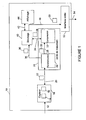
- FIG. figure 1 An example of a system implementing the method of acquisition by a pseudorandom pattern sensor and the digital image processing of the present invention, composed of processing modules interconnected with one another, is presented with reference to FIG. figure 1 .
- a digital camera 10 consists of a color sensor with a pseudo-random pattern 18 according to the invention, a processing unit 24, comprising a reconstruction module 26 and a compression module 32, a storage module 40, a module of FIG. display 44 and an output interface 52.
- An image 14 acquired by the sensor 18 via the link 12 is filtered using the color filter matrix pseudo random 16, which is already included in the sensor.
- the filtered image 22 is transmitted via the link 20 to the processing unit 24, more precisely to the reconstruction module 26, performing the application of the linear reconstruction filters, and the interpolation, within which the reconstruction of the captured image.
- the processing unit 24 is also able to communicate with the sensor 18 via the link 20.
- the reconstructed image in raw format is transmitted to a storage module 40 via link 36 to be saved. Also, the reconstructed image in raw format is directly transmitted to a display module 44 for viewing. Alternatively, the reconstructed images saved in the storage module 40 are transmitted to the display module 44 via the link 42 and be viewed later.
- the reconstructed image 30 is transmitted via the link 28 to a compression module 32 of images in raw format.
- the compression module contains at least one digital encoder.
- the compression module 32 is included in the reconstruction module 26.
- the compressed image 38 is transmitted to the storage module 40 via the link 34.
- the compressed image 38 is transmitted to the display module 44 to be viewed.
- the display module 44 comprises at least one digital decoder capable of interpreting the compressed image 38.
- the compression module retrieves from the storage module 40 a raw reconstructed image for compressing it.
- the reconstructed image 50 is transmitted to an output interface 52, via the link 46.
- the image processed as described above is sent via the link 54 to at least one external digital support.
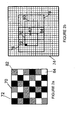
- the acquisition is performed with a matrix 16 and a reduced pattern 70 of size n ⁇ n, with "n" a natural integer which is greater than or equal to at 4.
- the color filter array 16 forming the sensor 18 is comprised of a plurality of identical base patterns 70 replicated without overlap.
- Each of the basic patterns 70 consists of color filters 72, 82, 84 arranged pseudo randomly, so that there is, in each of the basic patterns 70, a variable pitch between two consecutive color filters of the same type in the horizontal and / or vertical directions of the basic pattern.
- the reconstruction implemented is linear and involves a weighting of a neighborhood of pixels 76, of dimension mxm, where m is a natural number greater than n, while reducing the complexity of the filters of reconstruction.
- the basic pattern and the neighborhood are rectangular.
- luminance and chrominance decomposition is applied.
- the method is also realized using the use of a module being devoid of color filter matrices.
- This module allows the acquisition of an achromatic image which is used as a setpoint from which the determination of the coefficients with random pattern by the least squares method is carried out.
- the reconstruction of the image is then performed from the estimated luminance and the three interpolated chromatic components.
- a basic pattern 70 of reduced size is defined at the figure 2a consisting of pixels 72 represented in black (corresponding to the green color), pixels 82 represented in stripes (corresponding to the blue color and pixels 84 represented in white (corresponding to the red color), for example a 6x6 size pattern is composed of a pseudo-random arrangement of color filters, that is to say the step, between two consecutive filters of the same type, is variable in the horizontal or vertical directions of the matrix.
- This basic pattern is applied to blocks of the same size for the entire image.
- This irregular pattern applies to a centered square or hexagonal mesh, for any number of filters and whose filters are of any transmission.
- This pattern is made from the consideration of alternating filters in the vicinity, in order to avoid agglomerates of filters of the same color, thus avoiding the appearance of "false colors”.
- the solution adopted is with two filters 72 and 84 of sensitivity to the wavelength very close (around the green and the red), randomly covering the majority of a base block and with a third filter 82 interspersed pseudo randomly with the maximum sensitivity is in the blue. This configuration approaches that of the human visual system.
- a calculation of the coefficients of the reconstruction filters is performed. This is a calibration step for the implementation of the reconstruction, which is performed one or more times depending on the change in spatial (optical) or spectral (addition of color filters) characteristics of the acquired image. This step is carried out either by a simulation on an image data base, or by a construction and application of a module being devoid of color filter matrix.
- the subtraction of the luminance of the color mosaic is performed.
- a calculation of the color information composed of chrominances encoded in color opposition is applied.
- the new neighborhood weights are used to interpolate the chrominance, that is, the three chromatic components.
- the action of the color mosaic 74 is simulated by removing from this mosaic the missing colors on the color image, resulting in obtaining an intermediate image.
- a luminance image is estimated, as the weighted sum for each pixel of the red, green and blue values of the images of the database, respectively with coefficients pR, pG and pB of the components R, G and B.
- coefficients pR, pG and pB are the proportions of each filter that composes the pseudo-random mosaic.
- the battery coefficients of the thirty-six variable size filters are calculated as the least squares solution of the squared error between the simulated mosaic intermediate image and the estimated luminance.
- an estimate of the luminance filters is based on the use of a second sensor module devoid of color filter matrix.
- the luminance corresponds to a signal that would be measured by the sensor if it was devoid of the matrix of color filters.
- the approach is to use a sensor that lacks the color filter matrix to measure luminance and is provided with the color filter matrix to measure the mosaic of the image database. Several shots of the same scene are made with these two modules, in order to estimate the luminance filter from this database of shots. This approach allows for a configuration of the filters, which best represents the optical and spectral characteristics of the acquisition system.
- the coefficients of the filters being calculated in step II, the reconstruction of the information is carried out block by block 70, 80.
- the calculation of the value of the pixel is carried out using a weighted sum of all the pixels of the neighborhood 76, the same calculation with the thirty six different filters is performed for all the pixels 72, 82 and 84 of the block. This calculation is also performed for the next block 80 (dotted on the figure 2b ), and the next neighborhood 78 (in dotted line on the same figure 2b ), and for the whole of the image 30. Alternatively, this calculation is applied for any block size and neighborhood.
- the reconstruction of the image is done with the sum of the estimated luminance and the interpolated chrominance.
- the process is defined in two stages, at first a decomposition in luminance and chrominance, and in a second time, a recomposition of the image from the estimated luminance and the interpolated chrominance.
- another embodiment of the reconstruction consists in calculating the chrominance as the difference between the luminance and the mosaic 74 of the colors, this corresponds to the use of a color filter. reverse chrominance to that of luminance.
- the low pass filters of the luminance and the high pass of the chrominance define the spectral bands sufficiently separated to substantially reduce the spectral overlap. This is another way of suppressing intermediate spatial frequencies, where the risk of aliasing (spectrum folding in English) is higher.
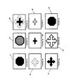
- a second exemplary embodiment of a method of acquiring an image 14 and of reconstructing this image 30, schematized in FIGS. 3a to 3i, is the acquisition of the image with a matrix 16 of color-size filters. equal to that of the image.
- the matrix 16 is as previously described, that is to say that it consists of a plurality of identical basic patterns replicated without overlap.
- Each of the basic patterns consists of color filters arranged pseudo randomly, so that in each of the basic patterns there is a variable pitch between two consecutive color filters of the same type in the horizontal and / or vertical directions of the color pattern. basic pattern.
- Luminance and chrominance decomposition is also applied.
- An adaptive reconstruction of the image from the chrominances brought back to baseband is performed. This reconstruction is carried out via a calculation based on the gradient of the luminance estimated by a standard low-pass filter in R, G and B, the gradient of which indicates whether the interpolation of the chrominances must be made in the vertical or horizontal direction of the 'picture.
- the term "horizontal gradient” refers to a change in lines of the image and by "vertical gradient” an evolution relative to the columns of the image.
- This example also makes it possible to use the sensor 18 and the reconstruction module 26 for the reconstruction of the captured image 14 with the same advantages, by setting up a second embodiment whose steps are presented and the results of the processing are schematized in Figures 3a to 3i.
- FIGS. 3a to 3i are respectively the schematization of Figures 4a (original image 14), 4b (captured image 22), 4c (captured image spectrum 84), 4d (estimated low frequencies containing the luminance 86), 4th (the three chrominances plus the high luminance frequencies 88), 4f (the initial red chrominance plus the high luminance frequencies 90), 4g (interpolated red chrominance 92), 4h (estimated luminance 94 again, from the interpolated chrominances) and 4i (reconstructed image 22).
- An original image 14 ( figure 3a ) is sampled by a matrix 16 of color filters.
- the sampled image 22 ( figure 3b ) has a spectrum 84 ( figure 3c ), whose estimated low frequencies contain luminance 86 ( figure 3d ) and the three chrominances plus the high luminance frequencies 88 ( figure 3e ).
- a demultiplexing of the three chrominances of 88 ( figure 3e ) is performed, for example here is illustrated the initial red chrominance plus the high luminance frequencies 90 ( figure 3f ).
- the three chrominances are then interpolated using the adaptive method, for example the red chrominance 92 ( figure 3g ) is interpolated from the initial red chrominance of 90 ( figure 3f ).
- the luminance 94 ( figure 3h ) is estimated again from the interpolated chrominances, that is to say from the red chrominance 92 and the green and blue chrominances.
- the image 30 is finally reconstructed ( figure 3i ) from the estimated luminance and the three interpolated components of the chrominance.
- the acquisition of the image is performed by a color sensor 18, in which is placed a matrix 16 of color filters.
- the color distribution must be such that the chrominance carriers, defined by the Fourier transform of the modulation functions of each of the three chrominances, form a spectral modulation, advantageously the whitest possible to reduce the effects of coherence of the chrominance on the luminance, for example in the case where the chrominance carriers are not present in the low spatial frequencies of the luminance.
- the treatment starts with the acquisition of the original image 14, in a captured image 22 ( figure 3b ).
- a spectral transformation of the image 22 is applied for example to obtain the spectrum 84 ( figure 3c ).
- the lowest frequencies, the low frequencies of the luminance are estimated by filtering.
- the filter used is normalized in R, G and B, that is to say that its function is to respect at each spatial position, a contribution at pR, pG and pB, respectively for each color R, G and B.
- normalization of the filter takes place so that the sum of the coefficients corresponding to the color filters R, G and B is equal to pR, pG and pB, respectively. estimated luminance.
- the demultiplexing of the image 22 is then applied by isolating the images corresponding to sub-matrices with the same spectral sensitivities, for example at the red chrominance of 90 ( figure 3f ). This operation has the effect of reducing the chrominance carriers to zero spatial frequencies, that is to say in the center of the spectrum.
- Interpolation is performed on the chrominances brought back to baseband.
- the advantage of this method is to be able to use an adaptive interpolation, based on a calculation of the low frequency gradient of the luminance 86 ( figure 3d ) estimated.
- the chrominances interpolated by the adaptive method are removed from the image 22 acquired by the sensor, to recover all the frequency bands of luminance 94 ( figure 3h ). This luminance is then calculated as being the residue of what is not chromatic in the sense of the luminance adaptation.
- the reconstruction of the image 30 is performed from the estimated luminance 94 again ( figure 3i ) and the three interpolated R, G, B chrominances.
- the present invention is not limited to the described embodiments. It is indeed possible to define pseudo-random color filter sensor matrices with different sizes and pattern shapes for the acquisition, the pseudo-random patterns being periodic or non-periodic, for example. Regarding reconstruction, a multitude of processes can be applied, containing different numbers of steps and different types of calculations.
- the reconstruction module can be hosted in an external host machine or integrated into the digital processing unit.
- the real-time reconstruction of the image is partial in a camera, in order to allow the display of the images in real time and to have the possibility of taking successive shots.
- a recording of the captured data is done in raw format and then the complete reconstruction of the colors is performed offline .
- the method also allows the adaptation of the luminance and the implementation of a recursive filtering.
- the present invention is applicable to any type of sensor, whatever the CDD technology (initials of "Charged Coupled Device” in English, or charge transfer device) or CMOS (complementary Metal Oxide Semiconductor circuits) and whatever the size of the sensor.
Landscapes
- Engineering & Computer Science (AREA)
- Multimedia (AREA)
- Signal Processing (AREA)
- Physics & Mathematics (AREA)
- Spectroscopy & Molecular Physics (AREA)
- Color Television Image Signal Generators (AREA)
- Optical Filters (AREA)
- Solid State Image Pick-Up Elements (AREA)
Applications Claiming Priority (2)
| Application Number | Priority Date | Filing Date | Title |
|---|---|---|---|
| FR0704181A FR2917559B1 (fr) | 2007-06-12 | 2007-06-12 | Capteur d'images numeriques,procede d'acquisition et de reconstruction d'images,et systeme de mise en oeuvre |
| PCT/FR2008/000806 WO2009007543A2 (fr) | 2007-06-12 | 2008-06-12 | Capteur d'images numeriques, procede d'acquisition et de reconstruction d'images, et systeme de mise en œuvre |
Publications (2)
| Publication Number | Publication Date |
|---|---|
| EP2160904A2 EP2160904A2 (fr) | 2010-03-10 |
| EP2160904B1 true EP2160904B1 (fr) | 2014-05-21 |
Family
ID=38947707
Family Applications (1)
| Application Number | Title | Priority Date | Filing Date |
|---|---|---|---|
| EP08826272.0A Not-in-force EP2160904B1 (fr) | 2007-06-12 | 2008-06-12 | Capteur d'images numeriques, procede d'acquisition et de reconstruction d'images, et systeme de mise en uvre |
Country Status (5)
| Country | Link |
|---|---|
| US (1) | US8564699B2 (enExample) |
| EP (1) | EP2160904B1 (enExample) |
| JP (3) | JP2010531560A (enExample) |
| FR (1) | FR2917559B1 (enExample) |
| WO (1) | WO2009007543A2 (enExample) |
Cited By (1)
| Publication number | Priority date | Publication date | Assignee | Title |
|---|---|---|---|---|
| EP3763116B1 (fr) * | 2018-03-07 | 2022-01-05 | Centre national de la recherche scientifique | Procede de reconstruction d'une image couleur acquise par un capteur recouvert d'une mosaïque de filtres couleurs |
Families Citing this family (11)
| Publication number | Priority date | Publication date | Assignee | Title |
|---|---|---|---|---|
| JP3468331B2 (ja) | 1996-03-21 | 2003-11-17 | 日立建機株式会社 | 建設機械の干渉防止装置 |
| FR2952183A1 (fr) | 2009-10-30 | 2011-05-06 | St Microelectronics Crolles 2 | Detecteur de matiere biologique ou chimique et matrice de detecteurs correspondante |
| US8761525B2 (en) * | 2009-11-20 | 2014-06-24 | Tripurari Singh | Method and system for compressive color image sampling and reconstruction |
| DE102010041569B4 (de) * | 2010-09-28 | 2017-04-06 | Leica Geosystems Ag | Digitales Kamerasystem, Farbfilterelement für digitales Kamerasystem, Verfahren zur Bestimmung von Abweichungen zwischen den Kameras eines digitalen Kamerasystems sowie Bildverarbeitungseinheit für digitales Kamerasystem |
| KR20120059367A (ko) * | 2010-11-30 | 2012-06-08 | 삼성전자주식회사 | 에너지값을 이용한 이미지 처리 장치와 그 이미지 처리 방법 및 디스플레이 방법 |
| JP6962667B2 (ja) * | 2014-03-27 | 2021-11-05 | 住友建機株式会社 | ショベル及びその制御方法 |
| US10048413B2 (en) | 2016-06-07 | 2018-08-14 | Goodrich Corporation | Imaging systems and methods |
| JP6960802B2 (ja) | 2017-08-24 | 2021-11-05 | 日立建機株式会社 | 作業機械の周囲監視装置 |
| FR3088160B1 (fr) * | 2018-11-06 | 2021-04-02 | Teledyne E2V Semiconductors Sas | Capteur d'image pour la reconnaissance optique de code(s) |
| JP7032287B2 (ja) | 2018-11-21 | 2022-03-08 | 住友建機株式会社 | ショベル |
| US11328386B1 (en) | 2019-11-13 | 2022-05-10 | Gigajot Technology, Inc. | Luminance-guided image de-mosaicing and de-noising |
Family Cites Families (17)
| Publication number | Priority date | Publication date | Assignee | Title |
|---|---|---|---|---|
| JPS6454990A (en) * | 1987-08-26 | 1989-03-02 | Mitsubishi Electric Corp | Color solid-state image pickup device |
| JP4027441B2 (ja) | 1995-12-18 | 2007-12-26 | オリンパス株式会社 | カラー画像撮像装置 |
| JP3935548B2 (ja) * | 1997-02-27 | 2007-06-27 | オリンパス株式会社 | 画像信号処理装置 |
| US6803955B1 (en) * | 1999-03-03 | 2004-10-12 | Olympus Corporation | Imaging device and imaging apparatus |
| US7123299B1 (en) * | 1999-04-15 | 2006-10-17 | Olympus Optical Co., Ltd. | Color image pickup device and color image pickup apparatus including a randomized color coding array |
| JP2000308071A (ja) * | 1999-04-15 | 2000-11-02 | Olympus Optical Co Ltd | カラー撮像素子及びカラー撮像装置 |
| JP2000316166A (ja) * | 1999-05-06 | 2000-11-14 | Olympus Optical Co Ltd | カラー撮像素子及びカラー撮像装置 |
| JP2000341701A (ja) * | 1999-05-25 | 2000-12-08 | Nikon Corp | 補間処理装置および補間処理プログラムを記録した記録媒体 |
| US7088392B2 (en) * | 2001-08-27 | 2006-08-08 | Ramakrishna Kakarala | Digital image system and method for implementing an adaptive demosaicing method |
| JP2003299113A (ja) * | 2002-04-04 | 2003-10-17 | Canon Inc | 撮像装置 |
| US7012643B2 (en) * | 2002-05-08 | 2006-03-14 | Ball Aerospace & Technologies Corp. | One chip, low light level color camera |
| JP4385282B2 (ja) * | 2003-10-31 | 2009-12-16 | ソニー株式会社 | 画像処理装置および画像処理方法 |
| JP2005217979A (ja) * | 2004-01-30 | 2005-08-11 | Canon Inc | 撮像装置、その制御方法および制御プログラム |
| JP4441809B2 (ja) * | 2004-05-20 | 2010-03-31 | 忠 杉木 | カラー固体撮像装置 |
| US8139130B2 (en) * | 2005-07-28 | 2012-03-20 | Omnivision Technologies, Inc. | Image sensor with improved light sensitivity |
| JP4752550B2 (ja) * | 2006-03-14 | 2011-08-17 | ソニー株式会社 | カラー撮像素子の製造方法およびその装置 |
| JP5258352B2 (ja) * | 2007-05-08 | 2013-08-07 | キヤノン株式会社 | 撮像素子、データ処理装置、及び制御方法 |
-
2007
- 2007-06-12 FR FR0704181A patent/FR2917559B1/fr not_active Expired - Fee Related
-
2008
- 2008-06-12 JP JP2010511684A patent/JP2010531560A/ja active Pending
- 2008-06-12 WO PCT/FR2008/000806 patent/WO2009007543A2/fr not_active Ceased
- 2008-06-12 US US12/664,320 patent/US8564699B2/en not_active Expired - Fee Related
- 2008-06-12 EP EP08826272.0A patent/EP2160904B1/fr not_active Not-in-force
-
2013
- 2013-07-22 JP JP2013151459A patent/JP2013243750A/ja active Pending
-
2015
- 2015-06-01 JP JP2015111530A patent/JP6104985B2/ja not_active Expired - Fee Related
Non-Patent Citations (1)
| Title |
|---|
| MANU PARMAR ET AL: "Color filter array design based on a human visual model", PROC. SPIE 5299, COMPUTATIONAL IMAGING II, 21 May 2004 (2004-05-21), XP055072405, Retrieved from the Internet <URL:http://proceedings.spiedigitallibrary.org/proceeding.aspx?articleid=837300> [retrieved on 20130723] * |
Cited By (1)
| Publication number | Priority date | Publication date | Assignee | Title |
|---|---|---|---|---|
| EP3763116B1 (fr) * | 2018-03-07 | 2022-01-05 | Centre national de la recherche scientifique | Procede de reconstruction d'une image couleur acquise par un capteur recouvert d'une mosaïque de filtres couleurs |
Also Published As
| Publication number | Publication date |
|---|---|
| EP2160904A2 (fr) | 2010-03-10 |
| WO2009007543A3 (fr) | 2009-03-12 |
| JP2015188240A (ja) | 2015-10-29 |
| US8564699B2 (en) | 2013-10-22 |
| JP6104985B2 (ja) | 2017-03-29 |
| JP2013243750A (ja) | 2013-12-05 |
| FR2917559B1 (fr) | 2009-12-25 |
| US20100253818A1 (en) | 2010-10-07 |
| WO2009007543A2 (fr) | 2009-01-15 |
| JP2010531560A (ja) | 2010-09-24 |
| FR2917559A1 (fr) | 2008-12-19 |
Similar Documents
| Publication | Publication Date | Title |
|---|---|---|
| EP2160904B1 (fr) | Capteur d'images numeriques, procede d'acquisition et de reconstruction d'images, et systeme de mise en uvre | |
| EP3387824B1 (fr) | Système et procédé d'acquisition d'images visibles et dans le proche infrarouge au moyen d'un capteur matriciel unique | |
| EP2174289B1 (fr) | Procede de traitement d'objet numerique et systeme associe. | |
| EP2426639B1 (fr) | Procédé de démosaïçage d'une image brute numérique, programme d'ordinateur et circuit imageur ou graphique correspondants | |
| Jaiswal et al. | Adaptive multispectral demosaicking based on frequency-domain analysis of spectral correlation | |
| FR3004882A1 (fr) | Dispositif d'acquisition d'images bimode | |
| EP2561681B1 (fr) | Traitement numérique de compensation de signaux issus de photosites d'un capteur couleur. | |
| EP3763116A1 (fr) | Procede de reconstruction d'une image couleur acquise par un capteur recouvert d'une mosaïque de filtres couleurs | |
| Shao et al. | Image demosaicing using content and colour-correlation analysis | |
| WO2012153532A1 (ja) | 撮像装置 | |
| Hirakawa | Cross-talk explained | |
| EP3384459B1 (fr) | Procede de traitement de signaux issus d'une matrice de prise d'images en couleur, et capteur correspondant | |
| Paliy et al. | Denoising and interpolation of noisy Bayer data with adaptive cross-color filters | |
| Monno et al. | N-to-sRGB mapping for single-sensor multispectral imaging | |
| FR3127665A1 (fr) | Procédé de traitement, au sein d’une chaine de traitement d’image, d’une matrice de pixels et dispositif électronique correspondant. | |
| Saito et al. | Sharpening-demosaicking method with a total-variation-based superresolution technique | |
| Gong et al. | Optimal noise-aware imaging with switchable prefilters | |
| Yu | Colour demosaicking method using adaptive cubic convolution interpolation with sequential averaging | |
| Tominaga et al. | Surface reconstruction of oil paintings for digital archiving | |
| Monno et al. | Direct spatio-spectral datacube reconstruction from raw data using a spatially adaptive spatio-spectral basis | |
| CN112399164A (zh) | 一种低照度条件下含有近红外彩色图像颜色复原方法 | |
| Komatsu et al. | Super-resolution sharpening-demosaicking method for removing image blurs caused by an optical low-pass filter | |
| Lee et al. | A cost-effective demosaicked image enhancement for a single chip CMOS image sensor | |
| Journes | A study of image quality assessment and color image reconstruction algorithms for mono-sensor camera | |
| Kachatkou et al. | High dynamic range colour imaging using complementary metal-oxide-semiconductor (CMOS) sensors with non-destructive readout |
Legal Events
| Date | Code | Title | Description |
|---|---|---|---|
| PUAI | Public reference made under article 153(3) epc to a published international application that has entered the european phase |
Free format text: ORIGINAL CODE: 0009012 |
|
| 17P | Request for examination filed |
Effective date: 20091209 |
|
| AK | Designated contracting states |
Kind code of ref document: A2 Designated state(s): AT BE BG CH CY CZ DE DK EE ES FI FR GB GR HR HU IE IS IT LI LT LU LV MC MT NL NO PL PT RO SE SI SK TR |
|
| AX | Request for extension of the european patent |
Extension state: AL BA MK RS |
|
| 17Q | First examination report despatched |
Effective date: 20110726 |
|
| DAX | Request for extension of the european patent (deleted) | ||
| GRAP | Despatch of communication of intention to grant a patent |
Free format text: ORIGINAL CODE: EPIDOSNIGR1 |
|
| GRAS | Grant fee paid |
Free format text: ORIGINAL CODE: EPIDOSNIGR3 |
|
| RIN1 | Information on inventor provided before grant (corrected) |
Inventor name: ALLEYSSON, DAVID Inventor name: HERAUT, JEANNY Inventor name: CHAIX DE LAVARENE, BRICE |
|
| GRAA | (expected) grant |
Free format text: ORIGINAL CODE: 0009210 |
|
| INTG | Intention to grant announced |
Effective date: 20140326 |
|
| RAP3 | Party data changed (applicant data changed or rights of an application transferred) |
Owner name: UNIVERSITE JOSEPH FOURIER Owner name: CENTRE NATIONAL DE LA RECHERCHE SCIENTIFIQUE (CNRS |
|
| AK | Designated contracting states |
Kind code of ref document: B1 Designated state(s): AT BE BG CH CY CZ DE DK EE ES FI FR GB GR HR HU IE IS IT LI LT LU LV MC MT NL NO PL PT RO SE SI SK TR |
|
| REG | Reference to a national code |
Ref country code: GB Ref legal event code: FG4D Free format text: NOT ENGLISH |
|
| REG | Reference to a national code |
Ref country code: CH Ref legal event code: EP |
|
| REG | Reference to a national code |
Ref country code: AT Ref legal event code: REF Ref document number: 670098 Country of ref document: AT Kind code of ref document: T Effective date: 20140615 |
|
| REG | Reference to a national code |
Ref country code: IE Ref legal event code: FG4D Free format text: LANGUAGE OF EP DOCUMENT: FRENCH |
|
| REG | Reference to a national code |
Ref country code: DE Ref legal event code: R096 Ref document number: 602008032443 Country of ref document: DE Effective date: 20140703 |
|
| REG | Reference to a national code |
Ref country code: NL Ref legal event code: T3 |
|
| REG | Reference to a national code |
Ref country code: AT Ref legal event code: MK05 Ref document number: 670098 Country of ref document: AT Kind code of ref document: T Effective date: 20140521 |
|
| REG | Reference to a national code |
Ref country code: LT Ref legal event code: MG4D |
|
| PG25 | Lapsed in a contracting state [announced via postgrant information from national office to epo] |
Ref country code: NO Free format text: LAPSE BECAUSE OF FAILURE TO SUBMIT A TRANSLATION OF THE DESCRIPTION OR TO PAY THE FEE WITHIN THE PRESCRIBED TIME-LIMIT Effective date: 20140821 Ref country code: IS Free format text: LAPSE BECAUSE OF FAILURE TO SUBMIT A TRANSLATION OF THE DESCRIPTION OR TO PAY THE FEE WITHIN THE PRESCRIBED TIME-LIMIT Effective date: 20140921 Ref country code: GR Free format text: LAPSE BECAUSE OF FAILURE TO SUBMIT A TRANSLATION OF THE DESCRIPTION OR TO PAY THE FEE WITHIN THE PRESCRIBED TIME-LIMIT Effective date: 20140822 Ref country code: LT Free format text: LAPSE BECAUSE OF FAILURE TO SUBMIT A TRANSLATION OF THE DESCRIPTION OR TO PAY THE FEE WITHIN THE PRESCRIBED TIME-LIMIT Effective date: 20140521 Ref country code: FI Free format text: LAPSE BECAUSE OF FAILURE TO SUBMIT A TRANSLATION OF THE DESCRIPTION OR TO PAY THE FEE WITHIN THE PRESCRIBED TIME-LIMIT Effective date: 20140521 |
|
| PG25 | Lapsed in a contracting state [announced via postgrant information from national office to epo] |
Ref country code: HR Free format text: LAPSE BECAUSE OF FAILURE TO SUBMIT A TRANSLATION OF THE DESCRIPTION OR TO PAY THE FEE WITHIN THE PRESCRIBED TIME-LIMIT Effective date: 20140521 Ref country code: ES Free format text: LAPSE BECAUSE OF FAILURE TO SUBMIT A TRANSLATION OF THE DESCRIPTION OR TO PAY THE FEE WITHIN THE PRESCRIBED TIME-LIMIT Effective date: 20140521 Ref country code: SE Free format text: LAPSE BECAUSE OF FAILURE TO SUBMIT A TRANSLATION OF THE DESCRIPTION OR TO PAY THE FEE WITHIN THE PRESCRIBED TIME-LIMIT Effective date: 20140521 Ref country code: PL Free format text: LAPSE BECAUSE OF FAILURE TO SUBMIT A TRANSLATION OF THE DESCRIPTION OR TO PAY THE FEE WITHIN THE PRESCRIBED TIME-LIMIT Effective date: 20140521 Ref country code: AT Free format text: LAPSE BECAUSE OF FAILURE TO SUBMIT A TRANSLATION OF THE DESCRIPTION OR TO PAY THE FEE WITHIN THE PRESCRIBED TIME-LIMIT Effective date: 20140521 Ref country code: LV Free format text: LAPSE BECAUSE OF FAILURE TO SUBMIT A TRANSLATION OF THE DESCRIPTION OR TO PAY THE FEE WITHIN THE PRESCRIBED TIME-LIMIT Effective date: 20140521 |
|
| PG25 | Lapsed in a contracting state [announced via postgrant information from national office to epo] |
Ref country code: PT Free format text: LAPSE BECAUSE OF FAILURE TO SUBMIT A TRANSLATION OF THE DESCRIPTION OR TO PAY THE FEE WITHIN THE PRESCRIBED TIME-LIMIT Effective date: 20140922 |
|
| PG25 | Lapsed in a contracting state [announced via postgrant information from national office to epo] |
Ref country code: DK Free format text: LAPSE BECAUSE OF FAILURE TO SUBMIT A TRANSLATION OF THE DESCRIPTION OR TO PAY THE FEE WITHIN THE PRESCRIBED TIME-LIMIT Effective date: 20140521 Ref country code: CZ Free format text: LAPSE BECAUSE OF FAILURE TO SUBMIT A TRANSLATION OF THE DESCRIPTION OR TO PAY THE FEE WITHIN THE PRESCRIBED TIME-LIMIT Effective date: 20140521 Ref country code: RO Free format text: LAPSE BECAUSE OF FAILURE TO SUBMIT A TRANSLATION OF THE DESCRIPTION OR TO PAY THE FEE WITHIN THE PRESCRIBED TIME-LIMIT Effective date: 20140521 Ref country code: EE Free format text: LAPSE BECAUSE OF FAILURE TO SUBMIT A TRANSLATION OF THE DESCRIPTION OR TO PAY THE FEE WITHIN THE PRESCRIBED TIME-LIMIT Effective date: 20140521 Ref country code: SK Free format text: LAPSE BECAUSE OF FAILURE TO SUBMIT A TRANSLATION OF THE DESCRIPTION OR TO PAY THE FEE WITHIN THE PRESCRIBED TIME-LIMIT Effective date: 20140521 |
|
| REG | Reference to a national code |
Ref country code: CH Ref legal event code: PL |
|
| REG | Reference to a national code |
Ref country code: DE Ref legal event code: R097 Ref document number: 602008032443 Country of ref document: DE |
|
| REG | Reference to a national code |
Ref country code: IE Ref legal event code: MM4A |
|
| PLBE | No opposition filed within time limit |
Free format text: ORIGINAL CODE: 0009261 |
|
| STAA | Information on the status of an ep patent application or granted ep patent |
Free format text: STATUS: NO OPPOSITION FILED WITHIN TIME LIMIT |
|
| 26N | No opposition filed |
Effective date: 20150224 |
|
| PG25 | Lapsed in a contracting state [announced via postgrant information from national office to epo] |
Ref country code: IE Free format text: LAPSE BECAUSE OF NON-PAYMENT OF DUE FEES Effective date: 20140612 Ref country code: IT Free format text: LAPSE BECAUSE OF FAILURE TO SUBMIT A TRANSLATION OF THE DESCRIPTION OR TO PAY THE FEE WITHIN THE PRESCRIBED TIME-LIMIT Effective date: 20140521 Ref country code: LI Free format text: LAPSE BECAUSE OF NON-PAYMENT OF DUE FEES Effective date: 20140630 Ref country code: CH Free format text: LAPSE BECAUSE OF NON-PAYMENT OF DUE FEES Effective date: 20140630 |
|
| REG | Reference to a national code |
Ref country code: FR Ref legal event code: PLFP Year of fee payment: 8 |
|
| REG | Reference to a national code |
Ref country code: DE Ref legal event code: R097 Ref document number: 602008032443 Country of ref document: DE Effective date: 20150224 |
|
| PG25 | Lapsed in a contracting state [announced via postgrant information from national office to epo] |
Ref country code: SI Free format text: LAPSE BECAUSE OF FAILURE TO SUBMIT A TRANSLATION OF THE DESCRIPTION OR TO PAY THE FEE WITHIN THE PRESCRIBED TIME-LIMIT Effective date: 20140521 |
|
| PG25 | Lapsed in a contracting state [announced via postgrant information from national office to epo] |
Ref country code: MT Free format text: LAPSE BECAUSE OF FAILURE TO SUBMIT A TRANSLATION OF THE DESCRIPTION OR TO PAY THE FEE WITHIN THE PRESCRIBED TIME-LIMIT Effective date: 20140521 |
|
| PG25 | Lapsed in a contracting state [announced via postgrant information from national office to epo] |
Ref country code: MC Free format text: LAPSE BECAUSE OF FAILURE TO SUBMIT A TRANSLATION OF THE DESCRIPTION OR TO PAY THE FEE WITHIN THE PRESCRIBED TIME-LIMIT Effective date: 20140521 |
|
| REG | Reference to a national code |
Ref country code: FR Ref legal event code: PLFP Year of fee payment: 9 |
|
| PG25 | Lapsed in a contracting state [announced via postgrant information from national office to epo] |
Ref country code: BG Free format text: LAPSE BECAUSE OF FAILURE TO SUBMIT A TRANSLATION OF THE DESCRIPTION OR TO PAY THE FEE WITHIN THE PRESCRIBED TIME-LIMIT Effective date: 20140521 |
|
| PG25 | Lapsed in a contracting state [announced via postgrant information from national office to epo] |
Ref country code: CY Free format text: LAPSE BECAUSE OF FAILURE TO SUBMIT A TRANSLATION OF THE DESCRIPTION OR TO PAY THE FEE WITHIN THE PRESCRIBED TIME-LIMIT Effective date: 20140521 |
|
| PG25 | Lapsed in a contracting state [announced via postgrant information from national office to epo] |
Ref country code: TR Free format text: LAPSE BECAUSE OF FAILURE TO SUBMIT A TRANSLATION OF THE DESCRIPTION OR TO PAY THE FEE WITHIN THE PRESCRIBED TIME-LIMIT Effective date: 20140521 Ref country code: BE Free format text: LAPSE BECAUSE OF FAILURE TO SUBMIT A TRANSLATION OF THE DESCRIPTION OR TO PAY THE FEE WITHIN THE PRESCRIBED TIME-LIMIT Effective date: 20140630 Ref country code: LU Free format text: LAPSE BECAUSE OF NON-PAYMENT OF DUE FEES Effective date: 20140612 Ref country code: HU Free format text: LAPSE BECAUSE OF FAILURE TO SUBMIT A TRANSLATION OF THE DESCRIPTION OR TO PAY THE FEE WITHIN THE PRESCRIBED TIME-LIMIT; INVALID AB INITIO Effective date: 20080612 |
|
| REG | Reference to a national code |
Ref country code: FR Ref legal event code: PLFP Year of fee payment: 10 |
|
| REG | Reference to a national code |
Ref country code: FR Ref legal event code: PLFP Year of fee payment: 11 |
|
| REG | Reference to a national code |
Ref country code: DE Ref legal event code: R079 Ref document number: 602008032443 Country of ref document: DE Free format text: PREVIOUS MAIN CLASS: H04N0009040000 Ipc: H04N0023100000 |
|
| REG | Reference to a national code |
Ref country code: GB Ref legal event code: 732E Free format text: REGISTERED BETWEEN 20230914 AND 20230920 |
|
| REG | Reference to a national code |
Ref country code: NL Ref legal event code: PD Owner name: UNIVERSITE GRENOBLE ALPES; FR Free format text: DETAILS ASSIGNMENT: CHANGE OF OWNER(S), MERGE; FORMER OWNER NAME: UNIVERSITE JOSEPH FOURIER Effective date: 20231019 |
|
| REG | Reference to a national code |
Ref country code: DE Ref legal event code: R081 Ref document number: 602008032443 Country of ref document: DE Owner name: UNIVERSITE GRENOBLE ALPES, FR Free format text: FORMER OWNERS: CENTRE NATIONAL DE LA RECHERCHE SCIENTIFIQUE (CNRS), PARIS, FR; UNIVERSITE JOSEPH FOURIER, GRENOBLE, FR Ref country code: DE Ref legal event code: R081 Ref document number: 602008032443 Country of ref document: DE Owner name: CENTRE NATIONAL DE LA RECHERCHE SCIENTIFIQUE (, FR Free format text: FORMER OWNERS: CENTRE NATIONAL DE LA RECHERCHE SCIENTIFIQUE (CNRS), PARIS, FR; UNIVERSITE JOSEPH FOURIER, GRENOBLE, FR |
|
| PGFP | Annual fee paid to national office [announced via postgrant information from national office to epo] |
Ref country code: GB Payment date: 20240627 Year of fee payment: 17 |
|
| PGFP | Annual fee paid to national office [announced via postgrant information from national office to epo] |
Ref country code: NL Payment date: 20240626 Year of fee payment: 17 |
|
| PGFP | Annual fee paid to national office [announced via postgrant information from national office to epo] |
Ref country code: FR Payment date: 20240627 Year of fee payment: 17 |
|
| PGFP | Annual fee paid to national office [announced via postgrant information from national office to epo] |
Ref country code: DE Payment date: 20240729 Year of fee payment: 17 |
|
| REG | Reference to a national code |
Ref country code: DE Ref legal event code: R119 Ref document number: 602008032443 Country of ref document: DE |
|
| REG | Reference to a national code |
Ref country code: NL Ref legal event code: MM Effective date: 20250701 |
|
| GBPC | Gb: european patent ceased through non-payment of renewal fee |
Effective date: 20250612 |
|
| PG25 | Lapsed in a contracting state [announced via postgrant information from national office to epo] |
Ref country code: NL Free format text: LAPSE BECAUSE OF NON-PAYMENT OF DUE FEES Effective date: 20250701 |
|
| PG25 | Lapsed in a contracting state [announced via postgrant information from national office to epo] |
Ref country code: GB Free format text: LAPSE BECAUSE OF NON-PAYMENT OF DUE FEES Effective date: 20250612 |
|
| PG25 | Lapsed in a contracting state [announced via postgrant information from national office to epo] |
Ref country code: DE Free format text: LAPSE BECAUSE OF NON-PAYMENT OF DUE FEES Effective date: 20260101 |
|
| PG25 | Lapsed in a contracting state [announced via postgrant information from national office to epo] |
Ref country code: FR Free format text: LAPSE BECAUSE OF NON-PAYMENT OF DUE FEES Effective date: 20250630 |