EP2160904B1 - Digital image sensor, image capture and reconstruction method and system for implementing same - Google Patents
Digital image sensor, image capture and reconstruction method and system for implementing same Download PDFInfo
- Publication number
- EP2160904B1 EP2160904B1 EP08826272.0A EP08826272A EP2160904B1 EP 2160904 B1 EP2160904 B1 EP 2160904B1 EP 08826272 A EP08826272 A EP 08826272A EP 2160904 B1 EP2160904 B1 EP 2160904B1
- Authority
- EP
- European Patent Office
- Prior art keywords
- image
- reconstruction
- luminance
- sensor
- acquisition
- Prior art date
- Legal status (The legal status is an assumption and is not a legal conclusion. Google has not performed a legal analysis and makes no representation as to the accuracy of the status listed.)
- Active
Links
- 238000000034 method Methods 0.000 title claims description 57
- 238000004364 calculation method Methods 0.000 claims description 20
- 239000003086 colorant Substances 0.000 claims description 16
- 238000012545 processing Methods 0.000 claims description 15
- 230000006835 compression Effects 0.000 claims description 12
- 238000007906 compression Methods 0.000 claims description 12
- 230000003044 adaptive effect Effects 0.000 claims description 10
- 238000000354 decomposition reaction Methods 0.000 claims description 8
- 238000001228 spectrum Methods 0.000 claims description 8
- 239000000969 carrier Substances 0.000 claims description 5
- 238000001914 filtration Methods 0.000 claims description 4
- 230000001788 irregular Effects 0.000 claims description 3
- 238000012546 transfer Methods 0.000 claims description 3
- 239000011159 matrix material Substances 0.000 description 30
- 230000003595 spectral effect Effects 0.000 description 12
- 230000000737 periodic effect Effects 0.000 description 8
- 230000035945 sensitivity Effects 0.000 description 6
- 230000008569 process Effects 0.000 description 5
- 230000000007 visual effect Effects 0.000 description 5
- 230000008901 benefit Effects 0.000 description 4
- 238000010276 construction Methods 0.000 description 4
- 238000013459 approach Methods 0.000 description 3
- 230000000694 effects Effects 0.000 description 3
- 238000012805 post-processing Methods 0.000 description 3
- 230000009467 reduction Effects 0.000 description 3
- 230000006978 adaptation Effects 0.000 description 2
- 230000008859 change Effects 0.000 description 2
- 230000006870 function Effects 0.000 description 2
- 238000005259 measurement Methods 0.000 description 2
- 230000003287 optical effect Effects 0.000 description 2
- 230000008447 perception Effects 0.000 description 2
- 230000010076 replication Effects 0.000 description 2
- 238000005070 sampling Methods 0.000 description 2
- 238000004088 simulation Methods 0.000 description 2
- 238000010521 absorption reaction Methods 0.000 description 1
- 230000009471 action Effects 0.000 description 1
- 230000005540 biological transmission Effects 0.000 description 1
- 230000000052 comparative effect Effects 0.000 description 1
- 230000000295 complement effect Effects 0.000 description 1
- 230000007547 defect Effects 0.000 description 1
- 238000013461 design Methods 0.000 description 1
- 238000005516 engineering process Methods 0.000 description 1
- 230000006872 improvement Effects 0.000 description 1
- 229910044991 metal oxide Inorganic materials 0.000 description 1
- 150000004706 metal oxides Chemical class 0.000 description 1
- 238000010606 normalization Methods 0.000 description 1
- 238000005457 optimization Methods 0.000 description 1
- 238000007781 pre-processing Methods 0.000 description 1
- 230000002441 reversible effect Effects 0.000 description 1
- 238000010187 selection method Methods 0.000 description 1
- 239000004065 semiconductor Substances 0.000 description 1
- 230000009466 transformation Effects 0.000 description 1
- 238000012800 visualization Methods 0.000 description 1
Images

Classifications
-
- H—ELECTRICITY
- H04—ELECTRIC COMMUNICATION TECHNIQUE
- H04N—PICTORIAL COMMUNICATION, e.g. TELEVISION
- H04N23/00—Cameras or camera modules comprising electronic image sensors; Control thereof
- H04N23/80—Camera processing pipelines; Components thereof
- H04N23/84—Camera processing pipelines; Components thereof for processing colour signals
- H04N23/843—Demosaicing, e.g. interpolating colour pixel values
-
- H—ELECTRICITY
- H04—ELECTRIC COMMUNICATION TECHNIQUE
- H04N—PICTORIAL COMMUNICATION, e.g. TELEVISION
- H04N25/00—Circuitry of solid-state image sensors [SSIS]; Control thereof
- H04N25/10—Circuitry of solid-state image sensors [SSIS]; Control thereof for transforming different wavelengths into image signals
- H04N25/11—Arrangement of colour filter arrays [CFA]; Filter mosaics
- H04N25/13—Arrangement of colour filter arrays [CFA]; Filter mosaics characterised by the spectral characteristics of the filter elements
- H04N25/134—Arrangement of colour filter arrays [CFA]; Filter mosaics characterised by the spectral characteristics of the filter elements based on three different wavelength filter elements
-
- H—ELECTRICITY
- H04—ELECTRIC COMMUNICATION TECHNIQUE
- H04N—PICTORIAL COMMUNICATION, e.g. TELEVISION
- H04N2209/00—Details of colour television systems
- H04N2209/04—Picture signal generators
- H04N2209/041—Picture signal generators using solid-state devices
- H04N2209/042—Picture signal generators using solid-state devices having a single pick-up sensor
- H04N2209/045—Picture signal generators using solid-state devices having a single pick-up sensor using mosaic colour filter
Definitions
- the present invention relates to a color sensor dedicated to the acquisition of images, a method for acquiring and reconstructing images, and a system for implementing this method.
- the present invention is in the field of digital image processing and image sequences, during their acquisition by a camera and their reconstruction and backup in raw or compressed format.
- the acquisition of color images includes post-acquisition post-processing for the improvement of the quality of the digital images captured, in downlink with systems compression of images and representation of color images.
- each color filter is a transparent component that passes part of the light and absorbs another, the spectral distribution of the transparency defines the color of the filter.
- the captured images are composed of "pixels", the pixel representing a digital component of the image, characterized by its position (line / column) in the image and by its numerical value, corresponding to a level of gray or color.
- size of the image means the number of lines multiplied by the number of columns, that is to say the number of pixels.
- horizontal / vertical are generally used respectively to determine the size of an image in height (number of lines) and in width (number of columns).
- the color filter matrix gives each pixel of the sensor a different spectral sensitivity to allow the representation of the color.
- this method only one color is sampled at each pixel. Consequently, a step of demosaicing (that is to say, interpolation of the three components of the color "RGB, Red, Green, Blue” in English, so red, green and blue), or estimation of the luminance and interpolation of the chrominances, are necessary to reconstruct a color image having three spectral sensitivity per pixel.
- luminance means the achromatic component of the image
- chrominance or “chrominance” or “three components of the chrominance”
- the chromatic component of the image being devoid of the information luminance.
- the most widely used color filter matrix currently in a sensor is the CFA ("Color Filter Array" in English, table or matrix of color filters), called Bayer.
- This matrix is periodic and consists of a regular alternation, red and green pixels every other line, and an alternation of green and blue pixels on the other line.
- This matrix The major problem of this matrix is that the interpolation generates visible artifacts that affect the visual quality after the reconstruction of the image.
- One of the techniques to reduce the generation of artifacts is to use four photosites to reconstruct a single pixel. Each photosite represents a photoelectric cell, this photosite being sensitive to the luminous intensity in a wavelength range (red, green or blue) that it translates by producing a small electric current relative to the spatial sensitivity. The combination of the currents of four photosites allows the construction of the three colors of the pixel.
- this technique increases the complexity of the sensor because the number of pixels useful for a digital image is reduced by a factor of four in comparison with the number of photosites.
- the complexity represents the consumption of hardware and computer resources, such as, for example, the speed of calculation, the size of the operational memory for the execution of the method, the size of the memory for saving the results, the power consumption of computing and in computing time.
- the complexity of a camera acquisition system is also related to the hardware components, such as the sensor in terms of performance, robustness, size, and cost.
- a sensor comprising a random arrangement is for example known from the publication of Chaix de Laverne et al. "Uniform non-linear processing for the reconstruction of a randomly distributed chromatic mosaic" of the patent US 7123299 B1 or the patent application US 2003/0210332 .
- a sensor formed by the repetition of a basic pattern comprising a random or non-periodic arrangement is known from the patent application JP-H-09 168,157 or the "color filter array design based on a human visual model” publication.
- the invention aims to overcome this disadvantage of the state of the art.
- the idea underlying the invention is to combine the advantage of the random distribution that reduces artifacts, while maintaining a certain regularity in the matrix forming the sensor for the interpolation of colors missing is not too complex.
- the present invention therefore aims to overcome the compromise between the complexity of an acquisition apparatus in connection with the complexity of the reconstruction of a captured image and the quality of this image, while tending towards a high quality of the image, corresponding to the subjective perception of the human eye.
- the present invention proceeds from the model of random color distribution in the human eye to allow the increase of the quality of the image perceived by the reduction of artifacts.
- the invention proposes a pseudo-random arrangement (hereinafter referred to as "non-periodic") of the color filters on the surface of a sensor, the pseudo-random sampling not being constrained to the phenomenon of spectral folding, reduced by therefore the consistency of the errors generated.
- pseudo random pattern is meant a pattern of a sensor comprising color filters arranged with an irregular arrangement, previously undetermined, the qualifier “pseudo” being used because a purely random character is not reachable by computer processing, performed by digital computers, which are deterministic devices.
- the present invention relates to a digital image acquisition sensor according to claim 1.
- pseudo-random basic patterns allows reduction of the artifacts, and replication without overlapping of these basic patterns introduces a certain regularity which facilitates the interpolation of the colors.
- limiting the coherence of the mixing of the spatial and chromatic information in the representation of the image reduces the occurrence of artifacts having an impact on the image quality.
- the senor comprises a matrix of color filters, the basic pattern of the color filters is equal to or greater than 4x4 pixels of an image and is smaller than the size of this image;
- the invention also relates to a method for acquiring and reconstructing digital image sequences, said images being filtered during their acquisition by said sensor using said color filter matrix, thereby performing an acquisition of the red components. , green and blue for a reconstruction of at least one image, from said acquired components of each image.
- the estimation of the coefficients of the luminance linear filter realized by means of a sensor being devoid of color filter matrix, with which an achromatic image is captured, represents an alternative to the calculation of the coefficients by the least squares method of the quadratic error between a simulated mosaic intermediate image and an estimated luminance.
- An image database is a collection of color images with three colors: red, green, and blue at each pixel in the image. This database comes from a system with three sensors to sample the three colors at each spatial position.
- a mosaic of the image database represents the simulation of the effect of this mosaic of colors on the image data base. To get a mosaic of the image database, pixel colors that are not present in this mosaic at the considered position are artificially deleted.
- the gradient calculation is adapted according to the neighborhood of each pixel.
- the present invention utilizes this common property of all mosaics, i.e. the luminance is localized in baseband, and thus proposes a gradient calculation on the low frequency components of the luminance which is uniform over the entire area. 'picture. This calculation takes advantage of gradient-based contours on the low-frequency components of luminance for better interpolation of chrominance.
- the invention also relates to a system for acquiring and reconstructing digital image sequences for implementing the method.
- This system is composed of digital acquisition and processing modules connected to each other, comprising at least one color sensor with pseudo-random pattern, a compression module in connection with a reconstruction module, a storage module, a display module. and an output interface.
- the present invention proposes a solution that is very well adapted to the implementation on media having size constraints and processing capacities, such as those containing embedded applications, for example mobile phones, surveillance cameras, or mini acquisition cameras such as cyber cameras (English webcams).
- the present invention is directed to any system for acquiring and processing color images (for example high-definition cameras, photophones, satellites), and is also suitable for pre-processing for any format and compression system. images or digital video sequences.
- the present invention is an alternative of the most widespread method currently, that is to say the so-called Bayer method, according to which the contours of the image are used for a better interpolation of the chrominance, the contours being calculated by gradient on the low frequency components of the luminance.
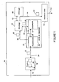
- FIG. figure 1 An example of a system implementing the method of acquisition by a pseudorandom pattern sensor and the digital image processing of the present invention, composed of processing modules interconnected with one another, is presented with reference to FIG. figure 1 .
- a digital camera 10 consists of a color sensor with a pseudo-random pattern 18 according to the invention, a processing unit 24, comprising a reconstruction module 26 and a compression module 32, a storage module 40, a module of FIG. display 44 and an output interface 52.
- An image 14 acquired by the sensor 18 via the link 12 is filtered using the color filter matrix pseudo random 16, which is already included in the sensor.
- the filtered image 22 is transmitted via the link 20 to the processing unit 24, more precisely to the reconstruction module 26, performing the application of the linear reconstruction filters, and the interpolation, within which the reconstruction of the captured image.
- the processing unit 24 is also able to communicate with the sensor 18 via the link 20.
- the reconstructed image in raw format is transmitted to a storage module 40 via link 36 to be saved. Also, the reconstructed image in raw format is directly transmitted to a display module 44 for viewing. Alternatively, the reconstructed images saved in the storage module 40 are transmitted to the display module 44 via the link 42 and be viewed later.
- the reconstructed image 30 is transmitted via the link 28 to a compression module 32 of images in raw format.
- the compression module contains at least one digital encoder.
- the compression module 32 is included in the reconstruction module 26.
- the compressed image 38 is transmitted to the storage module 40 via the link 34.
- the compressed image 38 is transmitted to the display module 44 to be viewed.
- the display module 44 comprises at least one digital decoder capable of interpreting the compressed image 38.
- the compression module retrieves from the storage module 40 a raw reconstructed image for compressing it.
- the reconstructed image 50 is transmitted to an output interface 52, via the link 46.
- the image processed as described above is sent via the link 54 to at least one external digital support.
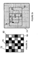
- the acquisition is performed with a matrix 16 and a reduced pattern 70 of size n ⁇ n, with "n" a natural integer which is greater than or equal to at 4.
- the color filter array 16 forming the sensor 18 is comprised of a plurality of identical base patterns 70 replicated without overlap.
- Each of the basic patterns 70 consists of color filters 72, 82, 84 arranged pseudo randomly, so that there is, in each of the basic patterns 70, a variable pitch between two consecutive color filters of the same type in the horizontal and / or vertical directions of the basic pattern.
- the reconstruction implemented is linear and involves a weighting of a neighborhood of pixels 76, of dimension mxm, where m is a natural number greater than n, while reducing the complexity of the filters of reconstruction.
- the basic pattern and the neighborhood are rectangular.
- luminance and chrominance decomposition is applied.
- the method is also realized using the use of a module being devoid of color filter matrices.
- This module allows the acquisition of an achromatic image which is used as a setpoint from which the determination of the coefficients with random pattern by the least squares method is carried out.
- the reconstruction of the image is then performed from the estimated luminance and the three interpolated chromatic components.
- a basic pattern 70 of reduced size is defined at the figure 2a consisting of pixels 72 represented in black (corresponding to the green color), pixels 82 represented in stripes (corresponding to the blue color and pixels 84 represented in white (corresponding to the red color), for example a 6x6 size pattern is composed of a pseudo-random arrangement of color filters, that is to say the step, between two consecutive filters of the same type, is variable in the horizontal or vertical directions of the matrix.
- This basic pattern is applied to blocks of the same size for the entire image.
- This irregular pattern applies to a centered square or hexagonal mesh, for any number of filters and whose filters are of any transmission.
- This pattern is made from the consideration of alternating filters in the vicinity, in order to avoid agglomerates of filters of the same color, thus avoiding the appearance of "false colors”.
- the solution adopted is with two filters 72 and 84 of sensitivity to the wavelength very close (around the green and the red), randomly covering the majority of a base block and with a third filter 82 interspersed pseudo randomly with the maximum sensitivity is in the blue. This configuration approaches that of the human visual system.
- a calculation of the coefficients of the reconstruction filters is performed. This is a calibration step for the implementation of the reconstruction, which is performed one or more times depending on the change in spatial (optical) or spectral (addition of color filters) characteristics of the acquired image. This step is carried out either by a simulation on an image data base, or by a construction and application of a module being devoid of color filter matrix.
- the subtraction of the luminance of the color mosaic is performed.
- a calculation of the color information composed of chrominances encoded in color opposition is applied.
- the new neighborhood weights are used to interpolate the chrominance, that is, the three chromatic components.
- the action of the color mosaic 74 is simulated by removing from this mosaic the missing colors on the color image, resulting in obtaining an intermediate image.
- a luminance image is estimated, as the weighted sum for each pixel of the red, green and blue values of the images of the database, respectively with coefficients pR, pG and pB of the components R, G and B.
- coefficients pR, pG and pB are the proportions of each filter that composes the pseudo-random mosaic.
- the battery coefficients of the thirty-six variable size filters are calculated as the least squares solution of the squared error between the simulated mosaic intermediate image and the estimated luminance.
- an estimate of the luminance filters is based on the use of a second sensor module devoid of color filter matrix.
- the luminance corresponds to a signal that would be measured by the sensor if it was devoid of the matrix of color filters.
- the approach is to use a sensor that lacks the color filter matrix to measure luminance and is provided with the color filter matrix to measure the mosaic of the image database. Several shots of the same scene are made with these two modules, in order to estimate the luminance filter from this database of shots. This approach allows for a configuration of the filters, which best represents the optical and spectral characteristics of the acquisition system.
- the coefficients of the filters being calculated in step II, the reconstruction of the information is carried out block by block 70, 80.
- the calculation of the value of the pixel is carried out using a weighted sum of all the pixels of the neighborhood 76, the same calculation with the thirty six different filters is performed for all the pixels 72, 82 and 84 of the block. This calculation is also performed for the next block 80 (dotted on the figure 2b ), and the next neighborhood 78 (in dotted line on the same figure 2b ), and for the whole of the image 30. Alternatively, this calculation is applied for any block size and neighborhood.
- the reconstruction of the image is done with the sum of the estimated luminance and the interpolated chrominance.
- the process is defined in two stages, at first a decomposition in luminance and chrominance, and in a second time, a recomposition of the image from the estimated luminance and the interpolated chrominance.
- another embodiment of the reconstruction consists in calculating the chrominance as the difference between the luminance and the mosaic 74 of the colors, this corresponds to the use of a color filter. reverse chrominance to that of luminance.
- the low pass filters of the luminance and the high pass of the chrominance define the spectral bands sufficiently separated to substantially reduce the spectral overlap. This is another way of suppressing intermediate spatial frequencies, where the risk of aliasing (spectrum folding in English) is higher.
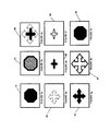
- a second exemplary embodiment of a method of acquiring an image 14 and of reconstructing this image 30, schematized in FIGS. 3a to 3i, is the acquisition of the image with a matrix 16 of color-size filters. equal to that of the image.
- the matrix 16 is as previously described, that is to say that it consists of a plurality of identical basic patterns replicated without overlap.
- Each of the basic patterns consists of color filters arranged pseudo randomly, so that in each of the basic patterns there is a variable pitch between two consecutive color filters of the same type in the horizontal and / or vertical directions of the color pattern. basic pattern.
- Luminance and chrominance decomposition is also applied.
- An adaptive reconstruction of the image from the chrominances brought back to baseband is performed. This reconstruction is carried out via a calculation based on the gradient of the luminance estimated by a standard low-pass filter in R, G and B, the gradient of which indicates whether the interpolation of the chrominances must be made in the vertical or horizontal direction of the 'picture.
- the term "horizontal gradient” refers to a change in lines of the image and by "vertical gradient” an evolution relative to the columns of the image.
- This example also makes it possible to use the sensor 18 and the reconstruction module 26 for the reconstruction of the captured image 14 with the same advantages, by setting up a second embodiment whose steps are presented and the results of the processing are schematized in Figures 3a to 3i.
- FIGS. 3a to 3i are respectively the schematization of Figures 4a (original image 14), 4b (captured image 22), 4c (captured image spectrum 84), 4d (estimated low frequencies containing the luminance 86), 4th (the three chrominances plus the high luminance frequencies 88), 4f (the initial red chrominance plus the high luminance frequencies 90), 4g (interpolated red chrominance 92), 4h (estimated luminance 94 again, from the interpolated chrominances) and 4i (reconstructed image 22).
- An original image 14 ( figure 3a ) is sampled by a matrix 16 of color filters.
- the sampled image 22 ( figure 3b ) has a spectrum 84 ( figure 3c ), whose estimated low frequencies contain luminance 86 ( figure 3d ) and the three chrominances plus the high luminance frequencies 88 ( figure 3e ).
- a demultiplexing of the three chrominances of 88 ( figure 3e ) is performed, for example here is illustrated the initial red chrominance plus the high luminance frequencies 90 ( figure 3f ).
- the three chrominances are then interpolated using the adaptive method, for example the red chrominance 92 ( figure 3g ) is interpolated from the initial red chrominance of 90 ( figure 3f ).
- the luminance 94 ( figure 3h ) is estimated again from the interpolated chrominances, that is to say from the red chrominance 92 and the green and blue chrominances.
- the image 30 is finally reconstructed ( figure 3i ) from the estimated luminance and the three interpolated components of the chrominance.
- the acquisition of the image is performed by a color sensor 18, in which is placed a matrix 16 of color filters.
- the color distribution must be such that the chrominance carriers, defined by the Fourier transform of the modulation functions of each of the three chrominances, form a spectral modulation, advantageously the whitest possible to reduce the effects of coherence of the chrominance on the luminance, for example in the case where the chrominance carriers are not present in the low spatial frequencies of the luminance.
- the treatment starts with the acquisition of the original image 14, in a captured image 22 ( figure 3b ).
- a spectral transformation of the image 22 is applied for example to obtain the spectrum 84 ( figure 3c ).
- the lowest frequencies, the low frequencies of the luminance are estimated by filtering.
- the filter used is normalized in R, G and B, that is to say that its function is to respect at each spatial position, a contribution at pR, pG and pB, respectively for each color R, G and B.
- normalization of the filter takes place so that the sum of the coefficients corresponding to the color filters R, G and B is equal to pR, pG and pB, respectively. estimated luminance.
- the demultiplexing of the image 22 is then applied by isolating the images corresponding to sub-matrices with the same spectral sensitivities, for example at the red chrominance of 90 ( figure 3f ). This operation has the effect of reducing the chrominance carriers to zero spatial frequencies, that is to say in the center of the spectrum.
- Interpolation is performed on the chrominances brought back to baseband.
- the advantage of this method is to be able to use an adaptive interpolation, based on a calculation of the low frequency gradient of the luminance 86 ( figure 3d ) estimated.
- the chrominances interpolated by the adaptive method are removed from the image 22 acquired by the sensor, to recover all the frequency bands of luminance 94 ( figure 3h ). This luminance is then calculated as being the residue of what is not chromatic in the sense of the luminance adaptation.
- the reconstruction of the image 30 is performed from the estimated luminance 94 again ( figure 3i ) and the three interpolated R, G, B chrominances.
- the present invention is not limited to the described embodiments. It is indeed possible to define pseudo-random color filter sensor matrices with different sizes and pattern shapes for the acquisition, the pseudo-random patterns being periodic or non-periodic, for example. Regarding reconstruction, a multitude of processes can be applied, containing different numbers of steps and different types of calculations.
- the reconstruction module can be hosted in an external host machine or integrated into the digital processing unit.
- the real-time reconstruction of the image is partial in a camera, in order to allow the display of the images in real time and to have the possibility of taking successive shots.
- a recording of the captured data is done in raw format and then the complete reconstruction of the colors is performed offline .
- the method also allows the adaptation of the luminance and the implementation of a recursive filtering.
- the present invention is applicable to any type of sensor, whatever the CDD technology (initials of "Charged Coupled Device” in English, or charge transfer device) or CMOS (complementary Metal Oxide Semiconductor circuits) and whatever the size of the sensor.
Landscapes
- Engineering & Computer Science (AREA)
- Multimedia (AREA)
- Signal Processing (AREA)
- Physics & Mathematics (AREA)
- Spectroscopy & Molecular Physics (AREA)
- Color Television Image Signal Generators (AREA)
- Optical Filters (AREA)
- Solid State Image Pick-Up Elements (AREA)
Description
La présente invention concerne un capteur couleur dédié à l'acquisition d'images, un procédé d'acquisition et de reconstruction d'images, ainsi qu'un système de mise en oeuvre de ce procédé.The present invention relates to a color sensor dedicated to the acquisition of images, a method for acquiring and reconstructing images, and a system for implementing this method.
La présente invention se situe dans le domaine du traitement numérique d'images et de séquences d'images, lors de leur acquisition par une caméra et leur reconstruction et sauvegarde en format brut ou compressé.The present invention is in the field of digital image processing and image sequences, during their acquisition by a camera and their reconstruction and backup in raw or compressed format.
L'acquisition d'images couleurs, par exemple à l'aide d'appareils photographiques et de vidéo numérique, inclut des post-traitements après l'acquisition pour l'amélioration de la qualité des images numériques captées, en liaison avale avec des systèmes de compression d'images et de représentation des images couleurs.The acquisition of color images, for example by means of cameras and digital video, includes post-acquisition post-processing for the improvement of the quality of the digital images captured, in downlink with systems compression of images and representation of color images.
Or, pour reproduire une image de haute qualité visuelle, la plupart des caméras ou des appareils photographiques numériques actuels utilisent un capteur devant lequel est placée une matrice de filtres couleur.However, to reproduce an image of high visual quality, most cameras or digital cameras today use a sensor in front of which is placed a matrix of color filters.
Chaque filtre couleur étant un composant transparent qui laisse passer une partie de la lumière et en absorbe une autre, la répartition spectrale de la transparence définit la couleur du filtre.Since each color filter is a transparent component that passes part of the light and absorbs another, the spectral distribution of the transparency defines the color of the filter.
Les images captées sont composées de « pixels », le pixel représentant un composant numérique de l'image, caractérisé par sa position (ligne/colonne) dans l'image et par sa valeur numérique, correspondant à un niveau de gris ou de couleur.The captured images are composed of "pixels", the pixel representing a digital component of the image, characterized by its position (line / column) in the image and by its numerical value, corresponding to a level of gray or color.
On entend par « taille » de l'image le nombre de lignes multiplié par le nombre de colonnes, c'est-à-dire le nombre de pixels.The term "size" of the image means the number of lines multiplied by the number of columns, that is to say the number of pixels.
Les termes « horizontal / vertical » sont en général utilisés respectivement pour déterminer la taille d'une image en hauteur (nombre de lignes) et en largeur (nombre de colonnes).The terms "horizontal / vertical" are generally used respectively to determine the size of an image in height (number of lines) and in width (number of columns).
Ladite matrice de filtres couleur donne à chaque pixel du capteur une sensibilité spectrale différente pour permettre la représentation de la couleur. En contrepartie, avec cette méthode, une seule couleur est échantillonnée à chaque pixel. Par conséquent, une étape de démosaïçage (c'est-à-dire d'interpolation des trois composantes de la couleur « RGB, Red, Green, Blue » en langue anglaise, donc rouge, vert et bleu), ou d'estimation de la luminance et d'interpolation des chrominances, sont nécessaires pour reconstruire une image couleur disposant de trois sensibilité spectrales par pixels. Dans la présente description, on entend par « luminance » la composante achromatique de l'image, et par « chrominance » ou « chrominances » ou « trois composantes de la chrominance», la composante chromatique de l'image étant dépourvue de l'information de luminance.The color filter matrix gives each pixel of the sensor a different spectral sensitivity to allow the representation of the color. In return, with this method, only one color is sampled at each pixel. Consequently, a step of demosaicing (that is to say, interpolation of the three components of the color "RGB, Red, Green, Blue" in English, so red, green and blue), or estimation of the luminance and interpolation of the chrominances, are necessary to reconstruct a color image having three spectral sensitivity per pixel. In the present description, the term "luminance" means the achromatic component of the image, and "chrominance" or "chrominance" or "three components of the chrominance", the chromatic component of the image being devoid of the information luminance.
Afin de réduire la complexité du traitement, l'art antérieur connaît de nombreuses solutions.In order to reduce the complexity of the treatment, the prior art knows many solutions.
Par exemple, la matrice de filtres couleur la plus répandue actuellement, et disposée dans un capteur est le CFA (« Color Filter Array » en anglais, tableau ou matrice de filtres de couleurs), dite de Bayer. Cette matrice est périodique et est composée d'une alternance régulière, de pixels rouges et verts une ligne sur deux, et une alternance de pixels verts et bleus sur l'autre ligne.For example, the most widely used color filter matrix currently in a sensor is the CFA ("Color Filter Array" in English, table or matrix of color filters), called Bayer. This matrix is periodic and consists of a regular alternation, red and green pixels every other line, and an alternation of green and blue pixels on the other line.
Le problème majeur de cette matrice est que l'interpolation génère des artefacts visibles qui nuisent à la qualité visuelle après la reconstruction de l'image. Une des techniques pour réduire la génération d'artéfacts est d'utiliser quatre photosites pour reconstruire un seul pixel. Chaque photosite représente une cellule photoélectrique, ce photosite étant sensible à l'intensité lumineuse dans une gamme de longueur d'onde (rouge, vert ou bleu) qu'il traduit en produisant un petit courant électrique relatif à la sensibilité spatiale. La combinaison des courants de quatre photosites permet la construction des trois couleurs du pixel. Néanmoins, cette technique augmente la complexité du capteur, car le nombre de pixels utiles pour une image numérique est réduit par un facteur quatre en comparaison avec le nombre de photosites.The major problem of this matrix is that the interpolation generates visible artifacts that affect the visual quality after the reconstruction of the image. One of the techniques to reduce the generation of artifacts is to use four photosites to reconstruct a single pixel. Each photosite represents a photoelectric cell, this photosite being sensitive to the luminous intensity in a wavelength range (red, green or blue) that it translates by producing a small electric current relative to the spatial sensitivity. The combination of the currents of four photosites allows the construction of the three colors of the pixel. However, this technique increases the complexity of the sensor because the number of pixels useful for a digital image is reduced by a factor of four in comparison with the number of photosites.
D'autres méthodes connues visant à remplacer ladite méthode de Bayer, par exemple par différence d'absorption des photons, ou de la création de super CDD (« Charged Coupled Device », Dispositif à transfert de charge en langue anglaise) à configuration hexagonale, modifient complètement le post-traitement de l'image acquise par rapport à un filtrage de Bayer. Cela se traduit par l'augmentation de la complexité des procédés et des systèmes d'acquisition et de traitement.Other known methods to replace said Bayer method, for example by difference in photon absorption, or the creation of super-compacted CDD ("Charged Coupled Device") hexagonal configuration, completely modify the postprocessing of the acquired image compared to Bayer filtering. This results in increased complexity of processes and acquisition and processing systems.
Par ailleurs, des études comparatives des méthodes de reconstruction les plus connues (par exemple, la méthode du gradient corrigé par le Laplacien, la méthode des coefficients prédéterminés, la méthode de projection alternée, les méthodes de sélection des fréquences, les méthodes de Wiener), effectuée par mesures objectives PSNR (« Pick Signal to Noise Ratio », pic du rapport signal à bruit, en langue anglaise) démontre clairement qu'il existe un compromis entre la qualité de l'image reconstruite et la complexité de la méthode de reconstruction. Une haute qualité de l'image reconstruite exige une haute complexité de l'appareil d'acquisition et/ou de la méthode de reconstruction. La complexité représente la consommation en ressources matérielles et informatiques, telles que par exemple la vitesse de calcul, la taille de la mémoire opérationnelle pour l'exécution du procédé, la taille de la mémoire de sauvegarde des résultats, la consommation en puissance de calcul et en temps de calcul. La complexité d'un système d'acquisition par caméra est aussi liée aux composants matériels, tel que le capteur en terme de performance, de robustesse, de taille, et de coût.In addition, comparative studies of the best known methods of reconstruction (for example, the Laplacian-corrected gradient, the predetermined coefficients method, the alternating projection method, the frequency selection methods, the Wiener methods), carried out by objective measurements PSNR (Pick Signal to Noise Ratio), peak of the signal-to-noise ratio. noise, in English) clearly demonstrates that there is a trade-off between the quality of the reconstructed image and the complexity of the reconstruction method. A high quality of the reconstructed image requires a high complexity of the acquisition apparatus and / or reconstruction method. The complexity represents the consumption of hardware and computer resources, such as, for example, the speed of calculation, the size of the operational memory for the execution of the method, the size of the memory for saving the results, the power consumption of computing and in computing time. The complexity of a camera acquisition system is also related to the hardware components, such as the sensor in terms of performance, robustness, size, and cost.
Aussi, du point de vue de la perception subjective des images reconstruites, les algorithmes performants en terme de mesure objective, réduisent certes certains artefacts, mais ont tendance à augmenter d'autres défauts visuels.Also, from the point of view of the subjective perception of the reconstructed images, the algorithms performing in terms of objective measurement, certainly reduce some artifacts, but tend to increase other visual defects.
Pour contourner le problème de génération des artefacts, il est connu d'utiliser un arrangement aléatoire ou pseudo aléatoire des filtres de couleurs à la surface du capteur. En effet, il est connu que l'échantillonnage aléatoire n'est pas contraint au phénomène d'aliasing ou repliement spectral. Pour une répartition aléatoire ou autrement dit non périodique des filtres de couleur, on limite dès lors le mélange de l'information spatiale et chromatique dans la représentation de l'image et on réduit en conséquence l'apparition d'artéfacts.To circumvent the problem of generating the artifacts, it is known to use a random or pseudo-random arrangement of the color filters on the surface of the sensor. Indeed, it is known that random sampling is not constrained to the phenomenon of spectral aliasing or folding. For a random or otherwise non-periodic distribution of color filters, the mixing of spatial and in the representation of the image and the appearance of artifacts is reduced accordingly.
Un capteur comprenant un agencement aléatoire est par exemple connu de la publication de Chaix de Laverne et al. « Traitement non linéaire uniforme pour la reconstruction d'une mosaïque chromatique répartie aléatoirement », du brevet
Un capteur formé de la répétition d'un motif de base comprenant un agencement aléatoire ou non-périodique est connu de la demande de brevet
Cependant, une répartition aléatoire ou non périodique des filtres de couleur sur la matrice rend difficile l'interpolation des couleurs manquantes car le voisinage d'un pixel donné n'est pas connu et varie d'une zone de l'image à l'autre, contrairement au cas d'un motif régulier comme celui de Bayer.However, a random or non-periodic distribution of the color filters on the matrix makes it difficult to interpolate the missing colors because the neighborhood of a given pixel is not known and varies from one area of the image to the other , unlike the case of a regular pattern like that of Bayer.
L'invention vise à pallier cet inconvénient de l'état de la technique.The invention aims to overcome this disadvantage of the state of the art.
Pour ce faire, l'idée à la base de l'invention est de combiner l'avantage de la répartition aléatoire qui permet de réduire des artéfacts, tout en gardant une certaine régularité dans la matrice formant le capteur pour que l'interpolation des couleurs manquantes ne soit pas trop complexe.To do this, the idea underlying the invention is to combine the advantage of the random distribution that reduces artifacts, while maintaining a certain regularity in the matrix forming the sensor for the interpolation of colors missing is not too complex.
La présente invention vise donc à dépasser le compromis entre la complexité d'un appareil d'acquisition en liaison avec la complexité de la reconstruction d'une image captée et la qualité de cette image, tout en tendant vers une haute qualité de l'image, correspondant à la perception subjective de l'oeil humain.The present invention therefore aims to overcome the compromise between the complexity of an acquisition apparatus in connection with the complexity of the reconstruction of a captured image and the quality of this image, while tending towards a high quality of the image, corresponding to the subjective perception of the human eye.
La présente invention part du modèle de répartition aléatoire des couleurs dans l'oeil humain pour permettre l'augmentation de la qualité de l'image perçue par la réduction d'artefacts.The present invention proceeds from the model of random color distribution in the human eye to allow the increase of the quality of the image perceived by the reduction of artifacts.
Ainsi, l'invention propose un arrangement pseudo aléatoire (encore appelé ci-après « non périodique ») des filtres couleur à la surface d'un capteur, l'échantillonnage pseudo aléatoire n'étant pas contraint au phénomène de repliement spectral, réduit par conséquent la cohérence des erreurs générées. La combinaison de cet arrangement pseudo aléatoire avec un procédé de reconstruction de l'image captée, approprié à cet arrangement, optimise le rapport qualité de l'image captée / complexité du procédé de reconstruction et de l'appareil d'acquisition.Thus, the invention proposes a pseudo-random arrangement (hereinafter referred to as "non-periodic") of the color filters on the surface of a sensor, the pseudo-random sampling not being constrained to the phenomenon of spectral folding, reduced by therefore the consistency of the errors generated. The combination of this pseudo-random arrangement with a captured image reconstruction method, suitable for this arrangement, optimizes the quality ratio of the captured image / complexity of the reconstruction method and the acquisition apparatus.
On entend par « motif pseudo aléatoire », un motif d'un capteur comprenant des filtres couleur disposés avec un arrangement irrégulier, préalablement indéterminé, le qualificatif « pseudo » étant utilisé du fait qu'un caractère purement aléatoire n'est pas atteignable par des traitements informatiques, effectué par les calculateurs numériques, qui sont des appareils déterministes.By "pseudo random pattern" is meant a pattern of a sensor comprising color filters arranged with an irregular arrangement, previously undetermined, the qualifier "pseudo" being used because a purely random character is not reachable by computer processing, performed by digital computers, which are deterministic devices.
Plus précisément, la présente invention a pour objet un capteur d'acquisition d'images numeriques selon la revendication 1.More specifically, the present invention relates to a digital image acquisition sensor according to claim 1.
De la sorte, l'utilisation de motifs de base pseudoaléatoire permet une réduction des artéfacts, et la réplication sans recouvrement de ces motifs de base introduit une certaine régularité qui facilite l'interpolation des couleurs.In this way, the use of pseudo-random basic patterns allows reduction of the artifacts, and replication without overlapping of these basic patterns introduces a certain regularity which facilitates the interpolation of the colors.
Le document
Selon l'invention, la limitation de la cohérence du mélange de l'information spatiale et chromatique dans la représentation de l'image réduit l'apparition d'artéfacts ayant un impact sur la qualité d'image.According to the invention, limiting the coherence of the mixing of the spatial and chromatic information in the representation of the image reduces the occurrence of artifacts having an impact on the image quality.
L'acquisition des images ainsi faite permet aussi d'utiliser en partie des méthodes de post-traitement connues, par exemple celles développées dans le cas de Bayer, et d'améliorer leurs performances.The acquisition of images thus made also makes it possible to use in part known post-processing methods, for example those developed in the case of Bayer, and to improve their performance.
Selon l'invention, le capteur comporte une matrice de filtres couleur, dont le motif de base des filtres couleur est égal ou supérieur à 4x4 pixels d'une image et est inférieur à la taille de cette image ;According to the invention, the sensor comprises a matrix of color filters, the basic pattern of the color filters is equal to or greater than 4x4 pixels of an image and is smaller than the size of this image;
L'invention concerne également un procédé d'acquisition et de reconstruction de séquences d'images numériques, lesdites images étant filtrées lors de leur acquisition par ledit capteur à l'aide de ladite matrice de filtres couleur, en effectuant ainsi une acquisition des composantes rouge, verte et bleu pour une reconstruction d'au moins une image, à partir desdites composantes acquises de chaque image.The invention also relates to a method for acquiring and reconstructing digital image sequences, said images being filtered during their acquisition by said sensor using said color filter matrix, thereby performing an acquisition of the red components. , green and blue for a reconstruction of at least one image, from said acquired components of each image.
Selon des modes de mise en oeuvre particuliers de ce procédé :
- une décomposition en luminance et chrominance de l'image acquise est effectuée pour appliquer les filtres de reconstruction, cette décomposition réduisant la complexité des filtres de reconstruction ;
- une décomposition en luminance et en chrominance de l'image acquise est obtenue à l'aide d'un capteur à motif pseudo aléatoire pour la chrominance et d'un capteur dépourvu de matrice de filtres couleur pour la luminance ;
- la luminance est estimée et les trois composantes de la chrominance sont interpolées à partir des données acquises par le capteur à motif pseudo aléatoire ;
- la reconstruction de l'image est effectuée à partir de la luminance estimée et des trois composantes interpolées de la chrominance à partir de l'image captée ;
- la reconstruction de l'image est linéaire et fait intervenir uniquement une pondération d'un voisinage de pixel, a partir du motif de base et d'un voisinage ;
- la reconstruction de l'image est adaptative, non linéaire, et effectue une interpolation des chrominances ramenées en bande de base, via un calcul basé sur le gradient des basses fréquences de la luminance estimée par un filtre passe-bas normalisé, ledit gradient de la luminance indiquant le sens vertical ou horizontal d'interpolation des trois chrominances ;
- le démosaïçage est effectué par élimination des fréquences à risque par transfert des porteuses desdites chrominances en fréquences spatiales nulles.
- a luminance and chrominance decomposition of the acquired image is performed to apply the reconstruction filters, this decomposition reducing the complexity of the reconstruction filters;
- a luminance and chrominance decomposition of the acquired image is obtained using a pseudorandom pattern sensor for chrominance and a sensor without color filter matrix for luminance;
- the luminance is estimated and the three components of the chrominance are interpolated from the data acquired by the pseudorandom patterned sensor;
- the reconstruction of the image is performed from the estimated luminance and the three interpolated components of the chrominance from the captured image;
- the reconstruction of the image is linear and involves only a weighting of a pixel neighborhood, from the base pattern and a neighborhood;
- the reconstruction of the image is adaptive, nonlinear, and interpolates the chrominances brought back to baseband, via a calculation based on the low frequency gradient of the luminance estimated by a normalized low-pass filter, said gradient of the luminance indicating the vertical or horizontal direction of interpolation of the three chrominances;
- the demosaicing is carried out by eliminating the frequencies at risk by transfer of the carriers of said chrominances in zero spatial frequencies.
Grâce à ce procédé d'acquisition et de reconstruction d'images et ses différentes mises en oeuvre, la qualité des images est améliorée et la complexité de la reconstruction est réduite.Thanks to this method of acquisition and reconstruction of images and its different implementations, the quality of the images is improved and the complexity of the reconstruction is reduced.
L'estimation des coefficients du filtre linéaire de luminance réalisée à l'aide d'un capteur étant dépourvu de matrice de filtres couleur, avec lequel une image achromatique est captée, représente une alternative au calcul des coefficients par la méthode des moindres carrés de l'erreur quadratique entre un image intermédiaire en mosaïque simulée et une luminance estimée.The estimation of the coefficients of the luminance linear filter realized by means of a sensor being devoid of color filter matrix, with which an achromatic image is captured, represents an alternative to the calculation of the coefficients by the least squares method of the quadratic error between a simulated mosaic intermediate image and an estimated luminance.
On entend par base de données d'images une collection d'images en couleur disposant de trois couleurs : rouge, verte et bleue à chaque pixel de l'image. Cette base de données est issue d'un système disposant de trois capteurs pour échantillonner les trois couleurs à chaque position spatiale.An image database is a collection of color images with three colors: red, green, and blue at each pixel in the image. This database comes from a system with three sensors to sample the three colors at each spatial position.
Une mosaïque de la base de données d'images représente la simulation de l'effet de cette mosaïque de couleurs sur la base de données d'images. Pour obtenir une mosaïque de la base de données d'images, les couleurs des pixels qui ne sont pas présents dans cette mosaïque à la position considérée sont supprimées artificiellement.A mosaic of the image database represents the simulation of the effect of this mosaic of colors on the image data base. To get a mosaic of the image database, pixel colors that are not present in this mosaic at the considered position are artificially deleted.
Pour les mosaïques à répartition irrégulière, le calcul des gradients est adapté selon le voisinage de chaque pixel. La présente invention utilise cette propriété commune de toutes les mosaïques, c'est-à-dire que la luminance est localisée en bande de base, et propose donc un calcul de gradient sur les composantes basses fréquences de la luminance qui est uniforme sur toute l'image. Ce calcul met à profit les contours calculés par gradients sur les composantes basses fréquences de la luminance pour une meilleure interpolation de la chrominance.For irregularly distributed mosaics, the gradient calculation is adapted according to the neighborhood of each pixel. The present invention utilizes this common property of all mosaics, i.e. the luminance is localized in baseband, and thus proposes a gradient calculation on the low frequency components of the luminance which is uniform over the entire area. 'picture. This calculation takes advantage of gradient-based contours on the low-frequency components of luminance for better interpolation of chrominance.
L'invention se rapporte également à un système d'acquisition et de reconstruction de séquences d'images numériques pour la mise en oeuvre du procédé. Ce système est composé de modules d'acquisition et de traitement numérique connectés entre eux, comprenant au moins un capteur couleur à motif pseudo aléatoire, un module de compression en liaison avec un module de reconstruction, un module de stockage, un module d'affichage et une interface de sortie.The invention also relates to a system for acquiring and reconstructing digital image sequences for implementing the method. This system is composed of digital acquisition and processing modules connected to each other, comprising at least one color sensor with pseudo-random pattern, a compression module in connection with a reconstruction module, a storage module, a display module. and an output interface.
Selon des caractéristiques préférées :
- l'image est reconstruite, dans le module de reconstruction, par un procédé linéaire qui fait intervenir uniquement une pondération d'un voisinage de pixel ;
- l'image est reconstruite, dans le module de reconstruction, par un procédé adaptatif qui effectue une interpolation des chrominances ramenées en bande de base, via un calcul basé sur le gradient de la luminance estimée par un filtre passe-bas normalisé, ledit gradient indiquant pour l'image le sens vertical ou horizontal d'interpolations des chrominances ;
- l'image reconstruite dans le module de reconstruction est compressée par au moins un encodeur dans ce module de compression ;
- l'image reconstruite dans le module de reconstruction est compressée par au moins un encodeur compris dans le module de reconstruction.
- the image is reconstructed, in the reconstruction module, by a linear process that involves only a weighting of a pixel neighborhood;
- the image is reconstructed, in the reconstruction module, by an adaptive method that interpolates the chrominances brought back to baseband, via a calculation based on the gradient of the luminance estimated by a normalized low-pass filter, said gradient indicating for the image the vertical or horizontal direction of interpolations of the chrominances;
- the reconstructed image in the reconstruction module is compressed by at least one encoder in this compression module;
- the reconstructed image in the reconstruction module is compressed by at least one encoder included in the reconstruction module.
De part l'optimisation du rapport complexité/qualité, la présente invention propose une solution très bien adaptée à la mise en oeuvre sur des supports ayant des contraintes de taille et de capacités de traitement, tels que ceux contenant des applications embarquées, par exemple les téléphones portables, les caméras de surveillance, ou les mini caméras d'acquisition comme les cyber caméras (webcams en langue anglaise).By virtue of the optimization of the complexity / quality ratio, the present invention proposes a solution that is very well adapted to the implementation on media having size constraints and processing capacities, such as those containing embedded applications, for example mobile phones, surveillance cameras, or mini acquisition cameras such as cyber cameras (English webcams).
En général, la présente invention vise tout système d'acquisition et de traitement d'images couleurs (par exemple les cameras haute définition, les photophones, les satellites), et est adaptée également pour un prétraitement pour tout format et système de compression d'images ou de séquences vidéos numériques.In general, the present invention is directed to any system for acquiring and processing color images (for example high-definition cameras, photophones, satellites), and is also suitable for pre-processing for any format and compression system. images or digital video sequences.
La présente invention est une alternative de la méthode la plus répandue actuellement, c'est-à-dire de la méthode dite de Bayer, selon laquelle les contours de l'image sont mis à profit pour une meilleure interpolation de la chrominance, les contours étant calculés par gradient sur les composantes basses fréquences de la luminance.The present invention is an alternative of the most widespread method currently, that is to say the so-called Bayer method, according to which the contours of the image are used for a better interpolation of the chrominance, the contours being calculated by gradient on the low frequency components of the luminance.
La présente invention sera mieux comprise ci-après à l'aide d'exemples de réalisation non limitatifs, en référence aux dessins annexés qui représentent respectivement :
- en
figure 1 , un exemple de système de mise en oeuvre du procédé selon l'invention à caméra numérique munie d'un capteur couleur à motif pseudo aléatoire ; - en
figures 2a et 2b , un premier exemple d'acquisition de l'image à partir d'une matrice d'un capteur pseudo aléatoire à l'aide d'un motif réduit et de reconstruction linéaire de l'image; - en figures de 3a à 3i, un deuxième exemple d'acquisition à partir d'une matrice d'un capteur pseudo aléatoire, à l'aide d'un motif égal à la taille de l'image et de reconstruction adaptative ;
- en figures de 4a à 4i, ledit deuxième exemple d'acquisition à partir d'une matrice d'un capteur pseudo aléatoire, à l'aide d'un motif égal à la taille de l'image et de reconstruction adaptative.
- in
figure 1 an example of a system for implementing the method according to the invention with a digital camera provided with a pseudorandom pattern color sensor; - in
Figures 2a and 2b , a first example of acquisition of the image from a matrix of a pseudo-random sensor using a reduced pattern and linear reconstruction of the image; - in FIGS. 3a to 3i, a second example of acquisition from a matrix of a pseudo-random sensor, using a pattern equal to the size of the image and adaptive reconstruction;
- in FIGS. 4a to 4i, said second example of acquisition from a matrix of a pseudo-random sensor, using a pattern equal to the size of the image and adaptive reconstruction.
Un exemple de système mettant en oeuvre le procédé d'acquisition par un capteur à motif pseudo aléatoire et du traitement des images numériques de la présente invention, composé de modules de traitement interconnectés entre eux, est présenté en référence à la
Une caméra numérique 10 est constituée d'un capteur couleur à motif pseudo aléatoire 18 selon l'invention, une unité de traitement 24, comprenant un module de reconstruction 26 et un module de compression 32, un module de stockage 40, un module d'affichage 44 et une interface de sortie 52.A
Une image 14 acquise par le capteur 18 via le lien 12, est filtrée à l'aide de la matrice de filtres couleur pseudo aléatoire 16, qui est déjà comprise dans le capteur. L'image filtrée 22 est transmise via le lien 20 à l'unité de traitement 24, plus précisément au module de reconstruction 26, effectuant l'application des filtres de reconstruction linéaire, et l'interpolation, au sein duquel est réalisée la reconstruction de l'image captée. L'unité de traitement 24 est capable aussi de communiquer avec le capteur 18 via le lien 20.An
L'image reconstruite 30 en format brut est transmise à un module de stockage 40 via le lien 36 pour être sauvegardée. Egalement, l'image reconstruite 30 en format brut est directement transmise à un module d'affichage 44 pour être visualisée. Alternativement, les images reconstruites sauvegardées dans le module de stockage 40 sont transmises au module d'affichage 44 via le lien 42 et être visualisées ultérieurement.The reconstructed image in raw format is transmitted to a
Alternativement, l'image reconstruite 30 est transmise via le lien 28 à un module de compression 32 d'images en format brut. Le module de compression contient au moins un encodeur numérique. Alternativement, le module de compression 32 est compris dans le module de reconstruction 26. Après encodage, l'image compressée 38 est transmise au module de stockage 40 via le lien 34.Alternatively, the
Alternativement, l'image compressée 38 est transmise au module d'affichage 44 pour être visualisée. Le module d'affichage 44 comporte au moins un décodeur numérique apte à interpréter l'image compressée 38. Alternativement, le module de compression récupère à partir du module de stockage 40, une image reconstruite brute pour la compresser.Alternatively, the
A partir du module de stockage 40 ou du module d'affichage 44, l'image reconstruite 50, soit en format brut, soit en format compressé est transmise à une interface de sortie 52, via le lien 46. A partir de l'interface de sortie 52, l'image traitée comme décrit ci-dessus est envoyée via le lien 54 vers au moins un support numérique extérieur.From the
On décrit maintenant un capteur d'acquisition d'images numériques 18 selon l'invention. Un exemple de mise en oeuvre du procédé d'acquisition avec un capteur à motif aléatoire 18, et de reconstruction linéaire de l'image captée dans le module 26, est présenté en référence aux
Dans ce premier exemple d'acquisition d'une image 14 et de reconstruction de cette image 30, l'acquisition est effectuée avec une matrice 16 et un motif réduit 70 de taille nxn, avec « n » un entier naturel qui est supérieur ou égal à 4.In this first example of acquiring an
La matrice de filtres couleur 16 formant le capteur 18 est constituée d'une pluralité de motifs de base 70 identiques répliqués sans recouvrement. Chacun des motifs de base 70 est constitué de filtres couleur 72, 82, 84 arrangés de façon pseudo aléatoire, de sorte qu'il existe, dans chacun des motifs de base 70, un pas variable entre deux filtres couleur consécutifs de même type dans les directions horizontales et/ou verticales du motif de base.The
La reconstruction mise en oeuvre est linéaire et fait intervenir une pondération d'un voisinage de pixels 76, de dimension mxm, m étant un nombre entier naturel, supérieur à n, tout en réduisant la complexité des filtres de reconstruction. Alternativement, le motif de base et le voisinage sont rectangulaires.The reconstruction implemented is linear and involves a weighting of a neighborhood of
Egalement, une décomposition en luminance et en chrominance est appliquée.Also, luminance and chrominance decomposition is applied.
Pour la calibration des coefficients des filtres linéaires, le procédé est aussi réalisé à l'aide de l'utilisation d'un module étant dépourvu de matrices de filtres couleur. Ce module permet l'acquisition d'une image achromatique qui est utilisée comme consigne à partir de laquelle est effectuée la détermination des coefficients à motif aléatoire par la méthode des moindres carrés.For the calibration of the coefficients of the linear filters, the method is also realized using the use of a module being devoid of color filter matrices. This module allows the acquisition of an achromatic image which is used as a setpoint from which the determination of the coefficients with random pattern by the least squares method is carried out.
La reconstruction de l'image est ensuite effectuée à partir de la luminance estimée et des trois composantes chromatiques interpolées.The reconstruction of the image is then performed from the estimated luminance and the three interpolated chromatic components.
Dans cet exemple, le procédé est présenté selon les étapes I à III suivantes:
- L'étape I de définitions de la matrice de filtres couleur 16 au regard de la
figure 2a illustrant un exempled'arrangement d'un motif 70 de taille 6x6, avec mise en évidence du motif de base, avecun voisinage 76 de taille 12x12.
- Stage I of definitions of the
color filter matrix 16 with regard to thefigure 2a illustrating an example of arrangement of a pattern 6x6 size, with highlighting of the basic pattern, with aneighborhood 76 of size 12x12.
Un motif de base 70 de taille réduite est défini à la
La définition de ce motif est effectuée à partir de la considération d'alternance des filtres dans le voisinage, afin d'éviter les agglomérats de filtres de la même couleur, évitant ainsi les apparitions de « fausses couleurs ». La solution retenue est avec deux filtres 72 et 84 de sensibilité à la longueur d'onde très proche (autour du vert et du rouge), couvrant pseudo aléatoirement la majorité d'un bloc de base et avec un troisième filtre 82 parsemé pseudo aléatoirement dont le maximum de sensibilité est dans le bleu. Cette configuration s'approche de celle du système visuel humain.The definition of this pattern is made from the consideration of alternating filters in the vicinity, in order to avoid agglomerates of filters of the same color, thus avoiding the appearance of "false colors". The solution adopted is with two
Une réplication sans recouvrement de ce motif de base 70 est appliquée sur l'ensemble de la matrice 16 du capteur 18. Le capteur proposé est donc une combinaison entre un capteur périodique, où le pas entre deux mêmes motifs de filtres successifs est constant et un capteur totalement pseudo aléatoire, à l'échelle de blocs de pixels de taille 6x6.
- La construction des filtres de reconstruction linéaire à partir des calculs suivants constitue l'étape II.
- The construction of the linear reconstruction filters from the following calculations constitutes step II.
Un calcul des coefficients des filtres de reconstruction est effectué. C'est une étape de calibration pour la mise en oeuvre de la reconstruction, qui est effectuée une ou plusieurs fois en fonction du changement des caractéristiques spatiales (optiques) ou spectrales (ajout de filtres colorés) de l'image acquise. Cette étape est réalisée soit par une simulation sur une base de données d'images, soit par une construction et une application d'un module étant dépourvu de matrice de filtres couleur.A calculation of the coefficients of the reconstruction filters is performed. This is a calibration step for the implementation of the reconstruction, which is performed one or more times depending on the change in spatial (optical) or spectral (addition of color filters) characteristics of the acquired image. This step is carried out either by a simulation on an image data base, or by a construction and application of a module being devoid of color filter matrix.
La soustraction de la luminance de la mosaïque des couleurs est effectuée. Un calcul de l'information de couleur composée des chrominances codées en opposition de couleurs est appliqué. Les nouveaux coefficients de pondération du voisinage sont utilisés pour réaliser l'interpolation de la chrominance, c'est-à-dire des trois composantes chromatiques.The subtraction of the luminance of the color mosaic is performed. A calculation of the color information composed of chrominances encoded in color opposition is applied. The new neighborhood weights are used to interpolate the chrominance, that is, the three chromatic components.
Tout d'abord, un calcul des coefficients des filtres de reconstruction est effectué. Ces filtres servent à la pondération de l'influence des pixels dans le voisinage 76.First, a calculation of the coefficients of the reconstruction filters is performed. These filters are used to weight the influence of the pixels in the
Ensuite est défini un choix des filtres de reconstruction directe des couleurs manquantes dans la mosaïque 74 en utilisant une base de données d'images significative.Next, a selection of filters for direct reconstruction of the missing colors in the mosaic 74 is defined using a significant image database.
Dans ce cas, l'action de la mosaïque de couleur 74 est simulée, par suppression dans cette mosaïque des couleurs manquantes sur l'image couleur, résultant en l'obtention d'une image intermédiaire.In this case, the action of the
Ensuite, une image de luminance est estimée, comme la somme pondérée pour chaque pixel des valeurs rouge, vert et bleu des images de la base de données, respectivement avec des coefficients pR, pG et pB des composantes R, G et B. Ces coefficients pR, pG et pB sont les proportions de chaque filtre qui compose la mosaïque pseudo aléatoire. La luminance, c'est-à-dire l'information spatiale achromatique, est estimée pour chaque pixel, par exemple une des valeurs optimales des coefficients de pondération est pR = pG = pB = 1/3.Then, a luminance image is estimated, as the weighted sum for each pixel of the red, green and blue values of the images of the database, respectively with coefficients pR, pG and pB of the components R, G and B. These coefficients pR, pG and pB are the proportions of each filter that composes the pseudo-random mosaic. The luminance, that is to say the achromatic spatial information, is estimated for each pixel, for example one of the optimal values of the weighting coefficients is pR = pG = pB = 1/3.
Les coefficients de la batterie des trente-six filtres de taille variable, sont calculés comme la solution aux moindres carrés de l'erreur quadratique entre l'image intermédiaire en mosaïque simulée et la luminance estimée.The battery coefficients of the thirty-six variable size filters are calculated as the least squares solution of the squared error between the simulated mosaic intermediate image and the estimated luminance.
Alternativement, une estimation des filtres de la luminance est basée sur l'utilisation d'un second module capteur dépourvu de matrice de filtre couleur. En effet, la luminance correspond à un signal qui serait mesuré par le capteur s'il était dépourvu de la matrice de filtres couleurs. La démarche consiste donc à utiliser un capteur qui est dépourvu de la matrice de filtres couleur pour mesurer la luminance et qui est pourvu de la matrice de filtres couleurs pour mesurer la mosaïque de la base de données d'images. Plusieurs prises de vue de la même scène sont effectuées avec ces deux modules, afin d'estimer le filtre de luminance à partir de cette base de données des prises de vue. Cette approche permet de réaliser une configuration des filtres, qui représente le mieux les caractéristiques optiques et spectrales du système d'acquisition.Alternatively, an estimate of the luminance filters is based on the use of a second sensor module devoid of color filter matrix. Indeed, the luminance corresponds to a signal that would be measured by the sensor if it was devoid of the matrix of color filters. The approach is to use a sensor that lacks the color filter matrix to measure luminance and is provided with the color filter matrix to measure the mosaic of the image database. Several shots of the same scene are made with these two modules, in order to estimate the luminance filter from this database of shots. This approach allows for a configuration of the filters, which best represents the optical and spectral characteristics of the acquisition system.
L'estimation des filtres de la chrominance est également effectuée par la méthode des moindres carrés. Cette méthode permet d'estimer les filtres d'interpolation de la chrominance de taille réduite, c'est-à-dire la réduction en pratique de la surface du voisinage 76.
- Enfin, une étape III de reconstruction linéaire de l'image 30 est effectuée en référence à la
figure 2b .
- Finally, a step III of linear reconstruction of the
image 30 is performed with reference to thefigure 2b .
Les coefficients des filtres étant calculés à l'étape II, la reconstruction de l'information est réalisée bloc par bloc 70, 80. Le calcul de la valeur du pixel est effectué en utilisant une somme pondérée de tous les pixels du voisinage 76, le même calcul avec les trente six filtres différents est effectué pour tous les pixels 72, 82 et 84 du bloc. Ce calcul est également effectué pour le bloc suivant 80 (en pointillé sur la
La reconstruction de l'image 30 est faite avec la somme de la luminance estimée et de la chrominance interpolée.The reconstruction of the image is done with the sum of the estimated luminance and the interpolated chrominance.
Le procédé est définit en en deux temps, en un premier temps une décomposition en luminance et chrominance, et en un deuxième temps, une recomposition de l'image à partir de la luminance estimée et de la chrominance interpolée. Cela permet d'utiliser deux matrices de filtres différentes pour l'estimation de la luminance et pour l'interpolation de la chrominance et d'éliminer ainsi les domaines de fréquences spatiales intermédiaires où l' « aliasing » (« aliasing », repliement de spectre en langue anglaise) apparaît.The process is defined in two stages, at first a decomposition in luminance and chrominance, and in a second time, a recomposition of the image from the estimated luminance and the interpolated chrominance. This makes it possible to use two different filter matrices for luminance estimation and for chrominance interpolation, thereby eliminating intermediate spatial frequency domains where "aliasing" (aliasing) in English language) appears.
Avantageusement, un autre mode de réalisation de la reconstruction consiste à calculer la chrominance comme la différence entre la luminance et la mosaïque 74 des couleurs, cela correspond à l'utilisation d'un filtre de chrominance inverse à celui de la luminance. Alternativement, afin de réduire les artefacts, les filtres passe-bas de la luminance et passe-haut de la chrominance définissent les bandes spectrales suffisamment séparées pour diminuer sensiblement le recouvrement spectral. C'est une autre manière de supprimer les fréquences spatiales intermédiaires, où le risque d'aliasing (repliement de spectre en langue anglaise) est plus élevé.Advantageously, another embodiment of the reconstruction consists in calculating the chrominance as the difference between the luminance and the
Un deuxième exemple de réalisation d'un procédé d'acquisition d'une image 14 et de reconstruction de cette image 30, schématisé aux figures de 3a à 3i, est l'acquisition de l'image avec une matrice 16 de filtres couleur de taille égale à celle de l'image. La matrice 16 est telle que décrite précédemment, c'est-à-dire qu'elle est constituée d'une pluralité de motifs de base identiques répliqués sans recouvrement. Chacun des motifs de base est constitué de filtres couleur arrangés de façon pseudo aléatoire, de sorte qu'il existe, dans chacun des motifs de base, un pas variable entre deux filtres couleur consécutifs de même type dans les directions horizontales et/ou verticales du motif de base.A second exemplary embodiment of a method of acquiring an
Une décomposition en luminance et en chrominance est également appliquée.Luminance and chrominance decomposition is also applied.
Une reconstruction adaptative de l'image à partir des chrominances ramenées en bande de base est effectuée. Cette reconstruction est réalisée via un calcul basé sur le gradient de la luminance estimée par un filtre passe-bas normalisé en R, G et B , dont le gradient indique si l'interpolation des chrominances doit être faite dans le sens vertical ou horizontal de l'image. On entend par le terme « gradient horizontal » une évolution relative aux lignes de l'image et par « gradient vertical» une évolution relative aux colonnes de l'image.An adaptive reconstruction of the image from the chrominances brought back to baseband is performed. This reconstruction is carried out via a calculation based on the gradient of the luminance estimated by a standard low-pass filter in R, G and B, the gradient of which indicates whether the interpolation of the chrominances must be made in the vertical or horizontal direction of the 'picture. The term "horizontal gradient" refers to a change in lines of the image and by "vertical gradient" an evolution relative to the columns of the image.
Cet exemple permet également d'utiliser le capteur 18 et le module de reconstruction 26 pour la reconstruction de l'image captée 14 avec les mêmes avantages, en mettant en place un deuxième exemple de réalisation dont les étapes sont présentées et les résultats du traitement sont schématisés aux figures de 3a à 3i.This example also makes it possible to use the
Les figures de 3a à 3i sont respectivement la schématisation des
Une image originale 14 (
L'acquisition de l'image est effectuée par un capteur couleur 18, dans lequel est placée une matrice 16 de filtres couleur. La répartition des couleurs doit être telle que les porteuses de chrominance, définies par la transformée de Fourier des fonctions de modulation de chacune des trois chrominances, forment une modulation spectrale, avantageusement la plus blanche possible pour réduire les effets de cohérence de la chrominance sur la luminance, comme par exemple dans le cas où les porteuses de chrominances sont peu présentes dans les basses fréquences spatiales de la luminance.The acquisition of the image is performed by a
Le procédé d'acquisition et de reconstruction s'articule par exemple autour des trois étapes I à III suivantes :
- Etape I d'estimation et retrait de la luminance 86 (
figure 3d ) de l'image 22.
- Step I of estimating and removing the luminance 86 (
figure 3d ) ofimage 22.
Le traitement commence par l'acquisition de l'image originale 14, en une image captée 22 (
Le filtre utilisé est normalisé en R,G et B, c'est-à-dire qu'il a pour fonction de respecter à chaque position spatiale, une contribution à hauteur de pR, pG et pB, respectivement pour chaque couleur R, G et B. Autrement dit, à chaque pixel, une normalisation du filtre a lieu pour que la somme des coefficients correspondant aux filtres de couleur R, G et B soit égale respectivement à pR, pG et pB de la luminance estimée.The filter used is normalized in R, G and B, that is to say that its function is to respect at each spatial position, a contribution at pR, pG and pB, respectively for each color R, G and B. In other words, at each pixel, normalization of the filter takes place so that the sum of the coefficients corresponding to the color filters R, G and B is equal to pR, pG and pB, respectively. estimated luminance.
La luminance 86 (
- Interpolation des chrominances à partir du gradient de la luminance (étape II).
- Interpolation of chrominances from the luminance gradient (step II).
Le démultiplexage de l'image 22 est ensuite appliqué par isolation des images correspondant aux sous matrices de mêmes sensibilités spectrales, par exemple à la chrominance rouge de 90 (
Une interpolation est réalisée sur les chrominances ramenées en bande de base. L'avantage de ce procédé est de pouvoir utiliser une interpolation adaptative, basée sur un calcul du gradient des basses fréquences de la luminance 86 (
Ce gradient indique en effet, si une interpolation des couleurs est faite suivant la verticale, l'horizontale ou en moyenne de tous les points voisins : si le gradient vertical est plus fort que le gradient horizontal, un contour est considéré comme horizontal, et l'interpolation des couleurs n'est pas effectuée à travers ce contour, mais plutôt le long du contour, c'est-à-dire horizontalement dans ce cas. Le gradient de la luminance 86 (
- Calcul de la luminance et de la reconstruction adaptative de l'image (étape III).
- Calculation of luminance and adaptive reconstruction of the image (step III).
Etant donnée la nature linéaire de la composition de la luminance et de la chrominance, les chrominances interpolées par le procédé adaptatif sont retirées de l'image 22 acquise par le capteur, pour récupérer toutes les bandes de fréquence de la luminance 94 (
Ensuite, la reconstruction de l'image 30 est effectuée à partir de la luminance 94 estimée à nouveau (
La présente invention n'est pas limitée aux exemples de réalisation décrits. Il est en effet possible de définir des matrices de capteur de filtres couleur pseudo aléatoires avec différents tailles et formes de motifs pour l'acquisition, les motifs pseudo aléatoires pouvant être périodiques ou non périodiques par exemple. Concernant la reconstruction, une multitude de procédés peuvent être appliquées, contenant différents nombres d'étapes et différents types de calculs. Le module de reconstruction peut être accueilli dans une machine hôte externe ou intégré dans l'unité de traitement numérique.The present invention is not limited to the described embodiments. It is indeed possible to define pseudo-random color filter sensor matrices with different sizes and pattern shapes for the acquisition, the pseudo-random patterns being periodic or non-periodic, for example. Regarding reconstruction, a multitude of processes can be applied, containing different numbers of steps and different types of calculations. The reconstruction module can be hosted in an external host machine or integrated into the digital processing unit.
Il est également possible de définir des matrices de filtres couleur différentes, adaptées en fonction des différents types d'applications, par exemple photos satellite, imagerie médicale ou autres.It is also possible to define different color filter matrices, adapted according to the different types of applications, for example satellite photos, medical imagery or others.
Généralement, la reconstruction en temps réel de l'image est partielle dans une caméra, afin de permettre l'affichage des images en temps réel et d'avoir la possibilité d'effectuer des prises de vue successives.Generally, the real-time reconstruction of the image is partial in a camera, in order to allow the display of the images in real time and to have the possibility of taking successive shots.
En ce qui concerne les images satellites par exemple, ou tous les dispositifs qui ne nécessitent pas de visualisation immédiate du résultat et fonctionnent en temps différé, un enregistrement des données captées est effectué en format brut et ensuite la reconstruction complète des couleurs est réalisée en différé.With regard to the satellite images for example, or all the devices that do not require immediate visualization of the result and operate in deferred time, a recording of the captured data is done in raw format and then the complete reconstruction of the colors is performed offline .
Alternativement, le procédé permet aussi l'adaptation de la luminance et la mise en oeuvre d'un filtrage récursif.Alternatively, the method also allows the adaptation of the luminance and the implementation of a recursive filtering.
De plus, la présente invention est applicable à tout type de capteurs, quelle que soit la technologie CDD (initiales de « Charged Coupled Device » en anglais, soit dispositif à transfert de charge) ou CMOS (circuits Métal Oxyde Semi-conducteur complémentaires) et quelle que soit la taille du capteur.In addition, the present invention is applicable to any type of sensor, whatever the CDD technology (initials of "Charged Coupled Device" in English, or charge transfer device) or CMOS (complementary Metal Oxide Semiconductor circuits) and whatever the size of the sensor.
Claims (13)
- A digital image acquisition sensor (18) comprising an array (16) of colour filters, the array consisting of a plurality of identical basic patterns (70) which are replicated with no overlap according to a vertical direction and an horizontal direction, each basic pattern being formed by colour filters (72, 82, 84), characterized in that said color filters are pseudo-randomly arranged, such that each basic pattern (70) contains a variable pitch between two consecutive same-type colour filters in the horizontal and/or vertical directions of the basic pattern,
in which the basic pattern (70) of the colour filters of the array of colour filters is equal to or larger than 4x4 pixels of an image and is smaller than the size of said image, the colour filters being arranged with an irregular arrangement, previously indeterminate, in said basic pattern,
and in which a set constituted by a basic pattern and an immediate neighborhood (76) of this pattern comprises colour filters spatially arranged to avoid an agglomerate of filters of the same colour in said set, thus avoiding occurrence of false colours. - A method for acquiring and reconstructing digital images from a sensor according to any preceding claim, characterized in that said method comprises filtering said images (14) during the acquisition thereof by said sensor (18) by means of said array of colour filters (16), thus carrying out acquisition of the red, green and blue components for reconstruction of at least one image (30), from said components acquired from each image (22).
- A method according to the previous claim, wherein a luminance and chrominance decomposition of the acquired image (22) is carried out.
- A method according to claim 2, wherein a luminance and chrominance decomposition of the acquired image (22) is carried out, by means of the sensor according to any of claims 1 to 2, for acquisition of the chrominance and by means of a second sensor free of an array of colour filters for acquisition of the luminance.
- A method according to any one of claims 3 or 4, wherein the luminance is estimated and the three components of the chrominance are interpolated from the data acquired by the pseudo-random pattern sensor (18) according to any of claims 1 to 2.
- A method according to any one of claims 3 to 5, wherein the reconstruction of the image (30) is carried out from the estimated luminance and the three components of the chrominance interpolated from the acquired image (22).
- A method according to any one of claims 3 to 6, wherein the reconstruction of the image (30) is linear and only involves a weighting of a neighborhood of pixels (72), (82) and (84), from the basic pattern (70) and from a neighborhood (76).
- A method according to any one of claims 3 to 6, wherein the reconstruction of the image (30) is adaptive and non-linear, and carries out an interpolation of the chrominances of the spectrum (88) brought back into the baseband, via a calculation based on the gradient of the luminance (86) estimated by a standardised low-pass filter, said gradient of the low frequencies of the luminance (86) indicating the vertical or horizontal direction of interpolation of the three chrominances.
- A method according to claim 8, wherein demosaicing is carried out by eliminating high-risk frequencies by transfer of carriers of said zero spatial frequency chrominances.
- An image acquisition system for implementing the method according to any one of claims 2 to 9, comprising digital acquisition and processing modules connected with one another, including the sensor (18) according to claims 1 to 2, a compression module (32) connected to a reconstruction module (26), a storage module (40), a display module (44) and an output interface (52).
- A digital image acquisition and reconstruction system according to claim 10 for implementing the method according to claim 7 or according to claims 8 and 9, wherein the image (30) is reconstructed in the reconstruction module (26).
- A digital image acquisition and reconstruction system according to claim 11 for implementing the method according to any of claims 7 to 9, wherein the image reconstructed (30) in the reconstruction module (26) is compressed by at least one encoder in the compression module (32).
- A digital image acquisition and reconstruction system according to claim 11 for implementing the method according to claim 7 or according to any of claims 7 to 9, wherein the image reconstructed (30) in the reconstruction module (26) is compressed by at least one encoder (32) included in the reconstruction module (26).
Applications Claiming Priority (2)
| Application Number | Priority Date | Filing Date | Title |
|---|---|---|---|
| FR0704181A FR2917559B1 (en) | 2007-06-12 | 2007-06-12 | DIGITAL IMAGE SENSOR, METHOD FOR ACQUIRING AND RECONSTRUCTING IMAGES, AND SYSTEM FOR IMPLEMENTING SAME |
| PCT/FR2008/000806 WO2009007543A2 (en) | 2007-06-12 | 2008-06-12 | Digital image sensor, image capture and reconstruction method and system for implementing same |
Publications (2)
| Publication Number | Publication Date |
|---|---|
| EP2160904A2 EP2160904A2 (en) | 2010-03-10 |
| EP2160904B1 true EP2160904B1 (en) | 2014-05-21 |
Family
ID=38947707
Family Applications (1)
| Application Number | Title | Priority Date | Filing Date |
|---|---|---|---|
| EP08826272.0A Active EP2160904B1 (en) | 2007-06-12 | 2008-06-12 | Digital image sensor, image capture and reconstruction method and system for implementing same |
Country Status (5)
| Country | Link |
|---|---|
| US (1) | US8564699B2 (en) |
| EP (1) | EP2160904B1 (en) |
| JP (3) | JP2010531560A (en) |
| FR (1) | FR2917559B1 (en) |
| WO (1) | WO2009007543A2 (en) |
Cited By (1)
| Publication number | Priority date | Publication date | Assignee | Title |
|---|---|---|---|---|
| EP3763116B1 (en) * | 2018-03-07 | 2022-01-05 | Centre national de la recherche scientifique | Process of reconstructing a color image acquired by an image sensor covered with a color filter mosaic |
Families Citing this family (10)
| Publication number | Priority date | Publication date | Assignee | Title |
|---|---|---|---|---|
| FR2952183A1 (en) | 2009-10-30 | 2011-05-06 | St Microelectronics Crolles 2 | DETECTOR OF BIOLOGICAL OR CHEMICAL MATERIAL AND CORRESPONDING DETECTOR MATRIX |
| WO2011063311A2 (en) * | 2009-11-20 | 2011-05-26 | Mritunjay Singh | Method and system for compressive color image sampling and reconstruction |
| DE102010041569B4 (en) * | 2010-09-28 | 2017-04-06 | Leica Geosystems Ag | Digital camera system, color filter element for digital camera system, method for determining deviations between the cameras of a digital camera system and image processing unit for digital camera system |
| KR20120059367A (en) * | 2010-11-30 | 2012-06-08 | 삼성전자주식회사 | Apparatus for processing image based on energy value, and methods thereof |
| JP6962667B2 (en) * | 2014-03-27 | 2021-11-05 | 住友建機株式会社 | Excavator and its control method |
| US10048413B2 (en) | 2016-06-07 | 2018-08-14 | Goodrich Corporation | Imaging systems and methods |
| JP6960802B2 (en) | 2017-08-24 | 2021-11-05 | 日立建機株式会社 | Surrounding monitoring device for work machines |
| FR3088160B1 (en) * | 2018-11-06 | 2021-04-02 | Teledyne E2V Semiconductors Sas | IMAGE SENSOR FOR OPTICAL CODE (S) RECOGNITION |
| JP7032287B2 (en) | 2018-11-21 | 2022-03-08 | 住友建機株式会社 | Excavator |
| US11328386B1 (en) | 2019-11-13 | 2022-05-10 | Gigajot Technology, Inc. | Luminance-guided image de-mosaicing and de-noising |
Family Cites Families (17)
| Publication number | Priority date | Publication date | Assignee | Title |
|---|---|---|---|---|
| JPS6454990A (en) * | 1987-08-26 | 1989-03-02 | Mitsubishi Electric Corp | Color solid-state image pickup device |
| JP4027441B2 (en) * | 1995-12-18 | 2007-12-26 | オリンパス株式会社 | Color image pickup device |
| JP3935548B2 (en) * | 1997-02-27 | 2007-06-27 | オリンパス株式会社 | Image signal processing device |
| US6803955B1 (en) * | 1999-03-03 | 2004-10-12 | Olympus Corporation | Imaging device and imaging apparatus |
| US7123299B1 (en) * | 1999-04-15 | 2006-10-17 | Olympus Optical Co., Ltd. | Color image pickup device and color image pickup apparatus including a randomized color coding array |
| JP2000308071A (en) * | 1999-04-15 | 2000-11-02 | Olympus Optical Co Ltd | Color image pickup element and color image pickup device |
| JP2000316166A (en) * | 1999-05-06 | 2000-11-14 | Olympus Optical Co Ltd | Color image pickup element and device |
| JP2000341701A (en) * | 1999-05-25 | 2000-12-08 | Nikon Corp | Interpolation processor and storage medium recording interpolation processing program |
| US7088392B2 (en) * | 2001-08-27 | 2006-08-08 | Ramakrishna Kakarala | Digital image system and method for implementing an adaptive demosaicing method |
| JP2003299113A (en) * | 2002-04-04 | 2003-10-17 | Canon Inc | Imaging apparatus |
| US7012643B2 (en) * | 2002-05-08 | 2006-03-14 | Ball Aerospace & Technologies Corp. | One chip, low light level color camera |
| JP4385282B2 (en) * | 2003-10-31 | 2009-12-16 | ソニー株式会社 | Image processing apparatus and image processing method |
| JP2005217979A (en) * | 2004-01-30 | 2005-08-11 | Canon Inc | Imaging device, control method thereof and control program |
| JP4441809B2 (en) * | 2004-05-20 | 2010-03-31 | 忠 杉木 | Color solid-state imaging device |
| US8139130B2 (en) * | 2005-07-28 | 2012-03-20 | Omnivision Technologies, Inc. | Image sensor with improved light sensitivity |
| JP4752550B2 (en) * | 2006-03-14 | 2011-08-17 | ソニー株式会社 | Method and apparatus for manufacturing color image sensor |
| JP5258352B2 (en) * | 2007-05-08 | 2013-08-07 | キヤノン株式会社 | Image sensor, data processing apparatus, and control method |
-
2007
- 2007-06-12 FR FR0704181A patent/FR2917559B1/en active Active
-
2008
- 2008-06-12 EP EP08826272.0A patent/EP2160904B1/en active Active
- 2008-06-12 WO PCT/FR2008/000806 patent/WO2009007543A2/en active Application Filing
- 2008-06-12 JP JP2010511684A patent/JP2010531560A/en active Pending
- 2008-06-12 US US12/664,320 patent/US8564699B2/en active Active
-
2013
- 2013-07-22 JP JP2013151459A patent/JP2013243750A/en active Pending
-
2015
- 2015-06-01 JP JP2015111530A patent/JP6104985B2/en active Active
Non-Patent Citations (1)
| Title |
|---|
| MANU PARMAR ET AL: "Color filter array design based on a human visual model", PROC. SPIE 5299, COMPUTATIONAL IMAGING II, 21 May 2004 (2004-05-21), XP055072405, Retrieved from the Internet <URL:http://proceedings.spiedigitallibrary.org/proceeding.aspx?articleid=837300> [retrieved on 20130723] * |
Cited By (1)
| Publication number | Priority date | Publication date | Assignee | Title |
|---|---|---|---|---|
| EP3763116B1 (en) * | 2018-03-07 | 2022-01-05 | Centre national de la recherche scientifique | Process of reconstructing a color image acquired by an image sensor covered with a color filter mosaic |
Also Published As
| Publication number | Publication date |
|---|---|
| JP2013243750A (en) | 2013-12-05 |
| US8564699B2 (en) | 2013-10-22 |
| JP6104985B2 (en) | 2017-03-29 |
| EP2160904A2 (en) | 2010-03-10 |
| FR2917559A1 (en) | 2008-12-19 |
| FR2917559B1 (en) | 2009-12-25 |
| WO2009007543A2 (en) | 2009-01-15 |
| WO2009007543A3 (en) | 2009-03-12 |
| US20100253818A1 (en) | 2010-10-07 |
| JP2015188240A (en) | 2015-10-29 |
| JP2010531560A (en) | 2010-09-24 |
Similar Documents
| Publication | Publication Date | Title |
|---|---|---|
| EP2160904B1 (en) | Digital image sensor, image capture and reconstruction method and system for implementing same | |
| Khashabi et al. | Joint demosaicing and denoising via learned nonparametric random fields | |
| EP2987321B1 (en) | Device for acquiring bimodal images | |
| EP2174289B1 (en) | Method for processing a digital object and related system | |
| EP2426639B1 (en) | Method for demosaicing a raw digital image, corresponding computer program and imaging or graphic circuit | |
| EP3387824B1 (en) | System and method for acquiring visible and near infrared images by means of a single matrix sensor | |
| Jaiswal et al. | Adaptive multispectral demosaicking based on frequency-domain analysis of spectral correlation | |
| CN112712467B (en) | Image processing method based on computer vision and color filter array | |
| EP2561681B1 (en) | Digital processing for compensating signals emitted by photosites of a colour sensor | |
| WO2012153532A1 (en) | Image capture device | |
| Hirakawa | Cross-talk explained | |
| Monno et al. | N-to-sRGB mapping for single-sensor multispectral imaging | |
| WO2019170420A1 (en) | Method for reconstructing a colour image acquired by a sensor covered with a mosaic of colour filters | |
| EP3384459B1 (en) | Method for processing signals from a matrix for taking colour images, and corresponding sensor | |
| Paliy et al. | Denoising and interpolation of noisy Bayer data with adaptive cross-color filters | |
| Saito et al. | Sharpening-demosaicking method with a total-variation-based superresolution technique | |
| CN112399164A (en) | Color restoration method for color image containing near infrared rays under low illumination condition | |
| Monno et al. | Direct spatio-spectral datacube reconstruction from raw data using a spatially adaptive spatio-spectral basis | |
| Komatsu et al. | Super-resolution sharpening-demosaicking method for removing image blurs caused by an optical low-pass filter | |
| Wang et al. | Generic Demosaicking Method for Multispectral Filter Arrays Based on Adaptive Frequency Domain Filtering | |
| Lee et al. | A cost-effective demosaicked image enhancement for a single chip CMOS image sensor | |
| Saito et al. | Image-processing approach via nonlinear image-decomposition for a digital color camera | |
| JOURNES | A study of image quality assessment and color image reconstruction algorithms for mono-sensor camera | |
| FR3143162A1 (en) | Demosaicing method and device | |
| Parmar et al. | Color filter array design based on a human visual model |
Legal Events
| Date | Code | Title | Description |
|---|---|---|---|
| PUAI | Public reference made under article 153(3) epc to a published international application that has entered the european phase |
Free format text: ORIGINAL CODE: 0009012 |
|
| 17P | Request for examination filed |
Effective date: 20091209 |
|
| AK | Designated contracting states |
Kind code of ref document: A2 Designated state(s): AT BE BG CH CY CZ DE DK EE ES FI FR GB GR HR HU IE IS IT LI LT LU LV MC MT NL NO PL PT RO SE SI SK TR |
|
| AX | Request for extension of the european patent |
Extension state: AL BA MK RS |
|
| 17Q | First examination report despatched |
Effective date: 20110726 |
|
| DAX | Request for extension of the european patent (deleted) | ||
| GRAP | Despatch of communication of intention to grant a patent |
Free format text: ORIGINAL CODE: EPIDOSNIGR1 |
|
| GRAS | Grant fee paid |
Free format text: ORIGINAL CODE: EPIDOSNIGR3 |
|
| RIN1 | Information on inventor provided before grant (corrected) |
Inventor name: ALLEYSSON, DAVID Inventor name: HERAUT, JEANNY Inventor name: CHAIX DE LAVARENE, BRICE |
|
| GRAA | (expected) grant |
Free format text: ORIGINAL CODE: 0009210 |
|
| INTG | Intention to grant announced |
Effective date: 20140326 |
|
| RAP3 | Party data changed (applicant data changed or rights of an application transferred) |
Owner name: UNIVERSITE JOSEPH FOURIER Owner name: CENTRE NATIONAL DE LA RECHERCHE SCIENTIFIQUE (CNRS |
|
| AK | Designated contracting states |
Kind code of ref document: B1 Designated state(s): AT BE BG CH CY CZ DE DK EE ES FI FR GB GR HR HU IE IS IT LI LT LU LV MC MT NL NO PL PT RO SE SI SK TR |
|
| REG | Reference to a national code |
Ref country code: GB Ref legal event code: FG4D Free format text: NOT ENGLISH |
|
| REG | Reference to a national code |
Ref country code: CH Ref legal event code: EP |
|
| REG | Reference to a national code |
Ref country code: AT Ref legal event code: REF Ref document number: 670098 Country of ref document: AT Kind code of ref document: T Effective date: 20140615 |
|
| REG | Reference to a national code |
Ref country code: IE Ref legal event code: FG4D Free format text: LANGUAGE OF EP DOCUMENT: FRENCH |
|
| REG | Reference to a national code |
Ref country code: DE Ref legal event code: R096 Ref document number: 602008032443 Country of ref document: DE Effective date: 20140703 |
|
| REG | Reference to a national code |
Ref country code: NL Ref legal event code: T3 |
|
| REG | Reference to a national code |
Ref country code: AT Ref legal event code: MK05 Ref document number: 670098 Country of ref document: AT Kind code of ref document: T Effective date: 20140521 |
|
| REG | Reference to a national code |
Ref country code: LT Ref legal event code: MG4D |
|
| PG25 | Lapsed in a contracting state [announced via postgrant information from national office to epo] |
Ref country code: NO Free format text: LAPSE BECAUSE OF FAILURE TO SUBMIT A TRANSLATION OF THE DESCRIPTION OR TO PAY THE FEE WITHIN THE PRESCRIBED TIME-LIMIT Effective date: 20140821 Ref country code: IS Free format text: LAPSE BECAUSE OF FAILURE TO SUBMIT A TRANSLATION OF THE DESCRIPTION OR TO PAY THE FEE WITHIN THE PRESCRIBED TIME-LIMIT Effective date: 20140921 Ref country code: GR Free format text: LAPSE BECAUSE OF FAILURE TO SUBMIT A TRANSLATION OF THE DESCRIPTION OR TO PAY THE FEE WITHIN THE PRESCRIBED TIME-LIMIT Effective date: 20140822 Ref country code: LT Free format text: LAPSE BECAUSE OF FAILURE TO SUBMIT A TRANSLATION OF THE DESCRIPTION OR TO PAY THE FEE WITHIN THE PRESCRIBED TIME-LIMIT Effective date: 20140521 Ref country code: FI Free format text: LAPSE BECAUSE OF FAILURE TO SUBMIT A TRANSLATION OF THE DESCRIPTION OR TO PAY THE FEE WITHIN THE PRESCRIBED TIME-LIMIT Effective date: 20140521 |
|
| PG25 | Lapsed in a contracting state [announced via postgrant information from national office to epo] |
Ref country code: HR Free format text: LAPSE BECAUSE OF FAILURE TO SUBMIT A TRANSLATION OF THE DESCRIPTION OR TO PAY THE FEE WITHIN THE PRESCRIBED TIME-LIMIT Effective date: 20140521 Ref country code: ES Free format text: LAPSE BECAUSE OF FAILURE TO SUBMIT A TRANSLATION OF THE DESCRIPTION OR TO PAY THE FEE WITHIN THE PRESCRIBED TIME-LIMIT Effective date: 20140521 Ref country code: SE Free format text: LAPSE BECAUSE OF FAILURE TO SUBMIT A TRANSLATION OF THE DESCRIPTION OR TO PAY THE FEE WITHIN THE PRESCRIBED TIME-LIMIT Effective date: 20140521 Ref country code: PL Free format text: LAPSE BECAUSE OF FAILURE TO SUBMIT A TRANSLATION OF THE DESCRIPTION OR TO PAY THE FEE WITHIN THE PRESCRIBED TIME-LIMIT Effective date: 20140521 Ref country code: AT Free format text: LAPSE BECAUSE OF FAILURE TO SUBMIT A TRANSLATION OF THE DESCRIPTION OR TO PAY THE FEE WITHIN THE PRESCRIBED TIME-LIMIT Effective date: 20140521 Ref country code: LV Free format text: LAPSE BECAUSE OF FAILURE TO SUBMIT A TRANSLATION OF THE DESCRIPTION OR TO PAY THE FEE WITHIN THE PRESCRIBED TIME-LIMIT Effective date: 20140521 |
|
| PG25 | Lapsed in a contracting state [announced via postgrant information from national office to epo] |
Ref country code: PT Free format text: LAPSE BECAUSE OF FAILURE TO SUBMIT A TRANSLATION OF THE DESCRIPTION OR TO PAY THE FEE WITHIN THE PRESCRIBED TIME-LIMIT Effective date: 20140922 |
|
| PG25 | Lapsed in a contracting state [announced via postgrant information from national office to epo] |
Ref country code: DK Free format text: LAPSE BECAUSE OF FAILURE TO SUBMIT A TRANSLATION OF THE DESCRIPTION OR TO PAY THE FEE WITHIN THE PRESCRIBED TIME-LIMIT Effective date: 20140521 Ref country code: CZ Free format text: LAPSE BECAUSE OF FAILURE TO SUBMIT A TRANSLATION OF THE DESCRIPTION OR TO PAY THE FEE WITHIN THE PRESCRIBED TIME-LIMIT Effective date: 20140521 Ref country code: RO Free format text: LAPSE BECAUSE OF FAILURE TO SUBMIT A TRANSLATION OF THE DESCRIPTION OR TO PAY THE FEE WITHIN THE PRESCRIBED TIME-LIMIT Effective date: 20140521 Ref country code: EE Free format text: LAPSE BECAUSE OF FAILURE TO SUBMIT A TRANSLATION OF THE DESCRIPTION OR TO PAY THE FEE WITHIN THE PRESCRIBED TIME-LIMIT Effective date: 20140521 Ref country code: SK Free format text: LAPSE BECAUSE OF FAILURE TO SUBMIT A TRANSLATION OF THE DESCRIPTION OR TO PAY THE FEE WITHIN THE PRESCRIBED TIME-LIMIT Effective date: 20140521 |
|
| REG | Reference to a national code |
Ref country code: CH Ref legal event code: PL |
|
| REG | Reference to a national code |
Ref country code: DE Ref legal event code: R097 Ref document number: 602008032443 Country of ref document: DE |
|
| REG | Reference to a national code |
Ref country code: IE Ref legal event code: MM4A |
|
| PLBE | No opposition filed within time limit |
Free format text: ORIGINAL CODE: 0009261 |
|
| STAA | Information on the status of an ep patent application or granted ep patent |
Free format text: STATUS: NO OPPOSITION FILED WITHIN TIME LIMIT |
|
| 26N | No opposition filed |
Effective date: 20150224 |
|
| PG25 | Lapsed in a contracting state [announced via postgrant information from national office to epo] |
Ref country code: IE Free format text: LAPSE BECAUSE OF NON-PAYMENT OF DUE FEES Effective date: 20140612 Ref country code: IT Free format text: LAPSE BECAUSE OF FAILURE TO SUBMIT A TRANSLATION OF THE DESCRIPTION OR TO PAY THE FEE WITHIN THE PRESCRIBED TIME-LIMIT Effective date: 20140521 Ref country code: LI Free format text: LAPSE BECAUSE OF NON-PAYMENT OF DUE FEES Effective date: 20140630 Ref country code: CH Free format text: LAPSE BECAUSE OF NON-PAYMENT OF DUE FEES Effective date: 20140630 |
|
| REG | Reference to a national code |
Ref country code: FR Ref legal event code: PLFP Year of fee payment: 8 |
|
| REG | Reference to a national code |
Ref country code: DE Ref legal event code: R097 Ref document number: 602008032443 Country of ref document: DE Effective date: 20150224 |
|
| PG25 | Lapsed in a contracting state [announced via postgrant information from national office to epo] |
Ref country code: SI Free format text: LAPSE BECAUSE OF FAILURE TO SUBMIT A TRANSLATION OF THE DESCRIPTION OR TO PAY THE FEE WITHIN THE PRESCRIBED TIME-LIMIT Effective date: 20140521 |
|
| PG25 | Lapsed in a contracting state [announced via postgrant information from national office to epo] |
Ref country code: MT Free format text: LAPSE BECAUSE OF FAILURE TO SUBMIT A TRANSLATION OF THE DESCRIPTION OR TO PAY THE FEE WITHIN THE PRESCRIBED TIME-LIMIT Effective date: 20140521 |
|
| PG25 | Lapsed in a contracting state [announced via postgrant information from national office to epo] |
Ref country code: MC Free format text: LAPSE BECAUSE OF FAILURE TO SUBMIT A TRANSLATION OF THE DESCRIPTION OR TO PAY THE FEE WITHIN THE PRESCRIBED TIME-LIMIT Effective date: 20140521 |
|
| REG | Reference to a national code |
Ref country code: FR Ref legal event code: PLFP Year of fee payment: 9 |
|
| PG25 | Lapsed in a contracting state [announced via postgrant information from national office to epo] |
Ref country code: BG Free format text: LAPSE BECAUSE OF FAILURE TO SUBMIT A TRANSLATION OF THE DESCRIPTION OR TO PAY THE FEE WITHIN THE PRESCRIBED TIME-LIMIT Effective date: 20140521 |
|
| PG25 | Lapsed in a contracting state [announced via postgrant information from national office to epo] |
Ref country code: CY Free format text: LAPSE BECAUSE OF FAILURE TO SUBMIT A TRANSLATION OF THE DESCRIPTION OR TO PAY THE FEE WITHIN THE PRESCRIBED TIME-LIMIT Effective date: 20140521 |
|
| PG25 | Lapsed in a contracting state [announced via postgrant information from national office to epo] |
Ref country code: TR Free format text: LAPSE BECAUSE OF FAILURE TO SUBMIT A TRANSLATION OF THE DESCRIPTION OR TO PAY THE FEE WITHIN THE PRESCRIBED TIME-LIMIT Effective date: 20140521 Ref country code: BE Free format text: LAPSE BECAUSE OF FAILURE TO SUBMIT A TRANSLATION OF THE DESCRIPTION OR TO PAY THE FEE WITHIN THE PRESCRIBED TIME-LIMIT Effective date: 20140630 Ref country code: LU Free format text: LAPSE BECAUSE OF NON-PAYMENT OF DUE FEES Effective date: 20140612 Ref country code: HU Free format text: LAPSE BECAUSE OF FAILURE TO SUBMIT A TRANSLATION OF THE DESCRIPTION OR TO PAY THE FEE WITHIN THE PRESCRIBED TIME-LIMIT; INVALID AB INITIO Effective date: 20080612 |
|
| REG | Reference to a national code |
Ref country code: FR Ref legal event code: PLFP Year of fee payment: 10 |
|
| REG | Reference to a national code |
Ref country code: FR Ref legal event code: PLFP Year of fee payment: 11 |
|
| REG | Reference to a national code |
Ref country code: DE Ref legal event code: R079 Ref document number: 602008032443 Country of ref document: DE Free format text: PREVIOUS MAIN CLASS: H04N0009040000 Ipc: H04N0023100000 |
|
| PGFP | Annual fee paid to national office [announced via postgrant information from national office to epo] |
Ref country code: DE Payment date: 20230613 Year of fee payment: 16 |
|
| REG | Reference to a national code |
Ref country code: GB Ref legal event code: 732E Free format text: REGISTERED BETWEEN 20230914 AND 20230920 |
|
| REG | Reference to a national code |
Ref country code: NL Ref legal event code: PD Owner name: UNIVERSITE GRENOBLE ALPES; FR Free format text: DETAILS ASSIGNMENT: CHANGE OF OWNER(S), MERGE; FORMER OWNER NAME: UNIVERSITE JOSEPH FOURIER Effective date: 20231019 |
|
| REG | Reference to a national code |
Ref country code: DE Ref legal event code: R081 Ref document number: 602008032443 Country of ref document: DE Owner name: UNIVERSITE GRENOBLE ALPES, FR Free format text: FORMER OWNERS: CENTRE NATIONAL DE LA RECHERCHE SCIENTIFIQUE (CNRS), PARIS, FR; UNIVERSITE JOSEPH FOURIER, GRENOBLE, FR Ref country code: DE Ref legal event code: R081 Ref document number: 602008032443 Country of ref document: DE Owner name: CENTRE NATIONAL DE LA RECHERCHE SCIENTIFIQUE (, FR Free format text: FORMER OWNERS: CENTRE NATIONAL DE LA RECHERCHE SCIENTIFIQUE (CNRS), PARIS, FR; UNIVERSITE JOSEPH FOURIER, GRENOBLE, FR |
|
| PGFP | Annual fee paid to national office [announced via postgrant information from national office to epo] |
Ref country code: GB Payment date: 20240627 Year of fee payment: 17 |
|
| PGFP | Annual fee paid to national office [announced via postgrant information from national office to epo] |
Ref country code: NL Payment date: 20240626 Year of fee payment: 17 |
|
| PGFP | Annual fee paid to national office [announced via postgrant information from national office to epo] |
Ref country code: FR Payment date: 20240627 Year of fee payment: 17 |