EP2160033B1 - Videosprechanlage mit einer Außenstation, welche Personen mittels einer Kamera erfasst - Google Patents
Videosprechanlage mit einer Außenstation, welche Personen mittels einer Kamera erfasst Download PDFInfo
- Publication number
- EP2160033B1 EP2160033B1 EP09008789.1A EP09008789A EP2160033B1 EP 2160033 B1 EP2160033 B1 EP 2160033B1 EP 09008789 A EP09008789 A EP 09008789A EP 2160033 B1 EP2160033 B1 EP 2160033B1
- Authority
- EP
- European Patent Office
- Prior art keywords
- station
- camera
- person
- illumination means
- external station
- Prior art date
- Legal status (The legal status is an assumption and is not a legal conclusion. Google has not performed a legal analysis and makes no representation as to the accuracy of the status listed.)
- Not-in-force
Links
Images

Classifications
-
- H—ELECTRICITY
- H04—ELECTRIC COMMUNICATION TECHNIQUE
- H04N—PICTORIAL COMMUNICATION, e.g. TELEVISION
- H04N7/00—Television systems
- H04N7/18—Closed-circuit television [CCTV] systems, i.e. systems in which the video signal is not broadcast
- H04N7/183—Closed-circuit television [CCTV] systems, i.e. systems in which the video signal is not broadcast for receiving images from a single remote source
- H04N7/186—Video door telephones
-
- G—PHYSICS
- G06—COMPUTING OR CALCULATING; COUNTING
- G06V—IMAGE OR VIDEO RECOGNITION OR UNDERSTANDING
- G06V10/00—Arrangements for image or video recognition or understanding
- G06V10/10—Image acquisition
- G06V10/12—Details of acquisition arrangements; Constructional details thereof
- G06V10/14—Optical characteristics of the device performing the acquisition or on the illumination arrangements
- G06V10/143—Sensing or illuminating at different wavelengths
-
- G—PHYSICS
- G06—COMPUTING OR CALCULATING; COUNTING
- G06V—IMAGE OR VIDEO RECOGNITION OR UNDERSTANDING
- G06V10/00—Arrangements for image or video recognition or understanding
- G06V10/20—Image preprocessing
- G06V10/25—Determination of region of interest [ROI] or a volume of interest [VOI]
-
- H—ELECTRICITY
- H04—ELECTRIC COMMUNICATION TECHNIQUE
- H04M—TELEPHONIC COMMUNICATION
- H04M11/00—Telephonic communication systems specially adapted for combination with other electrical systems
- H04M11/02—Telephonic communication systems specially adapted for combination with other electrical systems with bell or annunciator systems
- H04M11/025—Door telephones
-
- H—ELECTRICITY
- H04—ELECTRIC COMMUNICATION TECHNIQUE
- H04M—TELEPHONIC COMMUNICATION
- H04M1/00—Substation equipment, e.g. for use by subscribers
- H04M1/02—Constructional features of telephone sets
- H04M1/0291—Door telephones
-
- H—ELECTRICITY
- H04—ELECTRIC COMMUNICATION TECHNIQUE
- H04M—TELEPHONIC COMMUNICATION
- H04M2250/00—Details of telephonic subscriber devices
- H04M2250/12—Details of telephonic subscriber devices including a sensor for measuring a physical value, e.g. temperature or motion
Definitions
- the device for viewing the camera image in particular the monitor of a home station (indoor station) no longer the overall picture, ie the entire detection range of the camera, but only the enlarged compared to the overall image detail, preferably with the face of the person to be detected, ie the area of maximum heat radiation in front of the camera. This facilitates proper identification of persons.
- the invention has for its object to provide an optimized video door intercom with an outdoor station, which detects people by means of a camera specify.
- the achievable with the present invention consist in particular that with a single device and without any additional module or accessory in addition to both a control of a mains powered lighting to illuminate the surrounding area around the outdoor station as well as a personal lighting to illuminate the face of the person in front of the camera as soon as a person approaches the entrance (house entrance).
- the temperature sensor line or temperature sensor matrix is thus not only used to optimize the image section to be transmitted, but a sensor signal for lighting switching functions is branched off.
- a separate motion detector module is unnecessary.
- the advantage of using the temperature sensors of the temperature sensor line or temperature sensor matrix for lighting switching functions over a motion detector is that no movement of the person is required for the continuous detection of the person in front of the door, since the temperature sensor responds to the detected temperature difference.
- Fig. 1 an embodiment for the electrical interconnection of the essential components of a video door phone system is shown.
- the outstation 1 has a processing and control device 12, which receives on the input side the image signals of the camera 4 and the sensor signals of all temperature measuring points 8A, 8B, 8C ...., calculated therefrom the thermal voltage distribution within the total detection range 5 and subsequently those limited image detail 6, which represents the area of maximum heat radiation in front of the camera.
- the image signals of this limited image section 6 generated by the camera 4 are supplied to an image processing device 13, which is connected on the output side to a bus coupler 14, which is connected to a bus (eg of building system technology) 15.
- a bus eg of building system technology
- An OR output 23 of the processing and control device 12 emits a sensor signal sL as soon as a temperature sensor (temperature measuring point) 8A, 8B, 8C... Detects a significant increase in heat in front of the outstation 1.
- a significant increase in heat in this context means that the increase in heat in terms of their intensity is typical for a person approaching the outdoor station 1.
- This sensor signal sL is fed on the one hand to a switching stage 17 (eg formed with a transistor) for controlling the passenger lighting 18.
- the person lighting 18 is performed by a plurality of LEDs, as already mentioned above.
- the camera 4 is carried out for such a case according to infrared sensitive.
- Switching off the personal lighting 18 and the mains-powered lighting 21 takes place as soon as no heat caused by a person is detected in front of the outdoor station 1 by the temperature sensors 8A, 8B, 8C, it being understood that a switch-off delay can be preset.
- the sensor signal sL at the OR output 23 of the processing and control device 12 can be used to switch on the camera 4. Furthermore, the structure of the communication including signaling (doorbell) of the video door intercom system of a detached house can be started by the sensor signal sL. This has the advantage that people can be observed on the monitor 16 of the home station before they operate the doorbell 2 or without pressing the doorbell 2.
- the energy supply of the door station 1 preferably takes place from the bus 15 or, when using Ethernet, preferably via "Power over Ethernet".
- a data and power isolation device 24 is interposed between bus coupler 14 and bus 15, which via power lines 25, the camera 4, processing and control device 12, image processing device 13, bus coupler 14, switching circuit 17, Personal lighting 18, the switching threshold 19 and the twilight sensor 22 feeds.
Landscapes
- Engineering & Computer Science (AREA)
- Multimedia (AREA)
- Physics & Mathematics (AREA)
- General Physics & Mathematics (AREA)
- Theoretical Computer Science (AREA)
- Signal Processing (AREA)
- Closed-Circuit Television Systems (AREA)
- Interconnected Communication Systems, Intercoms, And Interphones (AREA)
Description
- Die Erfindung bezieht sich auf eine Videotürsprechanlage mit einer Außenstation, welche Personen mittels einer Kamera erfasst, gemäß dem Oberbegriff des Anspruchs 1.
- Aus der
DE 10 2006 033 133 B3 ist eine Einrichtung zur Erfassung von Personen mittels einer Kamera bekannt, insbesondere Videotürsprechanlage, wobei die Wärmestrahlung innerhalb des Gesamt-Erfassungsbereiches der Kamera über mehrere als Thermokette oder Thermosäule oder Thermopile-Zeile oder Thermosensorarray oder Thermopile-Array ausgeführte Temperatursensoren detektiert wird und wobei aus dem Gesamt-Erfassungsbereich der Kamera ein begrenzter "gezoomter" Bildausschnitt abgeleitet wird, welcher dem Bereich der von den Temperatursensoren detektierten maximalen Wärmestrahlung folgt. Vorteilhaft zeigt das Gerät zur Betrachtung des Kamerabildes, insbesondere der Monitor einer Wohnungsstation (Innenstation) nicht mehr das Gesamtbild, d. h. den gesamten Erfassungsbereich der Kamera, sondern nur noch den im Vergleich zum Gesamtbild vergrößerten Bildausschnitt, vorzugsweise mit dem Gesicht der zu erfassenden Person, d. h. den Bereich der maximalen Wärmestrahlung vor der Kamera. Hierdurch wird eine einwandfreie Identifizierung von Personen erleichtert. - Der Erfindung liegt die Aufgabe zugrunde, eine optimierte Videotürsprechanlage mit einer Außenstation, welche Personen mittels einer Kamera erfasst, anzugeben.
- Diese Aufgabe wird in Verbindung mit den Merkmalen des Oberbegriffes erfindungsgemäß durch die im Kennzeichen des Anspruchs 1 angegebenen Merkmale gelöst.
- Die mit der Erfindung erzielbaren Vorteile bestehen insbesondere darin, dass mit einer einzigen Einrichtung und ohne jedes Zusatzmodul oder Zusatzgerät zusätzlich sowohl eine Ansteuerung einer netzgespeisten Beleuchtung zur Beleuchtung des Umgebungsbereichs um die Außenstation als auch eine Personenbeleuchtung zur Beleuchtung des Gesichts der Person vor der Kamera erfolgt, sobald sich eine Person dem Eingangsbereich (Hauseingang) nähert. Die Temperatursensorzeile oder Temperatursensormatrix wird also nicht nur zur Optimierung des zu übertragenden Bildausschnittes genutzt, sondern es wird ein Sensorsignal für Beleuchtungs-Schaltfunktionen abgezweigt. Vorteilhaft ist ein separates Bewegungsmeldermodul entbehrlich. Vorteilhaft entfällt eine zusätzliche Verkabelung eines solchen Zusatzgeräts. Der Vorteil der Nutzung der Temperatursensoren der Temperatursensorzeile oder Temperatursensormatrix für Beleuchtungs-Schaltfunktionen gegenüber einem Bewegungsmelder besteht darin, dass für die kontinuierliche Erfassung der Person vor der Tür keine Bewegung der Person erforderlich ist, da der Temperatursensor auf den detektierten Temperaturunterschied reagiert.
- Weitere Vorteile sind aus der nachstehenden Beschreibung ersichtlich.
- Vorteilhafte Ausgestaltungen der Erfindung sind in den Unteransprüchen gekennzeichnet.
- Die Erfindung wird nachstehend anhand der in der Zeichnung dargestellten Ausführungsbeispiele erläutert. Es zeigen:
- Fig. 1
- ein Ausführungsbeispiel zur elektrischen Verschaltung der wesentlichen Komponenten einer Videotürsprechanlage,
- Fig. 2
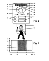
- eine Ausführungsform einer Außenstation der Videotürsprechanlage,
- Fig. 3
- den Gesamt-Erfassungsbereich der Kamera mit "gezoomtem" Bildausschnitt.
- In
Fig. 2 ist eine Ausführungsform einer Außenstation 1 der Videotürsprechanlage dargestellt. Die Außenstation 1 der Türsprechanlage weist auf: - Mindestens eine Türklingel 2,
- Mindestens ein Namensschild 3 hierzu,
- eine Kamera 4
- eine z. B. oberhalb der Kamera 4 angeordnete Temperatursensorzeile 9 (Thermokette, Thermosäule, Thermopile-Zeile) oder Temperatursensormatrix (Temperatursensorarray, Thermopile-Array), bestehend aus mehreren, z. B. fünf Temperatursensoren 8A, 8B, 8C, 8D, 8E (Temperaturmesspunkten),
- eine Personenbeleuchtung 18 zur Beleuchtung des Gesichts der Person vor der Kamera 4, z. B. bestehend aus mehreren LEDs, ggf. Infrarot-LEDs,
- einen Dämmerungssensor 22.
- In
Fig. 3 ist der Gesamt-Erfassungsbereich der Kamera mit "gezoomtem" Bildausschnitt dargestellt. Es ist ein x/y-Koordinatensystem zur Darstellung des Gesamt-Erfassungsbereiches 5 mit seiner Breite x (horizontale Achse) und seiner Höhe y (vertikale Achse) gezeigt: - Für den Gesamt-Erfassungsbereich 5 der Kamera gilt: x1 < x < x4 und y1 <y<y4.
- Für den begrenzten Bildausschnitt 6 gilt: x2 < x < x3 und y1 < y < y4.
- Zur Bildung der x-abhängigen Thermospannung werden die Sensorsignale der einzelnen, den Gesamt-Erfassungsbereich 5 detektierenden Temperaturmesspunkte 8A, 8B, 8C, 8D, 8E ausgewertet, wobei der relevante (begrenzte) Bildausschnitt durch die maximale Thermospannung festgelegt wird. Wie durch die unter
Fig. 2 skizzierte Position einer Person 11 im Zusammenhang mitFig. 3 zum Ausdruck gebracht wird, tritt beim betrachteten Ausführungsbeispiel lediglich im begrenzten Bildausschnitt 6 zwischen x2 und x3 detektierbare Wärmestrahlung auf, so dass die Thermospannung zwischen diesen beiden x-Koordinaten ihr Maximum aufweist. Dementsprechend wird der gezeigte begrenzte Bildausschnitt 6 aus dem gesamten Gesamt-Erfassungsbereich 5 ausgewählt. - Bei Verwendung einer Temperatursensormatrix an Stelle einer Temperatursensorzeile ist es möglich, die Thermospannung nicht nur längs der x-Achse, sondern auch längs der y-Achse zu detektieren, um exakt denjenigen begrenzten Bildausschnitt 6 innerhalb des Gesamt-Erfassungsbereiches 5 der Kamera 4 zu bestimmen, welcher das Gesicht einer zu erfassenden Person 11 zeigt. In gleicher Funktion ist auch der Einsatz der Kombination einer vertikal und einer horizontal eingesetzten Temperatursensorzeile möglich.
- In
Fig. 1 ist ein Ausführungsbeispiel zur elektrischen Verschaltung der wesentlichen Komponenten einer Videotürsprechanlage dargestellt. Die Außenstation 1 weist eine Verarbeitungs- und Steuereinrichtung 12 auf, welche eingangsseitig die Bildsignale der Kamera 4 und die Sensorsignale aller Temperaturmesspunkte 8A, 8B, 8C.... empfängt, hieraus die Thermospannungsverteilung innerhalb des Gesamt-Erfassungsbereiches 5 berechnet und nachfolgend denjenigen begrenzten Bildausschnitt 6 bestimmt, welcher den Bereich der maximalen Wärmestrahlung vor der Kamera repräsentiert. Die von der Kamera 4 erzeugten Bildsignale dieses begrenzten Bildausschnitts 6 werden einer Bildverarbeitungseinrichtung 13 zugeführt, die ausgangsseitig mit einem Buskoppler 14 verbunden ist, welcher an einen Bus (z. B. der Gebäudesystemtechnik) 15 angeschlossen ist. Mittels eines Monitors 16 einer Wohnungsstation kann nunmehr der begrenzte Bildausschnitt 6 dargestellt werden. - Ein ODER-Ausgang 23 der Verarbeitungs- und Steuereinrichtung 12 gibt ein Sensorsignal sL ab, sobald ein Temperatursensor (Temperarturmesspunkt) 8A, 8B, 8C ... eine signifikante Wärmerhöhung vor der Außenstation 1 detektiert. Eine signifikante Wärmeerhöhung bedeutet in diesem Zusammenhang, dass die Wärmeerhöhung hinsichtlich ihrer Intensität typisch für eine sich der Außenstation 1 nähernde Person ist.
- Dieses Sensorsignal sL wird einerseits einer Schaltstufe 17 (z. B. mit einem Transistor gebildet) zur Ansteuerung der Personenbeleuchtung 18 zugeleitet. Vorzugsweise ist die Personen beleuchtung 18 durch mehrere LEDs ausgeführt, wie vorstehend bereits erwähnt. Bei Einsatz von Infrarot-LEDs wird jede Blendung der vor der Außenstation 1 stehenden Person verhindert, selbstverständlich ist die Kamera 4 für einen solchen Fall entsprechend Infrarot-sensibel auszuführen.
- Das Sensorssignal sL wird andererseits einer Schaltschwelle 19 zugeführt, welche eine Einstellvorrichtung zur Sollwertvorgabe von Umgebungslicht aufweist. Der Dämmerungssensor (z. B. Fotowiderstand) 22 liefert der Schaltschwelle 19 ein dem aktuellen Wert des Umgebungslichts entsprechendes Signal. Ausgangsseitig steuert die Schaltschwelle 19 eine Schaltstufe (Laststufe mit Relais oder Halbleiterschalter) 20 an, sobald das mittels des Dämmerungssensors 22 detektierte Umgebungslicht geringer als der durch die Sollwertvorgabe der Schaltschwelle 19 vorgegebene Wert ist. Über die angesteuerte / durchgeschaltete Schaltstufe 20 wird eine netzgespeiste Beleuchtung (230 V-Beleuchtung) 21 zur Beleuchtung des Umgebungsbereichs um die Außenstation 1 der Videotürsprechanlage versorgt.
- Das Ausschalten der Personenbeleuchtung 18 und der netzgespeisten Beleuchtung 21 erfolgt, sobald von den Temperatursensoren 8A, 8B, 8C.... keine durch eine Person hervorgerufene Wärme vor der Außenstation 1 mehr detektiert wird, wobei selbstverständlich eine Ausschaltverzögerung vorgegeben werden kann.
- Die Konfiguration mit Schaltschwelle 19 / Dämmerungssensor 22 ist lediglich optional, d. h. bei einer vereinfachten Ausführungsform der Außenstation 1 ohne Schaltschwelle 19 / Dämmerungssensor 22 wird das Sensorsignal sL direkt der Schaltstufe 20 zugeleitet, d. h. die netzgespeiste Beleuchtung 21 wird in einem solchen Fall nicht erst bei Dämmerung oder bei Nacht, sondern stets bei Auftreten des Sensorsignals sL zugeschaltet.
- In Weiterbildung der Erfindung kann das Sensorsignal sL am ODER-Ausgang 23 der Verarbeitungs- und Steuereinrichtung 12 herangezogen werden, die Kamera 4 einzuschalten. Ferner kann durch das Sensorssignal sL der Aufbau der Kommunikation einschließlich Signalisierung (Türklingel) der Videotürsprechanlage eines Einfamilienhauses gestartet werden. Dies hat den Vorteil, dass am Monitor 16 der Wohnungsstation Personen beobachtet werden können, bevor sie die Türklingel 2 betätigen oder ohne dass sie die Türklingel 2 betätigen.
- Die Energieversorgung der Türstation 1 erfolgt vorzugsweise aus dem Bus 15 respektive bei Nutzung von Ethernet vorzugsweise über "Power over Ethernet". In einem solchen Fall ist ein Trenn-Baustein 24 für Daten und Energie zwischen Buskoppler 14 und Bus 15 eingefügt, welcher über Energieversorgungsleitungen 25 die Kamera 4, die Verarbeitungs- und Steuereinrichtung 12, die Bildverarbeitungseinrichtung 13, den Buskoppler 14, die Schaltstufe 17, die Personenbeleuchtung 18, die Schaltschwelle 19 und den Dämmerungssensor 22 speist.
- Für den Schaltausgang 26 der Schaltstufe 20 zum Anschluss der netzgespeisten Beleuchtung 21 ist ein potentialfreier, vom Bus 15 entsprechend getrennter Schaltkontakt vorgesehen.
-
- 1
- Außenstation einer Videotürsprechanlage
- 2
- Türklingel
- 3
- Namensschild
- 4
- Kamera
- 5
- Gesamt-Erfassungsbereich
- 6
- begrenzter Bildausschnitt
- 7
- ---
- 8
- 8A, 8B, 8C, 8D, 8E... Temperatursensoren (Temperaturmesspunkte)
- 9
- Temperatursensorzeile oder Temperatursensormatrix
- 10
- ---
- 11
- Person
- 12
- Verarbeitungs- und Steuereinrichtung
- 13
- Bildverarbeitungseinrichtung
- 14
- Buskoppler
- 15
- Bus
- 16
- Monitor einer Wohnungsstation
- 17
- Schaltstufe (z. B. Transistor) zur Ansteuerung der Personenbeleuchtung
- 18
- Personenbeleuchtung (z. B. mehrere LEDs)
- 19
- Schaltschwelle für Umgebungslicht mit Einstelleinrichtung für Sollwertvorgabe
- 20
- Schaltstufe (Laststufe mit z. B. Relais)
- 21
- Netzgespeiste Beleuchtung (230 V-Beleuchtung)
- 22
- Dämmerungssensor (z. B. Fotowiderstand) zur Messung des Umgebungslichts
- 23
- ODER-Ausgang
- 24
- Trenn-Baustein für Daten und Energie
- 25
- Energieversorgungsleitungen
- 26
- Schaltausgang
- x
- horizontale Achse = Breite
- x1...
- Koordinaten auf der horizontalen Achse
- y
- vertikale Achse = Höhe
- y1...
- Koordinaten auf der vertikalen Achse
- sL
- Sensorsignal der Verarbeitungs- und Steuereinrichtung
Claims (7)
- Videotürsprechanlage mit einer Außenstation (1), welche Personen mittels einer Kamera (4) erfasst, und mindestens einer mit der Außenstation (1) in Wirkverbindung stehenden Wohnungsstation, wobei die Wärmestrahlung innerhalb des Gesamt-Erfassungsbereiches (5) der Kamera (4) über mehrere als Thermokette oder Thermosäule oder Thermopile-Zeile oder Thermosensorarray oder Thermopile-Array ausgeführte Temperatursensoren (8A, 8B, 8C...) detektiert wird und wobei unter Einsatz einer Signale der Temperatursensoren (8A, 8B, 8C...) empfangenden Verarbeitungs- und Steuereinrichtung (12) der Außenstation (1) aus dem Gesamt-Erfassungsbereich (5) der Kamera (4) ein begrenzter "gezoomter" Bildausschnitt (6) abgeleitet wird, welcher dem Bereich der von den Temperatursensoren (8A, 8B, 8C...) detektierten maximalen Wärmestrahlung folgt, dadurch gekennzeichnet• dass die Verarbeitungs- und Steuereinrichtung (12) ein Sensorsignal (sL) zum Einschalten einer Beleuchtung (18, 21) erzeugt, sobald von mindestens einem Temperatursensor (8A, 8B, 8C...) eine Wärmeerhöhung, welche hinsichtlich ihrer Intensität typisch für eine sich der Außenstation nähernde Person ist, vor der Außenstation (1) detektiert wird,• dass das Sensorsignal (sL) über eine Schaltstufe (17) zur Ansteuerung/Einschaltung einer in der Außenstation (1) integrierten Personenbeleuchtung (18) zur Beleuchtung des Gesichts der Person vor der Kamera (18) zugeleitet wird,• dass das Sensorssignal (sL) einer Schaltschwelle 19 zugeführt wird, welche eine Einstellvorrichtung zur Sollwertvorgabe von Umgebungslicht aufweist, wobei die Schaltschwelle (19) ausgangsseitig eine Schaltstufe (20) ansteuert, und über die angesteuerte / durchgeschaltete Schaltstufe (20) eine netzgespeiste Beleuchtung (21) zur Beleuchtung des Umgebungsbereichs um die Außenstation (1) der Videotürsprechanlage versorgt,• dass die Personenbeleuchtung (18) durch mehrere LEDs gebildet ist,• dass das Sensorsignal (sL) über die Schaltstufe (20) eine externe, netzgespeiste Beleuchtung (21) einschaltet,• dass das Sensorsignal (sL) zum Einschalten der Kamera (4) herangezogen wird,• dass das Sensorsignal (sL) zum Starten des Aufbaus der Kommunikation zwischen Türstation (1) und Wohnungsstation herangezogen wird,• dass die Energieversorgung der Türstation (1) über einen zwischen der Außenstation (1) und der mindestens einen Wohnungsstation vorgesehenen Bus (15) erfolgt, und• dass das Ausschalten der Personenbeleuchtung (18) und der netzgespeisten Beleuchtung (21) erfolgt, sobald von den Temperatursensoren (8A, 8B, 8C....) keine durch eine Person hervorgerufene Wärme vor der Außenstation (1) mehr detektiert wird.
- Videotürsprechanlage nach Anspruch 1, dadurch gekennzeichnet, dass die LEDs der Personenbeleuchtung (18) in Form von Infrarot-LEDs ausgeführt sind.
- Videotürsprechanlage nach Anspruch 1, dadurch gekennzeichnet, dass der Schaltstufe (20) eine mittels eines Dämmerungssensors (22) beaufschlagte Schaltschwelle (19) vorgeschaltet ist.
- Videotürsprechanlage nach Anspruch 1, dass die Außenstation (1) bei Verwendung von "Power over Ethernet" einen Trenn-Baustein (24) für Daten und Energie aufweist.
- Videotürsprechanlage nach einem der vorstehenden Ansprüche, dadurch gekennzeichnet, dass mehrere Temperatursensoren (8A, 8B, 8C...) in Form mindestens einer Zeile angeordnet sind.
- Videotürsprechanlage nach einem der Ansprüche 1 - 4, dadurch gekennzeichnet, dass mehrere Temperatursensoren (8A, 8B, 8C...) in Form einer Matrix angeordnet sind.
- Videotürsprechanlage nach einem der Ansprüche 1 - 4, dadurch gekennzeichnet, dass die Temperatursensoren (8A, 8B, 8C...) in Form einer horizontal und einer vertikal angeordneten Zeile kombiniert sind.
Applications Claiming Priority (1)
| Application Number | Priority Date | Filing Date | Title |
|---|---|---|---|
| DE102008039977A DE102008039977A1 (de) | 2008-08-27 | 2008-08-27 | Videotürsprechanlage mit einer Außenstation, welche Personen mittels einer Kamera erfasst |
Publications (2)
| Publication Number | Publication Date |
|---|---|
| EP2160033A1 EP2160033A1 (de) | 2010-03-03 |
| EP2160033B1 true EP2160033B1 (de) | 2015-09-02 |
Family
ID=41051021
Family Applications (1)
| Application Number | Title | Priority Date | Filing Date |
|---|---|---|---|
| EP09008789.1A Not-in-force EP2160033B1 (de) | 2008-08-27 | 2009-07-04 | Videosprechanlage mit einer Außenstation, welche Personen mittels einer Kamera erfasst |
Country Status (4)
| Country | Link |
|---|---|
| EP (1) | EP2160033B1 (de) |
| CN (1) | CN101662669B (de) |
| DE (1) | DE102008039977A1 (de) |
| ES (1) | ES2548015T3 (de) |
Cited By (1)
| Publication number | Priority date | Publication date | Assignee | Title |
|---|---|---|---|---|
| CN109379571A (zh) * | 2018-12-13 | 2019-02-22 | 移康智能科技(上海)股份有限公司 | 一种智能猫眼的实现方法及智能猫眼 |
Families Citing this family (4)
| Publication number | Priority date | Publication date | Assignee | Title |
|---|---|---|---|---|
| JP5508198B2 (ja) * | 2010-09-01 | 2014-05-28 | パナソニック株式会社 | インターホンシステム |
| DE202011110280U1 (de) * | 2011-12-20 | 2013-04-30 | Telegärtner GmbH | Türsprechanlage |
| CN103519790B (zh) * | 2013-07-09 | 2016-05-18 | 深圳市科瑞电子有限公司 | 基于社区智能化平台的无线体温监测系统及其运行方法 |
| CN104539883A (zh) * | 2014-12-04 | 2015-04-22 | 李理 | 一种多功能可视对讲装置 |
Family Cites Families (8)
| Publication number | Priority date | Publication date | Assignee | Title |
|---|---|---|---|---|
| US5382943A (en) * | 1991-07-31 | 1995-01-17 | Tanaka; Mutuo | Remote monitoring unit |
| US5428388A (en) * | 1992-06-15 | 1995-06-27 | Richard von Bauer | Video doorbell system |
| GB2319712A (en) * | 1996-11-26 | 1998-05-27 | Answermaid Int Ltd | Transmission of video and audio information |
| NL1029960C1 (nl) * | 2005-07-18 | 2006-01-09 | Internova Holding Bvba | Detectie-camera. |
| CN1786422A (zh) * | 2005-11-29 | 2006-06-14 | 李铁顺 | 矿用瓦斯监控方法与系统 |
| US8334906B2 (en) * | 2006-05-24 | 2012-12-18 | Objectvideo, Inc. | Video imagery-based sensor |
| DE102006033133B3 (de) | 2006-07-18 | 2007-09-06 | Abb Patent Gmbh | Einrichtung zur Erfassung von Personen mittels Kamera, insbesondere Videotürsprechanlage |
| CN201322868Y (zh) * | 2008-11-21 | 2009-10-07 | 广西大学 | 智能远程基站监控系统 |
-
2008
- 2008-08-27 DE DE102008039977A patent/DE102008039977A1/de not_active Withdrawn
-
2009
- 2009-04-30 CN CN200910138410.1A patent/CN101662669B/zh not_active Expired - Fee Related
- 2009-07-04 ES ES09008789.1T patent/ES2548015T3/es active Active
- 2009-07-04 EP EP09008789.1A patent/EP2160033B1/de not_active Not-in-force
Cited By (1)
| Publication number | Priority date | Publication date | Assignee | Title |
|---|---|---|---|---|
| CN109379571A (zh) * | 2018-12-13 | 2019-02-22 | 移康智能科技(上海)股份有限公司 | 一种智能猫眼的实现方法及智能猫眼 |
Also Published As
| Publication number | Publication date |
|---|---|
| CN101662669B (zh) | 2014-04-09 |
| EP2160033A1 (de) | 2010-03-03 |
| CN101662669A (zh) | 2010-03-03 |
| DE102008039977A1 (de) | 2010-03-04 |
| ES2548015T3 (es) | 2015-10-13 |
| HK1141916A1 (en) | 2010-11-19 |
Similar Documents
| Publication | Publication Date | Title |
|---|---|---|
| EP2160033A1 (de) | Videosprechanlage mit einer Aussenstation, welche Personen mittels einer Kamera erfasst | |
| DE102007059934A1 (de) | Hauskommunikationssystem mit Türstation | |
| EP1008971B1 (de) | Überwachungssystem, basierend auf einer Hängevorrichtung für elektrisch zu kontaktierende Gegenstände | |
| EP1158840B1 (de) | Fernbedienung von Bewegungs- und/oder Präsenzmeldern | |
| DE69114682T2 (de) | Elektrisches Kontroll- und Steuerungssystem einer Funktionseinheit, insbesondere eines Hauses eines Gebäudes, eines Schiffes oder dergleichen. | |
| DE19724141C2 (de) | Nachtsichtbrille | |
| DE102007041383B4 (de) | Rauch- und Wärmeabzugs- und Lüftungseinrichtung umfassend Rauch- und Wärmeabzugs- und Lüftungsgeräte mit jeweils einem motorischen Antrieb | |
| DE102010024992B4 (de) | Aktor und Energiemanagementsystem mit solchen Aktoren | |
| DE102006033133B3 (de) | Einrichtung zur Erfassung von Personen mittels Kamera, insbesondere Videotürsprechanlage | |
| EP0669786A1 (de) | Sicherheitsbeleuchtung | |
| DE102023119333A1 (de) | Elektrisches installationsgerät | |
| EP3792891B1 (de) | Bewegungsmelder | |
| DE10064534A1 (de) | Anzeigevorrichtung für Fassaden-Displays | |
| DE102010000190B4 (de) | Gebäudeinstallationssystem | |
| AT410723B (de) | Anordnung zum einstellen und bedienen von festinstallierten schaltsignalgebern | |
| DE19624569C2 (de) | Bewegungsmelder mit optimaler Ausleuchtung der Umgebung bei einem einzigen Bewegungssensor und zwei Schaltmitteln | |
| DE102004049819B3 (de) | Lichtansteuervorrichtung | |
| DE102010013553A1 (de) | Steuerung für verstellbare Fassadenelemente | |
| EP3664584B1 (de) | Selbsttätig schaltendes lichtsystem für ein gebäude mit optionaler anbindung an ein lms- bzw. bms-system zu analyse und steuerungs-zwecken | |
| EP2364069B1 (de) | Verfahren zur Steuerung eines Präsenzmelders, und entsprechender Präsenzmelder | |
| EP1575169B1 (de) | Bildverarbeitender Näherungsschalter | |
| DE202008002020U1 (de) | Elektronische Schaltung | |
| DE202014106174U1 (de) | Anordnung zum Betreiben von Leuchtmitteln | |
| DE19730230A1 (de) | Sicherheitseinrichtung | |
| EP2530933A2 (de) | Bildaufzeichnungs- und Abspeicherungsgerät |
Legal Events
| Date | Code | Title | Description |
|---|---|---|---|
| PUAI | Public reference made under article 153(3) epc to a published international application that has entered the european phase |
Free format text: ORIGINAL CODE: 0009012 |
|
| AK | Designated contracting states |
Kind code of ref document: A1 Designated state(s): AT BE BG CH CY CZ DE DK EE ES FI FR GB GR HR HU IE IS IT LI LT LU LV MC MK MT NL NO PL PT RO SE SI SK SM TR |
|
| AX | Request for extension of the european patent |
Extension state: AL BA RS |
|
| 17P | Request for examination filed |
Effective date: 20100330 |
|
| 17Q | First examination report despatched |
Effective date: 20100510 |
|
| GRAP | Despatch of communication of intention to grant a patent |
Free format text: ORIGINAL CODE: EPIDOSNIGR1 |
|
| INTG | Intention to grant announced |
Effective date: 20150515 |
|
| GRAS | Grant fee paid |
Free format text: ORIGINAL CODE: EPIDOSNIGR3 |
|
| GRAA | (expected) grant |
Free format text: ORIGINAL CODE: 0009210 |
|
| AK | Designated contracting states |
Kind code of ref document: B1 Designated state(s): AT BE BG CH CY CZ DE DK EE ES FI FR GB GR HR HU IE IS IT LI LT LU LV MC MK MT NL NO PL PT RO SE SI SK SM TR |
|
| REG | Reference to a national code |
Ref country code: GB Ref legal event code: FG4D Free format text: NOT ENGLISH |
|
| REG | Reference to a national code |
Ref country code: AT Ref legal event code: REF Ref document number: 747251 Country of ref document: AT Kind code of ref document: T Effective date: 20150915 Ref country code: CH Ref legal event code: EP |
|
| REG | Reference to a national code |
Ref country code: IE Ref legal event code: FG4D Free format text: LANGUAGE OF EP DOCUMENT: GERMAN |
|
| REG | Reference to a national code |
Ref country code: ES Ref legal event code: FG2A Ref document number: 2548015 Country of ref document: ES Kind code of ref document: T3 Effective date: 20151013 |
|
| REG | Reference to a national code |
Ref country code: DE Ref legal event code: R096 Ref document number: 502009011487 Country of ref document: DE |
|
| PG25 | Lapsed in a contracting state [announced via postgrant information from national office to epo] |
Ref country code: LT Free format text: LAPSE BECAUSE OF FAILURE TO SUBMIT A TRANSLATION OF THE DESCRIPTION OR TO PAY THE FEE WITHIN THE PRESCRIBED TIME-LIMIT Effective date: 20150902 Ref country code: GR Free format text: LAPSE BECAUSE OF FAILURE TO SUBMIT A TRANSLATION OF THE DESCRIPTION OR TO PAY THE FEE WITHIN THE PRESCRIBED TIME-LIMIT Effective date: 20151203 Ref country code: NO Free format text: LAPSE BECAUSE OF FAILURE TO SUBMIT A TRANSLATION OF THE DESCRIPTION OR TO PAY THE FEE WITHIN THE PRESCRIBED TIME-LIMIT Effective date: 20151202 Ref country code: LV Free format text: LAPSE BECAUSE OF FAILURE TO SUBMIT A TRANSLATION OF THE DESCRIPTION OR TO PAY THE FEE WITHIN THE PRESCRIBED TIME-LIMIT Effective date: 20150902 |
|
| REG | Reference to a national code |
Ref country code: LT Ref legal event code: MG4D Ref country code: NL Ref legal event code: FP |
|
| PG25 | Lapsed in a contracting state [announced via postgrant information from national office to epo] |
Ref country code: PL Free format text: LAPSE BECAUSE OF FAILURE TO SUBMIT A TRANSLATION OF THE DESCRIPTION OR TO PAY THE FEE WITHIN THE PRESCRIBED TIME-LIMIT Effective date: 20150902 Ref country code: SE Free format text: LAPSE BECAUSE OF FAILURE TO SUBMIT A TRANSLATION OF THE DESCRIPTION OR TO PAY THE FEE WITHIN THE PRESCRIBED TIME-LIMIT Effective date: 20150902 |
|
| PG25 | Lapsed in a contracting state [announced via postgrant information from national office to epo] |
Ref country code: EE Free format text: LAPSE BECAUSE OF FAILURE TO SUBMIT A TRANSLATION OF THE DESCRIPTION OR TO PAY THE FEE WITHIN THE PRESCRIBED TIME-LIMIT Effective date: 20150902 Ref country code: SK Free format text: LAPSE BECAUSE OF FAILURE TO SUBMIT A TRANSLATION OF THE DESCRIPTION OR TO PAY THE FEE WITHIN THE PRESCRIBED TIME-LIMIT Effective date: 20150902 Ref country code: IS Free format text: LAPSE BECAUSE OF FAILURE TO SUBMIT A TRANSLATION OF THE DESCRIPTION OR TO PAY THE FEE WITHIN THE PRESCRIBED TIME-LIMIT Effective date: 20160102 |
|
| PG25 | Lapsed in a contracting state [announced via postgrant information from national office to epo] |
Ref country code: RO Free format text: LAPSE BECAUSE OF FAILURE TO SUBMIT A TRANSLATION OF THE DESCRIPTION OR TO PAY THE FEE WITHIN THE PRESCRIBED TIME-LIMIT Effective date: 20150902 Ref country code: PT Free format text: LAPSE BECAUSE OF FAILURE TO SUBMIT A TRANSLATION OF THE DESCRIPTION OR TO PAY THE FEE WITHIN THE PRESCRIBED TIME-LIMIT Effective date: 20160104 |
|
| REG | Reference to a national code |
Ref country code: DE Ref legal event code: R097 Ref document number: 502009011487 Country of ref document: DE |
|
| PLBE | No opposition filed within time limit |
Free format text: ORIGINAL CODE: 0009261 |
|
| STAA | Information on the status of an ep patent application or granted ep patent |
Free format text: STATUS: NO OPPOSITION FILED WITHIN TIME LIMIT |
|
| 26N | No opposition filed |
Effective date: 20160603 |
|
| PG25 | Lapsed in a contracting state [announced via postgrant information from national office to epo] |
Ref country code: DK Free format text: LAPSE BECAUSE OF FAILURE TO SUBMIT A TRANSLATION OF THE DESCRIPTION OR TO PAY THE FEE WITHIN THE PRESCRIBED TIME-LIMIT Effective date: 20150902 Ref country code: SI Free format text: LAPSE BECAUSE OF FAILURE TO SUBMIT A TRANSLATION OF THE DESCRIPTION OR TO PAY THE FEE WITHIN THE PRESCRIBED TIME-LIMIT Effective date: 20150902 |
|
| PGFP | Annual fee paid to national office [announced via postgrant information from national office to epo] |
Ref country code: DE Payment date: 20160722 Year of fee payment: 8 |
|
| PG25 | Lapsed in a contracting state [announced via postgrant information from national office to epo] |
Ref country code: BE Free format text: LAPSE BECAUSE OF NON-PAYMENT OF DUE FEES Effective date: 20160731 |
|
| PGFP | Annual fee paid to national office [announced via postgrant information from national office to epo] |
Ref country code: ES Payment date: 20160715 Year of fee payment: 8 |
|
| REG | Reference to a national code |
Ref country code: CH Ref legal event code: PL |
|
| GBPC | Gb: european patent ceased through non-payment of renewal fee |
Effective date: 20160704 |
|
| PG25 | Lapsed in a contracting state [announced via postgrant information from national office to epo] |
Ref country code: MC Free format text: LAPSE BECAUSE OF FAILURE TO SUBMIT A TRANSLATION OF THE DESCRIPTION OR TO PAY THE FEE WITHIN THE PRESCRIBED TIME-LIMIT Effective date: 20150902 |
|
| PG25 | Lapsed in a contracting state [announced via postgrant information from national office to epo] |
Ref country code: CH Free format text: LAPSE BECAUSE OF NON-PAYMENT OF DUE FEES Effective date: 20160731 Ref country code: FR Free format text: LAPSE BECAUSE OF NON-PAYMENT OF DUE FEES Effective date: 20160801 Ref country code: LI Free format text: LAPSE BECAUSE OF NON-PAYMENT OF DUE FEES Effective date: 20160731 |
|
| REG | Reference to a national code |
Ref country code: FR Ref legal event code: ST Effective date: 20170331 |
|
| REG | Reference to a national code |
Ref country code: IE Ref legal event code: MM4A |
|
| PG25 | Lapsed in a contracting state [announced via postgrant information from national office to epo] |
Ref country code: GB Free format text: LAPSE BECAUSE OF NON-PAYMENT OF DUE FEES Effective date: 20160704 |
|
| PG25 | Lapsed in a contracting state [announced via postgrant information from national office to epo] |
Ref country code: IE Free format text: LAPSE BECAUSE OF NON-PAYMENT OF DUE FEES Effective date: 20160704 |
|
| PG25 | Lapsed in a contracting state [announced via postgrant information from national office to epo] |
Ref country code: LU Free format text: LAPSE BECAUSE OF NON-PAYMENT OF DUE FEES Effective date: 20160704 |
|
| PGFP | Annual fee paid to national office [announced via postgrant information from national office to epo] |
Ref country code: NL Payment date: 20170719 Year of fee payment: 9 |
|
| PGFP | Annual fee paid to national office [announced via postgrant information from national office to epo] |
Ref country code: IT Payment date: 20170728 Year of fee payment: 9 Ref country code: FI Payment date: 20170720 Year of fee payment: 9 Ref country code: CZ Payment date: 20170630 Year of fee payment: 9 |
|
| PGFP | Annual fee paid to national office [announced via postgrant information from national office to epo] |
Ref country code: AT Payment date: 20170720 Year of fee payment: 9 |
|
| REG | Reference to a national code |
Ref country code: DE Ref legal event code: R119 Ref document number: 502009011487 Country of ref document: DE |
|
| PG25 | Lapsed in a contracting state [announced via postgrant information from national office to epo] |
Ref country code: DE Free format text: LAPSE BECAUSE OF NON-PAYMENT OF DUE FEES Effective date: 20180201 |
|
| PG25 | Lapsed in a contracting state [announced via postgrant information from national office to epo] |
Ref country code: CY Free format text: LAPSE BECAUSE OF FAILURE TO SUBMIT A TRANSLATION OF THE DESCRIPTION OR TO PAY THE FEE WITHIN THE PRESCRIBED TIME-LIMIT Effective date: 20150902 Ref country code: SM Free format text: LAPSE BECAUSE OF FAILURE TO SUBMIT A TRANSLATION OF THE DESCRIPTION OR TO PAY THE FEE WITHIN THE PRESCRIBED TIME-LIMIT Effective date: 20150902 Ref country code: HU Free format text: LAPSE BECAUSE OF FAILURE TO SUBMIT A TRANSLATION OF THE DESCRIPTION OR TO PAY THE FEE WITHIN THE PRESCRIBED TIME-LIMIT; INVALID AB INITIO Effective date: 20090704 |
|
| PG25 | Lapsed in a contracting state [announced via postgrant information from national office to epo] |
Ref country code: HR Free format text: LAPSE BECAUSE OF FAILURE TO SUBMIT A TRANSLATION OF THE DESCRIPTION OR TO PAY THE FEE WITHIN THE PRESCRIBED TIME-LIMIT Effective date: 20150902 Ref country code: MT Free format text: LAPSE BECAUSE OF FAILURE TO SUBMIT A TRANSLATION OF THE DESCRIPTION OR TO PAY THE FEE WITHIN THE PRESCRIBED TIME-LIMIT Effective date: 20150902 Ref country code: TR Free format text: LAPSE BECAUSE OF FAILURE TO SUBMIT A TRANSLATION OF THE DESCRIPTION OR TO PAY THE FEE WITHIN THE PRESCRIBED TIME-LIMIT Effective date: 20150902 Ref country code: MK Free format text: LAPSE BECAUSE OF FAILURE TO SUBMIT A TRANSLATION OF THE DESCRIPTION OR TO PAY THE FEE WITHIN THE PRESCRIBED TIME-LIMIT Effective date: 20150902 |
|
| PG25 | Lapsed in a contracting state [announced via postgrant information from national office to epo] |
Ref country code: BG Free format text: LAPSE BECAUSE OF FAILURE TO SUBMIT A TRANSLATION OF THE DESCRIPTION OR TO PAY THE FEE WITHIN THE PRESCRIBED TIME-LIMIT Effective date: 20150902 |
|
| REG | Reference to a national code |
Ref country code: ES Ref legal event code: FD2A Effective date: 20181106 |
|
| PG25 | Lapsed in a contracting state [announced via postgrant information from national office to epo] |
Ref country code: CZ Free format text: LAPSE BECAUSE OF NON-PAYMENT OF DUE FEES Effective date: 20180704 |
|
| PG25 | Lapsed in a contracting state [announced via postgrant information from national office to epo] |
Ref country code: ES Free format text: LAPSE BECAUSE OF NON-PAYMENT OF DUE FEES Effective date: 20170705 |
|
| REG | Reference to a national code |
Ref country code: NL Ref legal event code: MM Effective date: 20180801 |
|
| REG | Reference to a national code |
Ref country code: AT Ref legal event code: MM01 Ref document number: 747251 Country of ref document: AT Kind code of ref document: T Effective date: 20180704 |
|
| PG25 | Lapsed in a contracting state [announced via postgrant information from national office to epo] |
Ref country code: FI Free format text: LAPSE BECAUSE OF NON-PAYMENT OF DUE FEES Effective date: 20180704 Ref country code: AT Free format text: LAPSE BECAUSE OF NON-PAYMENT OF DUE FEES Effective date: 20180704 |
|
| PG25 | Lapsed in a contracting state [announced via postgrant information from national office to epo] |
Ref country code: NL Free format text: LAPSE BECAUSE OF NON-PAYMENT OF DUE FEES Effective date: 20180801 |
|
| PG25 | Lapsed in a contracting state [announced via postgrant information from national office to epo] |
Ref country code: IT Free format text: LAPSE BECAUSE OF NON-PAYMENT OF DUE FEES Effective date: 20180704 |