EP3664584B1 - Selbsttätig schaltendes lichtsystem für ein gebäude mit optionaler anbindung an ein lms- bzw. bms-system zu analyse und steuerungs-zwecken - Google Patents
Selbsttätig schaltendes lichtsystem für ein gebäude mit optionaler anbindung an ein lms- bzw. bms-system zu analyse und steuerungs-zwecken Download PDFInfo
- Publication number
- EP3664584B1 EP3664584B1 EP19214055.6A EP19214055A EP3664584B1 EP 3664584 B1 EP3664584 B1 EP 3664584B1 EP 19214055 A EP19214055 A EP 19214055A EP 3664584 B1 EP3664584 B1 EP 3664584B1
- Authority
- EP
- European Patent Office
- Prior art keywords
- contactor
- lighting system
- sensor
- lights
- person
- Prior art date
- Legal status (The legal status is an assumption and is not a legal conclusion. Google has not performed a legal analysis and makes no representation as to the accuracy of the status listed.)
- Active
Links
Images

Classifications
-
- H—ELECTRICITY
- H05—ELECTRIC TECHNIQUES NOT OTHERWISE PROVIDED FOR
- H05B—ELECTRIC HEATING; ELECTRIC LIGHT SOURCES NOT OTHERWISE PROVIDED FOR; CIRCUIT ARRANGEMENTS FOR ELECTRIC LIGHT SOURCES, IN GENERAL
- H05B47/00—Circuit arrangements for operating light sources in general, i.e. where the type of light source is not relevant
- H05B47/10—Controlling the light source
- H05B47/175—Controlling the light source by remote control
- H05B47/19—Controlling the light source by remote control via wireless transmission
-
- H—ELECTRICITY
- H05—ELECTRIC TECHNIQUES NOT OTHERWISE PROVIDED FOR
- H05B—ELECTRIC HEATING; ELECTRIC LIGHT SOURCES NOT OTHERWISE PROVIDED FOR; CIRCUIT ARRANGEMENTS FOR ELECTRIC LIGHT SOURCES, IN GENERAL
- H05B47/00—Circuit arrangements for operating light sources in general, i.e. where the type of light source is not relevant
- H05B47/10—Controlling the light source
- H05B47/105—Controlling the light source in response to determined parameters
- H05B47/115—Controlling the light source in response to determined parameters by determining the presence or movement of objects or living beings
- H05B47/13—Controlling the light source in response to determined parameters by determining the presence or movement of objects or living beings by using passive infrared detectors
-
- H—ELECTRICITY
- H05—ELECTRIC TECHNIQUES NOT OTHERWISE PROVIDED FOR
- H05B—ELECTRIC HEATING; ELECTRIC LIGHT SOURCES NOT OTHERWISE PROVIDED FOR; CIRCUIT ARRANGEMENTS FOR ELECTRIC LIGHT SOURCES, IN GENERAL
- H05B47/00—Circuit arrangements for operating light sources in general, i.e. where the type of light source is not relevant
- H05B47/10—Controlling the light source
- H05B47/105—Controlling the light source in response to determined parameters
- H05B47/115—Controlling the light source in response to determined parameters by determining the presence or movement of objects or living beings
-
- Y—GENERAL TAGGING OF NEW TECHNOLOGICAL DEVELOPMENTS; GENERAL TAGGING OF CROSS-SECTIONAL TECHNOLOGIES SPANNING OVER SEVERAL SECTIONS OF THE IPC; TECHNICAL SUBJECTS COVERED BY FORMER USPC CROSS-REFERENCE ART COLLECTIONS [XRACs] AND DIGESTS
- Y02—TECHNOLOGIES OR APPLICATIONS FOR MITIGATION OR ADAPTATION AGAINST CLIMATE CHANGE
- Y02B—CLIMATE CHANGE MITIGATION TECHNOLOGIES RELATED TO BUILDINGS, e.g. HOUSING, HOUSE APPLIANCES OR RELATED END-USER APPLICATIONS
- Y02B20/00—Energy efficient lighting technologies, e.g. halogen lamps or gas discharge lamps
- Y02B20/40—Control techniques providing energy savings, e.g. smart controller or presence detection
Definitions
- the present invention relates to an automatically switching light system for a building and a method for refurbishing an existing light system
- SE 529 781 C2 relates to a lighting arrangement according to the preamble of claim 1.
- WO 2017/139707 A1 relates to a system for changing the light level of one or more lamps connected to a control device such as a timer or a lighting panel using only conventional relays or lighting panels.
- U.S. 2016/323958 A1 describes a DCR capable illuminant that responds to various digital control signals from various digital control means.
- JP H08 227609 A describes a heat radiation-sensing, automatic switch device that detects the entry of a person into a room and controls a lamp.
- a contactor is used (load side) due to the high switching loads of the lights.
- the people sensors activate the contactor coil (control side). This avoids that the internal relay of the person sensors is overloaded.
- the contactor is installed in the central sub-distribution. Additional cables and wires must be installed between the sub-distribution board and the lighting system in order to control the lights based on movement.
- the object of the present invention is to provide a lighting system that can be implemented more simply.
- the object is achieved by a lighting system according to claim 1 and a method for refurbishing an existing lighting system for a building with a large number of lights and a sub-distribution according to claim 11.
- a special feature of the lighting system according to the present invention is that the contactor is arranged in a supply line from the lighting system to a sub-distribution board of the building. This has the advantage that the lighting system can be switched based on the person sensor without having to change the sub-distribution. Furthermore, the amount of cabling can be reduced, since cables from people sensors to the contactor do not have to be routed to the sub-distribution board.
- the lighting system can be designed for the interior, for the area near the building or for the exterior.
- the light system can be designed with a connection to an LMS or BMS system for analysis and control purposes.
- a sub-distribution is the first distribution point in the building after the house connection box or a meter connection column.
- the sub-distribution can also be referred to as a low-voltage sub-distribution (NSUV or NUV).
- NSUV low-voltage sub-distribution
- the sub-distribution is preferably located in the basement or in a service room.
- One or more electricity meters and, if necessary, ripple control receivers can be installed in the sub-distribution.
- the size of the sub-distributions (meter space) are regulated according to DIN 18012, DIN 18013 (house connection niches) and VDE-AR-N 4101 (design); the number of meters is important in residential buildings.
- the sub-distribution can be connected to the load contactor via an at least 5-pin cable.
- three-phase current can be used here.
- the contactor preferably switches at least three poles.
- the lighting system is supplied with power via a further, preferably separately supplied, power supply.
- the separate power supply can be used, for example, for emergency power lights and for operating electronics.
- the contactor is preferably arranged outside a distribution box of the sub-distribution, in particular at a distance of at least five meters from the distribution box.
- the contactor preferably only switches the power supply for the primary lamps of the lighting system.
- Electronic circuits of the lighting system in particular the person sensor, are preferably also supplied with power via a further power supply when the contactor switches off.
- a cable with at least 7 poles can be used, with five poles supplying the three-phase current and two poles being intended for the supply of the secondary power source.
- the secondary power supply has more than two poles.
- the lighting system can be equipped with a bus system, in which case the bus system can also be designed to provide a certain low power for supplying electronic circuits.
- the person sensor and/or the contactor is connected by radio to a controller which is designed to activate the contactor.
- the load contacts of the contactor then turn the lights ON or OFF.
- the person sensor is connected wirelessly to an LMS/BMS system or a controller, with the controller, the LMS/BMS system or the controller being designed to activate the contactor.
- the LMS/BMS system or the controller is preferably arranged centrally in the building.
- the contactor can be controlled either via the LMS/BMS system, the control directly via the internal programmed Function/logic or movement-dependent via the corresponding movement sensors in the field. This has the advantage that no connecting cable needs to be laid between the contactor/sensor and the LMS/BMS or control system.
- the contactor switches at least three phases.
- it can be a three-phase connection switched by the contactor.
- the lighting system includes a mains feed terminal, with the contactor being arranged in the supply line between the sub-distribution and the mains feed terminal close to the lights or in/on the mains feed terminal of the lights, i.e. in particular within 50 cm or preferably within of 20cm from the luminaire or the mains feed terminal.
- the mains feed terminal can preferably have terminals for all five poles of a three-phase power supply strip. Additional feed terminals can be provided, which supply the lighting system with an additional circuit, e.g. a low-power circuit. Electronics or, if necessary, lights in emergency exit signs can be supplied with power via the low-power circuit.
- additional circuit e.g. a low-power circuit. Electronics or, if necessary, lights in emergency exit signs can be supplied with power via the low-power circuit.
- the multiplicity of lights is arranged as a light band.
- it can be light bands for shelving cabinets.
- the multiplicity of lights is designed as light inserts for a mounting rail system and/or the person sensor is arranged on the mounting rail system.
- the person sensor is a movement sensor, in particular a passive infrared sensor, an HF sensor, a lidar sensor and/or a camera sensor etc.
- a movement sensor in particular a passive infrared sensor, an HF sensor, a lidar sensor and/or a camera sensor etc.
- a large number of such motion sensors can be provided.
- the lighting system also includes a memory for recording the switching operations of the contactor.
- the memory can be located in the LMS/BMS system or connected to the controller.
- the memory can, for example, record the time, date and type of switching process (e.g. on/off), switch-on time and forward it to the higher-level LMS/BMS system or the controller for further analysis. From this, for example, profiles of energy consumption or traffic can be determined. This means that the sensor and switching data can also be analyzed and evaluated afterwards.
- the control unit can be designed to provide analysis and evaluation functions.
- the system also includes at least one temperature sensor and/or at least one light sensor, with the system being designed to transmit measured temperature values from the at least one temperature sensor and/or measured light values from the at least one light sensor, in particular via radio transfer to a central unit.
- the radio connections are therefore preferably designed in such a way that a central control unit can both receive measurement data from the sensors and send control data to the contactor, e.g. for switching the contactor on or off.
- the contactor has an integrated temperature sensor that has a temperature of the contactor measures.
- the measured temperatures can be transmitted wirelessly to the central unit. If a certain temperature threshold is exceeded, the central unit can trigger an alarm.
- the central unit comprises an analysis unit which is designed to analyze the sensor data.
- the sensor data can be recorded, analyzed and evaluated centrally.
- a decision about a switching operation of the contactor can then be made by a control logic.
- control logic can be designed to switch on the contactor only when both the person sensor detects a person and the light sensor measures that the ambient brightness is lower than a predetermined threshold value.
- the contactor is designed to switch at least 1 kW, preferably at least 10 kW.
- the contactor is installed in the supply line between a mains feed terminal of the lighting system and the sub-distribution board.
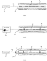
- the light system 10 shown has a multiplicity of lamp inserts 12 which are arranged in a mounting rail system 2 .
- the lighting system 10 is connected to the sub-distribution board 16 via a supply line 14 .
- the light system 20 shown includes, in addition to the light inserts 22, motion sensors 26.
- the light system 20 is connected to the sub-distribution board 28 via a supply line 24.
- the sub-distribution 28 includes a contactor 29.
- the supply line 24 is at least a 7-pin cable. 5 poles are intended for the supply of three-phase current and 2 poles for the connection of the movement sensors 26 to the sub-distribution.
- the light system 30 shown comprises a multiplicity of lamp inserts 32 which are arranged as a light strip. Furthermore, the light system 30 includes motion sensors 36, which in particular can detect a movement of a person.
- the movement sensors 36 are preferably designed and arranged in such a way that they detect the movement of a person in front of the mounting rail system 2 .
- the movement sensors 36 are connected via a cable to electronics (not shown in figure 3 ) tied together. Depending on a signal from the sensors, the electronics switch the contactor 33, which is arranged in the supply line 34 from the lighting system 30 to the sub-distribution board 38.
- the lighting system 30 is connected to the supply line 34 via a mains feed terminal 37 , which connects the lighting system 30 to the sub-distribution board 38 .
- the contactor 33 is arranged behind the mains feed terminal 37, i.e. between the mains feed terminal 37 and the sub-distribution board 38.
- FIG figure 4 shows a lighting system 40 according to the invention with a plurality of lights 42. Similar to that in FIG figure 3 In the light system 30 shown, the plurality of lights 42 is connected via a mains feed terminal 47 and a contactor 43 in a supply line 44 to a sub-distribution board 48 .
- the contactor 43 is connected via a preferably bidirectional radio link 51 to a central control unit 50, for example a control unit of a building management system or a light management system.
- a central control unit 50 for example a control unit of a building management system or a light management system.
- the person sensors 46 are connected to the control unit 50 via a bidirectional radio link 51 .
- the person sensors 46 can transmit information about the presence of a person to the control unit 50 .
- the radio links 51 are preferably at least bi-directional in the sense that the sensors can send data and the contactor can receive data from a central unit.
- the contactor can also send a temperature value (e.g. ambient temperature) to the central unit.
- the temperature values are required, for example, to prevent overloading of the contactor, e.g. B. to analyze because of too high ambient temperature or overload due to too many connected switching loads or because of contact aging and to generate warnings / error messages. Data are thus sent and received to the central unit.
- the control unit then contains a control logic that decides when the contactor 43 should be switched.
- the control logic can not only take into account the presence of people measured by the person sensors, but also a time of day.
- the data from the sensors and the switching processes can be recorded in the control unit 50 .
- the measurement data and switching processes, ambient temperatures (temperature sensor in the contactor or motion sensor) and daylight and/or artificial light in the building (light sensor in the contactor or motion sensor) can be saved together with the time and date in a project file, which is stored in be implemented in a blockchain so that later modification of the recorded data can be ruled out.
- the data collected and stored in this way can be used for further analysis.
- the control unit preferably provides an interface with which the data of the blockchain can be read out.
Landscapes
- Engineering & Computer Science (AREA)
- Computer Networks & Wireless Communication (AREA)
- Circuit Arrangement For Electric Light Sources In General (AREA)
Description
- Die vorliegende Erfindung betrifft ein selbsttätig schaltendes Lichtsystem für ein Gebäude und ein Verfahren zum Sanieren eines Bestands-Lichtsystems
-
SE 529 781 C2 -
WO 2017/139707 A1 betrifft ein System zum Ändern des Lichtniveaus von eines oder mehrerer Leuchtkörper, die mit einer Steuervorrichtung, wie einem Timer oder einem Beleuchtungspaneel, verbunden sind, unter Verwendung ausschließlich konventioneller Relais oder Leuchtpaneele. -
US 2016/323958 A1 beschreibt einen DCR-fähigen Leuchtkörper, der auf verschiedene digitale Kontrollsignale von unterschiedlichen digitalen Steuermitteln reagiert. -
JP H08 227609 A - Sollen bei der Sanierung eines Lichtsystems die Leuchten in einem Bereich abhängig von der Anwesenheit einer Person gesteuert werden, wird aufgrund der hohen Schaltlasten der Leuchten ein Schütz verwendet (Lastseite). Die Personen-Sensoren steuern die Schützspule an (Steuerseite). Somit wird vermieden, dass das innenliegende Relais der Personensensoren überlastet wird. Das Schütz wird dabei in der zentralen Unterverteilung montiert. Zwischen Unterverteilung und Lichtsystem müssen zusätzliche Kabel und Leitungen montiert werden, um die Leuchten bewegungsabhängig zu steuern.
- Aufgabe der vorliegenden Erfindung ist es, ein Lichtsystem bereitzustellen, das einfacher realisiert werden kann.
- Gelöst wird die Aufgabe durch ein Lichtsystem nach Anspruch 1 und ein Verfahren zum Sanieren eines Bestands-Lichtsystems für ein Gebäude mit einer Vielzahl von Leuchten und einer Unterverteilung gemäß Anspruch 11.
- Insbesondere wird hierzu ein selbsttätig schaltendes Lichtsystem für ein Gebäude bereitgestellt, umfassend:
- eine Vielzahl von Leuchten,
- einen Personen-Sensor zum Detektieren einer Person und
- ein durch den Personen-Sensor geschalteten Schütz zum Schalten wenigstens einer Teilgruppe der Vielzahl von Leuchten des Lichtsystems.
- Eine Besonderheit des Lichtsystems gemäß der vorliegenden Erfindung besteht darin, dass der Schütz in einer Zuleitung vom Lichtsystem zu einer Unterverteilung des Gebäudes angeordnet ist. Dies hat den Vorteil, dass das Lichtsystem basierend auf dem Personen-Sensor geschaltet werden kann, ohne die Unterverteilung verändern zu müssen. Weiterhin kann ein Verkabelungsaufwand reduziert werden, da Kabel von Personen-Sensoren zum Schütz nicht bis zur Unterverteilung geführt werden müssen.
- Das Lichtsystem kann für den Innenbereich, für den gebäudenahen Bereich oder für den Außenbereich ausgebildet sein. Das Lichtsystem kann mit einer Anbindung an ein LMS- oder BMS-System zur Analyse und Steuerungszwecken ausgebildet sein.
- Eine Unterverteilung ist nach dem Hausanschlusskasten oder einer Zähleranschlusssäule die erste Aufteilungsstelle im Gebäude. Die Unterverteilung kann auch als Niederspannungsunterverteilung (NSUV oder NUV) bezeichnet werden. Die Unterverteilung befindet sich vorzugsweise im Keller oder in einem Hausanschlussraum. In der Unterverteilung können ein oder mehrere Stromzähler und gegebenenfalls Rundsteuerempfänger eingebaut sein kann. Die Größe der Unterverteilungen (Zählerplatz) sind nach DIN 18012, DIN 18013 (Hausanschlussnischen) sowie der VDE-AR-N 4101 (Ausführung) geregelt, dabei ist in Wohnhäusern die Anzahl der Zähler von Bedeutung.
- Stromversorgungssysteme müssen bei Neuinstallationen gemäß der TAB 2007 sowie der DIN 18015-1 als Strahlennetze ausgeführt werden. In kleinen Gebäuden ist die Unterverteilung häufig die einzige Verteilung, wobei bei Vorhandensein mehrerer Stockwerke/Ebenen (z. B. Keller, Erdgeschoss, Obergeschoss) eine Errichtung von Unterverteilungen je Etage vorgeschrieben ist (DIN 18015-2). Unterverteilungen können weitere NSUV einspeisen. In größeren Gebäuden und Industriebetrieben sind in der Regel zusätzliche Unterverteilungen und Gruppenverteilungen vorhanden.
- Vorzugsweise kann die Unterverteilung mit dem Lastschütz über ein zumindest 5-poliges Kabel verbunden sein. Insbesondere kann hierbei Drehstrom zum Einsatz kommen. Vorzugsweise schaltet der Schütz dabei zumindest drei Pole.
- Außer der Leistungsversorgung über den Drehstrom kann vorgesehen sein, dass das Lichtsystem über eine weitere, vorzugsweise separat zugeführte, Stromversorgung mit Strom versorgt wird. Die separate Stromversorgung kann z.B. für Notstromleuchten und zum Betrieb von Elektronik verwendet werden.
- Vorzugsweise wird der Schütz außerhalb eines Verteilerkastens der Unterverteilung angeordnet, insbesondere mit einem Abstand von zumindest fünf Metern entfernt von dem Verteilerkasten.
- Vorzugsweise schaltet das Schütz nur die Leistungszuführung für die primären Leuchten des Leuchtsystems. Elektronische Schaltungen des Lichtsystems, insbesondere der Personen-Sensor, werden vorzugsweise über eine weitere Stromversorgung auch dann mit Strom versorgt, wenn der Schütz abschaltet. Hierzu kann z.B. ein mindestens 7-poliges Kabel zum Einsatz kommen, wobei fünf Pole den Drehstrom liefern und zwei Pole für die Versorgung mit der sekundären Stromquelle vorgesehen sind. In anderen Ausführungsformen weist die sekundäre Stromversorgung mehr als zwei Pole auf.
- Das Lichtsystem kann mit einem Bus-System ausgestattet sein, wobei das Bus-System auch dazu ausgebildet sein kann, eine gewisse geringe Leistung zur Versorgung von elektronischen Schaltungen bereitzustellen.
- In einer erfindungsgemäßen Ausführungsform ist vorgesehen, dass der Personen-Sensor und/oder der Schütz über Funk mit einer Steuerung verbunden ist, die dazu ausgebildet ist, den Schütz anzusteuern. Die Lastkontakte des Schützes schalten dann die Leuchten EIN oder AUS.
- In einer weiteren bevorzugten Ausführungsform ist vorgesehen, dass der Personen-Sensor einem LMS/BMS-System oder einer Steuerung drahtlos verbunden ist, wobei die Steuerung das LMS/BMS-System oder die Steuerung dazu ausgebildet ist, den Schütz anzusteuern. Vorzugsweise ist das LMS/BMS-System oder die Steuerung zentral in dem Gebäude angeordnet. Die Ansteuerung des Schützes kann entweder über das LMS/BMS-System, die Steuerung direkt über die interne programmierte Funktion/Logik oder bewegungsabhängig über die entsprechenden Bewegungs-Sensoren im Feld erfolgen. Dies hat den Vorteil, dass keine Verbindungsleitung zwischen Schütz/Sensor und dem LMS/BMS- oder Steuerungssystem zu verlegen ist.
- In einer weiteren bevorzugten Ausführungsform ist vorgesehen, dass der Schütz zumindest drei Phasen schaltet. Insbesondere kann es sich um eine durch den Schütz geschaltete Drehstromanbindung handeln.
- In einer bevorzugten Ausführungsform ist vorgesehen, dass das Lichtsystem eine Netzeinspeiseklemme umfasst, wobei der Schütz in der Zuleitung zwischen der Unterverteilung und der Netzeinspeiseklemme nah an den Leuchten bzw. in/an der Netzeinspeiseklemme der Leuchten angeordnet ist, d.h. insbesondere innerhalb von 50cm oder vorzugsweise innerhalb von 20cm von der Leuchte oder der Netzeinspeiseklemme.
- Die Netzeinspeiseklemme kann vorzugsweise Klemmen für alle fünf Pole einer Drehstromversorgungsleiste aufweisen. Es können weitere Einspeiseklemmen vorgesehen sein, die das Lichtsystem mit einem weiteren Stromkreis versorgt, z.B. einem Niederleistungs-Stromkreis. Über den Niederleistungs-Stromkreis können Elektronik oder ggf. auch Leuchten in Notausgangsschildern mit Strom versorgt werden.
- In einer weiteren bevorzugten Ausführungsform ist vorgesehen, dass die Vielzahl von Leuchten als Lichtband angeordnet ist. Insbesondere kann es sich um Lichtbänder für Regalschränke handeln.
- In einer weiteren bevorzugten Ausführungsform ist vorgesehen, dass die Vielzahl von Leuchten als Leuchteneinsätze für ein Tragschienensystem ausgebildet ist und/oder der Personen-Sensor auf dem Tragschienensystem angeordnet ist.
- In einer weiteren bevorzugten Ausführungsform ist vorgesehen, dass der Personen-Sensor ein Bewegungssensor, insbesondere ein Passiv-Infrarot-Sensor, ein HF-Sensor, ein Lidar-Sensor und/oder ein Kamera-Sensor etc. ist. Insbesondere kann eine Vielzahl von derartigen Bewegungssensoren vorgesehen sein.
- In einer weiteren bevorzugten Ausführungsform umfasst das Lichtsystem weiterhin einen Speicher zur Erfassung der Schaltvorgänge des Schützes. Der Speicher kann zum Beispiel im LMS/BMS-System oder mit der Steuerung verbunden angeordnet sein. Der Speicher kann z.B. Uhrzeit, Datum und Art des Schaltvorgangs (z.B. An/Aus), Einschaltzeit erfassen und an das übergeordnete LMS/BMS-System oder der Steuerung zur weiteren Analyse weiter leiten. Daraus können zum Beispiel Profile über Energieverbrauch oder Frequentierung ermittelt werden. Somit kann auch im Nachhinein eine Analyse und Auswertung der Sensor- und Schaltdaten erfolgen. Insbesondere kann die Steuereinheit dazu ausgebildet sein, Analyse- und Auswertungsfunktionen bereitzustellen.
- In einer weiteren Ausführungsform ist vorgesehen, dass das System weiterhin zumindest einen Temperatursensor und/oder zumindest einen Lichtsensor umfasst, wobei das System dazu ausgebildet ist, Temperaturmesswerte von dem zumindest einen Temperatursensor und/oder Lichtmesswerte von dem zumindest einen Lichtsensor, insbesondere über Funk, an eine zentrale Einheit zu übertragen. Die Funkverbindungen sind also vorzugsweise so ausgebildet, dass eine zentrale Steuereinheit sowohl Messdaten von den Sensoren empfangen kann, als auch Steuerdaten, z.B. zum Ein- oder Ausschalten des Schützes, an den Schütz senden kann.
- Insbesondere kann vorgesehen sein, dass der Schütz einen integrierten Temperatursensor aufweist, der eine Temperatur des Schützes misst. Die gemessenen Temperaturen können per Funk an die zentrale Einheit übertragen werden. Bei Überschreiten eines bestimmten Temperaturschwellwerts kann die zentrale Einheit einen Alarm auslösen.
- In einer weiteren Ausführungsform ist vorgesehen, dass die zentrale Einheit eine Analyseeinheit umfasst, die dazu ausgebildet ist, die Sensordaten zu analysieren. Somit können die Sensordaten zentral erfasst, analysiert und ausgewertet werden. Abhängig von der Auswertung kann dann von einer Steuerlogik eine Entscheidung über einen Schaltvorgang des Schützes getroffen werden.
- Zum Beispiel kann die Steuerlogik dazu ausgebildet sein, den Schütz nur dann einzuschalten, wenn sowohl der Personen-Sensor eine Person detektiert als auch der Lichtsensor misst, dass die Umgebungshelligkeit geringer als ein vorgegebener Schwellwert ist.
- In einer weiteren bevorzugten Ausführungsform ist vorgesehen, dass der Schütz dazu ausgebildet ist mindestens 1kW, vorzugsweise mindestens 10kW, zu schalten.
- Ein weiterer Aspekt der Erfindung bezieht sich auf ein Verfahren zum Sanieren eines Bestands-Lichtsystems für ein Gebäude mit einer Vielzahl von Leuchten, wobei das Verfahren umfasst:
- Einbauen eines Personen-Sensors zum Detektieren einer Person in das Bestands-Lichtsystem,
- Einbauen eines durch den Personen-Sensor geschalteten Schütz zum Schalten wenigstens einer Teilgruppe der Vielzahl von Leuchten des Bestands-Lichtsystems in einer Zuleitung zwischen der Unterverteilung des Gebäudes und der Vielzahl von Leuchten des Bestands-Lichtsystems, und
- Verbinden des Personen-Sensors und/oder des Schütz über Funk mit einer Steuerung, die dazu ausgebildet ist, den Schütz anzusteuern.
- In einer weiteren bevorzugten Ausführungsform ist vorgesehen, dass der Schütz in die Zuleitung zwischen einer Netzeinspeiseklemme des Lichtsystems und der Unterverteilung eingebaut wird.
- Weitere Merkmale und Vorteile der vorliegenden Erfindung werden aus der nachfolgenden detaillierten Beschreibung einer Ausführungsform deutlich, welche in Bezug auf die beigefügte Figur gegeben wird.
-
Figur 1 zeigt ein Lichtsystem aus dem Stand der Technik; -
Figur 2 zeigt ein weiteres Lichtsystem aus dem Stand der Technik; und -
Figur 3 zeigt ein weiteres Lichtsystem, welches zum Verständnis der Erfindung hilfreich ist. -
Figur 4 ein erfindungsgemäßes Lichtsystem. - Das in
Figur 1 gezeigten Lichtsystem 10 weist eine Vielzahl von Leuchteneinsätzen 12 auf, die in einem Tragschienensystem 2 angeordnet sind. Über eine Zuleitung 14 ist das Lichtsystem 10 mit der Unterverteilung 16 verbunden. - Das in
Figur 2 gezeigte Lichtsystem 20 umfasst neben den Leuchteneinsätzen 22 weiterhin Bewegungs-Sensoren 26. Das Lichtsystem 20 wird über eine Zuleitung 24 mit der Unterverteilung 28 verbunden. Die Unterverteilung 28 umfasst dabei einen Schütz 29. Die Zuleitung 24 ist ein mindestens 7-poliges Kabel. Dabei sind 5 Pole für die Versorgung mit Drehstrom bestimmt und 2 Pole für die Verbindung der Bewegungs-Sensoren 26 mit der Unterverteilung. - Das in
Figur 3 gezeigte Lichtsystem 30 umfasst eine Vielzahl von Leuchteneinsätzen 32, die als Leuchtband angeordnet sind. Weiterhin umfasst das Lichtsystem 30 Bewegungs-Sensoren 36, die insbesondere eine Bewegung von einer Person erfassen können. Vorzugsweise sind die Bewegungs-Sensoren 36 dabei so ausgebildet und angeordnet, dass sie die Bewegung einer Person vor dem Tragschienensystem 2 erfassen. Die Bewegungs-Sensoren 36 sind dabei über ein Kabel mit einer Elektronik (nicht dargestellt inFigur 3 ) verbunden. Die Elektronik schaltet abhängig von einem Signal der Sensoren das Schütz 33, das in der Zuleitung 34 von dem Lichtsystem 30 zur Unterverteilung 38 angeordnet ist. - Das Lichtsystem 30 wird über eine Netzeinspeiseklemme 37 mit der Zuleitung 34 verbunden, die das Lichtsystem 30 mit der Unterverteilung 38 verbindet. Das Schütz 33 ist dabei aus Sicht des Lichtsystems hinter der Netzeinspeiseklemme 37 angeordnet, d.h. zwischen Netzeinspeiseklemme 37 und Unterverteilung 38.
-
Figur 4 zeigt ein erfindungsgemäßes Lichtsystem 40 mit einer Vielzahl von Leuchten 42. Ähnlich wie bei dem inFigur 3 gezeigten Lichtsystem 30 ist die Vielzahl von Leuchten 42 über eine Netzeinspeiseklemme 47, und einen Schütz 43 in einer Zuleitung 44 mit einer Unterverteilung 48 verbunden. - Bei dem Lichtsystem 40 der
Figur 4 ist der Schütz 43 über eine, vorzugsweise bidirektionale, Funkverbindung 51 mit einer zentralen Steuereinheit 50, z.B. einer Steuereinheit eines Building-Management-Systems oder eines Light-Management-Systems, verbunden. Ebenso die die Personen-Sensoren 46 über eine bidirektionale Funkverbindung 51 mit der Steuereinheit 50 verbunden. Somit können die Personen-Sensoren 46 Informationen über die Anwesenheit einer Person an die Steuereinheit 50 übertragen. - Die Funkverbindungen 51 sind vorzugsweise zumindest bidirektional in dem Sinne, dass die Sensoren Daten senden können und der Schütz Daten von einer zentralen Einheit empfangen kann. Der Schütz kann aber auch einen Temperaturwert (z.B. Umgebungstemperatur) an die zentrale Einheit schicken. Die Temperaturwerte werden benötigt um zum Beispiel eine Überlastung des Schützes z. B. wegen zu hoher Umgebungstemperatur oder Überlastung durch zu viel angeschlossene Schaltlasten oder wegen Kontakt-Alterung zu analysieren und daraus Warnmeldungen/Fehlermeldungen zu erzeugen. Es werden also zu der zentralen Einheit Daten gesendet und empfangen.
- Die Steuereinheit beinhaltet dann eine Steuerungslogik, die entscheidet, wann der Schütz 43 geschaltet werden soll. Zum Beispiel kann die Steuerlogik dabei nicht nur die durch die Personen-Sensoren gemessene Anwesenheit von Personen berücksichtigen, sondern auch eine Tageszeit. Weiterhin kann in der Steuereinheit 50 eine Aufzeichnung der Daten von den Sensoren und der Schaltvorgänge erfolgen. Insbesondere können die Messdaten und Schaltvorgänge, Umgebungstemperaturen (Temperatursensor in Schütz oder Bewegungs-Sensor) und Tageslicht- und/oder Kunstlichteintrag im Gebäude (LichtSensor in Schütz oder Bewegungs-Sensor) zusammen mit Uhrzeit und Datum in einer Projekt-Datei gespeichert werden, welche in einem Blockchain realisiert werden so dass eine spätere Modifikation der aufgezeichneten Daten ausgeschlossen werden kann. Die so erhobenen und gespeicherten Daten können für weitere Analysen verwendet werden. Vorzugsweise stellt Steuereinheit dazu eine Schnittstelle, mit der die Daten der Blockchain ausgelesen werden können.
-
- 10
- Lichtsystem
- 12
- Leuchteneinsätze
- 14
- Zuleitung
- 16
- Unterverteilung
- 20
- Lichtsystem
- 22
- Leuchteneinsätze
- 24
- Zuleitung
- 26
- Bewegungs-Sensoren
- 28
- Unterverteilung
- 30
- Lichtsystem
- 32
- Leuchteneinsätze
- 34
- Zuleitung
- 36
- Bewegungs-Sensoren
- 37
- Netzeinspeiseklemme
- 38
- Unterverteilung
- 39
- Schütz
- 40
- Lichtsystem
- 42
- Vielzahl von Leuchten
- 43
- Schütz
- 44
- Zuleitung
- 46
- Personen-Sensor
- 47
- Netzeinspeiseklemme
- 48
- Unterverteilung
- 50
- Zentrale Steuereinheit
- 51
- Funkverbindung
Claims (12)
- Selbsttätig schaltendes Lichtsystem (40) für ein Gebäude, umfassend:- eine Vielzahl von Leuchten (42),- einen Personen-Sensor (46) zum Detektieren einer Person,- einen durch den Personen-Sensor (46) geschalteten Schütz (43) zum Schalten wenigstens einer Teilgruppe der Vielzahl von Leuchten des Lichtsystems (40), und- eine Steuerung (50), die dazu ausgebildet ist, den Schütz (43) anzusteuern,wobei der Personen-Sensor (46) und/oder der Schütz (43) über Funk (51) mit der Steuerung (50) verbunden ist,
dadurch gekennzeichnet, dass der Schütz (43) zur Anordnung in einer Zuleitung (44) zwischen einer Unterverteilung (48) des Gebäudes und der Vielzahl von Leuchten (42) des Lichtsystems eingerichtet ist. - Lichtsystem (40) nach Anspruch 1, wobei der Schütz (43) zumindest drei Phasen einer Drehstromanbindung schaltet.
- Lichtsystem (40) nach Anspruch 1, weiterhin umfassend eine Netzeinspeiseklemme (47), wobei die Vielzahl von Leuchten (42) über die Netzeinspeiseklemme (47) verbunden ist und wobei der Schütz (43) in der Zuleitung zwischen der Unterverteilung (48) und der Netzeinspeiseklemme (47) anordenbar ist.
- Lichtsystem (40) nach einem der vorherigen Ansprüche, wobei die Vielzahl von Leuchten (42) als Lichtband angeordnet ist.
- Lichtsystem (40) nach einem der vorherigen Ansprüche, wobei die Vielzahl von Leuchten (42) als Leuchteneinsätze für ein Tragschienensystem ausgebildet ist.
- Lichtsystem (40) nach Anspruch 5, wobei der Personen-Sensor (46) auf dem Tragschienensystem angeordnet ist.
- Lichtsystem (40) nach einem der vorherigen Ansprüche, wobei der Personen-Sensor (46) ein Bewegungssensor, insbesondere ein Passiv-Infrarot-Sensor, ist.
- Lichtsystem (40) nach einem der vorherigen Ansprüche, weiterhin umfassend einen Speicher, eingerichtet zur Erfassung der Schaltvorgänge des Schützes (43) und zum Weiterleiten an ein übergeordnetes LMS/BMS-System oder die Steuerung.
- Lichtsystem (40) nach einem der vorherigen Ansprüche, wobei das System weiterhin zumindest einen Temperatursensor und/oder zumindest einen Lichtsensor umfasst, wobei das System dazu ausgebildet ist, Temperaturmesswerte von dem zumindest einen Temperatursensor und/oder Lichtmesswerte von dem zumindest einen Lichtsensor, insbesondere über Funk, an eine zentrale Einheit zu übertragen.
- Lichtsystem (40) nach einem der vorherigen Ansprüche, wobei der Schütz (43) dazu ausgebildet ist mindestens 1kW, vorzugsweise mindestens 10kW, zu schalten.
- Verfahren zum Sanieren eines Bestands-Lichtsystems (40) für ein Gebäude mit einer Vielzahl von Leuchten (42) und einer Unterverteilung (48), wobei das Verfahren umfasst:- Einbauen eines Personen-Sensors (46) zum Detektieren einer Person in das Bestands-Lichtsystem,- Einbauen eines durch den Personen-Sensor geschalteten Schütz (43) zum Schalten wenigstens einer Teilgruppe der Vielzahl von Leuchten des Bestands-Lichtsystems in einer Zuleitung zwischen der Unterverteilung des Gebäudes und der Vielzahl von Leuchten des Bestands-Lichtsystems,- Verbinden des Personen-Sensors (46) und/oder des Schütz (43) über Funk (51) mit einer Steuerung (50), die dazu ausgebildet ist, den Schütz (43) anzusteuern.
- Verfahren nach Anspruch 11, wobei der Schütz (43) in die Zuleitung zwischen einer Netzeinspeiseklemme (47) des Bestands-Lichtsystems (40) und der Unterverteilung (48) eingebaut wird und wobei die Vielzahl von Leuchten (42) mit der Netzeinspeiseklemme (47) verbunden wird.
Applications Claiming Priority (2)
| Application Number | Priority Date | Filing Date | Title |
|---|---|---|---|
| DE102018009603 | 2018-12-06 | ||
| DE102019105206.8A DE102019105206A1 (de) | 2018-12-06 | 2019-03-01 | Selbsttätig schaltendes Lichtsystem für ein Gebäude mit optionaler Anbindung an ein LMS- bzw. BMS-System zu Analyse- und Steuerungs-Zwecken |
Publications (2)
| Publication Number | Publication Date |
|---|---|
| EP3664584A1 EP3664584A1 (de) | 2020-06-10 |
| EP3664584B1 true EP3664584B1 (de) | 2023-01-25 |
Family
ID=68808128
Family Applications (1)
| Application Number | Title | Priority Date | Filing Date |
|---|---|---|---|
| EP19214055.6A Active EP3664584B1 (de) | 2018-12-06 | 2019-12-06 | Selbsttätig schaltendes lichtsystem für ein gebäude mit optionaler anbindung an ein lms- bzw. bms-system zu analyse und steuerungs-zwecken |
Country Status (1)
| Country | Link |
|---|---|
| EP (1) | EP3664584B1 (de) |
Family Cites Families (6)
| Publication number | Priority date | Publication date | Assignee | Title |
|---|---|---|---|---|
| JP2854825B2 (ja) * | 1995-11-30 | 1999-02-10 | 松下電工株式会社 | 人感スイッチ装置 |
| SE529781C2 (sv) * | 2006-01-25 | 2007-11-20 | Auralight Int Ab | Närvarosensorarmatur |
| DE102012202148A1 (de) * | 2012-02-13 | 2013-08-14 | Trilux Gmbh & Co. Kg | Lichtbandsystem |
| CA2867898C (en) * | 2012-03-19 | 2023-02-14 | Digital Lumens Incorporated | Methods, systems, and apparatus for providing variable illumination |
| AT14699U1 (de) * | 2014-10-30 | 2016-04-15 | Tridonic Gmbh & Co Kg | Verfahren zur Ansteuerung für ein Betriebsgerät für Leuchtmittel |
| WO2017139707A1 (en) * | 2016-02-10 | 2017-08-17 | Powerline Control Systems, Inc. | Timer light level setting system and process |
-
2019
- 2019-12-06 EP EP19214055.6A patent/EP3664584B1/de active Active
Also Published As
| Publication number | Publication date |
|---|---|
| EP3664584A1 (de) | 2020-06-10 |
Similar Documents
| Publication | Publication Date | Title |
|---|---|---|
| EP1258957B1 (de) | Schaltgerätesystem | |
| DE102014108657A1 (de) | Schutzschaltgerät | |
| US10965111B2 (en) | Load center | |
| EP2375526A2 (de) | Elektrische Niederspannungsgebäudeinstallation | |
| EP2849019A1 (de) | Verfahren und Steuergerät zum Begrenzen einer elektrischen Belastung in einem Netzzweig eines elektrischen Netzes | |
| EP3189382B1 (de) | Verfahren zur datenerhebung für die konfiguration eines gebäudeautomationssystems und verfahren zum konfigurieren eines gebäudeautomationssystems | |
| US7745959B2 (en) | Integrated lighting control panel with analog inputs/outputs | |
| DE19611161A1 (de) | Schaltungsanordnung zum programmgesteuerten Überwachen und/oder Steuern einer Sicherheitsbeleuchtungsanlage | |
| EP3664584B1 (de) | Selbsttätig schaltendes lichtsystem für ein gebäude mit optionaler anbindung an ein lms- bzw. bms-system zu analyse und steuerungs-zwecken | |
| EP1712110A1 (de) | Einrichtung zur automatisierung der gebäudetechnik | |
| DE102011053616B4 (de) | Verfahren und Vorrichtung zur Überwachung kritischer Temperaturentwicklungen an Solaranlagen mit Photovoltaik-Modulen und Funktionsmodul für eine solche Vorrichtung | |
| DE102019105206A1 (de) | Selbsttätig schaltendes Lichtsystem für ein Gebäude mit optionaler Anbindung an ein LMS- bzw. BMS-System zu Analyse- und Steuerungs-Zwecken | |
| WO2012004019A1 (de) | Ladesäule zum laden einer fahrzeugbatterie | |
| DE102007041383A1 (de) | Rauch- und Wärmeabzugs- und/oder Lüftungseinrichtung umfassend Rauch- und Wärmeabzugsgeräte mit motorischen Antrieben | |
| EP0982642B1 (de) | Verfahren zur Steuerung von Elektro-Installationen in Gebäuden und eine Steuerungsanordnung für die Steuerung von Elektro-Installationen in Gebäuden | |
| DE19832535A1 (de) | Einrichtung zur Regelung und Überwachung von Weichenheizungen | |
| DE102017011373A1 (de) | Mess- und Steuerelektronik für Niederspannungsschaltanlagen | |
| EP2953420A1 (de) | Elektrospeicherheizanlage | |
| DE3122109C2 (de) | ||
| CA2276727A1 (en) | Circuit for selective power supply to electrical units | |
| EP2299340A1 (de) | Zentrale, System und Verfahren zur Steuerung von Funktionseinrichtungen in Gebäuden | |
| AT412691B (de) | System zur steuerung von räumlich verteilten elektrischen verbrauchern in gebäuden | |
| DE102017105196A1 (de) | Steuerungsmodul zur Steuerung elektrischer Geräte | |
| EP4592612B1 (de) | Unterputzwärmepumpensteuerungsgerät sowie anordnung mit einer wärmepumpe und verfahren zur inbetriebnahme einer solchen anordnung | |
| EP3268755B1 (de) | System zur ermittlung des energieverbrauchs eines einzelnen verbrauchers |
Legal Events
| Date | Code | Title | Description |
|---|---|---|---|
| PUAI | Public reference made under article 153(3) epc to a published international application that has entered the european phase |
Free format text: ORIGINAL CODE: 0009012 |
|
| STAA | Information on the status of an ep patent application or granted ep patent |
Free format text: STATUS: THE APPLICATION HAS BEEN PUBLISHED |
|
| AK | Designated contracting states |
Kind code of ref document: A1 Designated state(s): AL AT BE BG CH CY CZ DE DK EE ES FI FR GB GR HR HU IE IS IT LI LT LU LV MC MK MT NL NO PL PT RO RS SE SI SK SM TR |
|
| AX | Request for extension of the european patent |
Extension state: BA ME |
|
| STAA | Information on the status of an ep patent application or granted ep patent |
Free format text: STATUS: REQUEST FOR EXAMINATION WAS MADE |
|
| 17P | Request for examination filed |
Effective date: 20201209 |
|
| RBV | Designated contracting states (corrected) |
Designated state(s): AL AT BE BG CH CY CZ DE DK EE ES FI FR GB GR HR HU IE IS IT LI LT LU LV MC MK MT NL NO PL PT RO RS SE SI SK SM TR |
|
| STAA | Information on the status of an ep patent application or granted ep patent |
Free format text: STATUS: EXAMINATION IS IN PROGRESS |
|
| 17Q | First examination report despatched |
Effective date: 20210604 |
|
| REG | Reference to a national code |
Ref country code: DE Ref legal event code: R079 Ref document number: 502019006867 Country of ref document: DE Free format text: PREVIOUS MAIN CLASS: H05B0047115000 Ipc: H05B0047130000 |
|
| GRAP | Despatch of communication of intention to grant a patent |
Free format text: ORIGINAL CODE: EPIDOSNIGR1 |
|
| STAA | Information on the status of an ep patent application or granted ep patent |
Free format text: STATUS: GRANT OF PATENT IS INTENDED |
|
| RIC1 | Information provided on ipc code assigned before grant |
Ipc: H05B 47/19 20200101ALI20220707BHEP Ipc: H05B 47/13 20200101AFI20220707BHEP |
|
| INTG | Intention to grant announced |
Effective date: 20220804 |
|
| GRAS | Grant fee paid |
Free format text: ORIGINAL CODE: EPIDOSNIGR3 |
|
| GRAA | (expected) grant |
Free format text: ORIGINAL CODE: 0009210 |
|
| STAA | Information on the status of an ep patent application or granted ep patent |
Free format text: STATUS: THE PATENT HAS BEEN GRANTED |
|
| AK | Designated contracting states |
Kind code of ref document: B1 Designated state(s): AL AT BE BG CH CY CZ DE DK EE ES FI FR GB GR HR HU IE IS IT LI LT LU LV MC MK MT NL NO PL PT RO RS SE SI SK SM TR |
|
| REG | Reference to a national code |
Ref country code: GB Ref legal event code: FG4D Free format text: NOT ENGLISH |
|
| REG | Reference to a national code |
Ref country code: CH Ref legal event code: EP |
|
| REG | Reference to a national code |
Ref country code: DE Ref legal event code: R096 Ref document number: 502019006867 Country of ref document: DE |
|
| REG | Reference to a national code |
Ref country code: AT Ref legal event code: REF Ref document number: 1546664 Country of ref document: AT Kind code of ref document: T Effective date: 20230215 Ref country code: IE Ref legal event code: FG4D Free format text: LANGUAGE OF EP DOCUMENT: GERMAN |
|
| REG | Reference to a national code |
Ref country code: NO Ref legal event code: T2 Effective date: 20230125 |
|
| REG | Reference to a national code |
Ref country code: SE Ref legal event code: TRGR |
|
| REG | Reference to a national code |
Ref country code: LT Ref legal event code: MG9D |
|
| REG | Reference to a national code |
Ref country code: NL Ref legal event code: MP Effective date: 20230125 |
|
| PG25 | Lapsed in a contracting state [announced via postgrant information from national office to epo] |
Ref country code: NL Free format text: LAPSE BECAUSE OF FAILURE TO SUBMIT A TRANSLATION OF THE DESCRIPTION OR TO PAY THE FEE WITHIN THE PRESCRIBED TIME-LIMIT Effective date: 20230125 |
|
| PG25 | Lapsed in a contracting state [announced via postgrant information from national office to epo] |
Ref country code: RS Free format text: LAPSE BECAUSE OF FAILURE TO SUBMIT A TRANSLATION OF THE DESCRIPTION OR TO PAY THE FEE WITHIN THE PRESCRIBED TIME-LIMIT Effective date: 20230125 Ref country code: PT Free format text: LAPSE BECAUSE OF FAILURE TO SUBMIT A TRANSLATION OF THE DESCRIPTION OR TO PAY THE FEE WITHIN THE PRESCRIBED TIME-LIMIT Effective date: 20230525 Ref country code: LV Free format text: LAPSE BECAUSE OF FAILURE TO SUBMIT A TRANSLATION OF THE DESCRIPTION OR TO PAY THE FEE WITHIN THE PRESCRIBED TIME-LIMIT Effective date: 20230125 Ref country code: LT Free format text: LAPSE BECAUSE OF FAILURE TO SUBMIT A TRANSLATION OF THE DESCRIPTION OR TO PAY THE FEE WITHIN THE PRESCRIBED TIME-LIMIT Effective date: 20230125 Ref country code: HR Free format text: LAPSE BECAUSE OF FAILURE TO SUBMIT A TRANSLATION OF THE DESCRIPTION OR TO PAY THE FEE WITHIN THE PRESCRIBED TIME-LIMIT Effective date: 20230125 Ref country code: ES Free format text: LAPSE BECAUSE OF FAILURE TO SUBMIT A TRANSLATION OF THE DESCRIPTION OR TO PAY THE FEE WITHIN THE PRESCRIBED TIME-LIMIT Effective date: 20230125 |
|
| PG25 | Lapsed in a contracting state [announced via postgrant information from national office to epo] |
Ref country code: PL Free format text: LAPSE BECAUSE OF FAILURE TO SUBMIT A TRANSLATION OF THE DESCRIPTION OR TO PAY THE FEE WITHIN THE PRESCRIBED TIME-LIMIT Effective date: 20230125 Ref country code: IS Free format text: LAPSE BECAUSE OF FAILURE TO SUBMIT A TRANSLATION OF THE DESCRIPTION OR TO PAY THE FEE WITHIN THE PRESCRIBED TIME-LIMIT Effective date: 20230525 Ref country code: GR Free format text: LAPSE BECAUSE OF FAILURE TO SUBMIT A TRANSLATION OF THE DESCRIPTION OR TO PAY THE FEE WITHIN THE PRESCRIBED TIME-LIMIT Effective date: 20230426 Ref country code: FI Free format text: LAPSE BECAUSE OF FAILURE TO SUBMIT A TRANSLATION OF THE DESCRIPTION OR TO PAY THE FEE WITHIN THE PRESCRIBED TIME-LIMIT Effective date: 20230125 |
|
| REG | Reference to a national code |
Ref country code: DE Ref legal event code: R097 Ref document number: 502019006867 Country of ref document: DE |
|
| PG25 | Lapsed in a contracting state [announced via postgrant information from national office to epo] |
Ref country code: SM Free format text: LAPSE BECAUSE OF FAILURE TO SUBMIT A TRANSLATION OF THE DESCRIPTION OR TO PAY THE FEE WITHIN THE PRESCRIBED TIME-LIMIT Effective date: 20230125 Ref country code: RO Free format text: LAPSE BECAUSE OF FAILURE TO SUBMIT A TRANSLATION OF THE DESCRIPTION OR TO PAY THE FEE WITHIN THE PRESCRIBED TIME-LIMIT Effective date: 20230125 Ref country code: EE Free format text: LAPSE BECAUSE OF FAILURE TO SUBMIT A TRANSLATION OF THE DESCRIPTION OR TO PAY THE FEE WITHIN THE PRESCRIBED TIME-LIMIT Effective date: 20230125 Ref country code: DK Free format text: LAPSE BECAUSE OF FAILURE TO SUBMIT A TRANSLATION OF THE DESCRIPTION OR TO PAY THE FEE WITHIN THE PRESCRIBED TIME-LIMIT Effective date: 20230125 Ref country code: CZ Free format text: LAPSE BECAUSE OF FAILURE TO SUBMIT A TRANSLATION OF THE DESCRIPTION OR TO PAY THE FEE WITHIN THE PRESCRIBED TIME-LIMIT Effective date: 20230125 |
|
| PG25 | Lapsed in a contracting state [announced via postgrant information from national office to epo] |
Ref country code: SK Free format text: LAPSE BECAUSE OF FAILURE TO SUBMIT A TRANSLATION OF THE DESCRIPTION OR TO PAY THE FEE WITHIN THE PRESCRIBED TIME-LIMIT Effective date: 20230125 |
|
| PLBE | No opposition filed within time limit |
Free format text: ORIGINAL CODE: 0009261 |
|
| STAA | Information on the status of an ep patent application or granted ep patent |
Free format text: STATUS: NO OPPOSITION FILED WITHIN TIME LIMIT |
|
| 26N | No opposition filed |
Effective date: 20231026 |
|
| PG25 | Lapsed in a contracting state [announced via postgrant information from national office to epo] |
Ref country code: SI Free format text: LAPSE BECAUSE OF FAILURE TO SUBMIT A TRANSLATION OF THE DESCRIPTION OR TO PAY THE FEE WITHIN THE PRESCRIBED TIME-LIMIT Effective date: 20230125 |
|
| PG25 | Lapsed in a contracting state [announced via postgrant information from national office to epo] |
Ref country code: IT Free format text: LAPSE BECAUSE OF FAILURE TO SUBMIT A TRANSLATION OF THE DESCRIPTION OR TO PAY THE FEE WITHIN THE PRESCRIBED TIME-LIMIT Effective date: 20230125 |
|
| PG25 | Lapsed in a contracting state [announced via postgrant information from national office to epo] |
Ref country code: LU Free format text: LAPSE BECAUSE OF NON-PAYMENT OF DUE FEES Effective date: 20231206 |
|
| PG25 | Lapsed in a contracting state [announced via postgrant information from national office to epo] |
Ref country code: MC Free format text: LAPSE BECAUSE OF FAILURE TO SUBMIT A TRANSLATION OF THE DESCRIPTION OR TO PAY THE FEE WITHIN THE PRESCRIBED TIME-LIMIT Effective date: 20230125 |
|
| REG | Reference to a national code |
Ref country code: BE Ref legal event code: MM Effective date: 20231231 |
|
| PG25 | Lapsed in a contracting state [announced via postgrant information from national office to epo] |
Ref country code: MC Free format text: LAPSE BECAUSE OF FAILURE TO SUBMIT A TRANSLATION OF THE DESCRIPTION OR TO PAY THE FEE WITHIN THE PRESCRIBED TIME-LIMIT Effective date: 20230125 Ref country code: LU Free format text: LAPSE BECAUSE OF NON-PAYMENT OF DUE FEES Effective date: 20231206 |
|
| REG | Reference to a national code |
Ref country code: IE Ref legal event code: MM4A |
|
| PG25 | Lapsed in a contracting state [announced via postgrant information from national office to epo] |
Ref country code: IE Free format text: LAPSE BECAUSE OF NON-PAYMENT OF DUE FEES Effective date: 20231206 |
|
| PG25 | Lapsed in a contracting state [announced via postgrant information from national office to epo] |
Ref country code: BE Free format text: LAPSE BECAUSE OF NON-PAYMENT OF DUE FEES Effective date: 20231231 |
|
| PG25 | Lapsed in a contracting state [announced via postgrant information from national office to epo] |
Ref country code: IE Free format text: LAPSE BECAUSE OF NON-PAYMENT OF DUE FEES Effective date: 20231206 Ref country code: BE Free format text: LAPSE BECAUSE OF NON-PAYMENT OF DUE FEES Effective date: 20231231 |
|
| PG25 | Lapsed in a contracting state [announced via postgrant information from national office to epo] |
Ref country code: BG Free format text: LAPSE BECAUSE OF FAILURE TO SUBMIT A TRANSLATION OF THE DESCRIPTION OR TO PAY THE FEE WITHIN THE PRESCRIBED TIME-LIMIT Effective date: 20230125 |
|
| PG25 | Lapsed in a contracting state [announced via postgrant information from national office to epo] |
Ref country code: BG Free format text: LAPSE BECAUSE OF FAILURE TO SUBMIT A TRANSLATION OF THE DESCRIPTION OR TO PAY THE FEE WITHIN THE PRESCRIBED TIME-LIMIT Effective date: 20230125 |
|
| PGFP | Annual fee paid to national office [announced via postgrant information from national office to epo] |
Ref country code: DE Payment date: 20241216 Year of fee payment: 6 |
|
| PGFP | Annual fee paid to national office [announced via postgrant information from national office to epo] |
Ref country code: CH Payment date: 20250101 Year of fee payment: 6 |
|
| PG25 | Lapsed in a contracting state [announced via postgrant information from national office to epo] |
Ref country code: CY Free format text: LAPSE BECAUSE OF FAILURE TO SUBMIT A TRANSLATION OF THE DESCRIPTION OR TO PAY THE FEE WITHIN THE PRESCRIBED TIME-LIMIT; INVALID AB INITIO Effective date: 20191206 |
|
| PG25 | Lapsed in a contracting state [announced via postgrant information from national office to epo] |
Ref country code: HU Free format text: LAPSE BECAUSE OF FAILURE TO SUBMIT A TRANSLATION OF THE DESCRIPTION OR TO PAY THE FEE WITHIN THE PRESCRIBED TIME-LIMIT; INVALID AB INITIO Effective date: 20191206 |
|
| PG25 | Lapsed in a contracting state [announced via postgrant information from national office to epo] |
Ref country code: TR Free format text: LAPSE BECAUSE OF FAILURE TO SUBMIT A TRANSLATION OF THE DESCRIPTION OR TO PAY THE FEE WITHIN THE PRESCRIBED TIME-LIMIT Effective date: 20230125 |
|
| REG | Reference to a national code |
Ref country code: CH Ref legal event code: U11 Free format text: ST27 STATUS EVENT CODE: U-0-0-U10-U11 (AS PROVIDED BY THE NATIONAL OFFICE) Effective date: 20260101 |
|
| PGFP | Annual fee paid to national office [announced via postgrant information from national office to epo] |
Ref country code: GB Payment date: 20251218 Year of fee payment: 7 |
|
| PGFP | Annual fee paid to national office [announced via postgrant information from national office to epo] |
Ref country code: NO Payment date: 20251216 Year of fee payment: 7 |
|
| PGFP | Annual fee paid to national office [announced via postgrant information from national office to epo] |
Ref country code: AT Payment date: 20251215 Year of fee payment: 7 |
|
| PGFP | Annual fee paid to national office [announced via postgrant information from national office to epo] |
Ref country code: FR Payment date: 20251217 Year of fee payment: 7 |
|
| PGFP | Annual fee paid to national office [announced via postgrant information from national office to epo] |
Ref country code: SE Payment date: 20251217 Year of fee payment: 7 |