EP2159551A2 - Configurable gauge apparatus including a flat panel display and a mechanical pointer - Google Patents
Configurable gauge apparatus including a flat panel display and a mechanical pointer Download PDFInfo
- Publication number
- EP2159551A2 EP2159551A2 EP09168215A EP09168215A EP2159551A2 EP 2159551 A2 EP2159551 A2 EP 2159551A2 EP 09168215 A EP09168215 A EP 09168215A EP 09168215 A EP09168215 A EP 09168215A EP 2159551 A2 EP2159551 A2 EP 2159551A2
- Authority
- EP
- European Patent Office
- Prior art keywords
- stem
- pointer
- flat panel
- panel display
- hub
- Prior art date
- Legal status (The legal status is an assumption and is not a legal conclusion. Google has not performed a legal analysis and makes no representation as to the accuracy of the status listed.)
- Granted
Links
Images


Classifications
-
- G—PHYSICS
- G01—MEASURING; TESTING
- G01D—MEASURING NOT SPECIALLY ADAPTED FOR A SPECIFIC VARIABLE; ARRANGEMENTS FOR MEASURING TWO OR MORE VARIABLES NOT COVERED IN A SINGLE OTHER SUBCLASS; TARIFF METERING APPARATUS; MEASURING OR TESTING NOT OTHERWISE PROVIDED FOR
- G01D13/00—Component parts of indicators for measuring arrangements not specially adapted for a specific variable
- G01D13/02—Scales; Dials
- G01D13/04—Construction
-
- B—PERFORMING OPERATIONS; TRANSPORTING
- B60—VEHICLES IN GENERAL
- B60K—ARRANGEMENT OR MOUNTING OF PROPULSION UNITS OR OF TRANSMISSIONS IN VEHICLES; ARRANGEMENT OR MOUNTING OF PLURAL DIVERSE PRIME-MOVERS IN VEHICLES; AUXILIARY DRIVES FOR VEHICLES; INSTRUMENTATION OR DASHBOARDS FOR VEHICLES; ARRANGEMENTS IN CONNECTION WITH COOLING, AIR INTAKE, GAS EXHAUST OR FUEL SUPPLY OF PROPULSION UNITS IN VEHICLES
- B60K35/00—Instruments specially adapted for vehicles; Arrangement of instruments in or on vehicles
- B60K35/60—Instruments characterised by their location or relative disposition in or on vehicles
-
- G—PHYSICS
- G01—MEASURING; TESTING
- G01D—MEASURING NOT SPECIALLY ADAPTED FOR A SPECIFIC VARIABLE; ARRANGEMENTS FOR MEASURING TWO OR MORE VARIABLES NOT COVERED IN A SINGLE OTHER SUBCLASS; TARIFF METERING APPARATUS; MEASURING OR TESTING NOT OTHERWISE PROVIDED FOR
- G01D11/00—Component parts of measuring arrangements not specially adapted for a specific variable
- G01D11/28—Structurally-combined illuminating devices
-
- B—PERFORMING OPERATIONS; TRANSPORTING
- B60—VEHICLES IN GENERAL
- B60K—ARRANGEMENT OR MOUNTING OF PROPULSION UNITS OR OF TRANSMISSIONS IN VEHICLES; ARRANGEMENT OR MOUNTING OF PLURAL DIVERSE PRIME-MOVERS IN VEHICLES; AUXILIARY DRIVES FOR VEHICLES; INSTRUMENTATION OR DASHBOARDS FOR VEHICLES; ARRANGEMENTS IN CONNECTION WITH COOLING, AIR INTAKE, GAS EXHAUST OR FUEL SUPPLY OF PROPULSION UNITS IN VEHICLES
- B60K2360/00—Indexing scheme associated with groups B60K35/00 or B60K37/00 relating to details of instruments or dashboards
- B60K2360/60—Structural details of dashboards or instruments
- B60K2360/68—Features of instruments
- B60K2360/698—Pointers of combined instruments
- B60K2360/6985—Pointers of combined instruments with only part of pointer being visible
-
- Y—GENERAL TAGGING OF NEW TECHNOLOGICAL DEVELOPMENTS; GENERAL TAGGING OF CROSS-SECTIONAL TECHNOLOGIES SPANNING OVER SEVERAL SECTIONS OF THE IPC; TECHNICAL SUBJECTS COVERED BY FORMER USPC CROSS-REFERENCE ART COLLECTIONS [XRACs] AND DIGESTS
- Y10—TECHNICAL SUBJECTS COVERED BY FORMER USPC
- Y10S—TECHNICAL SUBJECTS COVERED BY FORMER USPC CROSS-REFERENCE ART COLLECTIONS [XRACs] AND DIGESTS
- Y10S116/00—Signals and indicators
- Y10S116/36—Illuminated dial and pointer
Definitions
- the present invention relates to instrumentation gauges in which a re-configurable flat panel display is used to display a user-defined gauge face representing a parameter of interest, and a rotary mechanical pointer disposed between the flat panel display and the user registers with indicia of the displayed gauge face to indicate a current value of the parameter.
- Reconfigurable flat panel displays have been used in automotive instrument clusters to electronically portray indicia, alphanumeric characters and legends customarily provided in printed or painted gauge faces.
- the advantages of the electronic approach include user-definability in terms of color and layout, and the ability to display different parameters or information in a single gauge-space.
- many people prefer displays that include a mechanical pointer or needle, even though the flat panel display can be used to electronically portray a pointer.
- providing a mechanical pointer in front of a flat panel display is non-trivial because it is impractical to drill a hole in the display to accommodate the pointer shaft.
- the present invention is directed to an improved gauge apparatus including a re-configurable flat panel display electrically activated to display a user-defined gauge face, including arcuately arranged indicia corresponding to a parameter of interest, a transparent panel spaced from the flat panel display through which the displayed gauge face is viewed, and a mechanical pointer disposed between the flat panel display and the transparent panel for indicating a current value of the parameter.
- the pointer includes a stem and a hub that rotatably supports the stem, and the hub is mounted on a surface of the flat panel display or a surface of the transparent panel.
- Rotation of the stem with respect to the hub is regulated either magnetically with a magnetic field generator disposed behind the flat panel display, or electrically with a motorized hub activated with transparent conductors formed on the flat panel display or transparent panel.
- the stem of the pointer is illuminated by either the flat panel display, or a hub-mounted LED activated with transparent conductors.
- Transparent conductors are also used to form a sensor array for detecting a position of the pointer and calibrating the gauge.
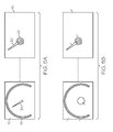
- FIG. 1 depicts a gauge according to this invention, including a flat panel display, a transparent panel, and a mechanical pointer including a hub affixed to an inboard face of the flat panel display or the transparent panel;
- FIG. 2 depicts an embodiment of the gauge of FIG. 1 in which a permanent magnet is integrated into the pointer, and a magnetic field generator is disposed behind the flat panel display;
- FIG. 3 depicts an embodiment of the gauge of FIG. 1 in which an electric motor is integrated into the pointer, and the motor is activated by transparent conductors formed on the flat panel display or the transparent panel;
- FIG. 4 depicts an embodiment of the gauge of FIG. 1 in which a LED is integrated into a hub of the pointer, and is activated by transparent conductors to illuminate a stem of the pointer;
- FIG. 5A depicts an embodiment of the gauge of FIG. 1 in which a stem of the pointer is illuminated by an image generated by flat panel display in visual alignment with the stem;
- FIG. 5B depicts an embodiment of the gauge of FIG. 1 in which a stem of the pointer is illuminated by light emitted from a region of the flat panel display in visual alignment with the pointer hub;
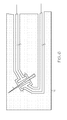
- FIG. 6 depicts an embodiment of the gauge of FIG. 1 in which a capacitive sensor defined by an array of transparent conductors formed on the flat panel display or the transparent panel senses a position of the pointer.
- the reference numeral 10 generally designates a configurable gauge according to this invention, including a flat panel display 12, a mechanical pointer 14, and a transparent panel 16.
- the flat panel display 12 is viewed through the transparent panel 16, and the pointer 14 is disposed between the flat panel display 12 and the transparent panel 16.
- the flat panel display 12 may be a color LCD for example, and is activated to portray traditional gauge face indicia and characters as shown, including arcuately arranged indicia 18 corresponding to a parameter of interest, along with various numeric and/or alphanumeric legends.
- the pointer 14 includes a stem or needle 20 and a hub 22 that rotatably supports the stem 20.
- the pointer hub 22 is affixed (with an adhesive material, for example) either to the inboard face 16a of transparent panel 16 as shown, or to the inboard face 12a of flat panel display 12.
- FIGS. 2-3 depict alternate ways of producing rotary motion of the stem 20 with respect to hub 22, and
- FIG. 2 depicts an embodiment in which rotation of the pointer stem 20 is controlled by magnetic effects.
- a permanent magnet 24 is integrated into stem 20 or the rotary portion of hub 22, and a magnetic field generator 26 is disposed behind the flat panel display 12 in substantial alignment with the permanent magnet 24.
- magnetic field generator 26 may comprise a set of mutually orthogonal coils or inductor components that are individually and variably excited to produce a magnetic field 28 that extends through the flat panel display 12 and interacts with the magnetic field of permanent magnet 24.
- the rotational orientation of the magnetic field 28 varies depending on how the magnetic field generator 26 is activated, and the permanent magnet 24 aligns with the magnetic field 28 to correspondingly position the pointer stem 20.
- magnetic field generator 26 may be mounted on a circuit board (not shown) or may be affixed directly to the outboard face 12b of flat panel display 12.
- FIG. 3 depicts an embodiment in which rotation of the pointer stem 20 is controlled with a micro-stepper motor 30 that is integrated into the pointer hub 22. That is, the stator of motor 30 is fixed to the stationary portion of hub 22, and the armature of motor 30 is fixed to the rotary portion of hub 22 (and hence, the stem 20).
- the windings of motor 30 are energized by a remotely disposed controller (not shown) to position the stem 20 via a set of transparent conductors 32 formed on the mounting surface of hub 22 (i.e., on the inboard face 16a of transparent panel 16 or the inboard face 12a of flat panel display 12).
- the transparent conductors 32 may be formed, for example, of Indium Tin Oxide (ITO).
- ITO Indium Tin Oxide
- FIG. 4 depicts an embodiment in which the stem 20 of pointer 14 is selectively illuminated by a LED 34 integrated into the pointer hub 22.
- Power is supplied to the LED 34 by a set of transparent conductors 36 formed on the mounting surface of hub 22 (i.e., on the inboard face 16a of transparent panel 16 or the inboard face 12a of flat panel display 12).
- the transparent conductors 36 may be formed, for example, of Indium Tin Oxide (ITO).
- ITO Indium Tin Oxide
- FIGS. 5A-5B depict various embodiments in which the stem 20 of pointer 14 is selectively illuminated by light emitted from the flat panel display 12. In each case, the assembly is depicted in partial exploded view to show the illumination pattern of the flat panel display 12.
- the flat panel display 12 is activated to produce an image 38 of pointer stem 20, and the image 38 rotates with pointer movement so that it is always in visual alignment with the stem 20.
- the stem 20 in this case may be an acrylic segment that contains fluorescent particles that fluoresce when excited by the light produced by the aligned image 38.
- a photo-sensor responsive to light of the fluorescing wavelengths may be installed at the edge of the display 12 to indicate the degree of coupling between image 38 and the stem 20 for purposes of maintaining proper alignment of the image 38 and stem 20.
- the stem 20 may contain a mixture of different fluorescent particles so that the perceived color of stem 20 is changed by changing the wavelength (i.e., color) of the image 38.
- the pointer stem 20 may be formed of a translucent frosted material so that the light produced by the aligned image 38 enters and diffuses through the stem 20. In that case, the pointer stem 20 simply takes on the color of the displayed image 38, and the pointer position must be accurately determined to ensure that the image 38 retains in visual alignment with the pointer stem 20.
- FIG. 6 illustrates one way to sense pointer position electrically, but in general, accurate knowledge of the pointer position may be sensed using various electrical, magnetic and mechanical sensing techniques.
- FIG. 5B differs from the embodiment of FIG. 5A in that the pointer illumination occurs due to light emitted by a circular region 40 of flat panel display 12 that is visually aligned with the pointer hub 22.
- the region 40 is the same for any pointer position.
- the hub 22 collects the emitted light and directs it down the pointer stem 20 similar to the embodiment of FIG. 4 where the LED 34 is integrated into the pointer hub 22.
- FIG. 6 illustrates a capacitive pointer position sensor defined by a pattern of transparent conductors 42, 44 formed on the inboard surface 12a of flat panel display 12 or the inboard surface 16a of transparent panel 16.
- the conductors 42 and 44 define first and second capacitive plates 46 and 48, respectively, and the position of the pointer stem 20 with respect to the plates 46 and 48 determines the capacitance between the conductors 42 and 44.
- more than one set of capacitive plates can be formed in this manner to provide redundancy and improved sensitivity.
- This type of sensing arrangement may be used to drive the pointer 14 to a specified position such a "zero" position, or to ensure that the pointer stem 20 (and the image 38, if applicable) are properly positioned by developing an error signal according to the deviation of the sensed position of stem 20 from the commanded position, and adjusting the pointer position to drive the error signal to zero.
- the gauge apparatus of the present invention provides an inexpensive and practical way of integrating a flat panel display with a mechanical pointer. While the present invention has been described with respect to the illustrated embodiments, it is recognized that numerous modifications and variations in addition to those mentioned herein will occur to those skilled in the art.
- the flat panel display 12 can be used to depict information in addition to the gauge face indicia 18, including other indicia, alphanumeric data, graphic images, and so forth. Accordingly, it is intended that the invention not be limited to the disclosed embodiment, but that it have the full scope permitted by the language of the following claims.
Landscapes
- Physics & Mathematics (AREA)
- General Physics & Mathematics (AREA)
- Engineering & Computer Science (AREA)
- Chemical & Material Sciences (AREA)
- Combustion & Propulsion (AREA)
- Transportation (AREA)
- Mechanical Engineering (AREA)
- Indicating Measured Values (AREA)
- Details Of Measuring Devices (AREA)
- Instrument Panels (AREA)
- Mechanical Control Devices (AREA)
Abstract
Description
- The present invention relates to instrumentation gauges in which a re-configurable flat panel display is used to display a user-defined gauge face representing a parameter of interest, and a rotary mechanical pointer disposed between the flat panel display and the user registers with indicia of the displayed gauge face to indicate a current value of the parameter.
- Reconfigurable flat panel displays have been used in automotive instrument clusters to electronically portray indicia, alphanumeric characters and legends customarily provided in printed or painted gauge faces. The advantages of the electronic approach include user-definability in terms of color and layout, and the ability to display different parameters or information in a single gauge-space. Although the current value of a parameter can be indicated in different ways, many people prefer displays that include a mechanical pointer or needle, even though the flat panel display can be used to electronically portray a pointer. However, providing a mechanical pointer in front of a flat panel display is non-trivial because it is impractical to drill a hole in the display to accommodate the pointer shaft.
- The present invention is directed to an improved gauge apparatus including a re-configurable flat panel display electrically activated to display a user-defined gauge face, including arcuately arranged indicia corresponding to a parameter of interest, a transparent panel spaced from the flat panel display through which the displayed gauge face is viewed, and a mechanical pointer disposed between the flat panel display and the transparent panel for indicating a current value of the parameter. The pointer includes a stem and a hub that rotatably supports the stem, and the hub is mounted on a surface of the flat panel display or a surface of the transparent panel. Rotation of the stem with respect to the hub is regulated either magnetically with a magnetic field generator disposed behind the flat panel display, or electrically with a motorized hub activated with transparent conductors formed on the flat panel display or transparent panel. The stem of the pointer is illuminated by either the flat panel display, or a hub-mounted LED activated with transparent conductors. Transparent conductors are also used to form a sensor array for detecting a position of the pointer and calibrating the gauge.
-
FIG. 1 depicts a gauge according to this invention, including a flat panel display, a transparent panel, and a mechanical pointer including a hub affixed to an inboard face of the flat panel display or the transparent panel; -
FIG. 2 depicts an embodiment of the gauge ofFIG. 1 in which a permanent magnet is integrated into the pointer, and a magnetic field generator is disposed behind the flat panel display; -
FIG. 3 depicts an embodiment of the gauge ofFIG. 1 in which an electric motor is integrated into the pointer, and the motor is activated by transparent conductors formed on the flat panel display or the transparent panel; -
FIG. 4 depicts an embodiment of the gauge ofFIG. 1 in which a LED is integrated into a hub of the pointer, and is activated by transparent conductors to illuminate a stem of the pointer; -
FIG. 5A depicts an embodiment of the gauge ofFIG. 1 in which a stem of the pointer is illuminated by an image generated by flat panel display in visual alignment with the stem; -
FIG. 5B depicts an embodiment of the gauge ofFIG. 1 in which a stem of the pointer is illuminated by light emitted from a region of the flat panel display in visual alignment with the pointer hub; and -
FIG. 6 depicts an embodiment of the gauge ofFIG. 1 in which a capacitive sensor defined by an array of transparent conductors formed on the flat panel display or the transparent panel senses a position of the pointer. - Referring to
FIG. 1 , thereference numeral 10 generally designates a configurable gauge according to this invention, including aflat panel display 12, amechanical pointer 14, and atransparent panel 16. Theflat panel display 12 is viewed through thetransparent panel 16, and thepointer 14 is disposed between theflat panel display 12 and thetransparent panel 16. Theflat panel display 12 may be a color LCD for example, and is activated to portray traditional gauge face indicia and characters as shown, including arcuately arrangedindicia 18 corresponding to a parameter of interest, along with various numeric and/or alphanumeric legends. Thepointer 14 includes a stem orneedle 20 and ahub 22 that rotatably supports thestem 20. Thepointer hub 22 is affixed (with an adhesive material, for example) either to theinboard face 16a oftransparent panel 16 as shown, or to theinboard face 12a offlat panel display 12.FIGS. 2-3 depict alternate ways of producing rotary motion of thestem 20 with respect tohub 22, andFIGS. 4 and5A-5B depict alternate ways of illuminating thestem 20. -
FIG. 2 depicts an embodiment in which rotation of thepointer stem 20 is controlled by magnetic effects. Apermanent magnet 24 is integrated intostem 20 or the rotary portion ofhub 22, and amagnetic field generator 26 is disposed behind theflat panel display 12 in substantial alignment with thepermanent magnet 24. Electrically,magnetic field generator 26 may comprise a set of mutually orthogonal coils or inductor components that are individually and variably excited to produce amagnetic field 28 that extends through theflat panel display 12 and interacts with the magnetic field ofpermanent magnet 24. The rotational orientation of themagnetic field 28 varies depending on how themagnetic field generator 26 is activated, and thepermanent magnet 24 aligns with themagnetic field 28 to correspondingly position thepointer stem 20. Mechanically,magnetic field generator 26 may be mounted on a circuit board (not shown) or may be affixed directly to theoutboard face 12b offlat panel display 12. -
FIG. 3 depicts an embodiment in which rotation of thepointer stem 20 is controlled with amicro-stepper motor 30 that is integrated into thepointer hub 22. That is, the stator ofmotor 30 is fixed to the stationary portion ofhub 22, and the armature ofmotor 30 is fixed to the rotary portion of hub 22 (and hence, the stem 20). The windings ofmotor 30 are energized by a remotely disposed controller (not shown) to position thestem 20 via a set oftransparent conductors 32 formed on the mounting surface of hub 22 (i.e., on theinboard face 16a oftransparent panel 16 or theinboard face 12a of flat panel display 12). Thetransparent conductors 32 may be formed, for example, of Indium Tin Oxide (ITO). -
FIG. 4 depicts an embodiment in which thestem 20 ofpointer 14 is selectively illuminated by aLED 34 integrated into thepointer hub 22. Power is supplied to theLED 34 by a set oftransparent conductors 36 formed on the mounting surface of hub 22 (i.e., on theinboard face 16a oftransparent panel 16 or theinboard face 12a of flat panel display 12). As with theconductors 32 ofFIG. 3 , thetransparent conductors 36 may be formed, for example, of Indium Tin Oxide (ITO). -
FIGS. 5A-5B depict various embodiments in which thestem 20 ofpointer 14 is selectively illuminated by light emitted from theflat panel display 12. In each case, the assembly is depicted in partial exploded view to show the illumination pattern of theflat panel display 12. - In the embodiment of
FIG. 5A , theflat panel display 12 is activated to produce animage 38 ofpointer stem 20, and theimage 38 rotates with pointer movement so that it is always in visual alignment with thestem 20. Thestem 20 in this case may be an acrylic segment that contains fluorescent particles that fluoresce when excited by the light produced by thealigned image 38. Advantageously, a photo-sensor responsive to light of the fluorescing wavelengths may be installed at the edge of thedisplay 12 to indicate the degree of coupling betweenimage 38 and thestem 20 for purposes of maintaining proper alignment of theimage 38 and stem 20. Also, thestem 20 may contain a mixture of different fluorescent particles so that the perceived color ofstem 20 is changed by changing the wavelength (i.e., color) of theimage 38. Alternately, thepointer stem 20 may be formed of a translucent frosted material so that the light produced by thealigned image 38 enters and diffuses through thestem 20. In that case, thepointer stem 20 simply takes on the color of the displayedimage 38, and the pointer position must be accurately determined to ensure that theimage 38 retains in visual alignment with thepointer stem 20.FIG. 6 illustrates one way to sense pointer position electrically, but in general, accurate knowledge of the pointer position may be sensed using various electrical, magnetic and mechanical sensing techniques. - The embodiment of
FIG. 5B differs from the embodiment ofFIG. 5A in that the pointer illumination occurs due to light emitted by acircular region 40 offlat panel display 12 that is visually aligned with thepointer hub 22. In this case, theregion 40 is the same for any pointer position. Thehub 22 collects the emitted light and directs it down thepointer stem 20 similar to the embodiment ofFIG. 4 where theLED 34 is integrated into thepointer hub 22. -
FIG. 6 illustrates a capacitive pointer position sensor defined by a pattern of transparent conductors 42, 44 formed on theinboard surface 12a offlat panel display 12 or theinboard surface 16a oftransparent panel 16. The conductors 42 and 44 define first and second capacitive plates 46 and 48, respectively, and the position of the pointer stem 20 with respect to the plates 46 and 48 determines the capacitance between the conductors 42 and 44. Of course, more than one set of capacitive plates can be formed in this manner to provide redundancy and improved sensitivity. This type of sensing arrangement may be used to drive thepointer 14 to a specified position such a "zero" position, or to ensure that the pointer stem 20 (and theimage 38, if applicable) are properly positioned by developing an error signal according to the deviation of the sensed position ofstem 20 from the commanded position, and adjusting the pointer position to drive the error signal to zero. - In summary, the gauge apparatus of the present invention provides an inexpensive and practical way of integrating a flat panel display with a mechanical pointer. While the present invention has been described with respect to the illustrated embodiments, it is recognized that numerous modifications and variations in addition to those mentioned herein will occur to those skilled in the art. For example, the
flat panel display 12 can be used to depict information in addition to thegauge face indicia 18, including other indicia, alphanumeric data, graphic images, and so forth. Accordingly, it is intended that the invention not be limited to the disclosed embodiment, but that it have the full scope permitted by the language of the following claims.
Claims (9)
- A configurable gauge (10) for indicating a current value of a parameter of interest, comprising:a re-configurable flat panel display (12) electrically activated to display a user-defined gauge face, including arcuately arranged indicia (18) corresponding to said parameter;a transparent panel (16) spaced from the flat panel display (12) through which the gauge face is viewed;a mechanical pointer (14) disposed between the flat panel display (12) and the transparent panel (16), including a stem (20) and a hub (22) that rotatably supports the stem (20), where the hub (22) is mounted on a surface (12a) of the flat panel display (12) or a surface (16a) of the transparent panel (16); andcontrol means for regulating a rotary position of the pointer stem (20) with respect to the arcuately arranged indicia (18) of the gauge face to indicate the current value of the parameter.
- The configurable gauge of claim 1, where said control means comprises:an electric motor (30) integrated into the hub (22) of the mechanical pointer (14), and effective when activated to rotate the stem (20) with respect to said hub (22);a motor controller for activating said electric motor (30) to regulate the rotary position of the pointer stem (20); andtransparent conductors (32) formed on a mounting surface of said hub (22) for electrically coupling said motor controller to said electric motor (30).
- The configurable gauge of claim 1, where said control means comprises:a permanent magnet (24) integrated into said mechanical pointer (14) and rotatable with said stem (20);a magnetic field generator (26) disposed behind the flat panel display (12) for generating a controllable magnetic field (28) that passes through the flat panel display (12) and interacts with a magnetic field of said permanent magnet (24) to affect the rotary position of the permanent magnet (24) and pointer stem (20); anda controller for controlling the magnetic field generator (26) so that the rotary position of the pointer stem (20) with respect to the arcuately arranged indicia (18) of the gauge face indicates the current value of the parameter.
- The configurable gauge of claim 1, further comprising:a LED (34) integrated into the hub (22) of said mechanical pointer (14) for illuminating the stem (20) of said pointer (14); andtransparent conductors (32) formed on a mounting surface of said hub (22) for electrically activating said LED (34) to illuminate said stem (20).
- The configurable gauge of claim 1, where:the stem (22) of said pointer (14) includes fluorescent particles that fluoresce when excited; andsaid control means activates a region (38, 40) of said flat panel display (12) that is in visual alignment with at least one of said stem (20) and said hub (22) to emit light that excites the fluorescent particles of said stem (20) and illuminate said stem (20).
- The configurable gauge of claim 5, where:the activated region (38) of said flat panel display (12) is in visual alignment with said stem (20);a photo-sensor is provided to sense fluorescence of said fluorescent particles; andsaid control means adjusts a position of said activated region (38) based on an output of said photo-sensor.
- The configurable gauge of claim 1, where:the stem (20) of said pointer (14) is formed of a translucent material; anda region (38, 40) of said flat panel display (12) that is in alignment with at least one of said stem (20) and said hub (22) is activated to emit light that passes through the translucent material of said stem (20).
- The configurable gauge of claim 7, where:said flat panel display (12) is activated to control a color of the emitted light that passes through the translucent material of said stem (20).
- The configurable gauge of claim 1, where:a capacitive sensor (46, 48) defined by a pattern of transparent conductors (42, 44) is formed the surface (12a) of the flat panel display (12) or the surface (16a) of the transparent panel (16) for detecting a position of said pointer stem (22); andsaid control means regulates the rotary position of the pointer stem (20) based on an output of the capacitive sensor (46, 48).
Applications Claiming Priority (1)
| Application Number | Priority Date | Filing Date | Title |
|---|---|---|---|
| US12/229,939 US7810444B2 (en) | 2008-08-28 | 2008-08-28 | Configurable gauge apparatus including a flat panel display and a mechanical pointer |
Publications (3)
| Publication Number | Publication Date |
|---|---|
| EP2159551A2 true EP2159551A2 (en) | 2010-03-03 |
| EP2159551A3 EP2159551A3 (en) | 2010-04-07 |
| EP2159551B1 EP2159551B1 (en) | 2018-04-18 |
Family
ID=41402101
Family Applications (1)
| Application Number | Title | Priority Date | Filing Date |
|---|---|---|---|
| EP09168215.3A Active EP2159551B1 (en) | 2008-08-28 | 2009-08-19 | Configurable gauge apparatus including a flat panel display and a mechanical pointer |
Country Status (2)
| Country | Link |
|---|---|
| US (1) | US7810444B2 (en) |
| EP (1) | EP2159551B1 (en) |
Cited By (4)
| Publication number | Priority date | Publication date | Assignee | Title |
|---|---|---|---|---|
| CN102331272A (en) * | 2010-07-10 | 2012-01-25 | 通用汽车环球科技运作有限责任公司 | The scale element that is used for indicating instrument, the vehicle of combination instrument and band scale element |
| DE102010032713A1 (en) * | 2010-07-29 | 2012-02-02 | Johnson Controls Automotive Electronics Gmbh | display device |
| DE102018220194A1 (en) | 2018-11-23 | 2020-05-28 | Volkswagen Aktiengesellschaft | Display device, display element, system and method for operating a display device |
| EP4043834A1 (en) * | 2021-02-11 | 2022-08-17 | Linde GmbH | Gauge apparatus including a flat panel display and a mechanical pointer |
Families Citing this family (12)
| Publication number | Priority date | Publication date | Assignee | Title |
|---|---|---|---|---|
| JP5099421B2 (en) * | 2007-03-21 | 2012-12-19 | 日本精機株式会社 | Indicator device |
| JP5007936B2 (en) * | 2007-04-11 | 2012-08-22 | 日本精機株式会社 | Indicator device |
| JP2009162713A (en) * | 2008-01-10 | 2009-07-23 | Nippon Seiki Co Ltd | Indicator device |
| US9808323B2 (en) * | 2009-06-04 | 2017-11-07 | Koninklijke Philips N.V. | Visualization apparatus |
| US8373331B2 (en) | 2010-09-15 | 2013-02-12 | Visteon Global Technologies, Inc. | Use of piezo motor to operate a ring pointer over display |
| US9096131B2 (en) * | 2012-01-06 | 2015-08-04 | Visteon Global Technologies, Inc. | Interactive display and gauge |
| US8757824B2 (en) | 2012-09-05 | 2014-06-24 | Visteon Global Technologies, Inc. | Pointer of an instrument driven with a shaftless stepper motor containing a lighting mechanism for lighting the pointer |
| US20140145839A1 (en) * | 2012-11-26 | 2014-05-29 | Delphi Technologies, Inc. | Reconfigurable instrument cluster assembly with a mechanical pointer overlying a mirror |
| US9605984B2 (en) | 2015-01-23 | 2017-03-28 | Visteon Global Technologies, Inc. | Electronic display assembly |
| EP3489001B1 (en) | 2017-11-22 | 2025-08-06 | Afros S.P.A. | Apparatus for fine and controlled adjustment of an injection molding process and related industrial process |
| US10787077B2 (en) * | 2018-11-20 | 2020-09-29 | Denso International America, Inc. | Floating ring pointer assembly |
| WO2023036423A1 (en) * | 2021-09-09 | 2023-03-16 | Siemens Aktiengesellschaft | Capacitive reading device for a pointer instrument |
Citations (1)
| Publication number | Priority date | Publication date | Assignee | Title |
|---|---|---|---|---|
| DE10046237A1 (en) | 2000-09-19 | 2002-04-04 | Bosch Gmbh Robert | Combination display for panels has face mounted motor allows easy assembly |
Family Cites Families (15)
| Publication number | Priority date | Publication date | Assignee | Title |
|---|---|---|---|---|
| US3992655A (en) * | 1974-09-16 | 1976-11-16 | Dieterich Standard Corporation | Electronic meter signalling device |
| JPS54148158U (en) * | 1978-04-05 | 1979-10-15 | ||
| FR2627864A1 (en) * | 1988-02-29 | 1989-09-01 | Asulab Sa | DISPLAY DEVICE FOR MEASURING INSTRUMENT |
| FR2729345B1 (en) | 1995-01-18 | 1997-04-18 | Magneti Marelli France | IMPROVED DASHBOARD FOR MOTOR VEHICLE |
| JPH08327410A (en) | 1995-05-31 | 1996-12-13 | Nippon Seiki Co Ltd | Pointer type instrument |
| DE19537666C2 (en) | 1995-10-10 | 2002-05-29 | Optrex Europ Gmbh | pointer instrument |
| DE19615499A1 (en) * | 1996-04-19 | 1997-10-23 | Vdo Schindling | Pointer instrument |
| JPH11118537A (en) | 1997-10-20 | 1999-04-30 | Kansei Corp | Meter display device |
| FR2770643B1 (en) | 1997-11-06 | 2000-02-04 | Magneti Marelli France | NEEDLE INDICATOR FOR MOTOR VEHICLE DASHBOARD |
| DE10153102B4 (en) * | 2001-10-30 | 2008-10-16 | Continental Automotive Gmbh | pointer instrument |
| JP2003161650A (en) * | 2001-11-28 | 2003-06-06 | Nippon Seiki Co Ltd | Indicating instrument device |
| US6827034B1 (en) * | 2002-09-25 | 2004-12-07 | Yazaki North America, Inc. | Illuminated dial and pointer display |
| US7159534B2 (en) * | 2003-11-25 | 2007-01-09 | Yazaki Corporation | Display unit having a center display |
| US7731374B2 (en) * | 2005-10-24 | 2010-06-08 | Continental Automotive Systems Us, Inc. | Reconfigurable instrument cluster |
| DE102006047896A1 (en) | 2006-10-10 | 2008-04-17 | Volkswagen Ag | Displaying device for instrument cluster of motor vehicle, has magnetofluid arranged between indicator device and stationary part of displaying device, where magnetic field holds magnetofluid that dampens oscillations of displaying device |
-
2008
- 2008-08-28 US US12/229,939 patent/US7810444B2/en active Active
-
2009
- 2009-08-19 EP EP09168215.3A patent/EP2159551B1/en active Active
Patent Citations (1)
| Publication number | Priority date | Publication date | Assignee | Title |
|---|---|---|---|---|
| DE10046237A1 (en) | 2000-09-19 | 2002-04-04 | Bosch Gmbh Robert | Combination display for panels has face mounted motor allows easy assembly |
Cited By (6)
| Publication number | Priority date | Publication date | Assignee | Title |
|---|---|---|---|---|
| CN102331272A (en) * | 2010-07-10 | 2012-01-25 | 通用汽车环球科技运作有限责任公司 | The scale element that is used for indicating instrument, the vehicle of combination instrument and band scale element |
| CN102331272B (en) * | 2010-07-10 | 2015-12-02 | 通用汽车环球科技运作有限责任公司 | Be used to indicate the scale element of instrument, the vehicle of combination instrument and element with a scale |
| DE102010032713A1 (en) * | 2010-07-29 | 2012-02-02 | Johnson Controls Automotive Electronics Gmbh | display device |
| WO2012013257A3 (en) * | 2010-07-29 | 2012-04-26 | Johnson Controls Automotive Electronics Gmbh | Indicating device |
| DE102018220194A1 (en) | 2018-11-23 | 2020-05-28 | Volkswagen Aktiengesellschaft | Display device, display element, system and method for operating a display device |
| EP4043834A1 (en) * | 2021-02-11 | 2022-08-17 | Linde GmbH | Gauge apparatus including a flat panel display and a mechanical pointer |
Also Published As
| Publication number | Publication date |
|---|---|
| EP2159551A3 (en) | 2010-04-07 |
| US7810444B2 (en) | 2010-10-12 |
| US20100050927A1 (en) | 2010-03-04 |
| EP2159551B1 (en) | 2018-04-18 |
Similar Documents
| Publication | Publication Date | Title |
|---|---|---|
| US7810444B2 (en) | Configurable gauge apparatus including a flat panel display and a mechanical pointer | |
| US7629874B2 (en) | Needle meter and method for manufacturing the same | |
| CN110073581A (en) | Stepper motor and vehicle pointer meters | |
| CN102334014A (en) | pointer measuring instrument | |
| JP2009183492A (en) | Display device | |
| CN100578158C (en) | indicating measuring instrument | |
| EP2679965A2 (en) | Needle indicator oriented by periphery electromagnets | |
| US20080100841A1 (en) | Pointer instrument for automotive meter | |
| KR101784732B1 (en) | Thin gauge with self-emitting display for hidden pointer | |
| JP2003315106A (en) | Lighting system | |
| JP2003254794A (en) | Lighting apparatus | |
| JP2002126231A (en) | Symbol display device and gaming machine | |
| JPH07113663A (en) | Instrumentation | |
| JP2004361182A (en) | Pointer instrument for vehicles | |
| CN206297415U (en) | Metering device and vehicular meter system | |
| JPH11170890A (en) | Display device for vehicles | |
| JP2765430B2 (en) | Instrument equipment | |
| JPH0511461Y2 (en) | ||
| JP2001241968A (en) | Measuring-instrument | |
| JP4147908B2 (en) | Game machine | |
| JP2005049239A (en) | Lighting device for vehicle instrument | |
| JP7623740B2 (en) | Three-dimensional screen device having pixel-by-pixel appearance structure and control method thereof | |
| JP5477623B2 (en) | Pointer-type instrument | |
| JP2010243415A (en) | Display device | |
| JP2008295577A (en) | Game machine |
Legal Events
| Date | Code | Title | Description |
|---|---|---|---|
| PUAI | Public reference made under article 153(3) epc to a published international application that has entered the european phase |
Free format text: ORIGINAL CODE: 0009012 |
|
| AK | Designated contracting states |
Kind code of ref document: A2 Designated state(s): AT BE BG CH CY CZ DE DK EE ES FI FR GB GR HR HU IE IS IT LI LT LU LV MC MK MT NL NO PL PT RO SE SI SK SM TR |
|
| AX | Request for extension of the european patent |
Extension state: AL BA RS |
|
| PUAL | Search report despatched |
Free format text: ORIGINAL CODE: 0009013 |
|
| AK | Designated contracting states |
Kind code of ref document: A3 Designated state(s): AT BE BG CH CY CZ DE DK EE ES FI FR GB GR HR HU IE IS IT LI LT LU LV MC MK MT NL NO PL PT RO SE SI SK SM TR |
|
| AX | Request for extension of the european patent |
Extension state: AL BA RS |
|
| 17P | Request for examination filed |
Effective date: 20101007 |
|
| 17Q | First examination report despatched |
Effective date: 20170602 |
|
| GRAP | Despatch of communication of intention to grant a patent |
Free format text: ORIGINAL CODE: EPIDOSNIGR1 |
|
| RIC1 | Information provided on ipc code assigned before grant |
Ipc: G01D 13/04 20060101ALI20171002BHEP Ipc: G01D 11/28 20060101AFI20171002BHEP Ipc: B60K 37/02 20060101ALI20171002BHEP |
|
| INTG | Intention to grant announced |
Effective date: 20171108 |
|
| GRAS | Grant fee paid |
Free format text: ORIGINAL CODE: EPIDOSNIGR3 |
|
| GRAA | (expected) grant |
Free format text: ORIGINAL CODE: 0009210 |
|
| AK | Designated contracting states |
Kind code of ref document: B1 Designated state(s): AT BE BG CH CY CZ DE DK EE ES FI FR GB GR HR HU IE IS IT LI LT LU LV MC MK MT NL NO PL PT RO SE SI SK SM TR |
|
| REG | Reference to a national code |
Ref country code: GB Ref legal event code: FG4D |
|
| REG | Reference to a national code |
Ref country code: CH Ref legal event code: EP |
|
| REG | Reference to a national code |
Ref country code: AT Ref legal event code: REF Ref document number: 990984 Country of ref document: AT Kind code of ref document: T Effective date: 20180515 |
|
| REG | Reference to a national code |
Ref country code: IE Ref legal event code: FG4D |
|
| REG | Reference to a national code |
Ref country code: DE Ref legal event code: R096 Ref document number: 602009051820 Country of ref document: DE |
|
| REG | Reference to a national code |
Ref country code: NL Ref legal event code: MP Effective date: 20180418 |
|
| REG | Reference to a national code |
Ref country code: FR Ref legal event code: PLFP Year of fee payment: 10 |
|
| REG | Reference to a national code |
Ref country code: LT Ref legal event code: MG4D |
|
| PG25 | Lapsed in a contracting state [announced via postgrant information from national office to epo] |
Ref country code: NL Free format text: LAPSE BECAUSE OF FAILURE TO SUBMIT A TRANSLATION OF THE DESCRIPTION OR TO PAY THE FEE WITHIN THE PRESCRIBED TIME-LIMIT Effective date: 20180418 |
|
| PG25 | Lapsed in a contracting state [announced via postgrant information from national office to epo] |
Ref country code: LT Free format text: LAPSE BECAUSE OF FAILURE TO SUBMIT A TRANSLATION OF THE DESCRIPTION OR TO PAY THE FEE WITHIN THE PRESCRIBED TIME-LIMIT Effective date: 20180418 Ref country code: BG Free format text: LAPSE BECAUSE OF FAILURE TO SUBMIT A TRANSLATION OF THE DESCRIPTION OR TO PAY THE FEE WITHIN THE PRESCRIBED TIME-LIMIT Effective date: 20180718 Ref country code: PL Free format text: LAPSE BECAUSE OF FAILURE TO SUBMIT A TRANSLATION OF THE DESCRIPTION OR TO PAY THE FEE WITHIN THE PRESCRIBED TIME-LIMIT Effective date: 20180418 Ref country code: ES Free format text: LAPSE BECAUSE OF FAILURE TO SUBMIT A TRANSLATION OF THE DESCRIPTION OR TO PAY THE FEE WITHIN THE PRESCRIBED TIME-LIMIT Effective date: 20180418 Ref country code: FI Free format text: LAPSE BECAUSE OF FAILURE TO SUBMIT A TRANSLATION OF THE DESCRIPTION OR TO PAY THE FEE WITHIN THE PRESCRIBED TIME-LIMIT Effective date: 20180418 Ref country code: NO Free format text: LAPSE BECAUSE OF FAILURE TO SUBMIT A TRANSLATION OF THE DESCRIPTION OR TO PAY THE FEE WITHIN THE PRESCRIBED TIME-LIMIT Effective date: 20180718 Ref country code: SE Free format text: LAPSE BECAUSE OF FAILURE TO SUBMIT A TRANSLATION OF THE DESCRIPTION OR TO PAY THE FEE WITHIN THE PRESCRIBED TIME-LIMIT Effective date: 20180418 |
|
| PG25 | Lapsed in a contracting state [announced via postgrant information from national office to epo] |
Ref country code: LV Free format text: LAPSE BECAUSE OF FAILURE TO SUBMIT A TRANSLATION OF THE DESCRIPTION OR TO PAY THE FEE WITHIN THE PRESCRIBED TIME-LIMIT Effective date: 20180418 Ref country code: GR Free format text: LAPSE BECAUSE OF FAILURE TO SUBMIT A TRANSLATION OF THE DESCRIPTION OR TO PAY THE FEE WITHIN THE PRESCRIBED TIME-LIMIT Effective date: 20180719 Ref country code: HR Free format text: LAPSE BECAUSE OF FAILURE TO SUBMIT A TRANSLATION OF THE DESCRIPTION OR TO PAY THE FEE WITHIN THE PRESCRIBED TIME-LIMIT Effective date: 20180418 |
|
| REG | Reference to a national code |
Ref country code: DE Ref legal event code: R081 Ref document number: 602009051820 Country of ref document: DE Owner name: APTIV TECHNOLOGIES LIMITED, BB Free format text: FORMER OWNER: DELPHI TECHNOLOGIES, INC., TROY, MICH., US |
|
| REG | Reference to a national code |
Ref country code: AT Ref legal event code: MK05 Ref document number: 990984 Country of ref document: AT Kind code of ref document: T Effective date: 20180418 |
|
| PG25 | Lapsed in a contracting state [announced via postgrant information from national office to epo] |
Ref country code: PT Free format text: LAPSE BECAUSE OF FAILURE TO SUBMIT A TRANSLATION OF THE DESCRIPTION OR TO PAY THE FEE WITHIN THE PRESCRIBED TIME-LIMIT Effective date: 20180820 |
|
| REG | Reference to a national code |
Ref country code: DE Ref legal event code: R097 Ref document number: 602009051820 Country of ref document: DE |
|
| PG25 | Lapsed in a contracting state [announced via postgrant information from national office to epo] |
Ref country code: DK Free format text: LAPSE BECAUSE OF FAILURE TO SUBMIT A TRANSLATION OF THE DESCRIPTION OR TO PAY THE FEE WITHIN THE PRESCRIBED TIME-LIMIT Effective date: 20180418 Ref country code: RO Free format text: LAPSE BECAUSE OF FAILURE TO SUBMIT A TRANSLATION OF THE DESCRIPTION OR TO PAY THE FEE WITHIN THE PRESCRIBED TIME-LIMIT Effective date: 20180418 Ref country code: SK Free format text: LAPSE BECAUSE OF FAILURE TO SUBMIT A TRANSLATION OF THE DESCRIPTION OR TO PAY THE FEE WITHIN THE PRESCRIBED TIME-LIMIT Effective date: 20180418 Ref country code: CZ Free format text: LAPSE BECAUSE OF FAILURE TO SUBMIT A TRANSLATION OF THE DESCRIPTION OR TO PAY THE FEE WITHIN THE PRESCRIBED TIME-LIMIT Effective date: 20180418 Ref country code: AT Free format text: LAPSE BECAUSE OF FAILURE TO SUBMIT A TRANSLATION OF THE DESCRIPTION OR TO PAY THE FEE WITHIN THE PRESCRIBED TIME-LIMIT Effective date: 20180418 Ref country code: EE Free format text: LAPSE BECAUSE OF FAILURE TO SUBMIT A TRANSLATION OF THE DESCRIPTION OR TO PAY THE FEE WITHIN THE PRESCRIBED TIME-LIMIT Effective date: 20180418 |
|
| REG | Reference to a national code |
Ref country code: GB Ref legal event code: 732E Free format text: REGISTERED BETWEEN 20190117 AND 20190123 |
|
| REG | Reference to a national code |
Ref country code: GB Ref legal event code: 732E Free format text: REGISTERED BETWEEN 20190124 AND 20190130 |
|
| PLBE | No opposition filed within time limit |
Free format text: ORIGINAL CODE: 0009261 |
|
| STAA | Information on the status of an ep patent application or granted ep patent |
Free format text: STATUS: NO OPPOSITION FILED WITHIN TIME LIMIT |
|
| PG25 | Lapsed in a contracting state [announced via postgrant information from national office to epo] |
Ref country code: IT Free format text: LAPSE BECAUSE OF FAILURE TO SUBMIT A TRANSLATION OF THE DESCRIPTION OR TO PAY THE FEE WITHIN THE PRESCRIBED TIME-LIMIT Effective date: 20180418 Ref country code: SM Free format text: LAPSE BECAUSE OF FAILURE TO SUBMIT A TRANSLATION OF THE DESCRIPTION OR TO PAY THE FEE WITHIN THE PRESCRIBED TIME-LIMIT Effective date: 20180418 |
|
| 26N | No opposition filed |
Effective date: 20190121 |
|
| PG25 | Lapsed in a contracting state [announced via postgrant information from national office to epo] |
Ref country code: MC Free format text: LAPSE BECAUSE OF FAILURE TO SUBMIT A TRANSLATION OF THE DESCRIPTION OR TO PAY THE FEE WITHIN THE PRESCRIBED TIME-LIMIT Effective date: 20180418 |
|
| REG | Reference to a national code |
Ref country code: CH Ref legal event code: PL |
|
| PG25 | Lapsed in a contracting state [announced via postgrant information from national office to epo] |
Ref country code: LI Free format text: LAPSE BECAUSE OF NON-PAYMENT OF DUE FEES Effective date: 20180831 Ref country code: CH Free format text: LAPSE BECAUSE OF NON-PAYMENT OF DUE FEES Effective date: 20180831 Ref country code: LU Free format text: LAPSE BECAUSE OF NON-PAYMENT OF DUE FEES Effective date: 20180819 |
|
| REG | Reference to a national code |
Ref country code: BE Ref legal event code: MM Effective date: 20180831 |
|
| REG | Reference to a national code |
Ref country code: IE Ref legal event code: MM4A |
|
| PG25 | Lapsed in a contracting state [announced via postgrant information from national office to epo] |
Ref country code: SI Free format text: LAPSE BECAUSE OF FAILURE TO SUBMIT A TRANSLATION OF THE DESCRIPTION OR TO PAY THE FEE WITHIN THE PRESCRIBED TIME-LIMIT Effective date: 20180418 |
|
| PG25 | Lapsed in a contracting state [announced via postgrant information from national office to epo] |
Ref country code: IE Free format text: LAPSE BECAUSE OF NON-PAYMENT OF DUE FEES Effective date: 20180819 |
|
| PG25 | Lapsed in a contracting state [announced via postgrant information from national office to epo] |
Ref country code: BE Free format text: LAPSE BECAUSE OF NON-PAYMENT OF DUE FEES Effective date: 20180831 |
|
| PG25 | Lapsed in a contracting state [announced via postgrant information from national office to epo] |
Ref country code: MT Free format text: LAPSE BECAUSE OF NON-PAYMENT OF DUE FEES Effective date: 20180819 |
|
| PG25 | Lapsed in a contracting state [announced via postgrant information from national office to epo] |
Ref country code: TR Free format text: LAPSE BECAUSE OF FAILURE TO SUBMIT A TRANSLATION OF THE DESCRIPTION OR TO PAY THE FEE WITHIN THE PRESCRIBED TIME-LIMIT Effective date: 20180418 |
|
| PG25 | Lapsed in a contracting state [announced via postgrant information from national office to epo] |
Ref country code: HU Free format text: LAPSE BECAUSE OF FAILURE TO SUBMIT A TRANSLATION OF THE DESCRIPTION OR TO PAY THE FEE WITHIN THE PRESCRIBED TIME-LIMIT; INVALID AB INITIO Effective date: 20090819 |
|
| PG25 | Lapsed in a contracting state [announced via postgrant information from national office to epo] |
Ref country code: MK Free format text: LAPSE BECAUSE OF NON-PAYMENT OF DUE FEES Effective date: 20180418 Ref country code: CY Free format text: LAPSE BECAUSE OF FAILURE TO SUBMIT A TRANSLATION OF THE DESCRIPTION OR TO PAY THE FEE WITHIN THE PRESCRIBED TIME-LIMIT Effective date: 20180418 |
|
| PG25 | Lapsed in a contracting state [announced via postgrant information from national office to epo] |
Ref country code: IS Free format text: LAPSE BECAUSE OF FAILURE TO SUBMIT A TRANSLATION OF THE DESCRIPTION OR TO PAY THE FEE WITHIN THE PRESCRIBED TIME-LIMIT Effective date: 20180818 |
|
| P01 | Opt-out of the competence of the unified patent court (upc) registered |
Effective date: 20230425 |
|
| REG | Reference to a national code |
Ref country code: DE Ref legal event code: R081 Ref document number: 602009051820 Country of ref document: DE Owner name: APTIV TECHNOLOGIES AG, CH Free format text: FORMER OWNER: APTIV TECHNOLOGIES LIMITED, ST. MICHAEL, BB |
|
| PGFP | Annual fee paid to national office [announced via postgrant information from national office to epo] |
Ref country code: DE Payment date: 20250722 Year of fee payment: 17 |
|
| PGFP | Annual fee paid to national office [announced via postgrant information from national office to epo] |
Ref country code: GB Payment date: 20250818 Year of fee payment: 17 |
|
| PGFP | Annual fee paid to national office [announced via postgrant information from national office to epo] |
Ref country code: FR Payment date: 20250812 Year of fee payment: 17 |