EP2159123A1 - Mechanical installation for transporting a person on a bicycle or similar - Google Patents
Mechanical installation for transporting a person on a bicycle or similar Download PDFInfo
- Publication number
- EP2159123A1 EP2159123A1 EP09354034A EP09354034A EP2159123A1 EP 2159123 A1 EP2159123 A1 EP 2159123A1 EP 09354034 A EP09354034 A EP 09354034A EP 09354034 A EP09354034 A EP 09354034A EP 2159123 A1 EP2159123 A1 EP 2159123A1
- Authority
- EP
- European Patent Office
- Prior art keywords
- pedal
- zone
- carriage
- pusher device
- movement
- Prior art date
- Legal status (The legal status is an assumption and is not a legal conclusion. Google has not performed a legal analysis and makes no representation as to the accuracy of the status listed.)
- Granted
Links
Images


Classifications
-
- B—PERFORMING OPERATIONS; TRANSPORTING
- B61—RAILWAYS
- B61B—RAILWAY SYSTEMS; EQUIPMENT THEREFOR NOT OTHERWISE PROVIDED FOR
- B61B11/00—Ski lift, sleigh lift or like trackless systems with guided towing cables only
- B61B11/004—Means connecting load and cable
- B61B11/006—Means connecting load and cable the load being a cycle
Definitions
- the invention relates to a mechanical installation for transporting a person on a bicycle or the like, comprising a wire drive means arranged in a closed loop housed in the ground and driven in a scrolling movement between two zones respectively of departure and arrival, at least one pusher device being coupled to it to propel a foot of the person during the movement of the pusher device from the starting area to the arrival area.
- Each pushing device of an installation of this kind is intended to ensure the movement of a person in a light and individual transport vehicle such as a bicycle or the like, such as a scooter.
- the object of the invention is to provide an installation of the type mentioned above, which has improved security.
- An installation according to the invention makes it possible to guarantee that, in the event of loss of the position of equilibrium by the pushed person, the entire pusher device comes to disappear immediately and automatically under the ground thanks to the passage of the pedal towards its retracted position.
- the means allowing the locking mechanism to automatically occupy its inactive state in the absence of pressure force applied to the pedal during the movement of the carriage of the departure zone to the arrival zone are constituted by elastic return means able to move the locking element relative to the retaining element, which may occupy either a natural configuration in which the elements are not in position. contact, an elastically deformed configuration with respect to its natural configuration and in which the elements are in contact.
- the invention relates to a mechanical installation for transporting a person placed on a light and individual transport vehicle such as a bicycle or the like, such as a scooter.
- the installation comprises a wire drive means 10, for example a cable or a chain, arranged in a closed loop housed in a gap 11 arranged in the ground 12.
- the gap 11 connects a departure zone and an arrival zone between which the installation carries out the transport of the persons.
- the wired drive means 10 is driven in a scrolling movement between the two zones, so that one of its strands goes from the departure zone to the arrival zone (see arrow 13).
- a motorization mechanism in the arrival zone and a tensioning mechanism in the starting zone or conversely a motorization mechanism in the starting zone and a tensioning mechanism in the starting zone. the arrival area. It is also conceivable to develop in the arrival zone a mechanism dedicated to both the motorization and the tensioning, the starting zone then being equipped with a fixed return mechanism.
- At least one pusher device is coupled to the wire drive 10 for propelling a foot 14 of the person during movement of the pusher device from the starting area to the area of arrival according to the arrow 13.
- each pusher device comprises a carriage 15, a thrust pedal 16, and a locking mechanism described below.
- the carriage 15 is equipped with a latching lug 17 to the wired drive means 10 and rolling means associated with guide means arranged in the ground 12 between the departure zone and the arrival zone.
- the trench-shaped gap 11 formed in the ground between the departure and arrival zones has forms adapted to receive the carriage 15.
- the rolling means comprise a pair of horizontal rollers 18, 19 arranged at the ends of the carriage in its displacement direction, and two pairs of vertical rollers 20 to 23.
- the pair of vertical rollers 20, 21 is positioned near the horizontal roller 18 towards the front of the carriage 15, while a pair of vertical rollers 22, 23 is positioned at the horizontal roller 19 towards the rear of the carriage 15.
- the horizontal rollers 18, 19 and vertical 20 to 23 roll in two lateral rails 24, 25 bordering the gap 11.
- Each lateral rail 24, 25 has a U-shaped section. open towards the side rail 24, 25 opposite. Potentially, the rails 24, 25 may have a curvature allowing the pusher device to move in a path having curves symbolized by the mark R on the figure 3 .
- the thrust pedal 16 has an active face 26 on which the foot 14 comes to bear during the propulsion operation starting simultaneously with the moving operation of the pusher device from the starting zone to the arrival zone.
- the thrust pedal 16 has a triangular shape in a vertical longitudinal plane and the active face 26 is constituted by the upper edge of this triangle.
- the foot 14 exerts a pressing force F ( figure 4 ) during the propulsion of the foot 14.
- the thrust pedal 16 is pivotally mounted on the carriage 15 to selectively occupy, during the movement of the carriage 15 from the starting zone to the arrival zone, a position protruding from the ground ( figure 1 and 4 ), a retracted position in the ground 12 inside the gap 11 ( figure 6 ).
- a light 27 is arranged through the carriage 15.
- the thrust pedal 16 In the protruding position of the ground, the thrust pedal 16 is positioned on one side of the light 27, generally on above the carriage 15. In the retracted position, the thrust pedal 16 is positioned on the other side of the light 27, generally below the carriage 15.
- the pivotal mounting of the thrust pedal 16 on the carriage 15 is realized using a hinge 28 provided in the front part of the thrust pedal 16, adapted to pivot the pedal 16 in a vertical longitudinal plane centered laterally on the carriage 15.
- a pawl 29 is pivotally mounted on the thrust pedal 16 according to a hinge 30 located in the upper part of the pedal, that is to say behind and above the hinge 28.
- the ratchet 29 is placed in a central housing of the pedal 16 defined by two lateral flanks of the pedal 16.
- the pawl has substantially a circular arc shape and the hinge 30 is arranged substantially in the middle of the arc. It has a convex upper edge facing upwards and a concave lower edge turned towards the bottom of the gap 11 through the light 27.
- a locking element 31 At the rear end of the pawl 29 is provided a locking element 31 arranged projecting longitudinally relative to the arched body of the pawl 29.
- the convex upper edge particularly in the portion of the pawl 29 in front of the hinge 30, has the possibility of projecting towards the top of the active face 26 of the pedal 13, by pivoting about the hinge 30, through a slot 32 arranged in the active face 26 and opening on the central housing of the pedal 16.
- a straight stroke return spring 33 is attached at one end to the pedal 16 at a point of attachment slightly rearward of the hinge 28, and at its opposite end to the pawl portion 29 located behind the hinge 30. .
- the length of the return spring 33 is chosen so that in its natural configuration, it keeps the pawl 29 in an angular position relative to the thrust pedal 16, such that the front portion of the convex upper edge of the pawl 29 is protruding from the active face 26 of the pedal 16.
- a pressing force F is applied to the active face 26, this force F has the effect of eliminating this projecting position relative to the active face 26, causing the pivoting of the pawl 29 relative to the pedal 16 around the hinge 30 and the passage of the return spring 33 to a deformed configuration (in this case by elongation) elastically with respect to its natural configuration.
- the return spring 33 constitutes means allowing the locking mechanism to automatically assume its inactive state in the absence of pressure force applied to the pedal 16 during the movement of the trolley from the departure area to the arrival area.
- the design of the pusher device could be modified within the scope of the invention, providing in particular that the pawl is articulated on the carriage and that the retaining element is integral with the thrust pedal.
- the return spring would be fixed at one end to the carriage and at its opposite end to the pawl.
- the mechanical transport installation comprises means for automatically placing the thrust pedal 16 in the protruding position of the ground when the pusher device passes to a first predetermined location situated in the starting zone or directly upstream thereof. the direction of movement of the pusher device.
- Such means are for example constituted by a ramp secured to the pedal 16 and intended to cooperate automatically with a fixed lift ramp arranged at said first location in the gap 11 at the time of passage of the pusher device at said first location.
- Such lifting means ensure that the thrust pedal 16 is already in position protruding from the ground when the pressing force F is likely to be applied in the starting area, then passing the locking mechanism to its active state.
- Such lifting means can indifferently be globally integrated on board the pusher device, for example by means of a motor controlling the pivoting of the pedal and controlled according to the position of the pusher device along the installation.
- a motor controlling the pivoting of the pedal and controlled according to the position of the pusher device along the installation.
- the passage of the thrust pedal 16 to the projecting position of the ground is controlled by the application of the pressing force F itself.
- the particularity of the pawl 29 to project from the active face 26 in the natural configuration of the return spring 33 constitutes means for putting the locking mechanism in its active state in the starting zone.
- these means being actuated by the application of a pressing force F on the pedal 16 to the passage of the pusher device in the starting zone.
- the application of a pressing force F controls the transition to the active state of the locking mechanism. It is clear that it may however be envisaged to provide means for putting the locking mechanism in its active state directly upstream of the departure zone in the direction of movement of the pusher device.
- the means for putting the locking mechanism in its active state would be automatically actuated by the passage of the pusher device to a second predetermined location located in the starting zone or upstream thereof in the direction of movement of the pusher device said second location being disposed downstream of the first location.
- the transition to the active state of the locking mechanism would be automatically performed before any subsequent application of a pressing force F in the starting area.
- the figure 5 illustrates that when the pressing force F ceases, the return spring 33 returns to its natural configuration, controlling the pivoting of the pawl 29 and the displacement of the movable blocking element 31 to a location where the movable blocking element 31 is no longer able to come into mechanical contact with the retaining element 34 when the pedal 16 tends to return to the retracted position, which is the case under the effect of gravity.
- the return spring 33 ensures the passage of the locking mechanism to its inactive state, eliminating any possibility of mechanical contact between the elements 31 and 34, and allowing the pedal to come to occupy its retracted position by pivoting under the effect of its proper weight ( figure 6 ).
- the return spring 33 thus constitutes elastic return means able to move the locking element 31 relative to the retaining element 34, and likely to occupy either a natural configuration in which the elements 31, 34 are not in contact, that is to say an elastically deformed configuration with respect to its natural configuration and in which the elements are in contact.
- Other modes of elastic deformation could be envisaged, such as torsion or compression.
- the transition from the natural configuration to the deformed configuration of the return spring 33 is controlled by the means for putting the locking mechanism in its active state, ie the application of a pressing force F, while the passage of the Deformed configuration with the natural configuration results, in the event of absence of pressure force F on the pedal, of the elasticity of the return spring 33.
- shutters 35, 36 can be arranged in the upper part of the gap 11 at the surface of the ground 12, with the aid of a mechanism for moving them laterally relative to the other, between a remote position providing access to the interior of the gap 11, and a close position in which their distal edges are placed at a spacing just enough to allow the longitudinal displacement of the thrust pedal 16.
- the mechanism may include means for returning the shutters 35, 36 to the close position, interposed either between the two shutters, or between each of the shutters and a vertical lateral flank dug in the ground.
- the pawl 29 is removed, but the fixed retention element 34 is always present at the rear of the pusher pedal 16.
- This is mounted on the carriage 15 in a connection mechanical providing, independently of one another, a free pivoting of horizontal lateral axis and a free translation of substantially longitudinal direction, of the pedal 16 relative to the carriage 15.
- the pedal can incorporate a oblong opening 37 inside which an axis 38 integral with the carriage 15 is mounted. The oblong opening 37 is arranged at the location of the articulation 28 of the first mode of production.
- the rectilinear return spring 33 is fixed at one end to a point of the pedal 16 in front of the oblong opening 37, and at its end opposite a point of the carriage 15 situated in front of the thrust pedal 16.
- the locking element 39 considered to be an integral part of the locking mechanism according to the invention, is for its part constituted by the lower rear end of the thrust pedal.
- the locking element belonging to the locking mechanism according to the invention can therefore be integral with a pawl independent of the pedal 16 or the carriage 15 as was the case in the first embodiment, but can also be integral with the pedal 16 itself, which is the case for this second embodiment.
- the locking mechanism it could be envisaged to make the locking element integral with the carriage 15. In this case, care should be taken to provide the retaining element integral with the thrust pedal 16.
- the length of the return spring 33 is chosen so that in its natural configuration, it keeps the pedal 16 in a longitudinal position with respect to the carriage 15 such that the locking element 39 and the retaining element 34 can not not come into mechanical contact with each other regardless of the angular position of the thrust pedal 16 relative to the carriage 15 about the axis 38.
- a pressing force F is applied to the active face 26, this effort F has the effect of causing a longitudinal recoil of the pedal 16, rearwardly, by sliding of the axis 38 in the oblong opening.
- This recoil of the pedal 16 involves the passage of the return spring 33 to a deformed configuration (in this case by elongation) elastically with respect to its natural configuration and the locking element 39 undergoes a displacement such that the elements 39 and 34 automatically come into contact with each other when the pedal 16 tends to move towards the retracted position, forcing it to stay in position protruding from the ground.
- the natural return of the return spring 33 to its natural configuration when the pressing force F stops causes the reverse movement of the pedal 16, releasing the locking element 39 relative to the retaining element 34 by eliminating any possibility of contact between the elements 34, 39 regardless of the angular position of the pedal 16 with respect to the carriage 15.
- the figure 8 illustrates that when the presser force F ceases, the return spring 33 returns to its natural configuration, controlling the longitudinal return of the pedal 16 forwards and the displacement of the locking element 39 to a location such that the locking element 39 is no longer able to come into mechanical contact with the retaining element 34 when the pedal 16 tends to return to the retracted position, which is the case under the effect of gravity.
- the return spring 33 ensures the passage of the locking mechanism to its inactive state, eliminating any possibility mechanical contact between the elements 39 and 34, and allowing the pedal to come to occupy its retracted position by pivoting under the effect of its own weight ( figure 9 ).
- the thrust pedal may comprise a frame pivotally mounted on the carriage in a first direction and a bearing flap pivotally mounted on the upper part of the frame in a second direction. perpendicular to the first.
- Such an assembly is intended to allow the support flap to occupy a position substantially perpendicular to the frame in which it can ensure the propulsion of a foot of the person during movement of the pusher device from the starting area to the arrival zone, a position substantially parallel to the chassis to allow the pedal to come to occupy its retracted position.
- the locking mechanism may comprise a pawl 40 forming the locking element, pivotally movable relative to the carriage between an upper position ( figure 10 ) after lifting by means of a suitable mechanism provided for in the departure zone, and a lower position ( figure 11 ) after natural lowering under the effect of gravity.
- the pawl 40 is arranged so that in the upper position, it blocks the pivoting of the pedal in the projecting position of the ground by mechanical contact with a fixed retaining element 41 integral with the pedal, temporarily forming a rigid mechanical connection eliminating the set of degrees of freedom between the pedal and the trolley.
- the pawl 40 is lowered, eliminating the mechanical contact between the pawl 40 and the retaining element 41 to allow the pedal to return to the retracted position.
- a locking mechanism designed such that the mechanical contact between the locking element and the element hold does not stop in the idle state.
- This is for example the case of a locking mechanism formed by the knee 42 of the Figures 12 and 13 .
- the figure 12 corresponds to an extended position of the toggle 42, unlike the figure 13 on which she occupies a bent position.
- the passage from the extended position to the bent position has the effect of breaking the rigid mechanical connection that conventionally provides the toggle 42 in the extended position.
- the passage from the bent position to the extended position is obtained by actuating a roller 43 from above, in opposition to the direction of deflection of the toggle joint 42. In the bent position, the locking and retaining elements remain in position.
Landscapes
- Engineering & Computer Science (AREA)
- Transportation (AREA)
- Mechanical Engineering (AREA)
- Mechanical Control Devices (AREA)
Abstract
Description
L'invention est relative à une installation mécanique pour le transport d'une personne sur une bicyclette ou analogue, comprenant un moyen filaire d'entraînement agencé en une boucle fermée logée dans le sol et entraîné dans un mouvement de défilement entre deux zones respectivement de départ et d'arrivée, au moins un dispositif pousseur lui étant accouplé pour assurer la propulsion d'un pied de la personne pendant le déplacement du dispositif pousseur de la zone de départ vers la zone d'arrivée.The invention relates to a mechanical installation for transporting a person on a bicycle or the like, comprising a wire drive means arranged in a closed loop housed in the ground and driven in a scrolling movement between two zones respectively of departure and arrival, at least one pusher device being coupled to it to propel a foot of the person during the movement of the pusher device from the starting area to the arrival area.
Chaque dispositif pousseur d'une installation de ce genre a pour vocation d'assurer le déplacement d'une personne à bord d'un véhicule léger et individuel de transport tel qu'une bicyclette ou analogue, comme par exemple une trottinette.Each pushing device of an installation of this kind is intended to ensure the movement of a person in a light and individual transport vehicle such as a bicycle or the like, such as a scooter.
De telles installations suscitent de plus en plus d'intérêt compte tenu des problèmes de circulation bien connus à l'heure actuelle notamment dans les zones urbaines, en permettant en particulier de compenser un dénivelé entre les zones de départ et d'arrivée, lequel dénivelé serait rédhibitoire pour l'utilisation quotidienne de tels véhicules légers et individuels de transport en cas d'absence d'installation.Such installations are of increasing interest in view of the well-known traffic problems at present, particularly in urban areas, by making it possible in particular to compensate for a difference in altitude between the departure and arrival zones, which difference in altitude. would be prohibitive for the daily use of such light and individual vehicles of transport in the absence of installation.
Une installation de ce genre est décrite dans le document
Mais l'installation décrite dans ce document n'est pas complètement satisfaisante en terme de sécurité. En effet, en dépit de son efficacité en ce qui concerne la propulsion proprement dite, il reste malgré tout que la personne dont le pied est propulsé doit continuellement rechercher une position d'équilibre vis-à-vis de son véhicule individuel adaptée pour recevoir efficacement les efforts de poussée appliqués par le plot pousseur. En cas de perte de cette position d'équilibre, le plot se dérobe sous le pied, et continue son déplacement, et la personne trébuche et reprend appui sur le sol avec ce pied. Jusqu'à la zone d'arrivée, le plot se déplace alors en faisant saillie du sol, ce qui représente un danger potentiel non négligeable pour l'environnement de l'installation.But the installation described in this document is not completely satisfactory in terms of security. Indeed, despite its effectiveness in terms of propulsion itself, it remains despite all that the person whose foot is propelled must continually seek a position of equilibrium vis-à-vis his individual vehicle adapted to receive effectively the thrust forces applied by the pusher stud. In case of loss of this equilibrium position, the stud is hidden under the foot, and continues its movement, and the person stumbles and rests on the ground with this foot. Until the arrival area, the stud then moves protruding from the ground, which represents a significant potential danger for the environment of the installation.
L'objet de l'invention consiste à réaliser une installation du type mentionné ci-dessus, qui présente une sécurité améliorée.The object of the invention is to provide an installation of the type mentioned above, which has improved security.
L'installation selon l'invention est remarquable en ce que le dispositif pousseur comporte :
- un chariot équipé de moyens d'accrochage aux moyen filaire d'entraînement et de moyens de roulement associés à des moyens de guidage aménagés dans le sol entre la zone de départ et la zone d'arrivée,
- une pédale de poussée montée à pivotement sur le chariot pour occuper sélectivement, pendant le déplacement du chariot de la zone de départ vers la zone d'arrivée, soit une position en saillie du sol, soit une position escamotée dans le sol,
- un mécanisme de verrouillage comprenant un élément mobile de blocage apte à coopérer, par contact mécanique, avec un élément de retenue solidaire de la pédale ou du chariot, et occupant pendant le déplacement du chariot de la zone de départ vers la zone d'arrivée, soit un état actif dans lequel les éléments de blocage et de retenue sont en contact l'un avec l'autre pour créer une liaison mécanique rigide entre la pédale et le chariot bloquant le pivotement de la pédale dans la position en saillie du sol, soit un état inactif rompant ladite liaison mécanique, libérant le pivotement de la pédale vers la position escamotée,
- et des moyens permettant au mécanisme de verrouillage d'occuper automatiquement son état inactif en cas d'absence d'effort presseur appliqué sur la pédale pendant le déplacement du chariot de la zone de départ vers la zone d'arrivée.
- a carriage equipped with attachment means to the wired drive means and rolling means associated with guide means arranged in the ground between the departure zone and the arrival zone,
- a thrust pedal pivotally mounted on the carriage for selectively occupying, while moving the carriage from the starting area to the arrival zone, either a position projecting from the ground or a retracted position in the ground,
- a locking mechanism comprising a movable locking member adapted to cooperate, by mechanical contact, with a retaining element integral with the pedal or the carriage, and occupying during the movement of the carriage from the starting area to the arrival zone, an active state in which the locking and retaining elements are in contact with each other to create a rigid mechanical connection between the pedal and the carriage blocking the pivoting of the pedal in the protruding position of the ground, or an inactive state breaking said mechanical link, releasing the pivoting of the pedal to the retracted position,
- and means allowing the locking mechanism to automatically assume its inactive state in the absence of pressure force applied to the pedal during the movement of the carriage from the starting area to the arrival area.
Une installation selon l'invention permet de garantir qu'en cas de perte de la position d'équilibre par la personne poussée, l'ensemble du dispositif pousseur vient s'effacer immédiatement et automatiquement sous le sol grâce au passage de la pédale vers sa position escamotée.An installation according to the invention makes it possible to guarantee that, in the event of loss of the position of equilibrium by the pushed person, the entire pusher device comes to disappear immediately and automatically under the ground thanks to the passage of the pedal towards its retracted position.
Selon un mode de réalisation préférentiel compte tenu de sa simplicité de mise en oeuvre, les moyens permettant au mécanisme de verrouillage d'occuper automatiquement son état inactif en cas d'absence d'effort presseur appliqué sur la pédale pendant le déplacement du chariot de la zone de départ vers la zone d'arrivée sont constitués par des moyens élastiques de rappel aptes à déplacer l'élément de blocage par rapport à l'élément de retenue, susceptibles d'occuper soit une configuration naturelle dans laquelle les éléments ne sont pas en contact, soit une configuration déformée élastiquement par rapport à sa configuration naturelle et dans laquelle les éléments sont en contact.According to a preferred embodiment given its simplicity of implementation, the means allowing the locking mechanism to automatically occupy its inactive state in the absence of pressure force applied to the pedal during the movement of the carriage of the departure zone to the arrival zone are constituted by elastic return means able to move the locking element relative to the retaining element, which may occupy either a natural configuration in which the elements are not in position. contact, an elastically deformed configuration with respect to its natural configuration and in which the elements are in contact.
D'autres caractéristiques techniques peuvent être utilisées isolément ou en combinaison :
- l'installation comporte des moyens pour mettre automatiquement la pédale dans la position en saillie du sol au passage du dispositif pousseur à un premier emplacement prédéterminé situé dans la zone de départ ou directement en amont de celle-ci dans le sens de déplacement du dispositif pousseur,
- le dispositif pousseur comporte des moyens pour mettre le mécanisme de verrouillage dans son état actif dans la zone de départ ou directement en amont de celle-ci dans le sens de déplacement du dispositif pousseur,
- la pédale comporte un châssis monté à pivotement sur le chariot selon une première direction et un volet d'appui monté à pivotement sur la partie supérieure du châssis selon une deuxième direction perpendiculaire à la première, permettant au volet d'appui d'occuper soit une position sensiblement perpendiculaire au châssis dans laquelle elle assure la propulsion d'un pied de la personne pendant le déplacement du dispositif pousseur de la zone de départ vers la zone d'arrivée, soit une position sensiblement parallèle au châssis pour permettre à la pédale de venir occuper sa position escamotée,
- l'installation comporte une lacune aménagée dans le sol entre les zones de départ et d'arrivée pour recevoir le chariot, et des moyens pour obturer au moins partiellement la lacune pendant le déplacement du dispositif pousseur de la zone de départ vers la zone d'arrivée.
- the installation comprises means for automatically placing the pedal in the projecting position from the ground to the passage of the pusher device at a first predetermined location situated in the departure zone or directly upstream thereof in the direction of movement of the pusher device ,
- the pusher device comprises means for putting the locking mechanism in its active state in the starting zone or directly upstream thereof in the direction of movement of the pusher device,
- the pedal comprises a frame pivotally mounted on the carriage in a first direction and a bearing flap pivotally mounted on the upper part of the frame in a second direction perpendicular to the first, allowing the support flap to occupy a position substantially perpendicular to the frame in which it provides the propulsion of a foot of the person during movement of the pusher device from the starting area to the arrival area, a position substantially parallel to the frame to allow the pedal to come to occupy his retracted position,
- the installation comprises a gap formed in the ground between the departure and arrival zones for receiving the trolley, and means for closing at least partially the gap during the displacement of the pusher device from the departure zone towards the zone of arrival.
D'autres avantages et caractéristiques ressortiront plus clairement de la description qui va suivre de modes particuliers de réalisation de l'invention donnés à titre d'exemples non limitatifs et représentés aux dessins annexés, dans lesquels :
- la
figure 1 est une vue en coupe longitudinale verticale A-A d'une partie de l'installation, au niveau d'un premier mode de réalisation de dispositif pousseur, en cours d'opération, - la
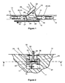
figure 2 est une vue en coupe transversale B-B des éléments de lafigure 1 , - la
figure 3 est une vue en coupe longitudinale horizontale C-C des éléments desfigures 1 et 2 , - les
figures 4 à 6 illustrent différentes séquences de fonctionnement du dispositif pousseur selon le premier mode de réalisation, - les
figures 7 à 9 illustrent différentes séquences de fonctionnement du dispositif pousseur selon un deuxième mode de réalisation - les
figures 10 et 11 illustrent un troisième mode de réalisation, - les
figures 12 et 13 représentent un quatrième mode de réalisation.
- the
figure 1 is a vertical longitudinal sectional view AA of part of the installation, in a first embodiment of the pusher device, during operation, - the
figure 2 is a cross-sectional view BB of the elements of thefigure 1 , - the
figure 3 is a horizontal longitudinal sectional view CC of the elements ofFigures 1 and 2 , - the
Figures 4 to 6 illustrate different operating sequences of the pusher device according to the first embodiment, - the
Figures 7 to 9 illustrate different operating sequences of the pusher device according to a second embodiment - the
Figures 10 and 11 illustrate a third embodiment, - the
Figures 12 and 13 represent a fourth embodiment.
Comme indiqué précédemment, l'invention concerne une installation mécanique permettant le transport d'une personne placée sur un véhicule léger et individuel de transport tel qu'une bicyclette ou analogue, comme par exemple une trottinette. L'installation comporte un moyen filaire d'entraînement 10, par exemple un câble ou une chaîne, agencé en une boucle fermée logée dans une lacune 11 aménagée dans le sol 12. La lacune 11 raccorde une zone de départ et une zone d'arrivée entre lesquelles l'installation réalise le transport des personnes. Le moyen filaire d'entraînement 10 est entraîné dans un mouvement de défilement entre les deux zones, de manière que l'un de ses brins aille de la zone de départ vers la zone d'arrivée (voir flèche 13). Il est possible de prévoir à cet effet un mécanisme de motorisation dans la zone d'arrivée et un mécanisme de mise en tension dans la zone de départ, ou inversement un mécanisme de motorisation dans la zone de départ et un mécanisme de mise en tension dans la zone d'arrivée. Il est également envisageable d'aménager dans la zone d'arrivée un mécanisme dédié à la fois à la motorisation et à la mise en tension, la zone de départ étant alors équipée d'un mécanisme de retour fixe.As indicated above, the invention relates to a mechanical installation for transporting a person placed on a light and individual transport vehicle such as a bicycle or the like, such as a scooter. The installation comprises a wire drive means 10, for example a cable or a chain, arranged in a closed loop housed in a
Au moins un dispositif pousseur, préférentiellement plusieurs répartis à intervalles réguliers, est accouplé au moyen filaire d'entraînement 10 pour assurer la propulsion d'un pied 14 de la personne pendant le déplacement du dispositif pousseur de la zone de départ vers la zone d'arrivée selon la flèche 13.At least one pusher device, preferably several distributed at regular intervals, is coupled to the
Conformément à l'invention, chaque dispositif pousseur comporte un chariot 15, une pédale de poussée 16, et un mécanisme de verrouillage décrit plus loin.According to the invention, each pusher device comprises a
Le chariot 15 est équipé d'une patte d'accrochage 17 aux moyen filaire d'entraînement 10 et de moyens de roulement associés à des moyens de guidage aménagés dans le sol 12 entre la zone de départ et la zone d'arrivée. La lacune 11 en forme de tranchée aménagée dans le sol entre les zones de départ et d'arrivée présente des formes adaptées pour recevoir le chariot 15. Les moyens de roulement comprennent une paire de galets horizontaux 18, 19 aménagés aux extrémités du chariot dans sa direction de déplacement, et deux paires de galets verticaux 20 à 23. La paire de galets verticaux 20, 21 est positionnée à proximité du galet horizontal 18 vers l'avant du chariot 15, tandis que paire de galets verticaux 22, 23 est positionnée à proximité du galet horizontal 19 vers l'arrière du chariot 15. Les galets horizontaux 18, 19 et verticaux 20 à 23 roulent dans deux rails latéraux 24, 25 bordant la lacune 11. Chaque rail latéral 24, 25 présente une section en forme de U, ouverte en direction du rail latéral 24, 25 opposé. Potentiellement, les rails 24, 25 peuvent présenter une courbure permettant au dispositif pousseur de se déplacer selon une trajectoire présentant des courbes symbolisées par le repère R sur la
La pédale de poussée 16 présente une face active 26 sur laquelle le pied 14 vient prendre appui pendant l'opération de propulsion débutant simultanément à l'opération de déplacement du dispositif pousseur de la zone de départ vers la zone d'arrivée. Dans le cas particulier illustré, la pédale de poussée 16 présente une forme triangulaire dans un plan longitudinal vertical et la face active 26 est constituée par le bord supérieur de ce triangle. Sur la face active 26, le pied 14 exerce un effort presseur F (
La pédale de poussée 16 est montée à pivotement sur le chariot 15 pour occuper sélectivement, pendant le déplacement du chariot 15 de la zone de départ vers la zone d'arrivée, soit une position en saillie du sol (
Un cliquet 29 est monté à pivotement sur la pédale de poussée 16 selon une articulation 30 située dans la partie supérieure de la pédale, c'est-à-dire en arrière et au-dessus de l'articulation 28. Le cliquet 29 est placé dans un logement central de la pédale 16 délimité par deux flancs latéraux de la pédale 16. Le cliquet présente sensiblement une forme d'arc de cercle et l'articulation 30 est aménagée sensiblement au milieu de l'arc. Il comporte un bord supérieur convexe tourné vers le haut, et un bord inférieur concave tourné vers le fond de la lacune 11 au travers de la lumière 27. À l'extrémité arrière du cliquet 29 est prévu un élément de blocage 31 aménagé en saillie longitudinalement par rapport au corps arqué du cliquet 29. Le bord supérieur convexe, notamment dans la partie du cliquet 29 en avant de l'articulation 30, a la possibilité de venir en saillie vers le dessus de la face active 26 de la pédale 13, par pivotement autour de l'articulation 30, au travers d'une fente 32 aménagée dans la face active 26 et débouchant sur le logement central de la pédale 16.A
Un ressort de rappel 33 à course rectiligne est fixé à une extrémité à la pédale 16 à un point de fixation légèrement en arrière de l'articulation 28, et à son extrémité opposée sur la partie de cliquet 29 située en arrière de l'articulation 30.A straight
La longueur du ressort de rappel 33 est choisie de manière à ce que dans sa configuration naturelle, il maintienne le cliquet 29 dans une position angulaire par rapport à la pédale de poussée 16, telle que la partie avant du bord supérieur convexe du cliquet 29 est en saillie de la face active 26 de la pédale 16. Lorsqu'un effort presseur F est appliqué sur la face active 26, cet effort F a pour effet de supprimer cette position en saillie par rapport à la face active 26, provoquant le pivotement du cliquet 29 par rapport à la pédale 16 autour de l'articulation 30 et le passage du ressort de rappel 33 vers une configuration déformée (en l'occurrence par allongement) élastiquement par rapport à sa configuration naturelle. Le retour naturel du ressort de rappel 33 vers sa configuration naturelle lorsque l'effort presseur F cesse provoque le retour du cliquet 29 dans une position angulaire par rapport à la pédale de poussée 16 telle que la partie avant du bord supérieur convexe du cliquet 29 est en saillie de la face active 26 de la pédale 16.The length of the
Le dispositif pousseur comporte en outre, par exemple solidaire du chariot 15, un élément de retenue 34 apte à coopérer, par contact mécanique direct, avec l'élément de blocage 31. Étant solidaire du chariot 15, l'élément de retenue 34 possède la propriété d'être fixe dans tout référentiel lié au dispositif pousseur. Au contraire, l'élément de blocage 31 peut être considéré comme mobile dans tout référentiel lié au dispositif pousseur, par pivotement du cliquet 29. Le positionnement relatif des éléments de blocage 31 et de retenue 34 est choisi de manière que:
- lorsque le ressort de rappel 33 est dans sa configuration naturelle, les éléments 31 et 34 ne peuvent pas venir en contact mécanique l'un avec l'autre quelle que soit la position angulaire de la pédale de poussée 16 par
rapport au chariot 15 autour de l'articulation 28, - et lorsque un effort presseur F est appliqué, créant un pivotement du cliquet 29 et une déformation élastique du ressort 30 par rapport à sa configuration naturelle, l'élément de blocage 31 subit un déplacement tel que les éléments 31 et 34 viennent automatiquement en contact l'un avec l'autre lorsque la pédale 16 a tendance a vouloir passer vers la position escamotée, obligeant celle-ci à rester dans sa position en saillie du sol.
- when the
return spring 33 is in its natural configuration, theelements thrust pedal 16 relative to thecarriage 15 aroundarticulation 28, - and when a pressing force F is applied, creating a pivoting of the
pawl 29 and an elastic deformation of thespring 30 with respect to its natural configuration, the lockingelement 31 undergoes a displacement such that theelements pedal 16 tends to move to the retracted position, forcing it to stay in its position protruding from the ground.
Le cliquet 29 muni de son élément mobile de blocage 31, avantageusement monté à pivotement par rapport à la pédale 16, constitue de ce fait un mécanisme de verrouillage dans lequel l'élément mobile de blocage 31 est apte à coopérer, par contact mécanique, avec un élément fixe de retenue solidaire du chariot 15, et occupant pendant le déplacement du chariot 15 de la zone de départ vers la zone d'arrivée, soit un état actif dans lequel les éléments de blocage 31 et de retenue 34 sont en contact l'un avec l'autre pour créer une liaison mécanique rigide entre la pédale 16 et le chariot 15 bloquant le pivotement de la pédale 15 dans la position en saillie du sol, soit un état inactif dans lequel le contact entre les éléments de blocage 31 et de retenue 34 est supprimé pour rompre ladite liaison mécanique, libérant le pivotement de la pédale 16 vers la position escamotée.The
De ce qui précède, on comprend d'autre part que le ressort de rappel 33 constitue des moyens permettant au mécanisme de verrouillage d'occuper automatiquement son état inactif en cas d'absence d'effort presseur appliqué sur la pédale 16 pendant le déplacement du chariot de la zone de départ vers la zone d'arrivée.From the foregoing, it is further understood that the
Il est clair que la conception du dispositif pousseur pourrait être modifiée en restant dans le cadre de l'invention, en prévoyant notamment que le cliquet soit articulé sur le chariot et que l'élément de retenue soit solidaire de la pédale de poussée. Dans une telle variante, le ressort de rappel serait fixé à une extrémité sur le chariot et à son extrémité opposée sur le cliquet.It is clear that the design of the pusher device could be modified within the scope of the invention, providing in particular that the pawl is articulated on the carriage and that the retaining element is integral with the thrust pedal. In such a variant, the return spring would be fixed at one end to the carriage and at its opposite end to the pawl.
Pour un fonctionnement correct du dispositif pousseur représenté aux
D'autre part, comme évoqué précédemment, la particularité du cliquet 29 de venir en saillie de la face active 26 dans la configuration naturelle du ressort de rappel 33 constitue des moyens pour mettre le mécanisme de verrouillage dans son état actif dans la zone de départ, ces moyens étant actionnés par l'application d'un effort presseur F sur la pédale 16 au passage du dispositif pousseur dans la zone de départ. Autrement dit, l'application d'un effort presseur F commande le passage vers l'état actif du mécanisme de verrouillage. Il est clair qu'il peut toutefois être envisagé de prévoir des moyens pour mettre le mécanisme de verrouillage dans son état actif directement en amont de la zone de départ dans le sens de déplacement du dispositif pousseur. Autrement dit, les moyens pour mettre le mécanisme de verrouillage dans son état actif seraient automatiquement actionnés par le passage du dispositif pousseur à un deuxième emplacement prédéterminé situé dans la zone de départ ou en amont de celle-ci dans le sens de déplacement du dispositif pousseur, ledit deuxième emplacement étant disposé en aval du premier emplacement. Dans ce cas, le passage vers l'état actif du mécanisme de verrouillage serait automatiquement réalisé avant toute éventuelle application postérieure d'un effort presseur F dans la zone de départ.On the other hand, as mentioned above, the particularity of the
Les différentes séquences de fonctionnement du dispositif pousseur qui se dégagent de ce qui précède sont représentées sur les
Préalablement à la
La
Le ressort de rappel 33 constitue donc des moyens élastiques de rappel aptes à déplacer l'élément de blocage 31 par rapport à l'élément de retenue 34, et susceptibles d'occuper soit une configuration naturelle dans laquelle les éléments 31, 34 ne sont pas en contact, soit une configuration déformée élastiquement par rapport à sa configuration naturelle et dans laquelle les éléments sont en contact. D'autres modes de déformation élastique pourraient être envisagés, tels que la torsion ou la compression.The
Dans l'exemple particulier décrit ci-dessus, le passage de la configuration naturelle à la configuration déformée du ressort de rappel 33 est commandé par les moyens pour mettre le mécanisme de verrouillage dans son état actif c'est-à-dire l'application d'un effort presseur F, tandis que le passage de la configuration déformée à la configuration naturelle résulte, en cas d'absence d'effort presseur F sur la pédale, de l'élasticité du ressort de rappel 33.In the particular example described above, the transition from the natural configuration to the deformed configuration of the
Pour assurer une sécurité maximale des moyens peuvent être prévus pour obturer au moins partiellement la lacune 11 pendant le déplacement du dispositif pousseur de la zone de départ vers la zone d'arrivée. A cet effet, des obturateurs 35, 36 peuvent être aménagés dans la partie supérieure de la lacune 11 au niveau de la surface du sol 12, à l'aide d'un mécanisme permettant de les déplacer latéralement l'un par rapport à l'autre, entre une position éloignée offrant accès à l'intérieur de la lacune 11, et une position rapprochée dans laquelle leurs bords distaux sont placés à un écartement tout juste suffisant pour permettre le déplacement longitudinal de la pédale de poussée 16. Le mécanisme peut inclure des moyens de rappel des obturateurs 35, 36 vers la position rapprochée, interposés soit entre les deux obturateurs, soit entre chacun des obturateurs et un flanc latéral vertical creusé dans le sol.To ensure maximum security means can be provided to at least partially close the
Les
Dans ce deuxième mode de réalisation de dispositif pousseur, le cliquet 29 est supprimé, mais l'élément fixe de retenue 34 est toujours présent à l'arrière de la pédale de poussée 16. Celle-ci est montée sur le chariot 15 selon une liaison mécanique assurant, indépendamment l'un de l'autre, un pivotement libre d'axe latéral horizontal et une translation libre de direction sensiblement longitudinale, de la pédale 16 par rapport au chariot 15. À titre d'exemple, la pédale peut incorporer une ouverture oblongue 37 à l'intérieur de laquelle un axe 38 solidaire du chariot 15 est monté. L'ouverture oblongue 37 est aménagée à l'emplacement de l'articulation 28 du premier mode de réalisation. Le ressort de rappel 33 à course rectiligne est fixé à une extrémité à un point de la pédale 16 en avant de l'ouverture oblongue 37, et à son extrémité opposée à un point du chariot 15 situé en avant de la pédale de poussée 16. L'élément de blocage 39, considéré comme faisant partie intégrante du mécanisme de verrouillage selon l'invention, est pour sa part constitué par l'extrémité arrière inférieure de la pédale de poussée.In this second embodiment of the pusher device, the
Il ressort donc que l'élément de blocage appartenant au mécanisme de verrouillage selon l'invention peut donc être solidaire d'un cliquet indépendant de la pédale 16 ou du chariot 15 comme c'était le cas dans le premier mode de réalisation, mais peut également être solidaire de la pédale 16 elle-même, ce qui est le cas pour ce deuxième mode de réalisation. Par une conception adaptée du mécanisme de verrouillage, il pourrait être envisagé de rendre l'élément de blocage solidaire du chariot 15. Dans ce cas, il faudrait prendre soin de prévoir l'élément de retenue solidaire de la pédale de poussée 16.It therefore emerges that the locking element belonging to the locking mechanism according to the invention can therefore be integral with a pawl independent of the pedal 16 or the
La longueur du ressort de rappel 33 est choisie de manière à ce que dans sa configuration naturelle, il maintienne la pédale 16 dans une position longitudinale par rapport au chariot 15 telle que l'élément de blocage 39 et l'élément de retenue 34 ne peuvent pas venir en contact mécanique l'un avec l'autre quelle que soit la position angulaire de la pédale de poussée 16 par rapport au chariot 15 autour de l'axe 38. Lorsqu'un effort presseur F est appliqué sur la face active 26, cet effort F a pour effet de provoquer un recul longitudinal de la pédale 16, vers l'arrière, par coulissement de l'axe 38 dans l'ouverture oblongue. Ce recul de la pédale 16 implique le passage du ressort de rappel 33 vers une configuration déformée (en l'occurrence par allongement) élastiquement par rapport à sa configuration naturelle et l'élément de blocage 39 subit un déplacement tel que les éléments 39 et 34 viennent automatiquement en contact l'un avec l'autre lorsque la pédale 16 a tendance a vouloir passer vers la position escamotée, obligeant celle-ci à rester dans sa position en saillie du sol. Le retour naturel du ressort de rappel 33 vers sa configuration naturelle lorsque l'effort presseur F cesse provoque le déplacement inverse de la pédale 16, libérant l'élément de blocage 39 par rapport à l'élément de retenue 34 en supprimant toute possibilité de contact entre les éléments 34, 39 quelle que soit la position angulaire de la pédale 16 par rapport au chariot 15.The length of the
Les différentes séquences de fonctionnement du dispositif pousseur qui se dégagent de ce qui précède sont représentées sur les
Préalablement à la
La
Enfin, de manière non représentée et quelle que soit la variante, la pédale de poussée peut comporte un châssis monté à pivotement sur le chariot selon une première direction et un volet d'appui monté à pivotement sur la partie supérieure du châssis selon une deuxième direction perpendiculaire à la première. Un tel montage a pour vocation de permettre au volet d'appui d'occuper soit une position sensiblement perpendiculaire au châssis dans laquelle elle peut assurer la propulsion d'un pied de la personne pendant le déplacement du dispositif pousseur de la zone de départ vers la zone d'arrivée, soit une position sensiblement parallèle au châssis pour permettre à la pédale de venir occuper sa position escamotée.Finally, in a manner not shown and whatever the variant, the thrust pedal may comprise a frame pivotally mounted on the carriage in a first direction and a bearing flap pivotally mounted on the upper part of the frame in a second direction. perpendicular to the first. Such an assembly is intended to allow the support flap to occupy a position substantially perpendicular to the frame in which it can ensure the propulsion of a foot of the person during movement of the pusher device from the starting area to the arrival zone, a position substantially parallel to the chassis to allow the pedal to come to occupy its retracted position.
En référence aux
Toutefois, il est possible de prévoir un mécanisme de verrouillage conçu de telle sorte que le contact mécanique entre l'élément de blocage et l'élément de retenue ne cesse pas dans l'état inactif. C'est par exemple le cas d'un mécanisme de verrouillage formé par la genouillère 42 des
Claims (8)
Applications Claiming Priority (1)
| Application Number | Priority Date | Filing Date | Title |
|---|---|---|---|
| FR0804695A FR2935331B1 (en) | 2008-08-26 | 2008-08-26 | MECHANICAL INSTALLATION FOR TRANSPORTING A PERSON ON A BICYCLE OR SIMILAR |
Publications (2)
| Publication Number | Publication Date |
|---|---|
| EP2159123A1 true EP2159123A1 (en) | 2010-03-03 |
| EP2159123B1 EP2159123B1 (en) | 2012-06-27 |
Family
ID=40459262
Family Applications (1)
| Application Number | Title | Priority Date | Filing Date |
|---|---|---|---|
| EP20090354034 Not-in-force EP2159123B1 (en) | 2008-08-26 | 2009-08-11 | Mechanical installation for transporting a person on a bicycle or similar |
Country Status (3)
| Country | Link |
|---|---|
| EP (1) | EP2159123B1 (en) |
| ES (1) | ES2390745T3 (en) |
| FR (1) | FR2935331B1 (en) |
Families Citing this family (1)
| Publication number | Priority date | Publication date | Assignee | Title |
|---|---|---|---|---|
| CN108058695A (en) * | 2017-12-19 | 2018-05-22 | 罗学中 | A kind of shifting vehicle device of shared bicycle |
Citations (2)
| Publication number | Priority date | Publication date | Assignee | Title |
|---|---|---|---|---|
| CA775898A (en) * | 1968-01-16 | Garbers Ernst | Arrangement for automating the release operation in a railroad marshalling yard | |
| US5566621A (en) | 1992-05-05 | 1996-10-22 | Wanvik; Jarle | Conveyor arrangement for rolling transport devices |
-
2008
- 2008-08-26 FR FR0804695A patent/FR2935331B1/en not_active Expired - Fee Related
-
2009
- 2009-08-11 EP EP20090354034 patent/EP2159123B1/en not_active Not-in-force
- 2009-08-11 ES ES09354034T patent/ES2390745T3/en active Active
Patent Citations (2)
| Publication number | Priority date | Publication date | Assignee | Title |
|---|---|---|---|---|
| CA775898A (en) * | 1968-01-16 | Garbers Ernst | Arrangement for automating the release operation in a railroad marshalling yard | |
| US5566621A (en) | 1992-05-05 | 1996-10-22 | Wanvik; Jarle | Conveyor arrangement for rolling transport devices |
Also Published As
| Publication number | Publication date |
|---|---|
| ES2390745T3 (en) | 2012-11-16 |
| EP2159123B1 (en) | 2012-06-27 |
| FR2935331A1 (en) | 2010-03-05 |
| FR2935331B1 (en) | 2010-09-17 |
Similar Documents
| Publication | Publication Date | Title |
|---|---|---|
| CA2783595C (en) | Separation element for a platform cabin including a crank mechanism for moving an opening | |
| FR2759408A1 (en) | GUIDING DEVICE FOR A SLIDING PANEL AND A LENS FOR SHUTTERING A BAY | |
| FR2842467A1 (en) | REAR BEARING SYSTEM FOR DISCOVERABLE VEHICLE WITH FOLDABLE RIGID ROOF | |
| FR2495068A1 (en) | OPENING ROOF FOR VEHICLE | |
| EP0723889A1 (en) | Vehicle seat slide | |
| BE1014506A3 (en) | Device with re-introduction component element. | |
| EP3798084A1 (en) | Step assembly for transport vehicle, vehicle equipped with same and method for implementing said vehicle | |
| CA2783523C (en) | Separating element for platform cabin with a crankshaft drive arrangement for moving an out opening | |
| FR2885329A1 (en) | Seat`s armrest for motor vehicle, has horizontal axle rotatively mounted around fixed vertical axle such that support arm in vertical position pivots around vertical axle in order to be placed in housing arranged in reserve of backrest | |
| FR2881998A1 (en) | Motor vehicle, has upper and lower carriages forming two main support points for sliding door, lower roller forming additional support point to door, and guide pin, forming temporary support point for door, located on inner side of door | |
| EP0055166B1 (en) | Mechanical drive chain or belt tensioning device | |
| EP2159123B1 (en) | Mechanical installation for transporting a person on a bicycle or similar | |
| EP2014864B1 (en) | Roller shutter comprising a stop device for limiting the rolling of the roller shutter in the roller shutter housing | |
| EP2694306B2 (en) | Glass roof having a sliding and tilting mobile panel | |
| CH652936A5 (en) | SECURITY FIXING FOR SKIING. | |
| FR2876959A1 (en) | OPENING DEVICE FOR MOTOR VEHICLE | |
| EP1420980B1 (en) | Method for controlling a vehicle elevator side rails and device therefor | |
| FR2764253A1 (en) | MOBILE STEP DEVICE FOR A MOTOR VEHICLE | |
| EP2072720A1 (en) | Device for blocking an opening using a mobile panel, with a locking ramp, and corresponding vehicle | |
| EP2042372A1 (en) | Tilting-sliding loading bed device for breakdown vehicle. | |
| EP1927718B1 (en) | Device limiting the opening of a screen and closing or sun-protection installation including such a device | |
| EP2299039B1 (en) | Device for locking and unlocking a garage door or similar | |
| EP1442969B1 (en) | Tracked vehicle with variable wheelbase | |
| FR2880842A1 (en) | Sliding side door for use in motor vehicle, has step plate mounted on mobile support unit to act as support when door is in open position, where step plate and unit are inside body shell of vehicle when door is in closed position | |
| EP0034965A1 (en) | Actuating device for a sliding panel |
Legal Events
| Date | Code | Title | Description |
|---|---|---|---|
| PUAI | Public reference made under article 153(3) epc to a published international application that has entered the european phase |
Free format text: ORIGINAL CODE: 0009012 |
|
| AK | Designated contracting states |
Kind code of ref document: A1 Designated state(s): AT BE BG CH CY CZ DE DK EE ES FI FR GB GR HR HU IE IS IT LI LT LU LV MC MK MT NL NO PL PT RO SE SI SK SM TR |
|
| AX | Request for extension of the european patent |
Extension state: AL BA RS |
|
| 17P | Request for examination filed |
Effective date: 20100826 |
|
| 17Q | First examination report despatched |
Effective date: 20100930 |
|
| GRAP | Despatch of communication of intention to grant a patent |
Free format text: ORIGINAL CODE: EPIDOSNIGR1 |
|
| GRAS | Grant fee paid |
Free format text: ORIGINAL CODE: EPIDOSNIGR3 |
|
| GRAA | (expected) grant |
Free format text: ORIGINAL CODE: 0009210 |
|
| AK | Designated contracting states |
Kind code of ref document: B1 Designated state(s): AT BE BG CH CY CZ DE DK EE ES FI FR GB GR HR HU IE IS IT LI LT LU LV MC MK MT NL NO PL PT RO SE SI SK SM TR |
|
| REG | Reference to a national code |
Ref country code: GB Ref legal event code: FG4D Free format text: NOT ENGLISH |
|
| REG | Reference to a national code |
Ref country code: CH Ref legal event code: EP |
|
| REG | Reference to a national code |
Ref country code: AT Ref legal event code: REF Ref document number: 564013 Country of ref document: AT Kind code of ref document: T Effective date: 20120715 |
|
| REG | Reference to a national code |
Ref country code: IE Ref legal event code: FG4D Free format text: LANGUAGE OF EP DOCUMENT: FRENCH |
|
| REG | Reference to a national code |
Ref country code: DE Ref legal event code: R096 Ref document number: 602009007877 Country of ref document: DE Effective date: 20120823 |
|
| PG25 | Lapsed in a contracting state [announced via postgrant information from national office to epo] |
Ref country code: SE Free format text: LAPSE BECAUSE OF FAILURE TO SUBMIT A TRANSLATION OF THE DESCRIPTION OR TO PAY THE FEE WITHIN THE PRESCRIBED TIME-LIMIT Effective date: 20120627 Ref country code: NO Free format text: LAPSE BECAUSE OF FAILURE TO SUBMIT A TRANSLATION OF THE DESCRIPTION OR TO PAY THE FEE WITHIN THE PRESCRIBED TIME-LIMIT Effective date: 20120927 Ref country code: FI Free format text: LAPSE BECAUSE OF FAILURE TO SUBMIT A TRANSLATION OF THE DESCRIPTION OR TO PAY THE FEE WITHIN THE PRESCRIBED TIME-LIMIT Effective date: 20120627 Ref country code: LT Free format text: LAPSE BECAUSE OF FAILURE TO SUBMIT A TRANSLATION OF THE DESCRIPTION OR TO PAY THE FEE WITHIN THE PRESCRIBED TIME-LIMIT Effective date: 20120627 |
|
| REG | Reference to a national code |
Ref country code: CH Ref legal event code: NV Representative=s name: CABINET ROLAND NITHARDT CONSEILS EN PROPRIETE INDU |
|
| REG | Reference to a national code |
Ref country code: NL Ref legal event code: VDEP Effective date: 20120627 |
|
| REG | Reference to a national code |
Ref country code: ES Ref legal event code: FG2A Ref document number: 2390745 Country of ref document: ES Kind code of ref document: T3 Effective date: 20121116 |
|
| REG | Reference to a national code |
Ref country code: LT Ref legal event code: MG4D Effective date: 20120627 |
|
| PG25 | Lapsed in a contracting state [announced via postgrant information from national office to epo] |
Ref country code: GR Free format text: LAPSE BECAUSE OF FAILURE TO SUBMIT A TRANSLATION OF THE DESCRIPTION OR TO PAY THE FEE WITHIN THE PRESCRIBED TIME-LIMIT Effective date: 20120928 Ref country code: LV Free format text: LAPSE BECAUSE OF FAILURE TO SUBMIT A TRANSLATION OF THE DESCRIPTION OR TO PAY THE FEE WITHIN THE PRESCRIBED TIME-LIMIT Effective date: 20120627 Ref country code: SI Free format text: LAPSE BECAUSE OF FAILURE TO SUBMIT A TRANSLATION OF THE DESCRIPTION OR TO PAY THE FEE WITHIN THE PRESCRIBED TIME-LIMIT Effective date: 20120627 Ref country code: HR Free format text: LAPSE BECAUSE OF FAILURE TO SUBMIT A TRANSLATION OF THE DESCRIPTION OR TO PAY THE FEE WITHIN THE PRESCRIBED TIME-LIMIT Effective date: 20120627 |
|
| PG25 | Lapsed in a contracting state [announced via postgrant information from national office to epo] |
Ref country code: SK Free format text: LAPSE BECAUSE OF FAILURE TO SUBMIT A TRANSLATION OF THE DESCRIPTION OR TO PAY THE FEE WITHIN THE PRESCRIBED TIME-LIMIT Effective date: 20120627 Ref country code: CZ Free format text: LAPSE BECAUSE OF FAILURE TO SUBMIT A TRANSLATION OF THE DESCRIPTION OR TO PAY THE FEE WITHIN THE PRESCRIBED TIME-LIMIT Effective date: 20120627 Ref country code: RO Free format text: LAPSE BECAUSE OF FAILURE TO SUBMIT A TRANSLATION OF THE DESCRIPTION OR TO PAY THE FEE WITHIN THE PRESCRIBED TIME-LIMIT Effective date: 20120627 Ref country code: EE Free format text: LAPSE BECAUSE OF FAILURE TO SUBMIT A TRANSLATION OF THE DESCRIPTION OR TO PAY THE FEE WITHIN THE PRESCRIBED TIME-LIMIT Effective date: 20120627 Ref country code: CY Free format text: LAPSE BECAUSE OF FAILURE TO SUBMIT A TRANSLATION OF THE DESCRIPTION OR TO PAY THE FEE WITHIN THE PRESCRIBED TIME-LIMIT Effective date: 20120627 Ref country code: IS Free format text: LAPSE BECAUSE OF FAILURE TO SUBMIT A TRANSLATION OF THE DESCRIPTION OR TO PAY THE FEE WITHIN THE PRESCRIBED TIME-LIMIT Effective date: 20121027 |
|
| BERE | Be: lapsed |
Owner name: POMAGALSKI Effective date: 20120831 |
|
| PG25 | Lapsed in a contracting state [announced via postgrant information from national office to epo] |
Ref country code: PL Free format text: LAPSE BECAUSE OF FAILURE TO SUBMIT A TRANSLATION OF THE DESCRIPTION OR TO PAY THE FEE WITHIN THE PRESCRIBED TIME-LIMIT Effective date: 20120627 Ref country code: PT Free format text: LAPSE BECAUSE OF FAILURE TO SUBMIT A TRANSLATION OF THE DESCRIPTION OR TO PAY THE FEE WITHIN THE PRESCRIBED TIME-LIMIT Effective date: 20121029 |
|
| PG25 | Lapsed in a contracting state [announced via postgrant information from national office to epo] |
Ref country code: NL Free format text: LAPSE BECAUSE OF FAILURE TO SUBMIT A TRANSLATION OF THE DESCRIPTION OR TO PAY THE FEE WITHIN THE PRESCRIBED TIME-LIMIT Effective date: 20120627 Ref country code: MC Free format text: LAPSE BECAUSE OF NON-PAYMENT OF DUE FEES Effective date: 20120831 |
|
| PG25 | Lapsed in a contracting state [announced via postgrant information from national office to epo] |
Ref country code: DK Free format text: LAPSE BECAUSE OF FAILURE TO SUBMIT A TRANSLATION OF THE DESCRIPTION OR TO PAY THE FEE WITHIN THE PRESCRIBED TIME-LIMIT Effective date: 20120627 |
|
| PLBE | No opposition filed within time limit |
Free format text: ORIGINAL CODE: 0009261 |
|
| STAA | Information on the status of an ep patent application or granted ep patent |
Free format text: STATUS: NO OPPOSITION FILED WITHIN TIME LIMIT |
|
| REG | Reference to a national code |
Ref country code: IE Ref legal event code: MM4A |
|
| PG25 | Lapsed in a contracting state [announced via postgrant information from national office to epo] |
Ref country code: BE Free format text: LAPSE BECAUSE OF NON-PAYMENT OF DUE FEES Effective date: 20120831 |
|
| 26N | No opposition filed |
Effective date: 20130328 |
|
| REG | Reference to a national code |
Ref country code: DE Ref legal event code: R097 Ref document number: 602009007877 Country of ref document: DE Effective date: 20130328 |
|
| PG25 | Lapsed in a contracting state [announced via postgrant information from national office to epo] |
Ref country code: BG Free format text: LAPSE BECAUSE OF FAILURE TO SUBMIT A TRANSLATION OF THE DESCRIPTION OR TO PAY THE FEE WITHIN THE PRESCRIBED TIME-LIMIT Effective date: 20120927 Ref country code: IE Free format text: LAPSE BECAUSE OF NON-PAYMENT OF DUE FEES Effective date: 20120811 |
|
| PG25 | Lapsed in a contracting state [announced via postgrant information from national office to epo] |
Ref country code: MT Free format text: LAPSE BECAUSE OF FAILURE TO SUBMIT A TRANSLATION OF THE DESCRIPTION OR TO PAY THE FEE WITHIN THE PRESCRIBED TIME-LIMIT Effective date: 20120627 |
|
| GBPC | Gb: european patent ceased through non-payment of renewal fee |
Effective date: 20130811 |
|
| PG25 | Lapsed in a contracting state [announced via postgrant information from national office to epo] |
Ref country code: TR Free format text: LAPSE BECAUSE OF FAILURE TO SUBMIT A TRANSLATION OF THE DESCRIPTION OR TO PAY THE FEE WITHIN THE PRESCRIBED TIME-LIMIT Effective date: 20120627 |
|
| PG25 | Lapsed in a contracting state [announced via postgrant information from national office to epo] |
Ref country code: LU Free format text: LAPSE BECAUSE OF NON-PAYMENT OF DUE FEES Effective date: 20120811 Ref country code: SM Free format text: LAPSE BECAUSE OF FAILURE TO SUBMIT A TRANSLATION OF THE DESCRIPTION OR TO PAY THE FEE WITHIN THE PRESCRIBED TIME-LIMIT Effective date: 20120627 |
|
| PG25 | Lapsed in a contracting state [announced via postgrant information from national office to epo] |
Ref country code: GB Free format text: LAPSE BECAUSE OF NON-PAYMENT OF DUE FEES Effective date: 20130811 Ref country code: HU Free format text: LAPSE BECAUSE OF FAILURE TO SUBMIT A TRANSLATION OF THE DESCRIPTION OR TO PAY THE FEE WITHIN THE PRESCRIBED TIME-LIMIT Effective date: 20090811 |
|
| PG25 | Lapsed in a contracting state [announced via postgrant information from national office to epo] |
Ref country code: MK Free format text: LAPSE BECAUSE OF FAILURE TO SUBMIT A TRANSLATION OF THE DESCRIPTION OR TO PAY THE FEE WITHIN THE PRESCRIBED TIME-LIMIT Effective date: 20120627 |
|
| REG | Reference to a national code |
Ref country code: FR Ref legal event code: PLFP Year of fee payment: 8 |
|
| REG | Reference to a national code |
Ref country code: FR Ref legal event code: PLFP Year of fee payment: 9 |
|
| REG | Reference to a national code |
Ref country code: FR Ref legal event code: PLFP Year of fee payment: 10 |
|
| PGFP | Annual fee paid to national office [announced via postgrant information from national office to epo] |
Ref country code: ES Payment date: 20200923 Year of fee payment: 12 Ref country code: FR Payment date: 20200824 Year of fee payment: 12 Ref country code: DE Payment date: 20200827 Year of fee payment: 12 |
|
| PGFP | Annual fee paid to national office [announced via postgrant information from national office to epo] |
Ref country code: CH Payment date: 20200821 Year of fee payment: 12 Ref country code: AT Payment date: 20200820 Year of fee payment: 12 Ref country code: IT Payment date: 20200806 Year of fee payment: 12 |
|
| REG | Reference to a national code |
Ref country code: DE Ref legal event code: R119 Ref document number: 602009007877 Country of ref document: DE |
|
| REG | Reference to a national code |
Ref country code: CH Ref legal event code: PL |
|
| REG | Reference to a national code |
Ref country code: AT Ref legal event code: MM01 Ref document number: 564013 Country of ref document: AT Kind code of ref document: T Effective date: 20210811 |
|
| PG25 | Lapsed in a contracting state [announced via postgrant information from national office to epo] |
Ref country code: LI Free format text: LAPSE BECAUSE OF NON-PAYMENT OF DUE FEES Effective date: 20210831 Ref country code: CH Free format text: LAPSE BECAUSE OF NON-PAYMENT OF DUE FEES Effective date: 20210831 Ref country code: AT Free format text: LAPSE BECAUSE OF NON-PAYMENT OF DUE FEES Effective date: 20210811 |
|
| PG25 | Lapsed in a contracting state [announced via postgrant information from national office to epo] |
Ref country code: IT Free format text: LAPSE BECAUSE OF NON-PAYMENT OF DUE FEES Effective date: 20210811 Ref country code: FR Free format text: LAPSE BECAUSE OF NON-PAYMENT OF DUE FEES Effective date: 20210831 Ref country code: DE Free format text: LAPSE BECAUSE OF NON-PAYMENT OF DUE FEES Effective date: 20220301 |
|
| REG | Reference to a national code |
Ref country code: ES Ref legal event code: FD2A Effective date: 20221102 |
|
| PG25 | Lapsed in a contracting state [announced via postgrant information from national office to epo] |
Ref country code: ES Free format text: LAPSE BECAUSE OF NON-PAYMENT OF DUE FEES Effective date: 20210812 |