EP2159109A1 - Reinforcement with channel design - Google Patents
Reinforcement with channel design Download PDFInfo
- Publication number
- EP2159109A1 EP2159109A1 EP08163414A EP08163414A EP2159109A1 EP 2159109 A1 EP2159109 A1 EP 2159109A1 EP 08163414 A EP08163414 A EP 08163414A EP 08163414 A EP08163414 A EP 08163414A EP 2159109 A1 EP2159109 A1 EP 2159109A1
- Authority
- EP
- European Patent Office
- Prior art keywords
- material layer
- reinforcement
- set forth
- exterior walls
- carrier
- Prior art date
- Legal status (The legal status is an assumption and is not a legal conclusion. Google has not performed a legal analysis and makes no representation as to the accuracy of the status listed.)
- Withdrawn
Links
- 230000002787 reinforcement Effects 0.000 title claims abstract description 35
- 239000000463 material Substances 0.000 claims abstract description 93
- 238000004070 electrodeposition Methods 0.000 claims abstract description 22
- 230000001070 adhesive effect Effects 0.000 claims description 9
- 239000000853 adhesive Substances 0.000 claims description 8
- 239000006260 foam Substances 0.000 claims description 8
- 238000001125 extrusion Methods 0.000 claims description 5
- 239000004616 structural foam Substances 0.000 claims description 4
- 238000000034 method Methods 0.000 description 12
- 238000013459 approach Methods 0.000 description 4
- 239000002184 metal Substances 0.000 description 3
- 239000004033 plastic Substances 0.000 description 3
- 238000005260 corrosion Methods 0.000 description 2
- 230000007797 corrosion Effects 0.000 description 2
- 239000003973 paint Substances 0.000 description 2
- 238000007789 sealing Methods 0.000 description 2
- 230000003466 anti-cipated effect Effects 0.000 description 1
- 239000000969 carrier Substances 0.000 description 1
- 238000010276 construction Methods 0.000 description 1
- 239000000109 continuous material Substances 0.000 description 1
- 230000003247 decreasing effect Effects 0.000 description 1
- 230000001419 dependent effect Effects 0.000 description 1
- 238000011161 development Methods 0.000 description 1
- 230000018109 developmental process Effects 0.000 description 1
- 239000000428 dust Substances 0.000 description 1
- 238000004519 manufacturing process Methods 0.000 description 1
- 238000012986 modification Methods 0.000 description 1
- 230000004048 modification Effects 0.000 description 1
- 238000005507 spraying Methods 0.000 description 1
Images


Classifications
-
- B—PERFORMING OPERATIONS; TRANSPORTING
- B60—VEHICLES IN GENERAL
- B60R—VEHICLES, VEHICLE FITTINGS, OR VEHICLE PARTS, NOT OTHERWISE PROVIDED FOR
- B60R13/00—Elements for body-finishing, identifying, or decorating; Arrangements or adaptations for advertising purposes
- B60R13/08—Insulating elements, e.g. for sound insulation
-
- B—PERFORMING OPERATIONS; TRANSPORTING
- B60—VEHICLES IN GENERAL
- B60R—VEHICLES, VEHICLE FITTINGS, OR VEHICLE PARTS, NOT OTHERWISE PROVIDED FOR
- B60R13/00—Elements for body-finishing, identifying, or decorating; Arrangements or adaptations for advertising purposes
-
- B—PERFORMING OPERATIONS; TRANSPORTING
- B62—LAND VEHICLES FOR TRAVELLING OTHERWISE THAN ON RAILS
- B62D—MOTOR VEHICLES; TRAILERS
- B62D29/00—Superstructures, understructures, or sub-units thereof, characterised by the material thereof
-
- B—PERFORMING OPERATIONS; TRANSPORTING
- B62—LAND VEHICLES FOR TRAVELLING OTHERWISE THAN ON RAILS
- B62D—MOTOR VEHICLES; TRAILERS
- B62D29/00—Superstructures, understructures, or sub-units thereof, characterised by the material thereof
- B62D29/001—Superstructures, understructures, or sub-units thereof, characterised by the material thereof characterised by combining metal and synthetic material
- B62D29/002—Superstructures, understructures, or sub-units thereof, characterised by the material thereof characterised by combining metal and synthetic material a foamable synthetic material or metal being added in situ
-
- B—PERFORMING OPERATIONS; TRANSPORTING
- B62—LAND VEHICLES FOR TRAVELLING OTHERWISE THAN ON RAILS
- B62D—MOTOR VEHICLES; TRAILERS
- B62D29/00—Superstructures, understructures, or sub-units thereof, characterised by the material thereof
- B62D29/001—Superstructures, understructures, or sub-units thereof, characterised by the material thereof characterised by combining metal and synthetic material
- B62D29/004—Superstructures, understructures, or sub-units thereof, characterised by the material thereof characterised by combining metal and synthetic material the metal being over-moulded by the synthetic material, e.g. in a mould
-
- Y—GENERAL TAGGING OF NEW TECHNOLOGICAL DEVELOPMENTS; GENERAL TAGGING OF CROSS-SECTIONAL TECHNOLOGIES SPANNING OVER SEVERAL SECTIONS OF THE IPC; TECHNICAL SUBJECTS COVERED BY FORMER USPC CROSS-REFERENCE ART COLLECTIONS [XRACs] AND DIGESTS
- Y10—TECHNICAL SUBJECTS COVERED BY FORMER USPC
- Y10T—TECHNICAL SUBJECTS COVERED BY FORMER US CLASSIFICATION
- Y10T428/00—Stock material or miscellaneous articles
- Y10T428/13—Hollow or container type article [e.g., tube, vase, etc.]
Definitions
- Reinforcements are used in various industries to provide structural support to or reduce noise and/or vibrations in various products.
- the reinforcement may be used to reinforce beams, pillars, rails, nodes, doors, or roof of the vehicle.
- the reinforcement may include a carrier disposed in a cavity of the product, and a material layer, such as structural or acoustic foam or an adhesive, is disposed on the carrier.
- the carrier may be made from plastic or metal bonded with the material layer. Accordingly, the material layer generally has adhesive properties.
- the carrier includes an array of ribs.
- the material layer is applied around the carrier in a way that a gap between the carrier and the cavity remains free to electrocoating flow.
- the size of the gap greatly impacts the effectiveness of the electrocoating process. For example, if the gap is too large and the material layer is relatively thick, the global mechanical performance of the carrier is decreased. For example, the gap may be 6 to 10 mm and partially filled with the unexpanded material layer, which may have lower performance due to a weak bonding between the carrier and the product to be reinforced. If the gap is too small (0 to 4 mm), the electrocoating will not effectively protect against corrosion of the product because there is not enough room for an electrocoating material to flow. Therefore, a reinforcement is needed that allows for effective electrocoating with a smaller or no gaps between the carrier and the product.
- a reinforcement includes a carrier having a plurality of exterior walls spaced from one another and defining a channel extending substantially parallel to a longitudinal axis defined by a cavity.
- a material layer is disposed on at least one of the exterior walls within the channel such that an electrocoating material is able to flow through the channel before the material layer is expanded and the channel is substantially filled after the material layer is expanded. Accordingly, gaps between the carrier and an object to be reinforced may be reduced or eliminated without substantially affecting the electrocoating process.
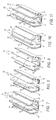
- Figure 1 is an illustration of a carrier disposed within a cavity having exterior walls and longitudinal ribs with a material layer disposed thereon and defining multiple channels, according to an embodiment
- Figure 2 is an illustration of the carrier of Figure 1 where the material layer has been expanded to fill the channel, according to an embodiment
- Figure 3 is an illustration of the carrier having transverse ribs, according to an embodiment
- Figure 4 is an illustration of the carrier where the material layer is continuous in a longitudinal direction, according to an embodiment
- Figure 5 is an illustration of the carrier where the material layer is discontinuous in a longitudinal direction, according to an embodiment
- Figure 6 is an illustration of the carrier where the material layer is discontinuous and alternative, according to an embodiment
- Figure 7 is an illustration of the carrier where the material layer is continuous in a transverse direction and disposed on the exterior walls and longitudinal ribs, according to an embodiment
- Figure 8 is an illustration of the carrier where the material layer is continuous in a transverse direction and disposed on the exterior walls and one of the longitudinal ribs, according to an embodiment
- Figure 9 is an illustration of the carrier where the material layer is disposed on a base of the carrier, according to an embodiment
- Figure 10 is an illustration of the carrier where the material layer extends between the exterior walls and the longitudinal ribs and between the longitudinal ribs spaced from the base, according to an embodiment
- Figure 11 is an illustration of the carrier where the material layer is disposed on the exterior walls, the longitudinal ribs, and the base.
- a reinforcement includes a carrier having a plurality of exterior walls spaced from one another.
- the carrier defines a channel extending substantially parallel to a longitudinal axis defined by a cavity.
- a material layer is disposed on at least one of the exterior walls within the channel such that an electrocoating material is able to flow through the channel before the material layer is expanded and the channel is substantially filled after the material layer is expanded.
- removing transverse ribs from the carrier creates new flow channels for the electrocoating process, and the material layer interconnects the longitudinal ribs after expansion in the baking process.
- the carrier may include transverse ribs that provide additional support to the carrier, but do not interfere with the electrocoating process.
- Figure 1 illustrates an exemplary reinforcement having a carrier 10 with a plurality of exterior walls 12 spaced from one another and connected by a base 14.
- the carrier 10 may be formed of any material, such as metal, plastic, or a hybrid of plastic and metal, and is disposed in a cavity of an object 16 to be reinforced.
- the cavity defines a longitudinal axis A
- the carrier 10 defines at least one channel 18 extending substantially parallel to the longitudinal axis A .
- the channel 18 may have any length relative to the carrier 10.
- the channel length along the longitudinal axis A may be longer than a width of the carrier 10 transverse to the longitudinal axis A , or alternatively, the channel 18 may be shorter along the longitudinal axis A than it is wide.
- the carrier 10 may include a plurality of longitudinal ribs 20 spaced from the exterior walls 12.
- the longitudinal ribs 20 extend in a direction substantially parallel to the exterior walls 12 and the longitudinal axis A .
- multiple channels 18 are defined by the longitudinal ribs 20 and/or the exterior walls 12.
- a material layer 22 may include acoustic foam, structural foam, and/or an adhesive disposed onto at least one of the exterior walls 12 and/or at least one of the longitudinal ribs 20 within the channel 18.
- the material layer 22 may be over-molded or beaded onto the carrier 10.
- the material layer 22 may be mechanically attached with pins, hooks, or other fittings.
- the material layer 22 may be disposed on an inner surface and/or outer surface of the exterior walls 12.
- the material layer 22 may expand or cure when subject to heat. For example, if the material layer 22 includes structural or acoustic foam used in a vehicle pillar, the foam may expand when in the paint bake process.
- the material layer 22 includes the adhesive
- the adhesive will cure during the paint bake process.
- the material layer 22 expands to fill the channel 18 and interconnect the longitudinal ribs 20 and the exterior walls 12. It is to be appreciated that the material layer 22 need not expand to completely fill the channel 18 and the amount of expansion needed is dependent upon the amount of loading on the carrier 10.
- the material layer 22 may include acoustic foam that expands to fill the entire channel 18 instead of structural foam that may not expand to fill the entire channel 18. It is to be appreciated that in other situations, structural foam may be replaced with acoustic foam to provide acoustic sealing or sealing against gas, dust, and humidity.
- the object 16 to be reinforced may be subject to an electrocoating process to reduce corrosion.
- the gap may be completely filled by the adhesive squeezed into the gap.
- additional adhesive may be squeezed into the gap once the material layer 22 has expanded to at least partially fill the gap.
- the electrocoating process may include spraying an electrocoating material onto the object 16 in a direction substantially parallel to the longitudinal axis A through the channel 18 and/or the gap.
- the carrier 10 is configured so that the electrocoating material is able to flow through the channel 18 before the material layer 22 is expanded.
- the material layer 22 may be disposed within the channel 18 prior to the electrocoating process, but does not substantially interfere with the flow of the electrocoating material through the channel 18.
- Figure 2 illustrates the material layer 22 including acoustic foam that has expanded to fill the channel 18 after the electrocoating material has been applied to the reinforced object 14.
- Figure 3 illustrates an exemplary embodiment of the reinforcement where the carrier 10 includes a plurality of transverse ribs 24 extending in a direction transverse to the exterior walls 12, the longitudinal ribs 20, and the longitudinal axis A .
- the transverse ribs 24 extend in a direction transverse to the electrocoating direction.
- the transverse ribs 24 may help prevent buckling of the longitudinal ribs 20.
- the material layer 22 may be at least partially disposed on at least one of the transverse ribs 24. Accordingly, the transverse ribs 24 extend in a direction transverse to the channel 18.
- the transverse ribs 24 may be shorter than the longitudinal ribs 20 and/or the exterior walls 12. In one exemplary approach, the transverse ribs 24 have less than 80% of cross-sectional area of the cavity. As illustrated in Figure 3 , the transverse ribs 24 may have a U-shaped opening or any other configuration. In one embodiment, the transverse ribs 24 may define holes and/or cuts to allow the electrocoating material to pass. For example, the channel 18 may be defined by holes formed in the transverse ribs 24.
- Figures 4-11 illustrate an embodiment of the reinforcement having two exterior walls 12 extending at an angle ⁇ from the base 14 of the carrier 10.
- Two longitudinal ribs 20 extend perpendicularly from the base 14.
- the carrier 10 defines three channels 18. Specifically, two channels 18 are defined by one of the exterior walls 12 and one of the longitudinal ribs 20. The third channel 18 is defined by the two longitudinal ribs 20.
- the carriers 10 of Figures 4-11 may include one or more transverse ribs 24.
- the material layer 22 is disposed on inner and outer surfaces of each of the exterior walls 12, on an outer surface of the base 14, and on inner surfaces of each of the longitudinal ribs 20 in a longitudinal direction.
- the material layer 22 is continuous along the longitudinal ribs 20 and the exterior walls 12, which means that the material layer 22 is constant in geometry.
- the material layer 22 may be a rectangular, trapezoidal, square, triangular, circular, or any other shape or cross-sectional configuration. Continuous material layers 22 may be produced by extrusion. In the case of complete uniform sections to be reinforced, the carrier 10 by itself or the carrier 10 with the material layer 22 could be produced by extrusion or co-extrusion.
- the material layer 22 is discontinuous, which means that the material layer 22 is divided into sections with spaces therebetween, along the longitudinal ribs 20 and the exterior walls 12. This variable configuration may provide variable final density and local mechanical properties. Moreover, in this embodiment, the material layer 22 could also provide support in buckling areas, and specifically, buckling areas on the longitudinal ribs 20. In one embodiment, the material layer 22 could be linked with material channels 18 to facilitate the manufacturing. In Figure 5 , the material layer 22 disposed on the longitudinal ribs 20 is alternative or staggered compared to the material layer 22 on the inner surface of the exterior walls 12.
- the material layer 22 is disposed on the carrier 10 in a transverse direction and in different configurations or placed on various surfaces of each of the walls or ribs. Although illustrated as being continuous, in another embodiment, the material layer 22 may be discontinuous or discontinuous and alternative.
- the material layer 22 is disposed on the inner and outer surfaces of the exterior walls 12 and longitudinal ribs 20.
- the material layer 22 is also disposed on the outer surface of the base 14.
- the material layer 22 is disposed on the inner surface of one of the longitudinal ribs 20, the outer surface of the base 14, and the inner and outer surfaces of the exterior walls 12.
- the material layer 22 is disposed on the inner and outer surfaces of the base 14, and the outer surface of the exterior walls 12.
- the material layer 22 is disposed on the outer surfaces of the base 14 and exterior walls 12, and further extends between each of the exterior walls 12 to one of the longitudinal ribs 20 spaced from the base 14. Also, the material layer 22 extends between the longitudinal ribs 20 spaced from the base 14. In Figure 11 , the material layer 22 is disposed on the inner and outer surfaces of the exterior walls 12, the base 14, and the longitudinal ribs 20. Although not illustrated, the embodiments of Figures 7-11 may further include transverse ribs 24 as previously described.
Landscapes
- Engineering & Computer Science (AREA)
- Mechanical Engineering (AREA)
- Chemical & Material Sciences (AREA)
- Structural Engineering (AREA)
- Combustion & Propulsion (AREA)
- Transportation (AREA)
- Architecture (AREA)
- Physics & Mathematics (AREA)
- Acoustics & Sound (AREA)
- Body Structure For Vehicles (AREA)
- Building Environments (AREA)
- Laminated Bodies (AREA)
- Finishing Walls (AREA)
Abstract
A reinforcement includes a carrier having a plurality of exterior walls spaced from one another. The carrier defines a channel extending substantially parallel to a longitudinal axis defined by a cavity. A material layer is disposed on at least one of the exterior walls within the channel such that an electrocoating material is able to flow through the channel before the material layer is expanded and the channel is substantially filled after the material layer is expanded.
Description
- Reinforcements are used in various industries to provide structural support to or reduce noise and/or vibrations in various products. For example, in the automotive industry, the reinforcement may be used to reinforce beams, pillars, rails, nodes, doors, or roof of the vehicle. The reinforcement may include a carrier disposed in a cavity of the product, and a material layer, such as structural or acoustic foam or an adhesive, is disposed on the carrier. The carrier may be made from plastic or metal bonded with the material layer. Accordingly, the material layer generally has adhesive properties.
- Sometimes, the carrier includes an array of ribs. The material layer is applied around the carrier in a way that a gap between the carrier and the cavity remains free to electrocoating flow. The size of the gap greatly impacts the effectiveness of the electrocoating process. For example, if the gap is too large and the material layer is relatively thick, the global mechanical performance of the carrier is decreased. For example, the gap may be 6 to 10 mm and partially filled with the unexpanded material layer, which may have lower performance due to a weak bonding between the carrier and the product to be reinforced. If the gap is too small (0 to 4 mm), the electrocoating will not effectively protect against corrosion of the product because there is not enough room for an electrocoating material to flow. Therefore, a reinforcement is needed that allows for effective electrocoating with a smaller or no gaps between the carrier and the product.
- A reinforcement includes a carrier having a plurality of exterior walls spaced from one another and defining a channel extending substantially parallel to a longitudinal axis defined by a cavity. A material layer is disposed on at least one of the exterior walls within the channel such that an electrocoating material is able to flow through the channel before the material layer is expanded and the channel is substantially filled after the material layer is expanded. Accordingly, gaps between the carrier and an object to be reinforced may be reduced or eliminated without substantially affecting the electrocoating process.
- The foregoing description will be understood more completely from the following detailed description of the exemplary drawings, in which:
-
Figure 1 is an illustration of a carrier disposed within a cavity having exterior walls and longitudinal ribs with a material layer disposed thereon and defining multiple channels, according to an embodiment; -
Figure 2 is an illustration of the carrier ofFigure 1 where the material layer has been expanded to fill the channel, according to an embodiment; -
Figure 3 is an illustration of the carrier having transverse ribs, according to an embodiment; -
Figure 4 is an illustration of the carrier where the material layer is continuous in a longitudinal direction, according to an embodiment; -
Figure 5 is an illustration of the carrier where the material layer is discontinuous in a longitudinal direction, according to an embodiment; -
Figure 6 is an illustration of the carrier where the material layer is discontinuous and alternative, according to an embodiment; -
Figure 7 is an illustration of the carrier where the material layer is continuous in a transverse direction and disposed on the exterior walls and longitudinal ribs, according to an embodiment; -
Figure 8 is an illustration of the carrier where the material layer is continuous in a transverse direction and disposed on the exterior walls and one of the longitudinal ribs, according to an embodiment; -
Figure 9 is an illustration of the carrier where the material layer is disposed on a base of the carrier, according to an embodiment; -
Figure 10 is an illustration of the carrier where the material layer extends between the exterior walls and the longitudinal ribs and between the longitudinal ribs spaced from the base, according to an embodiment; and -
Figure 11 is an illustration of the carrier where the material layer is disposed on the exterior walls, the longitudinal ribs, and the base. - A reinforcement includes a carrier having a plurality of exterior walls spaced from one another. The carrier defines a channel extending substantially parallel to a longitudinal axis defined by a cavity. A material layer is disposed on at least one of the exterior walls within the channel such that an electrocoating material is able to flow through the channel before the material layer is expanded and the channel is substantially filled after the material layer is expanded. In one embodiment, removing transverse ribs from the carrier creates new flow channels for the electrocoating process, and the material layer interconnects the longitudinal ribs after expansion in the baking process. In another embodiment, the carrier may include transverse ribs that provide additional support to the carrier, but do not interfere with the electrocoating process.
-
Figure 1 illustrates an exemplary reinforcement having acarrier 10 with a plurality ofexterior walls 12 spaced from one another and connected by abase 14. Thecarrier 10 may be formed of any material, such as metal, plastic, or a hybrid of plastic and metal, and is disposed in a cavity of anobject 16 to be reinforced. The cavity defines a longitudinal axis A, and thecarrier 10 defines at least onechannel 18 extending substantially parallel to the longitudinal axis A. Thechannel 18 may have any length relative to thecarrier 10. For example, the channel length along the longitudinal axis A may be longer than a width of thecarrier 10 transverse to the longitudinal axis A, or alternatively, thechannel 18 may be shorter along the longitudinal axis A than it is wide. Thecarrier 10 may include a plurality oflongitudinal ribs 20 spaced from theexterior walls 12. In one exemplary approach, thelongitudinal ribs 20 extend in a direction substantially parallel to theexterior walls 12 and the longitudinal axis A. In this embodiment,multiple channels 18 are defined by thelongitudinal ribs 20 and/or theexterior walls 12. - A
material layer 22 may include acoustic foam, structural foam, and/or an adhesive disposed onto at least one of theexterior walls 12 and/or at least one of thelongitudinal ribs 20 within thechannel 18. For example, thematerial layer 22 may be over-molded or beaded onto thecarrier 10. Alternatively, thematerial layer 22 may be mechanically attached with pins, hooks, or other fittings. Thematerial layer 22 may be disposed on an inner surface and/or outer surface of theexterior walls 12. In one exemplary approach, thematerial layer 22 may expand or cure when subject to heat. For example, if thematerial layer 22 includes structural or acoustic foam used in a vehicle pillar, the foam may expand when in the paint bake process. Alternatively, if thematerial layer 22 includes the adhesive, the adhesive will cure during the paint bake process. Thematerial layer 22 expands to fill thechannel 18 and interconnect thelongitudinal ribs 20 and theexterior walls 12. It is to be appreciated that thematerial layer 22 need not expand to completely fill thechannel 18 and the amount of expansion needed is dependent upon the amount of loading on thecarrier 10. For example, in low loading situations, thematerial layer 22 may include acoustic foam that expands to fill theentire channel 18 instead of structural foam that may not expand to fill theentire channel 18. It is to be appreciated that in other situations, structural foam may be replaced with acoustic foam to provide acoustic sealing or sealing against gas, dust, and humidity. - However, before the
material layer 22 is expanded, theobject 16 to be reinforced may be subject to an electrocoating process to reduce corrosion. In this embodiment, there may be a gap of 0.5 to 3 mm between thematerial layer 22 and the cavity, and as thematerial layer 22 expands, it at least partially fills the gap. For example, if thematerial layer 22 is the adhesive disposed between the gap and thecarrier 10, the gap may be completely filled by the adhesive squeezed into the gap. Alternatively, additional adhesive may be squeezed into the gap once thematerial layer 22 has expanded to at least partially fill the gap. The electrocoating process may include spraying an electrocoating material onto theobject 16 in a direction substantially parallel to the longitudinal axis A through thechannel 18 and/or the gap. Thecarrier 10 is configured so that the electrocoating material is able to flow through thechannel 18 before thematerial layer 22 is expanded. In other words, thematerial layer 22 may be disposed within thechannel 18 prior to the electrocoating process, but does not substantially interfere with the flow of the electrocoating material through thechannel 18.Figure 2 illustrates thematerial layer 22 including acoustic foam that has expanded to fill thechannel 18 after the electrocoating material has been applied to the reinforcedobject 14. -
Figure 3 illustrates an exemplary embodiment of the reinforcement where thecarrier 10 includes a plurality oftransverse ribs 24 extending in a direction transverse to theexterior walls 12, thelongitudinal ribs 20, and the longitudinal axis A. In other words, thetransverse ribs 24 extend in a direction transverse to the electrocoating direction. Thetransverse ribs 24 may help prevent buckling of thelongitudinal ribs 20. As with theexterior walls 12 andlongitudinal ribs 20, thematerial layer 22 may be at least partially disposed on at least one of thetransverse ribs 24. Accordingly, thetransverse ribs 24 extend in a direction transverse to thechannel 18. So that the electrocoating material can pass through thechannel 18, thetransverse ribs 24 may be shorter than thelongitudinal ribs 20 and/or theexterior walls 12. In one exemplary approach, thetransverse ribs 24 have less than 80% of cross-sectional area of the cavity. As illustrated inFigure 3 , thetransverse ribs 24 may have a U-shaped opening or any other configuration. In one embodiment, thetransverse ribs 24 may define holes and/or cuts to allow the electrocoating material to pass. For example, thechannel 18 may be defined by holes formed in thetransverse ribs 24. -
Figures 4-11 illustrate an embodiment of the reinforcement having twoexterior walls 12 extending at an angle α from thebase 14 of thecarrier 10. Twolongitudinal ribs 20 extend perpendicularly from thebase 14. In this embodiment, thecarrier 10 defines threechannels 18. Specifically, twochannels 18 are defined by one of theexterior walls 12 and one of thelongitudinal ribs 20. Thethird channel 18 is defined by the twolongitudinal ribs 20. Although not shown, thecarriers 10 ofFigures 4-11 may include one or moretransverse ribs 24. - In
Figure 4-6 , thematerial layer 22 is disposed on inner and outer surfaces of each of theexterior walls 12, on an outer surface of thebase 14, and on inner surfaces of each of thelongitudinal ribs 20 in a longitudinal direction. InFigure 4 , thematerial layer 22 is continuous along thelongitudinal ribs 20 and theexterior walls 12, which means that thematerial layer 22 is constant in geometry. For example, thematerial layer 22 may be a rectangular, trapezoidal, square, triangular, circular, or any other shape or cross-sectional configuration. Continuous material layers 22 may be produced by extrusion. In the case of complete uniform sections to be reinforced, thecarrier 10 by itself or thecarrier 10 with thematerial layer 22 could be produced by extrusion or co-extrusion. InFigures 5 and 6 , thematerial layer 22 is discontinuous, which means that thematerial layer 22 is divided into sections with spaces therebetween, along thelongitudinal ribs 20 and theexterior walls 12. This variable configuration may provide variable final density and local mechanical properties. Moreover, in this embodiment, thematerial layer 22 could also provide support in buckling areas, and specifically, buckling areas on thelongitudinal ribs 20. In one embodiment, thematerial layer 22 could be linked withmaterial channels 18 to facilitate the manufacturing. InFigure 5 , thematerial layer 22 disposed on thelongitudinal ribs 20 is alternative or staggered compared to thematerial layer 22 on the inner surface of theexterior walls 12. - In
Figures 7-11 , thematerial layer 22 is disposed on thecarrier 10 in a transverse direction and in different configurations or placed on various surfaces of each of the walls or ribs. Although illustrated as being continuous, in another embodiment, thematerial layer 22 may be discontinuous or discontinuous and alternative. InFigure 7 , thematerial layer 22 is disposed on the inner and outer surfaces of theexterior walls 12 andlongitudinal ribs 20. Thematerial layer 22 is also disposed on the outer surface of thebase 14. InFigure 8 , thematerial layer 22 is disposed on the inner surface of one of thelongitudinal ribs 20, the outer surface of thebase 14, and the inner and outer surfaces of theexterior walls 12. InFigure 9 , thematerial layer 22 is disposed on the inner and outer surfaces of thebase 14, and the outer surface of theexterior walls 12. InFigure 10 , thematerial layer 22 is disposed on the outer surfaces of thebase 14 andexterior walls 12, and further extends between each of theexterior walls 12 to one of thelongitudinal ribs 20 spaced from thebase 14. Also, thematerial layer 22 extends between thelongitudinal ribs 20 spaced from thebase 14. InFigure 11 , thematerial layer 22 is disposed on the inner and outer surfaces of theexterior walls 12, thebase 14, and thelongitudinal ribs 20. Although not illustrated, the embodiments ofFigures 7-11 may further includetransverse ribs 24 as previously described. - The above description is intended to be illustrative and not restrictive. Many alternative approaches or applications other than the examples provided would be apparent to those of skill in the art upon reading the above description. The scope of the invention should be determined, not with reference to the above description, but should instead be determined with reference to the appended claims, along with the full scope of equivalents to which such claims are entitled. It is anticipated and intended that future developments will occur in the arts discussed herein, and that the disclosed systems and methods will be incorporated into such future examples. In sum, it should be understood that the invention is capable of modification and variation and is limited only by the following claims.
- The present embodiments have been particularly shown and described, which are merely illustrative of the best modes. It should be understood by those skilled in the art that various alternatives to the embodiments described herein may be employed in practicing the claims without departing from the spirit and scope as defined in the following claims. It is intended that the following claims define the scope of the invention and that the method and apparatus within the scope of these claims and their equivalents be covered thereby. This description should be understood to include all novel and non-obvious combinations of elements described herein, and claims may be presented in this or a later application to any novel and non-obvious combination of these elements. Moreover, the foregoing embodiments are illustrative, and no single feature or element is essential to all possible combinations that may be claimed in this or a later application.
- All terms used in the claims are intended to be given their broadest reasonable constructions and their ordinary meanings as understood by those skilled in the art unless an explicit indication to the contrary is made herein. In particular, use of the singular articles such as "a," "the," "said," etc. should be read to recite one or more of the indicated elements unless a claim recites an explicit limitation to the contrary.
Claims (24)
- A reinforcement comprising:a carrier (10) having a plurality of exterior walls (12) spaced from one another and defining a channel (18) extending substantially parallel to a longitudinal axis (A) defined by a cavity;a material layer (22) disposed on at least one of said exterior walls (12) within said channel (18) such that an electrocoating material is able to flow through said channel (18) before said material layer (22) is expanded and said channel (18) is at least partially filled after said material layer (22) is expanded.
- A reinforcement as set forth in claim 1, wherein said exterior walls (12) each have an inner surface and wherein said material layer (22) is disposed on said inner surface of at least one of said exterior walls (12).
- A reinforcement as set forth in claim 2, wherein said exterior walls (12) each have an outer surface and wherein said material layer (22) is disposed on said outer surface of at least one of said exterior walls (12).
- A reinforcement as set forth in claim 1, wherein said carrier (10) includes a plurality of longitudinal ribs (20) spaced from said exterior walls (12).
- A reinforcement as set forth in claim 4, wherein said longitudinal ribs (20) extend in a direction substantially parallel to said exterior walls (12).
- A reinforcement as set forth in claim 4, wherein said channel (18) is defined by two of said longitudinal ribs (20).
- A reinforcement as set forth in claim 4, wherein said channel (18) is defined by one of said longitudinal ribs (20) and one of said exterior walls (12).
- A reinforcement as set forth in claim 4, wherein said longitudinal ribs (20) extend in a direction substantially parallel to said longitudinal axis (A).
- A reinforcement as set forth in claim 4, wherein said material layer (22) is at least partially disposed on at least one of said longitudinal ribs (20).
- A reinforcement as set forth in claim 4, wherein said material layer (22) is continuous along said longitudinal ribs (20) and said exterior walls (12).
- A reinforcement as set forth in claim 4, wherein said material layer (22) is discontinuous along said longitudinal ribs (20) and said exterior walls (12).
- A reinforcement as set forth in claim 4, wherein said carrier (10) includes a plurality of transverse ribs (24) extending in a direction transverse to said exterior walls (12) and said longitudinal ribs (20).
- A reinforcement as set forth in claim 12, wherein said transverse ribs (24) extend in a direction transverse to said channel (18).
- A reinforcement as set forth in claim 12, wherein said transverse ribs (24) have less than 80% of the cross-sectional area of the cavity.
- A reinforcement as set forth in claim 12, wherein said transverse ribs (24) are shorter than said longitudinal ribs (20).
- A reinforcement as set forth in claim 12, wherein said material layer (22) is at least partially disposed on at least one of said transverse ribs (24).
- A reinforcement as set forth in claim 1, wherein said channel (18) is further defined as a plurality of channels (18).
- A reinforcement as set forth in claim 17, wherein one of said channels (18) is defined by one of said exterior walls (12) and a longitudinal rib (20) spaced from said exterior wall (12).
- A reinforcement as set forth in claim 1, wherein said carrier (10) is disposed within the cavity and wherein a gap between said material layer (22) and said cavity is between 0.5 and 3 mm.
- A reinforcement as set forth in claim 1, wherein said material layer (22) includes a structural foam, an acoustic foam, or an adhesive.
- A reinforcement as set forth in claim 1, wherein said material layer (22) over-molded onto said carrier (10).
- A reinforcement as set forth in claim 1, wherein said material layer (22) is beaded onto said carrier (10).
- A reinforcement as set forth in claim 1, wherein at least one of said carrier (10) and said material layer (22) are produced by extrusion or co-extrusion.
- A reinforcement as set forth in claim 1, wherein said material layer (22) is disposed on said carrier (10) in buckling areas.
Priority Applications (10)
| Application Number | Priority Date | Filing Date | Title |
|---|---|---|---|
| EP08163414A EP2159109A1 (en) | 2008-09-01 | 2008-09-01 | Reinforcement with channel design |
| KR1020167023812A KR101715310B1 (en) | 2008-09-01 | 2009-09-01 | Method for reinforcing object |
| BRPI0918290A BRPI0918290A2 (en) | 2008-09-01 | 2009-09-01 | channel design booster |
| US13/061,637 US9623814B2 (en) | 2008-09-01 | 2009-09-01 | Reinforcement with channel design |
| PCT/EP2009/061271 WO2010023325A2 (en) | 2008-09-01 | 2009-09-01 | Reinforcement with channel design |
| KR1020117006680A KR20110069021A (en) | 2008-09-01 | 2009-09-01 | Reinforcement with channel design |
| JP2011524416A JP6017786B2 (en) | 2008-09-01 | 2009-09-01 | Method for reinforcing an object to be reinforced using a reinforcing body having a groove design |
| EP09782454.4A EP2331368B1 (en) | 2008-09-01 | 2009-09-01 | Reinforcement with channel design |
| CN200980134241.2A CN102137774B (en) | 2008-09-01 | 2009-09-01 | Reinforcement with channel design |
| JP2016102351A JP2016164070A (en) | 2008-09-01 | 2016-05-23 | Reinforcement body with channel design |
Applications Claiming Priority (1)
| Application Number | Priority Date | Filing Date | Title |
|---|---|---|---|
| EP08163414A EP2159109A1 (en) | 2008-09-01 | 2008-09-01 | Reinforcement with channel design |
Publications (1)
| Publication Number | Publication Date |
|---|---|
| EP2159109A1 true EP2159109A1 (en) | 2010-03-03 |
Family
ID=40313834
Family Applications (2)
| Application Number | Title | Priority Date | Filing Date |
|---|---|---|---|
| EP08163414A Withdrawn EP2159109A1 (en) | 2008-09-01 | 2008-09-01 | Reinforcement with channel design |
| EP09782454.4A Revoked EP2331368B1 (en) | 2008-09-01 | 2009-09-01 | Reinforcement with channel design |
Family Applications After (1)
| Application Number | Title | Priority Date | Filing Date |
|---|---|---|---|
| EP09782454.4A Revoked EP2331368B1 (en) | 2008-09-01 | 2009-09-01 | Reinforcement with channel design |
Country Status (7)
| Country | Link |
|---|---|
| US (1) | US9623814B2 (en) |
| EP (2) | EP2159109A1 (en) |
| JP (2) | JP6017786B2 (en) |
| KR (2) | KR20110069021A (en) |
| CN (1) | CN102137774B (en) |
| BR (1) | BRPI0918290A2 (en) |
| WO (1) | WO2010023325A2 (en) |
Cited By (13)
| Publication number | Priority date | Publication date | Assignee | Title |
|---|---|---|---|---|
| US8926005B2 (en) | 2012-05-24 | 2015-01-06 | Zephyros, Inc. | Vehicle body structure cut zones |
| US8966766B2 (en) | 2007-10-25 | 2015-03-03 | Zephyros, Inc. | Reinforcement structure and method employing bulkheads |
| CN104828138A (en) * | 2015-04-09 | 2015-08-12 | 奇瑞汽车股份有限公司 | Device for blocking fuel odor inside whole vehicle chamber |
| US9962884B2 (en) | 2013-02-15 | 2018-05-08 | Sika Technology Ag | Process and arrangement for making a reinforced structural member |
| US10106205B2 (en) | 2016-07-21 | 2018-10-23 | Zephyros, Inc. | Reinforcement structure |
| US10161543B2 (en) | 2011-11-29 | 2018-12-25 | Zephyros, Inc. | Multi-part insert |
| US10173727B2 (en) | 2016-07-28 | 2019-01-08 | Zephyros, Inc. | Multiple stage deformation reinforcement structure for impact absorption |
| US10427346B2 (en) | 2014-04-30 | 2019-10-01 | Zephyros, Inc. | Extruded reinforcements |
| US10449919B2 (en) | 2014-05-19 | 2019-10-22 | Zephyros, Inc. | Method and device for reinforcement |
| US10730557B2 (en) * | 2017-12-11 | 2020-08-04 | Ford Global Technologies, Llc | Cross car beam assembly with composite beam structure and reinforcement |
| FR3100019A1 (en) * | 2019-08-23 | 2021-02-26 | Psa Automobiles Sa | REINFORCEMENT FOR HOLLOW BODY |
| US10940896B2 (en) | 2017-01-11 | 2021-03-09 | Zephyros, Inc. | Reinforcing devices |
| US12012149B2 (en) | 2019-06-07 | 2024-06-18 | Zephyros, Inc. | Carrier to reinforce a frame of a vehicle and method of making |
Families Citing this family (6)
| Publication number | Priority date | Publication date | Assignee | Title |
|---|---|---|---|---|
| JP5928491B2 (en) * | 2014-01-14 | 2016-06-01 | トヨタ自動車株式会社 | Vehicle skeleton structure |
| US10252751B2 (en) * | 2017-03-07 | 2019-04-09 | Ford Global Technologies, Llc | Inflatable tunnel reinforcement |
| US20180281559A1 (en) * | 2017-03-29 | 2018-10-04 | Ford Global Technologies, Llc | Acoustic air duct and air extraction system with nesting expansion chambers |
| US11660792B2 (en) * | 2017-04-10 | 2023-05-30 | Sabic Global Technologies B.V. | Hybrid structure and method for manufacturing |
| CN111565949B (en) * | 2017-11-10 | 2024-06-25 | 恩坦华产品有限责任公司 | Vehicle door module |
| WO2019096694A1 (en) | 2017-11-15 | 2019-05-23 | Sika Technology Ag | Device for reinforcing a structural element |
Citations (4)
| Publication number | Priority date | Publication date | Assignee | Title |
|---|---|---|---|---|
| FR2749263A1 (en) * | 1996-05-31 | 1997-12-05 | Renault | Reinforced structure element for automobiles |
| EP1149679A2 (en) * | 2000-04-26 | 2001-10-31 | Neo-Ex Lab. Inc. | Devices and structures for reinforcing hollow structural members |
| EP1064188B1 (en) * | 1998-03-20 | 2002-01-02 | Möller Plast GmbH | Hollow profile with inner reinforcement and method for producing said hollow profile |
| JP2007084015A (en) * | 2005-09-26 | 2007-04-05 | Iida Sangyo Kk | Foaming filling unit |
Family Cites Families (43)
| Publication number | Priority date | Publication date | Assignee | Title |
|---|---|---|---|---|
| JPH0731569A (en) | 1993-07-20 | 1995-02-03 | Fujitsu General Ltd | Floor face cleaner |
| JPH0731569U (en) * | 1993-12-02 | 1995-06-13 | 株式会社ネオックスラボ | Attachment structure of foamable material in hollow structure and processed body for attachment of foamable material |
| US6341467B1 (en) * | 1996-05-10 | 2002-01-29 | Henkel Corporation | Internal reinforcement for hollow structural elements |
| US6247287B1 (en) * | 1998-08-05 | 2001-06-19 | Neo-Ex Lab, Inc. | Structure and method for closing and reinforcing hollow structural members |
| JP3386730B2 (en) * | 1998-11-30 | 2003-03-17 | 株式会社ネオックスラボ | Isolation and reinforcement tools for hollow structures |
| JP2000211551A (en) | 1999-01-26 | 2000-08-02 | Nissan Motor Co Ltd | Reinforcement structure for vehicular body skeleton member |
| US6131897A (en) | 1999-03-16 | 2000-10-17 | L & L Products, Inc. | Structural reinforcements |
| JP2001163257A (en) * | 1999-03-29 | 2001-06-19 | Nissan Motor Co Ltd | Car body structure |
| JP2001047954A (en) * | 1999-08-09 | 2001-02-20 | Kanegafuchi Chem Ind Co Ltd | Interior trimming material for vehicle |
| JP2001062833A (en) | 1999-08-26 | 2001-03-13 | Neoex Lab Inc | Reinforcing structure of hollow construction and reinforcement fitting therefor |
| JP4476438B2 (en) * | 1999-11-12 | 2010-06-09 | 株式会社ネオックスラボ | Hollow structure reinforcement |
| JP3428545B2 (en) * | 2000-01-07 | 2003-07-22 | 本田技研工業株式会社 | Body reinforcement structure |
| US6305136B1 (en) * | 2000-01-31 | 2001-10-23 | Sika Corporation | Reinforcing member with beam shaped carrier and thermally expansible reinforcing material |
| US6475577B1 (en) | 2000-02-07 | 2002-11-05 | Sika Corporation | Reinforcing member with intersecting support legs |
| JP2001310759A (en) * | 2000-04-26 | 2001-11-06 | Neoex Lab Inc | Implement and method for reinforcing hollow structure |
| US6585202B2 (en) | 2001-01-05 | 2003-07-01 | Daimlerchrysler Corporation | Multi-tiered carrier structure for a motor vehicle |
| GB0106911D0 (en) | 2001-03-20 | 2001-05-09 | L & L Products | Structural foam |
| GB2375328A (en) * | 2001-05-08 | 2002-11-13 | L & L Products | Reinforcing element for hollow structural member |
| US6729425B2 (en) | 2001-09-05 | 2004-05-04 | L&L Products, Inc. | Adjustable reinforced structural assembly and method of use therefor |
| JP3610952B2 (en) * | 2002-01-16 | 2005-01-19 | 日産自動車株式会社 | Automobile pillar structure |
| DE10221709A1 (en) * | 2002-05-16 | 2004-03-04 | Hella-Behr Fahrzeugsysteme Gmbh | Light component for carrier elements of motor vehicles |
| AU2002313298A1 (en) * | 2002-06-28 | 2004-01-19 | Hayashi-Sika Automotive Ltd. | Body reinforcing material arrangement structure |
| US6883858B2 (en) * | 2002-09-10 | 2005-04-26 | L & L Products, Inc. | Structural reinforcement member and method of use therefor |
| US7249415B2 (en) | 2003-06-26 | 2007-07-31 | Zephyros, Inc. | Method of forming members for sealing or baffling |
| US20050172486A1 (en) | 2004-02-05 | 2005-08-11 | L&L Products, Inc. | Member for sealing, baffling or reinforcing and method of forming same |
| GB2415658A (en) | 2004-06-21 | 2006-01-04 | L & L Products Inc | An overmoulding process |
| US7374219B2 (en) | 2004-09-22 | 2008-05-20 | Zephyros, Inc. | Structural reinforcement member and method of use therefor |
| US7503620B2 (en) | 2005-05-12 | 2009-03-17 | Zephyros, Inc. | Structural reinforcement member and method of use therefor |
| US8475694B2 (en) * | 2005-10-25 | 2013-07-02 | Zephyros, Inc. | Shaped expandable material |
| GB0600901D0 (en) | 2006-01-17 | 2006-02-22 | L & L Products Inc | Improvements in or relating to reinforcement of hollow profiles |
| US20070200047A1 (en) | 2006-02-21 | 2007-08-30 | Steven Rosenberg | Expandable reinforcing member |
| EP1930231B1 (en) | 2006-12-05 | 2009-04-22 | Henkel AG & Co. KGaA | Reinforcing component |
| EP1932648A1 (en) | 2006-12-15 | 2008-06-18 | Sika Technology AG | Structural reinforcement material, insert, and reinforced cavity comprising same |
| US7673930B2 (en) | 2006-12-22 | 2010-03-09 | Sika Technology Ag | RT reinforcer |
| EP1946995A1 (en) | 2006-12-22 | 2008-07-23 | Sika Technology AG | Reinforcing system for reinforcing a cavity in a structural element |
| US20080296164A1 (en) * | 2007-06-02 | 2008-12-04 | Lanxess Deutschland Gmbh | Reinforcement Element for a Vehicle Hollow Body |
| US7748773B2 (en) | 2007-12-31 | 2010-07-06 | Sika Technology Ag | Structural member reinforcement |
| JP2010036696A (en) * | 2008-08-04 | 2010-02-18 | Toyota Motor Corp | Reinforcing structure of hollow structure |
| US8167363B2 (en) * | 2009-04-15 | 2012-05-01 | Toyota Motor Engineering & Manufacturing North America, Inc. | Prestressed structural members and methods of making same |
| EP2289771B2 (en) * | 2009-08-27 | 2017-10-11 | Sika Technology AG | Structural reinforcer with bonding material on orthoganal surfaces |
| DE102013203337A1 (en) * | 2012-03-30 | 2013-10-02 | Fuji Jukogyo K.K. | vehicle |
| KR20150021927A (en) * | 2012-06-08 | 2015-03-03 | 제피로스, 인크. | Baffle with expanding material |
| JP6148915B2 (en) * | 2012-09-26 | 2017-06-14 | 株式会社Subaru | vehicle |
-
2008
- 2008-09-01 EP EP08163414A patent/EP2159109A1/en not_active Withdrawn
-
2009
- 2009-09-01 KR KR1020117006680A patent/KR20110069021A/en active Search and Examination
- 2009-09-01 WO PCT/EP2009/061271 patent/WO2010023325A2/en active Application Filing
- 2009-09-01 JP JP2011524416A patent/JP6017786B2/en not_active Expired - Fee Related
- 2009-09-01 CN CN200980134241.2A patent/CN102137774B/en active Active
- 2009-09-01 US US13/061,637 patent/US9623814B2/en active Active
- 2009-09-01 BR BRPI0918290A patent/BRPI0918290A2/en not_active IP Right Cessation
- 2009-09-01 EP EP09782454.4A patent/EP2331368B1/en not_active Revoked
- 2009-09-01 KR KR1020167023812A patent/KR101715310B1/en active IP Right Grant
-
2016
- 2016-05-23 JP JP2016102351A patent/JP2016164070A/en not_active Withdrawn
Patent Citations (4)
| Publication number | Priority date | Publication date | Assignee | Title |
|---|---|---|---|---|
| FR2749263A1 (en) * | 1996-05-31 | 1997-12-05 | Renault | Reinforced structure element for automobiles |
| EP1064188B1 (en) * | 1998-03-20 | 2002-01-02 | Möller Plast GmbH | Hollow profile with inner reinforcement and method for producing said hollow profile |
| EP1149679A2 (en) * | 2000-04-26 | 2001-10-31 | Neo-Ex Lab. Inc. | Devices and structures for reinforcing hollow structural members |
| JP2007084015A (en) * | 2005-09-26 | 2007-04-05 | Iida Sangyo Kk | Foaming filling unit |
Cited By (22)
| Publication number | Priority date | Publication date | Assignee | Title |
|---|---|---|---|---|
| US8966766B2 (en) | 2007-10-25 | 2015-03-03 | Zephyros, Inc. | Reinforcement structure and method employing bulkheads |
| US9950759B2 (en) | 2007-10-25 | 2018-04-24 | Zephyros, Inc. | Reinforcement structure and method employing bulkheads |
| US11608131B2 (en) | 2007-10-25 | 2023-03-21 | Zephyros, Inc. | Reinforcement structure and method employing bulkheads |
| US10161543B2 (en) | 2011-11-29 | 2018-12-25 | Zephyros, Inc. | Multi-part insert |
| US8926005B2 (en) | 2012-05-24 | 2015-01-06 | Zephyros, Inc. | Vehicle body structure cut zones |
| US9962884B2 (en) | 2013-02-15 | 2018-05-08 | Sika Technology Ag | Process and arrangement for making a reinforced structural member |
| US10427346B2 (en) | 2014-04-30 | 2019-10-01 | Zephyros, Inc. | Extruded reinforcements |
| US10449919B2 (en) | 2014-05-19 | 2019-10-22 | Zephyros, Inc. | Method and device for reinforcement |
| CN104828138A (en) * | 2015-04-09 | 2015-08-12 | 奇瑞汽车股份有限公司 | Device for blocking fuel odor inside whole vehicle chamber |
| US10106205B2 (en) | 2016-07-21 | 2018-10-23 | Zephyros, Inc. | Reinforcement structure |
| US10196097B2 (en) | 2016-07-21 | 2019-02-05 | Zephyros, Inc. | Reinforcement structure |
| US10800462B2 (en) | 2016-07-21 | 2020-10-13 | Zephyros, Inc. | Reinforcement structure |
| US10183699B2 (en) | 2016-07-28 | 2019-01-22 | Zephyros, Inc. | Multiple stage deformation reinforcement structure for impact absorption |
| US10875579B2 (en) | 2016-07-28 | 2020-12-29 | Zephyros, Inc. | Multiple stage deformation reinforcement structure for impact absorption |
| US11465686B2 (en) | 2016-07-28 | 2022-10-11 | Zephyros, Inc. | Multiple stage deformation reinforcement structure for impact absorption |
| US11565755B2 (en) | 2016-07-28 | 2023-01-31 | Zephyros, Inc. | Multiple stage deformation reinforcement structure for impact absorption |
| US10173727B2 (en) | 2016-07-28 | 2019-01-08 | Zephyros, Inc. | Multiple stage deformation reinforcement structure for impact absorption |
| US10940896B2 (en) | 2017-01-11 | 2021-03-09 | Zephyros, Inc. | Reinforcing devices |
| US10730557B2 (en) * | 2017-12-11 | 2020-08-04 | Ford Global Technologies, Llc | Cross car beam assembly with composite beam structure and reinforcement |
| US12012149B2 (en) | 2019-06-07 | 2024-06-18 | Zephyros, Inc. | Carrier to reinforce a frame of a vehicle and method of making |
| FR3100019A1 (en) * | 2019-08-23 | 2021-02-26 | Psa Automobiles Sa | REINFORCEMENT FOR HOLLOW BODY |
| WO2021038156A1 (en) * | 2019-08-23 | 2021-03-04 | Psa Automobiles Sa | Reinforcement for a hollow body |
Also Published As
| Publication number | Publication date |
|---|---|
| CN102137774A (en) | 2011-07-27 |
| US9623814B2 (en) | 2017-04-18 |
| CN102137774B (en) | 2014-07-23 |
| WO2010023325A3 (en) | 2010-07-15 |
| KR20110069021A (en) | 2011-06-22 |
| EP2331368A2 (en) | 2011-06-15 |
| BRPI0918290A2 (en) | 2015-12-22 |
| US20110236610A1 (en) | 2011-09-29 |
| JP6017786B2 (en) | 2016-11-02 |
| JP2016164070A (en) | 2016-09-08 |
| EP2331368B1 (en) | 2017-01-18 |
| WO2010023325A2 (en) | 2010-03-04 |
| JP2012501266A (en) | 2012-01-19 |
| KR101715310B1 (en) | 2017-03-10 |
| KR20160106199A (en) | 2016-09-09 |
Similar Documents
| Publication | Publication Date | Title |
|---|---|---|
| EP2331368B1 (en) | Reinforcement with channel design | |
| EP2427362B2 (en) | Bonding with adhesive beads or plots | |
| US8746780B2 (en) | Structural reinforcer with bonding material on orthoganal surfaces | |
| US7211321B2 (en) | Reinforcement laminate | |
| EP1324909B1 (en) | Structurally enhanced attachment of a reinforcing member | |
| US20090001758A1 (en) | Expandable insert for hollow structure | |
| CN101848831B (en) | Acoustic baffle | |
| EP2265484B1 (en) | Insert with integrated fastener | |
| US20110277911A1 (en) | Acoustic Baffle Members and Methods for Applying Acoustic Baffles in Cavities | |
| CN103379986A (en) | Sealing assembly | |
| CN103827516A (en) | Push-pin cavity sealer | |
| US10384419B2 (en) | Baffle | |
| US20210163078A1 (en) | System for insulating a structural element | |
| CN102224540B (en) | Acoustic baffle members and methods for applying acoustic baffles in cavities | |
| CN112638752B (en) | System for insulating a structural element | |
| US20210221444A1 (en) | Device for reinforcing, sealing or damping a structural element | |
| EP3077276A1 (en) | Expandable baffle / seal with pattern of projections and voids |
Legal Events
| Date | Code | Title | Description |
|---|---|---|---|
| PUAI | Public reference made under article 153(3) epc to a published international application that has entered the european phase |
Free format text: ORIGINAL CODE: 0009012 |
|
| AK | Designated contracting states |
Kind code of ref document: A1 Designated state(s): AT BE BG CH CY CZ DE DK EE ES FI FR GB GR HR HU IE IS IT LI LT LU LV MC MT NL NO PL PT RO SE SI SK TR |
|
| AX | Request for extension of the european patent |
Extension state: AL BA MK RS |
|
| AKY | No designation fees paid | ||
| REG | Reference to a national code |
Ref country code: DE Ref legal event code: 8566 |
|
| STAA | Information on the status of an ep patent application or granted ep patent |
Free format text: STATUS: THE APPLICATION IS DEEMED TO BE WITHDRAWN |
|
| 18D | Application deemed to be withdrawn |
Effective date: 20100904 |