CN112638752B - System for insulating a structural element - Google Patents
System for insulating a structural element Download PDFInfo
- Publication number
- CN112638752B CN112638752B CN201980056444.8A CN201980056444A CN112638752B CN 112638752 B CN112638752 B CN 112638752B CN 201980056444 A CN201980056444 A CN 201980056444A CN 112638752 B CN112638752 B CN 112638752B
- Authority
- CN
- China
- Prior art keywords
- adhesive material
- structural element
- carrier
- expandable adhesive
- structural
- Prior art date
- Legal status (The legal status is an assumption and is not a legal conclusion. Google has not performed a legal analysis and makes no representation as to the accuracy of the status listed.)
- Active
Links
Images


Classifications
-
- B—PERFORMING OPERATIONS; TRANSPORTING
- B62—LAND VEHICLES FOR TRAVELLING OTHERWISE THAN ON RAILS
- B62D—MOTOR VEHICLES; TRAILERS
- B62D25/00—Superstructure or monocoque structure sub-units; Parts or details thereof not otherwise provided for
- B62D25/20—Floors or bottom sub-units
-
- B—PERFORMING OPERATIONS; TRANSPORTING
- B62—LAND VEHICLES FOR TRAVELLING OTHERWISE THAN ON RAILS
- B62D—MOTOR VEHICLES; TRAILERS
- B62D25/00—Superstructure or monocoque structure sub-units; Parts or details thereof not otherwise provided for
-
- B—PERFORMING OPERATIONS; TRANSPORTING
- B29—WORKING OF PLASTICS; WORKING OF SUBSTANCES IN A PLASTIC STATE IN GENERAL
- B29C—SHAPING OR JOINING OF PLASTICS; SHAPING OF MATERIAL IN A PLASTIC STATE, NOT OTHERWISE PROVIDED FOR; AFTER-TREATMENT OF THE SHAPED PRODUCTS, e.g. REPAIRING
- B29C44/00—Shaping by internal pressure generated in the material, e.g. swelling or foaming ; Producing porous or cellular expanded plastics articles
- B29C44/02—Shaping by internal pressure generated in the material, e.g. swelling or foaming ; Producing porous or cellular expanded plastics articles for articles of definite length, i.e. discrete articles
- B29C44/12—Incorporating or moulding on preformed parts, e.g. inserts or reinforcements
- B29C44/18—Filling preformed cavities
- B29C44/188—Sealing off parts of the cavities
-
- B—PERFORMING OPERATIONS; TRANSPORTING
- B29—WORKING OF PLASTICS; WORKING OF SUBSTANCES IN A PLASTIC STATE IN GENERAL
- B29C—SHAPING OR JOINING OF PLASTICS; SHAPING OF MATERIAL IN A PLASTIC STATE, NOT OTHERWISE PROVIDED FOR; AFTER-TREATMENT OF THE SHAPED PRODUCTS, e.g. REPAIRING
- B29C65/00—Joining or sealing of preformed parts, e.g. welding of plastics materials; Apparatus therefor
- B29C65/48—Joining or sealing of preformed parts, e.g. welding of plastics materials; Apparatus therefor using adhesives, i.e. using supplementary joining material; solvent bonding
- B29C65/52—Joining or sealing of preformed parts, e.g. welding of plastics materials; Apparatus therefor using adhesives, i.e. using supplementary joining material; solvent bonding characterised by the way of applying the adhesive
- B29C65/524—Joining or sealing of preformed parts, e.g. welding of plastics materials; Apparatus therefor using adhesives, i.e. using supplementary joining material; solvent bonding characterised by the way of applying the adhesive by applying the adhesive from an outlet device in contact with, or almost in contact with, the surface of the part to be joined
- B29C65/525—Joining or sealing of preformed parts, e.g. welding of plastics materials; Apparatus therefor using adhesives, i.e. using supplementary joining material; solvent bonding characterised by the way of applying the adhesive by applying the adhesive from an outlet device in contact with, or almost in contact with, the surface of the part to be joined by extrusion coating
-
- B—PERFORMING OPERATIONS; TRANSPORTING
- B60—VEHICLES IN GENERAL
- B60R—VEHICLES, VEHICLE FITTINGS, OR VEHICLE PARTS, NOT OTHERWISE PROVIDED FOR
- B60R13/00—Elements for body-finishing, identifying, or decorating; Arrangements or adaptations for advertising purposes
- B60R13/08—Insulating elements, e.g. for sound insulation
- B60R13/0815—Acoustic or thermal insulation of passenger compartments
- B60R13/083—Acoustic or thermal insulation of passenger compartments for fire walls or floors
-
- B—PERFORMING OPERATIONS; TRANSPORTING
- B62—LAND VEHICLES FOR TRAVELLING OTHERWISE THAN ON RAILS
- B62D—MOTOR VEHICLES; TRAILERS
- B62D27/00—Connections between superstructure or understructure sub-units
-
- B—PERFORMING OPERATIONS; TRANSPORTING
- B29—WORKING OF PLASTICS; WORKING OF SUBSTANCES IN A PLASTIC STATE IN GENERAL
- B29L—INDEXING SCHEME ASSOCIATED WITH SUBCLASS B29C, RELATING TO PARTICULAR ARTICLES
- B29L2031/00—Other particular articles
- B29L2031/30—Vehicles, e.g. ships or aircraft, or body parts thereof
- B29L2031/3002—Superstructures characterized by combining metal and plastics, i.e. hybrid parts
-
- B—PERFORMING OPERATIONS; TRANSPORTING
- B62—LAND VEHICLES FOR TRAVELLING OTHERWISE THAN ON RAILS
- B62D—MOTOR VEHICLES; TRAILERS
- B62D29/00—Superstructures, understructures, or sub-units thereof, characterised by the material thereof
- B62D29/001—Superstructures, understructures, or sub-units thereof, characterised by the material thereof characterised by combining metal and synthetic material
- B62D29/002—Superstructures, understructures, or sub-units thereof, characterised by the material thereof characterised by combining metal and synthetic material a foamable synthetic material or metal being added in situ
Abstract
The invention relates to a system for insulating a structural element in a motor vehicle, comprising a structural element and a device provided on the structural element and having a carrier. The system further comprises an expandable adhesive material which is arranged on the structural element or on the carrier by pumping or by extrusion. The carrier and the expandable adhesive material are configured and arranged such that the carrier restricts expansion of the expandable adhesive material in at least one direction upon expansion thereof.
Description
Technical Field
The invention relates to a system for insulating a structural element in a motor vehicle. The invention further relates to a method for insulating a structural element in a motor vehicle.
Background
Often, the components (e.g., body and/or frame) of the vehicles and transportation means (especially water vehicles or land vehicles or air vehicles) have structures with cavities in order to be able to achieve a lightweight construction. However, these cavities cause various problems. Depending on the type of cavity, the cavity must be sealed to prevent the ingress of moisture and dirt that may cause corrosion of the assembly. It is also often desirable to significantly strengthen the cavity and thus the assembly, but to maintain a small weight. It is also often desirable to stabilize the cavity and thus the assembly in order to reduce noise that would otherwise propagate along or through the cavity. Many of these cavities have irregular shapes or small dimensions, making it difficult to properly seal, strengthen and isolate them.
Thus, sealing elements (in english) are used in particular in automobile manufacture, aircraft manufacture and boat manufacture in order to seal and/or acoustically isolate the cavity, or reinforcing elements (in english) are used in order to reinforce the cavity.
Fig. 1 schematically shows a motor vehicle body. The body 10 has various structures with cavities, such as a column 14 and a beam or pillar 12. These structural elements 12, 14 having cavities are typically sealed or reinforced with sealing elements and/or reinforcing elements 16.
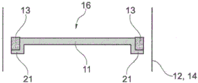
Fig. 2a and 2b schematically show known solutions for sealing and/or reinforcing openings or cavities in a motor vehicle. Fig. 2a shows the device 16 before the adhesive material 13 expands. Fig. 2b shows the same device 16 as an integral part of the system 1, however after expansion of the adhesive material 13, i.e. with the adhesive material 13' already expanded.
The device 16 is located in a cavity of the vehicle body structure, as it is shown for example in fig. 1. Fig. 2a and 2b schematically show a section of such a structural element 12, 14 of a vehicle body. The device 16 comprises a carrier 11 having an edge region 21. The adhesive material 13 is here arranged substantially on this edge region 21 of the carrier 11.
Before the adhesive material 13 expands, a gap exists between the device 16 and the structural elements 12, 14. This gap allows the structural elements 12, 14 to be coated for corrosion protection of the structural elements 12, 14. After this coating, the adhesive material 13 is usually expanded by the action of heat, wherein the expanded adhesive material 13' thus closes the gap between the device 16 and the structural elements 12, 14. Furthermore, the expansion of the adhesive material 13 simultaneously also achieves the fixing of the device 16' in the structural elements 12, 14. An apparatus 16' thus fastened in the structural elements 12, 14 reinforces the structural elements 12, 14 on the one hand and closes off the cavities in the structural elements 12, 14 on the other hand.
The disadvantages of the seals and/or reinforcements known to date are: these components are relatively complex, cumbersome to manufacture and costly.
Furthermore, the known seals and/or reinforcements have the disadvantage that: they have only limited preservability. This is especially because the adhesive material cannot be stored on the component for any long period of time and cannot be stored under extreme conditions.
Disclosure of Invention
It is therefore an object of the present invention to provide an improved system for insulating structural elements in a motor vehicle, which avoids the disadvantages of the prior art. The system should in particular bring economic advantages and in addition simplify or improve the relevant logistics and in particular the preservability.
This object is achieved by a system for insulating a structural element in a motor vehicle, comprising: a structural element having a first member and a second member, the members being joined together at a first joint and at a second joint, and the structural element defining a cavity; an apparatus having a carrier, wherein the carrier is arranged on the structural element by means of a fastening element; and an expandable adhesive material disposed on the structural element by pumping or by extrusion or on the carrier; wherein the carrier and the expandable adhesive material are constructed and arranged such that the carrier restricts expansion of the expandable adhesive material in at least one direction upon expansion thereof.
This solution has the advantage firstly that: the device can be made much simpler and more economical than in the prior art. In particular, the system according to the disclosure can use a device that is integrated and/or is composed of only one material and/or is produced in one operation. Thus, for example, a one-component injection molding method can be used instead of a two-component injection molding method. This reduces both the effective cost of manufacture and the expense of planning and configuring the equipment.
The core concept of the invention is as follows: the expandable adhesive material is not provided on the carrier before the device is fastened in the structural element, but the device is fastened in the structural element without adhesive material and the expandable adhesive material is introduced separately into the system. This has the advantage that: devices without adhesive material can be transported and stored better. This significantly reduces the associated logistic costs. The expandable adhesive material can be applied to the system in a correspondingly fresh manner on the production line of the motor vehicle, for example in the form of a bulk product.
An additional advantage of the system presented herein is that: by applying the expandable adhesive material alone, the inaccessible location of the cavity of the structural element can be reinforced, sealed, noise-free or insulated better than with the system described at the outset. In particular the expandable adhesive material is able to fill the joint completely already before it is activated.
Furthermore, the solution proposed here has the advantage that: the different structural elements can be insulated by means of a (standardized) device in such a way that different amounts and/or configurations of expandable adhesive material are used, respectively. Thus, for example, a first structural element having a larger cavity may be insulated using standard equipment and a larger amount of expandable adhesive material, while a second structural element having a smaller cavity may be insulated using the same standard equipment and a smaller amount of expandable adhesive material.
It is therefore necessary to make less number of different devices, so that the overall cost of the system can be reduced by a larger production volume, fewer tools and simpler logistics.
The expression "insulating" or "insulated" in connection with the present invention includes an element or a function or a structure or a method step for isolating and/or closing and/or reinforcing and/or eliminating noise and/or insulation of a structural element. These various properties of such insulation may be present here either alone or in combination with one another.
The structural element comprises at least a first component and a second component which are joined together at a first joint and at a second joint and thus form a cavity. The first and second components of the structural element can each be formed from one element or from a plurality of elements. The structural element may thus also have more than two joints.
In one exemplary embodiment, the system includes a plurality of devices having a carrier and a fastening element. For example, the system includes two devices, three devices, four devices, five devices, two or more devices, three or more devices, four or more devices, or five or more devices.
In this case, not only the contours of the plurality of devices, but also the materials thereof can be identical or different, respectively.
In one exemplary embodiment, the carrier is disposed on a first member of the structural element and the expandable adhesive material is disposed on a second member of the structural element.
In an alternative embodiment, the carrier is arranged on the first component of the structural element and the expandable adhesive material is likewise arranged on the first component of the structural element.
In an alternative development, the carrier is arranged on the first component of the structural element and the expandable adhesive material is arranged on the first component and on the second component of the structural element.
In a further alternative embodiment, the carrier is provided on the first member of the structural element and the expandable adhesive material is provided on the carrier.
In an exemplary embodiment, the carrier has a substantially L-shaped or I-shaped or H-shaped or C-shaped or T-shaped or W-shaped or V-shaped or U-shaped or N-shaped or Z-shaped or O-shaped or rectangular or oval or round or trapezoidal or triangular or polygonal cross section.
In one exemplary embodiment, the carrier has a base and a wing.
In one exemplary development, the fastening element is disposed on the base and the wings limit expansion of the expandable adhesive material in at least one direction.
In an exemplary development, the wing and the base are clamped at an angle of between 60 ° and 160 °, or between 70 ° and 150 °, or between 80 ° and 140 °.
In an exemplary embodiment, the device or only the carrier is produced by injection molding.
In an exemplary development, the device or only the carrier is produced by means of a one-component injection molding process.
In an alternative embodiment, the device or just the carrier is made by extrusion.
In an exemplary embodiment, the carrier and the fastening element are constructed in one piece.
In a further exemplary embodiment, the carrier and the fastening element are composed of the same material.
In an exemplary embodiment, the carrier comprises a plastic, in particular a polyamide.
In an exemplary embodiment, the carrier comprises a fiber-reinforced plastic, in particular a glass fiber-reinforced or carbon fiber-reinforced plastic.
The carrier can in principle be composed of different materials. Preferred materials are: plastics, in particular polyurethanes, polyamides, polyesters and polyolefins, preferably high-temperature-resistant polymers such as polyphenylene oxides, polysulfones or polyether sulfones, which are also foamed in particular; metals, particularly aluminum and steel; or a growing organic material, in particular wood or other (pressed) fibrous material or vitreous or ceramic material; in particular also foamed such materials; or any combination of these materials. Particular preference is given to using polyamides, in particular polyamide 6, polyamide 6.6, polyamide 11, polyamide 12 or mixtures thereof. Combinations with fibers such as glass fibers or carbon fibers may also be used.
Further, the carrier may have any configuration and any structure. It may be, for example, solid, hollow or foamed or have a lattice-like structure. The surface of the support may typically be smooth, rough or textured.
In an exemplary embodiment, the device has a substantially circular or elliptical or elongated or irregularly shaped profile.
In an exemplary embodiment, the expandable adhesive material has an expansion ratio of at least 200% or at least 300% or at least 400% or at least 500% or at least 800%.
One such expandable and pumpable adhesive material is described, for example, in european patent application EP 3 281 970 A1.
An example of such a pumpable expandable adhesive material is under the trade name Commercially available adhesive materials.
Examples of extrudable expandable adhesive materials are under the trade name 455 are available.
In an exemplary embodiment, the expandable adhesive material is arranged on the second component of the structural element in the shape of a bead or beads.
In one exemplary embodiment, the expandable adhesive material is disposed on the second member of the structural element by a robot.
In an exemplary embodiment, the at least one weld bead has a diameter of 2 to 20mm or 4 to 18mm or 6 to 16 mm.
In an exemplary embodiment, the at least one weld bead has a length of at least 10mm or at least 20mm or at least 30mm or at least 50mm or at least 100 mm.
In one exemplary embodiment, the expandable adhesive material is in contact with the structural element at the first joint and at the second joint.
In an exemplary embodiment, the expandable adhesive material is in contact with both the first and the second component of the structural element in the region of the first and the second joint, respectively.
In an exemplary embodiment, the expandable adhesive material has an extension of at least 10mm or at least 15mm or at least 20mm or at least 30mm or at least 40mm along the second member of the structural element starting from the joint, respectively.
In one exemplary embodiment, the expandable adhesive material constitutes a continuous element between the first joint and the second joint.
In one exemplary embodiment, the expandable adhesive material constitutes a single continuous element. In an alternative embodiment, the plurality of non-continuous expandable adhesive materials comprise a plurality of non-continuous elements.
In one exemplary embodiment, the expandable adhesive material is a pumpable or extrudable material.
In an exemplary embodiment, the expandable adhesive material is capable of being pumped at a temperature below 80 ℃, preferably below 70 ℃, preferably below 60 ℃, particularly preferably below 50 ℃.
In an exemplary embodiment, the expandable adhesive material can be extruded at a temperature below 100 ℃, preferably below 90 ℃, preferably below 80 ℃, particularly preferably below 70 ℃.
In an exemplary embodiment, the expandable adhesive material is capable of being pumped or extruded at a temperature at least 20K or at least 30K or at least 40K or at least 50K or at least 60K below the activation temperature of the second expandable adhesive material.
In an exemplary embodiment, the fastening element is configured as a clip.
In an alternative embodiment, the fastening element is configured as a welded plate or a magnetic element or an adhesive material or a hook.
In an exemplary embodiment, the structural element has an opening, wherein the carrier is arranged such that the opening is free of expanded adhesive material after expansion of the expandable adhesive material.
Such an arrangement of the carrier has the advantage that: in this way, the openings in the structural element, such as for example for a cable sleeve or the like, can be freed from the expanded adhesive material, so that such openings are not affected in their function.
In an exemplary embodiment, the distance between the carrier and the structural element is between 2 and 6mm or between 3 and 5 mm.
The object indicated at the outset is furthermore achieved by a method for insulating a structural element in a motor vehicle, comprising the following steps: providing a device having a carrier; disposing the device on the structural element; disposing the expandable adhesive material on the structural element or on the carrier by pumping or by extrusion; joining a first member and a second member of the structural element to form the structural element, wherein the device and the expandable adhesive material are disposed in a cavity between the members of the structural element; and expanding the expandable adhesive material, wherein the carrier restricts the expandable adhesive material from expanding in at least one direction.
In an exemplary embodiment, the expandable adhesive material is provided by pumping using a temperature of less than 80 ℃ or less than 70 ℃ or less than 60 ℃ or less than 50 ℃.
In an exemplary embodiment, the expandable adhesive material is provided by extrusion using a temperature of less than 100 ℃, or less than 90 ℃, or less than 80 ℃, or less than 70 ℃.
In an exemplary embodiment, the expandable adhesive material is expanded using a temperature above 100 ℃ or above 110 ℃ or above 120 ℃ or above 140 ℃.
In an exemplary embodiment, the method is implemented using the system described in the foregoing description.
In an exemplary embodiment, the expandable adhesive material is provided on the structural element or carrier by a robot.
In one exemplary embodiment, the expandable adhesive material is pumped or extruded onto the second member of the structural element.
In an exemplary embodiment, the adhesive material is provided on the structural element or the carrier before or after the device is provided on the first member of the structural element.
In an exemplary embodiment, heat is used in activating the expandable adhesive material, in particular in a paint oven or in a corrosion protection oven.
Drawings
The details and advantages of the invention will be described below by means of examples and with reference to the schematic drawings. In the accompanying drawings:
FIG. 1 is an exemplary diagram of a prior art vehicle body;
FIGS. 2a and 2b are schematic diagrams of exemplary devices of the prior art;
FIG. 3 is a schematic illustration of an exemplary device in one structural element;
FIGS. 4a and 4b are schematic diagrams of exemplary devices; and
fig. 5a to 6b are schematic diagrams of exemplary systems for insulating structural elements.
Detailed Description
A cross-sectional view of a device 16 in a structural element 12, 14 is schematically and exemplarily shown in fig. 3. In this embodiment, the device 16 has a carrier 11 which is L-shaped in cross section. Here, the first side constitutes a base 17 of the carrier and the second side constitutes a wing 18. The base 17 and the wing 18 are arranged at an angle 9, which in this embodiment is about 90. A fastening element 5 is provided on the base 17. The device 16 is arranged on the structural elements 12, 14 by means of this fastening element 5. In this embodiment, the fastening element 5 is configured as a clip.
The distance 4 between the carrier 11 and the structural elements 12, 14 is in this embodiment about 4mm. One such distance 4 allows on the one hand to coat the structural elements 12, 14 with a painting fluid before the expandable adhesive material expands, and on the other hand allows the carrier 11 to effectively limit the expansion of the expandable adhesive material in at least one direction.
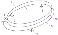
In fig. 4a and 4b, perspective views of two different devices 16 are schematically and exemplarily shown. The device 16 in fig. 4a has a substantially circular profile. Furthermore, the carrier 11 in this embodiment also has a substantially L-shaped cross section. The carrier 11 has a base 17 and a wing 18, which form an angle 9. In this embodiment, three fastening elements 5 for arranging the device 16 on one structural element are provided on the base 17.
The device 16 in fig. 4b has a rectangular cross section. The device 16 is configured elongate or has an elongate contour. The carrier 11 of the device 16 also has a base 17 and a wing 18 which form an angle 9 with each other. In this embodiment, the base 17 and the wings 18 are supplemented by further walls of the carrier 11. In this embodiment, two fastening elements 5 for arranging the device 16 on one structural element are provided on the base 17 of the carrier 11.
Fig. 5a to 6b schematically and exemplarily show a system 1 for insulating a structural element 12, 14.
Fig. 5a and 5b show a system 1 in which an expandable adhesive material 13 is arranged on the structural elements 12, 14. In this embodiment, the expandable adhesive material 13 is arranged on the first member 12.1, 14.1 of the structural element, while the device 16 is arranged on the second member 12.2, 14.2 of the structural element. The two components 12.1, 14.1, 12.2, 14.2 of the structural element are joined together at a first joint 6 and at a second joint 7. At the same time, the structural elements 12, 14 form a cavity 3 in which both the expandable adhesive material 13 and the device 16 are arranged.
The device 16 comprises a carrier 11 and a fastening element 5. The carrier 11 has a base 17 and a wing 18 which form an angle 9 with each other. The wing 18 is arranged in front of one opening 8 in the structural element 12, 14. In this way, the carrier 11 and in particular the wings 18 thereof limit the expansion of the expandable adhesive material 13 in the direction of this opening 8, so that the expanded adhesive material 13' cannot reach into the region of the opening 8. This can be seen in fig. 5b, which shows the system 1' after expansion of the expandable adhesive material 13.
Another exemplary system 1 for insulating structural elements 12, 14 is shown in fig. 6a and 6 b. Unlike the system 1 in fig. 5a and 5b, in this embodiment the expandable adhesive material 13 is not provided on the structural elements 12, 14, but on the carrier 11. The expandable adhesive material 13 is here arranged on the carrier 11 in the shape of a bead and by pumping or extrusion.
The carrier 11 also limits the expansion of the expandable adhesive material 13 in at least one direction, so that a predetermined region of the structural elements 12, 14 or of the cavities 3 thereof remains free of expanded adhesive material 13' after expansion of the expandable adhesive material 13. This is shown in fig. 6 b.
List of reference numerals
1. System and method for controlling a system
3. Cavity cavity
4. Spacing of
5. Fastening element
6. First joint part
7. Second joint
8. An opening
9. Included angle
10. Vehicle body
11. Carrier body
12. Structural element
12.1 First component
12.2 Second component
13. Expandable adhesive material
14. Structural element
14.1 First component
14.2 Second component
16. Apparatus and method for controlling the operation of a device
17. Base part
18. Wing part
21. Edge region
Claims (15)
1. A system (1) for insulating a structural element (12, 14) in a motor vehicle, the system (1) comprising:
-a structural element (12, 14) having a first member (12.1, 14.1) and a second member (12.2, 14.2), the first member (12.1, 14.1) and the second member (12.2, 14.2) being joined together at a first joint (6) and at a second joint (7), and the structural element (12, 14) constituting a cavity (3);
a device (16) having a carrier (11), the carrier (11) being arranged on the structural elements (12, 14) by means of the fastening element (5); and
an expandable adhesive material (13) which is arranged on the structural elements (12, 14) by pumping or by extrusion;
the carrier (11) and the expandable adhesive material (13) are constructed and arranged such that the carrier (11) restricts expansion of the expandable adhesive material (13) in at least one direction upon expansion thereof.
2. A system according to claim 1, characterized in that the carrier (11) is arranged on a first component (12.1, 14.1) of the structural element (12, 14) and the expandable adhesive material (13) is arranged on a second component (12.2, 14.2) of the structural element (12, 14).
3. A system according to claim 1 or 2, characterized in that the carrier (11) has a base (17) and wings (18), and that the fastening element is arranged on the base (17) and that the wings (18) limit the expansion of the expandable adhesive material (13) in at least one direction.
4. A system (1) according to claim 3, wherein the wing (18) and the base (17) form an angle of between 60 ° and 160 °.
5. The system according to claim 1 or 2, characterized in that the device (16) is manufactured by injection moulding and/or that the device (16) is composed of only one material and/or that the device (16) is constructed in one piece.
6. A system according to claim 1 or 2, characterized in that the device (16) has a substantially circular or oval or elongated or irregularly shaped profile.
7. A system according to claim 1 or 2, characterized in that the expandable adhesive material (13) has an expansion ratio of at least 200%.
8. A system according to claim 1 or 2, characterized in that the expandable adhesive material (13) is arranged on the structural element (12, 14) in the form of a bead or beads.
9. A system according to claim 1 or 2, characterized in that the expandable adhesive material (13) is constructed as one continuous element or as a plurality of discontinuous elements.
10. A system as claimed in claim 1 or 2, characterized in that the fastening element (5) is configured as a clip.
11. A system according to claim 1 or 2, characterized in that the structural element (12, 14) has an opening (8) and the carrier (11) is arranged such that the opening (8) is free of expanded adhesive material (13') after expansion of the expandable adhesive material (13).
12. A system (1) according to claim 1 or 2, characterized in that the spacing (4) between the carrier (11) and the structural element (12, 14) is between 2mm and 6 mm.
13. A method for insulating a structural element (12, 14) in a motor vehicle, the method comprising the steps of:
providing a device (16) with a carrier (11);
-providing a device (16) on the structural element (12, 14);
-providing an expandable adhesive material (13) on the structural elements (12, 14) by pumping or by extrusion;
joining a first component (12.1, 14.1) of the structural element (12, 14) to a second component (12.2, 14.2) to form the structural element (12, 14),
-the device (16) and the expandable adhesive material (13) are arranged in the cavity (3) between said first (12.1, 14.1) and second (12.2, 14.2) members of the structural element (12, 14); and is also provided with
The expandable adhesive material (13) is expanded and the carrier (11) restricts expansion of the expandable adhesive material (13) in at least one direction.
14. Method according to claim 13, characterized in that the expandable adhesive material (13) is provided by pumping or by extrusion with a temperature below 80 ℃ and/or the expandable adhesive material (13) is expanded with a temperature above 100 ℃.
15. The method according to claim 13 or 14, characterized in that the method is carried out with a system (1) according to any one of claims 1 to 12.
Applications Claiming Priority (3)
| Application Number | Priority Date | Filing Date | Title |
|---|---|---|---|
| EP18192073.7 | 2018-08-31 | ||
| EP18192073 | 2018-08-31 | ||
| PCT/EP2019/072884 WO2020043739A1 (en) | 2018-08-31 | 2019-08-27 | System for insulating a structural element |
Publications (2)
| Publication Number | Publication Date |
|---|---|
| CN112638752A CN112638752A (en) | 2021-04-09 |
| CN112638752B true CN112638752B (en) | 2023-05-05 |
Family
ID=63490234
Family Applications (1)
| Application Number | Title | Priority Date | Filing Date |
|---|---|---|---|
| CN201980056444.8A Active CN112638752B (en) | 2018-08-31 | 2019-08-27 | System for insulating a structural element |
Country Status (6)
| Country | Link |
|---|---|
| US (1) | US20210179191A1 (en) |
| EP (2) | EP4223618A3 (en) |
| KR (1) | KR102618225B1 (en) |
| CN (1) | CN112638752B (en) |
| ES (1) | ES2949792T3 (en) |
| WO (1) | WO2020043739A1 (en) |
Citations (13)
| Publication number | Priority date | Publication date | Assignee | Title |
|---|---|---|---|---|
| KR20020090666A (en) * | 2001-05-29 | 2002-12-05 | 지엠대우자동차기술 주식회사 | Noise preventing structure of pillar for automobiles |
| JP2004004445A (en) * | 2002-04-11 | 2004-01-08 | Kyowa Sangyo Kk | Hollow chamber shutoff implement of hollow structured object |
| CN1531489A (en) * | 2001-07-02 | 2004-09-22 | 哈特奇桑公司 | Sound insulating device designed to be mounted in tubular part, in particular motor vehicle body part |
| CN1646288A (en) * | 2002-04-15 | 2005-07-27 | 陶氏环球技术公司 | Improved vehicular structural members and method of making the members |
| WO2008065049A1 (en) * | 2006-11-27 | 2008-06-05 | Henkel Ag & Co. Kgaa | Expandable filler insert and methods of producing the expandable filler insert |
| JP2009083497A (en) * | 2008-11-07 | 2009-04-23 | Nitto Denko Corp | Foamed filling member |
| CN101678796A (en) * | 2007-03-28 | 2010-03-24 | 汉高两合股份公司 | Sound-absorbing baffle for sealing a hollow space |
| CN101802062A (en) * | 2007-09-19 | 2010-08-11 | 汉高两合股份公司 | Highly damping expandable material and devices |
| CN102177013A (en) * | 2008-07-29 | 2011-09-07 | 陶氏环球技术有限责任公司 | Toughened expandable epoxy resins for stiffening and energy dissipation in automotive cavities |
| DE102011000450A1 (en) * | 2011-02-02 | 2012-08-02 | Dr. Ing. H.C. F. Porsche Aktiengesellschaft | Support structure for producing e.g. A-pillar of vehicle, has expandable adhesive material between structural element and reinforcement element, which surrounds three sides of portion of reinforcement element facing auxiliary frame |
| CN102673653A (en) * | 2011-03-16 | 2012-09-19 | 通用汽车环球科技运作有限责任公司 | Reinforced structural assembly with acoustic foam member and method of reinforcing vehicle components |
| WO2014095620A1 (en) * | 2012-12-21 | 2014-06-26 | Sika Technology Ag | Insulation element, expanded insulation element, use of same and method for insulation |
| WO2017158143A1 (en) * | 2016-03-18 | 2017-09-21 | Sika Technology Ag | Insulating element |
Family Cites Families (8)
| Publication number | Priority date | Publication date | Assignee | Title |
|---|---|---|---|---|
| US5266133A (en) * | 1993-02-17 | 1993-11-30 | Sika Corporation | Dry expansible sealant and baffle composition and product |
| US6247287B1 (en) * | 1998-08-05 | 2001-06-19 | Neo-Ex Lab, Inc. | Structure and method for closing and reinforcing hollow structural members |
| US6387470B1 (en) * | 1998-11-05 | 2002-05-14 | Sika Corporation | Sound deadening and structural reinforcement compositions and methods of using the same |
| US7597382B2 (en) * | 2005-06-07 | 2009-10-06 | Zephyros, Inc. | Noise reduction member and system |
| CA2670642A1 (en) * | 2006-12-28 | 2008-07-10 | Henkel Ag & Co. Kgaa | Acoustic baffle |
| GB2463858A (en) * | 2008-08-20 | 2010-03-31 | Zephyros Inc | Foamed insulation |
| KR20110091876A (en) * | 2008-11-26 | 2011-08-16 | 다우 글로벌 테크놀로지스 엘엘씨 | Acoustic baffle members and methods for applying acoustic baffles in cavities |
| BR102017016857B1 (en) | 2016-08-08 | 2023-02-14 | Sika Technology Ag | FILLER COMPOSITION, FILLER AGENT, USE OF THE COMPOSITION, METHOD FOR FILLING AN CLOSED SPACE AND VEHICLE PART |
-
2019
- 2019-08-27 EP EP23166716.3A patent/EP4223618A3/en active Pending
- 2019-08-27 CN CN201980056444.8A patent/CN112638752B/en active Active
- 2019-08-27 ES ES19758417T patent/ES2949792T3/en active Active
- 2019-08-27 US US17/269,426 patent/US20210179191A1/en active Pending
- 2019-08-27 EP EP19758417.0A patent/EP3844051B1/en active Active
- 2019-08-27 KR KR1020217004568A patent/KR102618225B1/en active IP Right Grant
- 2019-08-27 WO PCT/EP2019/072884 patent/WO2020043739A1/en unknown
Patent Citations (13)
| Publication number | Priority date | Publication date | Assignee | Title |
|---|---|---|---|---|
| KR20020090666A (en) * | 2001-05-29 | 2002-12-05 | 지엠대우자동차기술 주식회사 | Noise preventing structure of pillar for automobiles |
| CN1531489A (en) * | 2001-07-02 | 2004-09-22 | 哈特奇桑公司 | Sound insulating device designed to be mounted in tubular part, in particular motor vehicle body part |
| JP2004004445A (en) * | 2002-04-11 | 2004-01-08 | Kyowa Sangyo Kk | Hollow chamber shutoff implement of hollow structured object |
| CN1646288A (en) * | 2002-04-15 | 2005-07-27 | 陶氏环球技术公司 | Improved vehicular structural members and method of making the members |
| WO2008065049A1 (en) * | 2006-11-27 | 2008-06-05 | Henkel Ag & Co. Kgaa | Expandable filler insert and methods of producing the expandable filler insert |
| CN101678796A (en) * | 2007-03-28 | 2010-03-24 | 汉高两合股份公司 | Sound-absorbing baffle for sealing a hollow space |
| CN101802062A (en) * | 2007-09-19 | 2010-08-11 | 汉高两合股份公司 | Highly damping expandable material and devices |
| CN102177013A (en) * | 2008-07-29 | 2011-09-07 | 陶氏环球技术有限责任公司 | Toughened expandable epoxy resins for stiffening and energy dissipation in automotive cavities |
| JP2009083497A (en) * | 2008-11-07 | 2009-04-23 | Nitto Denko Corp | Foamed filling member |
| DE102011000450A1 (en) * | 2011-02-02 | 2012-08-02 | Dr. Ing. H.C. F. Porsche Aktiengesellschaft | Support structure for producing e.g. A-pillar of vehicle, has expandable adhesive material between structural element and reinforcement element, which surrounds three sides of portion of reinforcement element facing auxiliary frame |
| CN102673653A (en) * | 2011-03-16 | 2012-09-19 | 通用汽车环球科技运作有限责任公司 | Reinforced structural assembly with acoustic foam member and method of reinforcing vehicle components |
| WO2014095620A1 (en) * | 2012-12-21 | 2014-06-26 | Sika Technology Ag | Insulation element, expanded insulation element, use of same and method for insulation |
| WO2017158143A1 (en) * | 2016-03-18 | 2017-09-21 | Sika Technology Ag | Insulating element |
Also Published As
| Publication number | Publication date |
|---|---|
| EP3844051A1 (en) | 2021-07-07 |
| KR20210053283A (en) | 2021-05-11 |
| EP4223618A2 (en) | 2023-08-09 |
| KR102618225B1 (en) | 2023-12-27 |
| CN112638752A (en) | 2021-04-09 |
| ES2949792T3 (en) | 2023-10-03 |
| WO2020043739A1 (en) | 2020-03-05 |
| EP4223618A3 (en) | 2023-08-23 |
| US20210179191A1 (en) | 2021-06-17 |
| EP3844051B1 (en) | 2023-06-07 |
Similar Documents
| Publication | Publication Date | Title |
|---|---|---|
| JP5903454B2 (en) | Sealed aluminum honeycomb structural reinforcement | |
| US9623814B2 (en) | Reinforcement with channel design | |
| US7479246B2 (en) | Overmoulding | |
| US20120043019A1 (en) | Bonding with adhesive beads or plots | |
| US10906595B2 (en) | Device for reinforcing a structural element | |
| EP2334540B1 (en) | Bonding with adhesive beads or plots | |
| US8746780B2 (en) | Structural reinforcer with bonding material on orthoganal surfaces | |
| CN102317140B (en) | Structural reinforcement system | |
| US10472001B2 (en) | Vehicle body frame including structural bulkhead with acoustic spray foam control | |
| JP2010242970A5 (en) | ||
| JP2010242970A (en) | Element which seals or reinforces cavity and method how to adopt penetration element into such element | |
| CN103379986A (en) | Sealing assembly | |
| CN112638752B (en) | System for insulating a structural element | |
| US11814110B2 (en) | System for insulating a structural element | |
| CN112638753B (en) | Device for reinforcing, sealing or damping a structural element | |
| US11332199B2 (en) | Device for reinforcing, sealing or damping a structural element | |
| WO2012062448A1 (en) | Improvements in or relating to plugs | |
| US20200353996A1 (en) | Device for reinforcing a structural element | |
| US10829164B2 (en) | Body member | |
| EP3891048A1 (en) | Reinforcement with integrated stop device |
Legal Events
| Date | Code | Title | Description |
|---|---|---|---|
| PB01 | Publication | ||
| PB01 | Publication | ||
| SE01 | Entry into force of request for substantive examination | ||
| SE01 | Entry into force of request for substantive examination | ||
| GR01 | Patent grant | ||
| GR01 | Patent grant |