EP2159023B1 - Machining centre for machining components made of wood or the like having an elongated shape, in particular components for frames - Google Patents
Machining centre for machining components made of wood or the like having an elongated shape, in particular components for frames Download PDFInfo
- Publication number
- EP2159023B1 EP2159023B1 EP09169191.5A EP09169191A EP2159023B1 EP 2159023 B1 EP2159023 B1 EP 2159023B1 EP 09169191 A EP09169191 A EP 09169191A EP 2159023 B1 EP2159023 B1 EP 2159023B1
- Authority
- EP
- European Patent Office
- Prior art keywords
- machining centre
- machining
- components
- component
- centre according
- Prior art date
- Legal status (The legal status is an assumption and is not a legal conclusion. Google has not performed a legal analysis and makes no representation as to the accuracy of the status listed.)
- Active
Links
- 238000003754 machining Methods 0.000 title claims description 38
- 239000002023 wood Substances 0.000 title claims description 7
- 238000005070 sampling Methods 0.000 claims description 10
- 238000005553 drilling Methods 0.000 claims description 4
- 230000008878 coupling Effects 0.000 claims description 3
- 238000010168 coupling process Methods 0.000 claims description 3
- 238000005859 coupling reaction Methods 0.000 claims description 3
- 238000002372 labelling Methods 0.000 claims description 2
- 238000003801 milling Methods 0.000 claims 1
- 239000003292 glue Substances 0.000 description 3
- 238000003780 insertion Methods 0.000 description 2
- 230000037431 insertion Effects 0.000 description 2
- 238000004026 adhesive bonding Methods 0.000 description 1
- 238000004140 cleaning Methods 0.000 description 1
- 230000007547 defect Effects 0.000 description 1
- 238000012423 maintenance Methods 0.000 description 1
- 238000004519 manufacturing process Methods 0.000 description 1
- 238000000034 method Methods 0.000 description 1
- 238000005086 pumping Methods 0.000 description 1
Images

Classifications
-
- B—PERFORMING OPERATIONS; TRANSPORTING
- B23—MACHINE TOOLS; METAL-WORKING NOT OTHERWISE PROVIDED FOR
- B23Q—DETAILS, COMPONENTS, OR ACCESSORIES FOR MACHINE TOOLS, e.g. ARRANGEMENTS FOR COPYING OR CONTROLLING; MACHINE TOOLS IN GENERAL CHARACTERISED BY THE CONSTRUCTION OF PARTICULAR DETAILS OR COMPONENTS; COMBINATIONS OR ASSOCIATIONS OF METAL-WORKING MACHINES, NOT DIRECTED TO A PARTICULAR RESULT
- B23Q7/00—Arrangements for handling work specially combined with or arranged in, or specially adapted for use in connection with, machine tools, e.g. for conveying, loading, positioning, discharging, sorting
- B23Q7/04—Arrangements for handling work specially combined with or arranged in, or specially adapted for use in connection with, machine tools, e.g. for conveying, loading, positioning, discharging, sorting by means of grippers
-
- B—PERFORMING OPERATIONS; TRANSPORTING
- B23—MACHINE TOOLS; METAL-WORKING NOT OTHERWISE PROVIDED FOR
- B23Q—DETAILS, COMPONENTS, OR ACCESSORIES FOR MACHINE TOOLS, e.g. ARRANGEMENTS FOR COPYING OR CONTROLLING; MACHINE TOOLS IN GENERAL CHARACTERISED BY THE CONSTRUCTION OF PARTICULAR DETAILS OR COMPONENTS; COMBINATIONS OR ASSOCIATIONS OF METAL-WORKING MACHINES, NOT DIRECTED TO A PARTICULAR RESULT
- B23Q7/00—Arrangements for handling work specially combined with or arranged in, or specially adapted for use in connection with, machine tools, e.g. for conveying, loading, positioning, discharging, sorting
- B23Q7/001—Lateral transport of long workpieces
-
- B—PERFORMING OPERATIONS; TRANSPORTING
- B27—WORKING OR PRESERVING WOOD OR SIMILAR MATERIAL; NAILING OR STAPLING MACHINES IN GENERAL
- B27M—WORKING OF WOOD NOT PROVIDED FOR IN SUBCLASSES B27B - B27L; MANUFACTURE OF SPECIFIC WOODEN ARTICLES
- B27M1/00—Working of wood not provided for in subclasses B27B - B27L, e.g. by stretching
- B27M1/08—Working of wood not provided for in subclasses B27B - B27L, e.g. by stretching by multi-step processes
Definitions
- the present invention relates to a machining centre for machining components made of wood or the like having an elongated shape, in particular components for frames.
- a prior art machining centre comprises a forming machine in turn comprising a first gripping device, which extends in a first given direction, and is provided with a plurality of clamping vices for locking at least one component parallel to said first direction, a second gripping device, which faces the first gripping device, extends in the first direction, and is provided with a plurality of clamping vices for locking at least one component parallel to said first direction, and two working heads mobile in the first direction for longitudinally profiling the components locked in the first and second gripping device.
- the two gripping devices are also mobile with respect to one another in a second direction transversal to the first direction to allow each component to be transferred from the first to the second gripping device.
- the machining centre also comprises a unit for removing the components from the second gripping device.
- the sampling unit normally comprises a conveyor belt, which extends in the first direction, and cooperates with a pushing member mobile inside the clamping vices in said first direction so as to release the newly-machined component from the clamping vices and move it onto the conveyor belt.
- Document EP-1992464-A discloses a machining centre for machining elongated-shaped components made of wood or the like comprising an overhead travelling crane provided with a vertical upright and with a horizontal cross member, which is fixed to the free end of the upright, and extends in a first direction; a first gripping device provided with at least a first clamping vice for locking at least a component parallel to a horizontal second direction transversal to the first direction; a second gripping device facing the first gripping device and provided with at least a second clamping vice for locking at least a component parallel to the second direction; and a working head mounted on the cross member.
- the cross member is mobile in the second direction to allow the working head to longitudinally profiling the components locked in the first and/or second gripping device.
- the machining centre further comprises a sampling unit mounted on the cross member for extracting the components from the first and/or second gripping device.
- a machining centre for machining components made of wood or the like having an elongated shape, in particular components for frames, as claimed in claim 1.
- machining centre 1 for machining components 2 made of wood for frames having an elongated shape.
- the machining centre 1 comprises a forming machine 3 in turn comprising a gantry frame 4 with two upright members 5 parallel to one another and to a substantially vertical direction 6 and a cross member 7, which is fixed to the free ends of the upright members 5, extends in a substantially horizontal direction 8 transversal to the direction 6, and is limited laterally in a horizontal direction 9 orthogonal to the directions 6 and 8 by two substantially flat faces 7a, 7b, on each of which is mounted a relative working head 10.
- the head 10 is connected in a conventional manner to the cross member 7 so as to perform, along the cross member 7 and driven by a conventional drive device that is not illustrated, rectilinear movements in the direction 8, and is provided with at least one electric spindle and a drilling unit (known and not illustrated) which are mounted in a conventional manner on the head 10 so as to perform, with respect to the head 10 and driven by a conventional drive device that is not illustrated, rectilinear movements in the direction 6.
- the working heads 10 can be moved in the direction 8 either independently of one another, or synchronously with one another.
- the forming machine 3 also comprises two longitudinal guiding members 11, which extend in the direction 9, are mounted inside the upright members 5, and support two gripping and transfer devices 12, 13 that face one another.
- Each device 12, 13 comprises a supporting bar 14, which is slidingly coupled to the longitudinal members 11 so as to perform, along the longitudinal members 11 and driven by a conventional drive device that is not illustrated, rectilinear movements in the direction 9, and is upperly limited by a substantially flat and horizontal surface to which a plurality of lower jaws 15 of relative clamping vices 16 are attached, which face the vices 16 of the other device 12, 13 and also comprise respective upper jaws 17 that are substantially L-shaped.
- the jaws 17 of each device 12, 13 are divided into a plurality of mutually independent sets of jaws 17 (in the specific case two sets of jaws 17), and the jaws 17 of each set of jaws 17 protrude upwards from a relative slide 18 connected in a conventional manner to the bar 14 so as to perform, with respect to the bar 14 and driven by a plurality of actuating cylinders 19 (in the specific case three actuating cylinders 19) connected to the bar 14, rectilinear movements in the direction 6 and move the relative jaws 17 between a locked position and a released position of at least one component 2.
- each component 2 is loaded, by hand or automatically, onto the gripping and transfer device 12 and is longitudinally profiled along a face 2a thereof protruding outwards from the vices 16 of the device 12 by the working head 10 mounted on the side 7a of the cross member 7.
- the component 2 is transferred from the vices 16 of the device 12 to the vices 16 of the device 13, and is then longitudinally profiled along a face 2b thereof opposite the face 2a and protruding outwards from the vices 16 of the device 13 by the working head 10 mounted on the side 7b of the cross member 7.
- the components 2 are removed from the device 13 by means of a sampling unit 20, which is aligned with the forming machine 3 in the direction 9, and is provided with a supporting frame 21 comprising two pairs of vertical rods 22 parallel to one another and to the direction 6.
- Each pair of vertical rods 22 supports a longitudinal guiding member 23 connected to the free ends of the relative vertical rods 22 parallel to the direction 9.
- the unit 20 also comprises a cross element 24, which extends between the longitudinal members 23 in the direction 8, is connected in a conventional manner to the longitudinal members 23 so as to perform, along the longitudinal members 23 and driven by a conventional drive device that is not illustrated, rectilinear movements in the direction 9, and supports a grip and transfer device D comprising a plurality of gripping and transferring members 25, in the specific case two gripping and transferring members 25, mounted on a side of the cross element 24.
- Each member 25 comprises a slide 26, which is connected in a conventional manner to the cross element 24 so as to perform, along the cross element 24 and driven by a conventional drive device that is not illustrated, rectilinear movements in the direction 8, and supports a clamping vice 27 comprising a lower jaw 28 connected in a conventional manner to the slide 26 so as to perform, with respect to said slide 26, rectilinear movements in the direction 6 and an upper jaw 29 connected in a conventional manner to the jaw 28 so as to perform, with respect to said jaw 28, rectilinear movements in the direction 6 between a locked position and a released position of at least one component 2.
- the machining centre 1 also comprises, in the specific case, two conventional inserting units 30 arranged on opposite sides of the frame 21 in the direction 8 for inserting coupling pins (not illustrated) inside relative holes 31 made by the heads 10 in the head ends of the components 2 parallel to the direction 8.
- Each unit 30 comprises a gumming nozzle 32, which is connected to a glue containing tank 33 by means of a pumping device 34, and is suitable to deliver glue inside the relative holes 31, and an insertion device 35, which is connected to a hopper 36 that contains pins, and is suitable to insert a pin (not illustrated) inside each relative hole 31.
- the machining centre 1 comprises a conveyor device 37, which extends in the direction 8, and in turn comprises a roller conveyor 38 suitable to receive the components 2 from the sampling unit 20 and a conveyor belt 39 arranged in series with the conveyor 38.
- the jaws 28, 29 of the vices 27 present a width, measured parallel to the direction 8, that is approximating by defect the distance between the jaws 15, 17 of two adjacent vices 16, and also the distance between two adjacent rollers of the conveyor 38.
- the jaws 28, 29 of the vices 27 are engaged between the jaws 15, 17 of the vices 16 of the device 13 enabling the unit 20 to remove the component 2 from the forming machine 3, feed it in sequence to the two units 30, and unload it onto the conveyor 38.
Description
- The present invention relates to a machining centre for machining components made of wood or the like having an elongated shape, in particular components for frames.
- In the field of manufacturing components for frames, a prior art machining centre comprises a forming machine in turn comprising a first gripping device, which extends in a first given direction, and is provided with a plurality of clamping vices for locking at least one component parallel to said first direction, a second gripping device, which faces the first gripping device, extends in the first direction, and is provided with a plurality of clamping vices for locking at least one component parallel to said first direction, and two working heads mobile in the first direction for longitudinally profiling the components locked in the first and second gripping device.
- The two gripping devices are also mobile with respect to one another in a second direction transversal to the first direction to allow each component to be transferred from the first to the second gripping device.
- The machining centre also comprises a unit for removing the components from the second gripping device. The sampling unit normally comprises a conveyor belt, which extends in the first direction, and cooperates with a pushing member mobile inside the clamping vices in said first direction so as to release the newly-machined component from the clamping vices and move it onto the conveyor belt.
- The prior art machining centres of the type described above have some drawbacks mainly deriving from the fact that the conveyor belt of the sampling unit is unable to guarantee correct positioning of the components, especially in case of shaped components, and thus prevents performance of precision machining processes after profiling.
- In particular, when the processes to be performed after profiling involve the gluing of additional elements such as, for instance, coupling pins onto the components, the glue applied to the components could drip onto the conveyor belt and thus result in the need for frequent servicing and cleaning of said conveyor belt by machine maintenance personnel.
- Document
EP-1992464-A discloses a machining centre for machining elongated-shaped components made of wood or the like comprising an overhead travelling crane provided with a vertical upright and with a horizontal cross member, which is fixed to the free end of the upright, and extends in a first direction; a first gripping device provided with at least a first clamping vice for locking at least a component parallel to a horizontal second direction transversal to the first direction; a second gripping device facing the first gripping device and provided with at least a second clamping vice for locking at least a component parallel to the second direction; and a working head mounted on the cross member. - The cross member is mobile in the second direction to allow the working head to longitudinally profiling the components locked in the first and/or second gripping device.
- The machining centre further comprises a sampling unit mounted on the cross member for extracting the components from the first and/or second gripping device.
- It is an object of the present invention to provide a machining centre for machining components made of wood or the like having an elongated shape, in particular components for frames, that overcomes the drawbacks described above and is simple and economical to produce.
- According to the present invention there is provided a machining centre for machining components made of wood or the like having an elongated shape, in particular components for frames, as claimed in claim 1.
- The present invention will now be described with reference to the accompanying drawings, illustrating a non-limiting embodiment thereof, in which:
-
figure 1 is a schematic perspective view of a preferred embodiment of the machining centre according to the present invention; and -
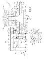
figure 2 is a schematic side view, with parts enlarged for the sake of clarity, of the machining centre offigure 1 . - With reference to
figure 1 , designated as a whole by number 1 is a machining centre formachining components 2 made of wood for frames having an elongated shape. - The machining centre 1 comprises a forming
machine 3 in turn comprising a gantry frame 4 with twoupright members 5 parallel to one another and to a substantiallyvertical direction 6 and across member 7, which is fixed to the free ends of theupright members 5, extends in a substantiallyhorizontal direction 8 transversal to thedirection 6, and is limited laterally in ahorizontal direction 9 orthogonal to thedirections flat faces head 10. - The
head 10 is connected in a conventional manner to thecross member 7 so as to perform, along thecross member 7 and driven by a conventional drive device that is not illustrated, rectilinear movements in thedirection 8, and is provided with at least one electric spindle and a drilling unit (known and not illustrated) which are mounted in a conventional manner on thehead 10 so as to perform, with respect to thehead 10 and driven by a conventional drive device that is not illustrated, rectilinear movements in thedirection 6. - With regard to the above description it should be noted that the
working heads 10 can be moved in thedirection 8 either independently of one another, or synchronously with one another. - The forming
machine 3 also comprises two longitudinal guiding members 11, which extend in thedirection 9, are mounted inside theupright members 5, and support two gripping andtransfer devices - Each
device bar 14, which is slidingly coupled to the longitudinal members 11 so as to perform, along the longitudinal members 11 and driven by a conventional drive device that is not illustrated, rectilinear movements in thedirection 9, and is upperly limited by a substantially flat and horizontal surface to which a plurality oflower jaws 15 ofrelative clamping vices 16 are attached, which face thevices 16 of theother device upper jaws 17 that are substantially L-shaped. - The
jaws 17 of eachdevice jaws 17 of each set ofjaws 17 protrude upwards from arelative slide 18 connected in a conventional manner to thebar 14 so as to perform, with respect to thebar 14 and driven by a plurality of actuating cylinders 19 (in the specific case three actuating cylinders 19) connected to thebar 14, rectilinear movements in thedirection 6 and move therelative jaws 17 between a locked position and a released position of at least onecomponent 2. - In use, each
component 2 is loaded, by hand or automatically, onto the gripping andtransfer device 12 and is longitudinally profiled along aface 2a thereof protruding outwards from thevices 16 of thedevice 12 by theworking head 10 mounted on theside 7a of thecross member 7. - When the
face 2a has been profiled, thecomponent 2 is transferred from thevices 16 of thedevice 12 to thevices 16 of thedevice 13, and is then longitudinally profiled along aface 2b thereof opposite theface 2a and protruding outwards from thevices 16 of thedevice 13 by the workinghead 10 mounted on theside 7b of thecross member 7. - When the
faces component 2 in thedirection 8, thecomponents 2 are removed from thedevice 13 by means of asampling unit 20, which is aligned with the formingmachine 3 in thedirection 9, and is provided with a supportingframe 21 comprising two pairs ofvertical rods 22 parallel to one another and to thedirection 6. Each pair ofvertical rods 22 supports a longitudinal guidingmember 23 connected to the free ends of the relativevertical rods 22 parallel to thedirection 9. - The
unit 20 also comprises across element 24, which extends between thelongitudinal members 23 in thedirection 8, is connected in a conventional manner to thelongitudinal members 23 so as to perform, along thelongitudinal members 23 and driven by a conventional drive device that is not illustrated, rectilinear movements in thedirection 9, and supports a grip and transfer device D comprising a plurality of gripping and transferringmembers 25, in the specific case two gripping and transferringmembers 25, mounted on a side of thecross element 24. - Each
member 25 comprises aslide 26, which is connected in a conventional manner to thecross element 24 so as to perform, along thecross element 24 and driven by a conventional drive device that is not illustrated, rectilinear movements in thedirection 8, and supports aclamping vice 27 comprising alower jaw 28 connected in a conventional manner to theslide 26 so as to perform, with respect to saidslide 26, rectilinear movements in thedirection 6 and anupper jaw 29 connected in a conventional manner to thejaw 28 so as to perform, with respect to saidjaw 28, rectilinear movements in thedirection 6 between a locked position and a released position of at least onecomponent 2. - The machining centre 1 also comprises, in the specific case, two conventional
inserting units 30 arranged on opposite sides of theframe 21 in thedirection 8 for inserting coupling pins (not illustrated) insiderelative holes 31 made by theheads 10 in the head ends of thecomponents 2 parallel to thedirection 8. - Each
unit 30 comprises agumming nozzle 32, which is connected to aglue containing tank 33 by means of apumping device 34, and is suitable to deliver glue inside therelative holes 31, and aninsertion device 35, which is connected to ahopper 36 that contains pins, and is suitable to insert a pin (not illustrated) inside eachrelative hole 31. - Lastly, the machining centre 1 comprises a
conveyor device 37, which extends in thedirection 8, and in turn comprises aroller conveyor 38 suitable to receive thecomponents 2 from thesampling unit 20 and aconveyor belt 39 arranged in series with theconveyor 38. - As regards the above description it should be noted that the
jaws vices 27 present a width, measured parallel to thedirection 8, that is approximating by defect the distance between thejaws adjacent vices 16, and also the distance between two adjacent rollers of theconveyor 38. - Thus, in use, combining the movements of the
cross element 24 in thedirection 9 with the movements of theslides 26 in thedirection 8 and with the movements of thevices 27 in thedirection 6, thejaws vices 27 are engaged between thejaws vices 16 of thedevice 13 enabling theunit 20 to remove thecomponent 2 from the formingmachine 3, feed it in sequence to the twounits 30, and unload it onto theconveyor 38. - From the above description it is clear that from when it is inserted into the
device 12 until being released onto theconveyor 38, thecomponent 2 is always kept inside thevices 16 and/or 27 and at a given distance from the floor, thus preventing the need for any intermediate repositioning of saidcomponent 2. - According to some alternative embodiments that are not illustrated:
- the
unit 20 is provided with two grip and transfer devices D mounted on the same side or on opposite sides of thecross element 24; - the
units 30 are eliminated and theunit 20 transfers thecomponents 2 directly from thedevice 13 onto theconveyor 38; - the
unit 20 cooperates with at least one device for marking and/or labelling thecomponents 2, for example using RFID tags; - the
unit 20 cooperates with other insertion units, used in addition to or instead of theunits 30, suitable to insert the ironmongery elements for frames, for example handles, hinges, pintles, inside relative seats made by theheads 10 in thecomponents 2; and - the
cross member 7 is mobile in thedirection 9 and thedevices direction 9.
Claims (11)
- Machining centre for machining elongated-shaped components (2) made of wood or the like, in particular components (2) for frames, the machining centre comprising a forming machine (3) and at least a sampling unit (20) of the components (2) from the forming machine (3); the forming machine (3) comprising, in turn, a gantry frame (4) provided with two upright members (5) parallel to one another and to a substantially vertical first direction (6) and with a cross member (7), which is fixed to the free ends of the upright members (5), and extends in a substantially horizontal second direction (8) transversal to the first direction 6); a first gripping device (12) provided with at least a first clamping vice (16) for locking at least a component (2) parallelly to the second direction (8), a second gripping device (13) facing the first gripping device (12) and provided with at least a second clamping vice (16) for locking at least a component (2) parallelly to the second direction (8), and at least a working head (10) mobile along the cross member (7) in the second direction (8) for longitudinally profiling the components (2) locked in the first and/or second gripping device (12, 13); the sampling unit (20) comprising at least a grip and transfer device (D) provided with at least a third clamping vice (27) mobile in a third direction (9) substantially orthogonal to said first and second directions (6, 8) for extracting at least a component (2) from the first and/or second gripping device (12, 13).
- Machining centre according to claim 1, wherein the third clamping vice (27) is further mobile in the first direction (6) and/or in the second direction (8).
- Machining centre according to claim 1 or 2, wherein the sampling unit (20) comprises a cross element (24), which extends in the second direction (8) and is mobile in the third direction (9); the grip and transfer device (D) being supported by the cross element (24).
- Machining centre according to claim 3 and further comprising at least two grip and transfer devices (D) mounted on the opposite sides of said cross element (24).
- Machining centre according to one of the preceding claims, wherein each said first and second gripping device (12, 13) comprises a plurality of first and, respectively, second clamping vices (16); the third clamping vice (27) being shaped in order to be inserted between two said first or second clamping vices (16) adjacent to each other in said first direction (6) and/or in said third direction (9).
- Machining centre according to one of the preceding claims and further comprising a conveyor (37) defining a supporting plane apt to collect the components (2) from the sampling unit (20).
- Machining centre according to one of the preceding claims, wherein the working head (10) comprises at least a drilling tool for drilling the component (2) in said second direction (8); the machining centre further comprising at least a first inserting unit (30) for inserting at least a coupling pin into the component (2) kept inside the third clamping vice (27).
- Machining centre according to one of the preceding claims, wherein the working head (10) comprises at least a milling tool for forming at least a seat in the component (2); the machining centre further comprising at least a second inserting unit (30) for inserting at least an ironmongery element for frames inside said seat while the component (2) is kept inside the third clamping vice (27).
- Machining centre according to one of the preceding claims and further comprising a labelling and/or marking device of the component (2) kept inside the third clamping vice (27).
- Machining centre according to one of the preceding claims, wherein the sampling unit (20) comprises two vertical rods (22), a driving device (23) mounted on the vertical rods (22) parallelly to the third direction (9), and a horizontal cross element (24) mounted on the driving device (23) for moving in the third direction (9); the third clamping vice (27) being mobile along the cross element (24) in the second direction (8).
- Machining centre according to one of the preceding claims, wherein the forming machine comprises two said working heads (10) for machining at the same time two components (2) kept by the first and by the second gripping device (12, 13).
Applications Claiming Priority (1)
| Application Number | Priority Date | Filing Date | Title |
|---|---|---|---|
| ITBO2008A000535A IT1391400B1 (en) | 2008-09-02 | 2008-09-02 | MACHINING CENTER FOR PROCESSING OF WOODEN OR SIMILAR-COMPONENT COMPONENTS, IN PARTICULAR COMPONENTS FOR WINDOWS |
Publications (3)
| Publication Number | Publication Date |
|---|---|
| EP2159023A2 EP2159023A2 (en) | 2010-03-03 |
| EP2159023A3 EP2159023A3 (en) | 2010-10-13 |
| EP2159023B1 true EP2159023B1 (en) | 2015-07-15 |
Family
ID=40672194
Family Applications (1)
| Application Number | Title | Priority Date | Filing Date |
|---|---|---|---|
| EP09169191.5A Active EP2159023B1 (en) | 2008-09-02 | 2009-09-01 | Machining centre for machining components made of wood or the like having an elongated shape, in particular components for frames |
Country Status (2)
| Country | Link |
|---|---|
| EP (1) | EP2159023B1 (en) |
| IT (1) | IT1391400B1 (en) |
Families Citing this family (7)
| Publication number | Priority date | Publication date | Assignee | Title |
|---|---|---|---|---|
| JP5783695B2 (en) * | 2010-08-23 | 2015-09-24 | 株式会社トーア | How to attach the recognition tag for wood |
| IT1402782B1 (en) * | 2010-10-21 | 2013-09-18 | Working Process S R L | WORKING CENTER WITH SEPARATE RETRIEVING AND RETRACTING PLAN |
| ITPC20110018A1 (en) * | 2011-08-05 | 2013-02-06 | Cml S R L | WORKING CENTER FOR WOOD PROCESSING |
| CN109926491A (en) * | 2019-03-12 | 2019-06-25 | 中山吉田工业有限公司 | Move pipe piston punching processing equipment |
| WO2020191311A1 (en) * | 2019-03-20 | 2020-09-24 | Michael Weinig, Inc. | System for optimizing the organization of components for the manufacture of wood products |
| DE102020002322B4 (en) * | 2020-04-09 | 2022-06-09 | Michael Weinig Aktiengesellschaft | System for processing workpieces made of wood, plastic, aluminum and the like, and method for transferring workpieces between a first and a second clamping device |
| IT202000030278A1 (en) * | 2020-12-10 | 2022-06-10 | Scm Group Spa | MACHINE TOOL. |
Family Cites Families (4)
| Publication number | Priority date | Publication date | Assignee | Title |
|---|---|---|---|---|
| DE19846819A1 (en) * | 1998-10-10 | 2000-04-13 | Biesse Spa | Board processing machine for furniture making, including work group movable sideways from working surface and at least one grip element |
| EP1247611B1 (en) * | 2001-04-06 | 2004-06-09 | Uniteam S.p.A. | A multi-axis work centre, for multiple production, in particular for wood working |
| ITMO20060022A1 (en) * | 2006-01-20 | 2007-07-21 | Scm Group Spa | MACHINE FOR PROCESSING WOOD ELEMENTS WITH AUTOMATIC LOADING AND UNLOADING OF THESE ELEMENTS AND METHOD TO LOAD THESE ELEMENTS |
| ITBO20070356A1 (en) * | 2007-05-14 | 2008-11-15 | Biesse Spa | METHOD FOR PROCESSING WOOD OR SIMILAR COMPONENTS, IN PARTICULAR COMPONENTS FOR FIXTURES |
-
2008
- 2008-09-02 IT ITBO2008A000535A patent/IT1391400B1/en active
-
2009
- 2009-09-01 EP EP09169191.5A patent/EP2159023B1/en active Active
Also Published As
| Publication number | Publication date |
|---|---|
| IT1391400B1 (en) | 2011-12-23 |
| EP2159023A3 (en) | 2010-10-13 |
| ITBO20080535A1 (en) | 2010-03-03 |
| EP2159023A2 (en) | 2010-03-03 |
Similar Documents
| Publication | Publication Date | Title |
|---|---|---|
| EP2159023B1 (en) | Machining centre for machining components made of wood or the like having an elongated shape, in particular components for frames | |
| US20170297218A1 (en) | Machining device | |
| WO2017049564A1 (en) | Cyclic double-deck conveying device | |
| EP2995453B1 (en) | Transport device for objects processed in a processing machine | |
| CN104507694B (en) | Apparatus and method for transporting substrate in printing machine | |
| EP2138247A2 (en) | Production assembly with bending press | |
| TWI476130B (en) | Marking device | |
| CN109279318B (en) | Transfer transition table for conveying assembly line | |
| ITBO20120241A1 (en) | METHOD AND MACHINE FOR PROCESSING WOOD OR SIMILAR COMPONENTS | |
| EP2415571B1 (en) | Machine for machining wooden frames or similar | |
| ITBO20130465A1 (en) | METHOD AND MACHINE FOR PROCESSING WOOD OR SIMILAR COMPONENTS | |
| EP1832402B1 (en) | Shaping machine for longitudinally shaping elongated component parts of wood or similar, in particular component parts of door and window frames | |
| DE20201964U1 (en) | transport system | |
| ES2361706T3 (en) | METHOD AND MACHINE FOR MACHINING WOOD OR SIMILAR COMPONENTS. | |
| EP2105269B1 (en) | A method and machine for profiling elongated wood components or the like, specifically components for door and window frames | |
| EP2508314B1 (en) | Apparatus and method for machining panels | |
| DE102020001963B4 (en) | Manufacturing cell with workpiece return and operating procedures for this | |
| WO2015128342A1 (en) | Interchanging apparatus and interchanging method for clamping frames supporting vehicle body parts between a clamping frame transport device and a frame conveyor by means of clamping frame magazines | |
| DE102014218310B4 (en) | Transport device for to be processed in a processing machine and processed there objects | |
| DE102007028786B4 (en) | Apparatus for conveying wood panels or the like | |
| EP3023193A1 (en) | Workpiece supply device | |
| EP2022611B1 (en) | Machine for working component parts of wood or similar, in particular component parts of doors and windows | |
| DE202021002568U1 (en) | Machining center for machining profiles, in particular made of aluminum, light metal alloys, PVC or the like | |
| SE520106C2 (en) | Feeding device | |
| DE102014218314B4 (en) | Method for operating a transport device for a plurality of objects to be processed and / or processed in a processing machine |
Legal Events
| Date | Code | Title | Description |
|---|---|---|---|
| PUAI | Public reference made under article 153(3) epc to a published international application that has entered the european phase |
Free format text: ORIGINAL CODE: 0009012 |
|
| AK | Designated contracting states |
Kind code of ref document: A2 Designated state(s): AT BE BG CH CY CZ DE DK EE ES FI FR GB GR HR HU IE IS IT LI LT LU LV MC MK MT NL NO PL PT RO SE SI SK SM TR |
|
| AX | Request for extension of the european patent |
Extension state: AL BA RS |
|
| PUAL | Search report despatched |
Free format text: ORIGINAL CODE: 0009013 |
|
| AK | Designated contracting states |
Kind code of ref document: A3 Designated state(s): AT BE BG CH CY CZ DE DK EE ES FI FR GB GR HR HU IE IS IT LI LT LU LV MC MK MT NL NO PL PT RO SE SI SK SM TR |
|
| AX | Request for extension of the european patent |
Extension state: AL BA RS |
|
| 17P | Request for examination filed |
Effective date: 20110413 |
|
| GRAP | Despatch of communication of intention to grant a patent |
Free format text: ORIGINAL CODE: EPIDOSNIGR1 |
|
| RIC1 | Information provided on ipc code assigned before grant |
Ipc: B23Q 7/00 20060101ALI20150112BHEP Ipc: B23Q 7/04 20060101ALI20150112BHEP Ipc: B27M 1/08 20060101AFI20150112BHEP |
|
| INTG | Intention to grant announced |
Effective date: 20150129 |
|
| GRAS | Grant fee paid |
Free format text: ORIGINAL CODE: EPIDOSNIGR3 |
|
| GRAA | (expected) grant |
Free format text: ORIGINAL CODE: 0009210 |
|
| AK | Designated contracting states |
Kind code of ref document: B1 Designated state(s): AT BE BG CH CY CZ DE DK EE ES FI FR GB GR HR HU IE IS IT LI LT LU LV MC MK MT NL NO PL PT RO SE SI SK SM TR |
|
| REG | Reference to a national code |
Ref country code: CH Ref legal event code: EP Ref country code: GB Ref legal event code: FG4D |
|
| REG | Reference to a national code |
Ref country code: IE Ref legal event code: FG4D |
|
| REG | Reference to a national code |
Ref country code: AT Ref legal event code: REF Ref document number: 736548 Country of ref document: AT Kind code of ref document: T Effective date: 20150815 |
|
| REG | Reference to a national code |
Ref country code: DE Ref legal event code: R096 Ref document number: 602009032208 Country of ref document: DE |
|
| REG | Reference to a national code |
Ref country code: AT Ref legal event code: MK05 Ref document number: 736548 Country of ref document: AT Kind code of ref document: T Effective date: 20150715 |
|
| REG | Reference to a national code |
Ref country code: NL Ref legal event code: MP Effective date: 20150715 |
|
| REG | Reference to a national code |
Ref country code: LT Ref legal event code: MG4D |
|
| PG25 | Lapsed in a contracting state [announced via postgrant information from national office to epo] |
Ref country code: LT Free format text: LAPSE BECAUSE OF FAILURE TO SUBMIT A TRANSLATION OF THE DESCRIPTION OR TO PAY THE FEE WITHIN THE PRESCRIBED TIME-LIMIT Effective date: 20150715 Ref country code: GR Free format text: LAPSE BECAUSE OF FAILURE TO SUBMIT A TRANSLATION OF THE DESCRIPTION OR TO PAY THE FEE WITHIN THE PRESCRIBED TIME-LIMIT Effective date: 20151016 Ref country code: LV Free format text: LAPSE BECAUSE OF FAILURE TO SUBMIT A TRANSLATION OF THE DESCRIPTION OR TO PAY THE FEE WITHIN THE PRESCRIBED TIME-LIMIT Effective date: 20150715 Ref country code: NO Free format text: LAPSE BECAUSE OF FAILURE TO SUBMIT A TRANSLATION OF THE DESCRIPTION OR TO PAY THE FEE WITHIN THE PRESCRIBED TIME-LIMIT Effective date: 20151015 Ref country code: FI Free format text: LAPSE BECAUSE OF FAILURE TO SUBMIT A TRANSLATION OF THE DESCRIPTION OR TO PAY THE FEE WITHIN THE PRESCRIBED TIME-LIMIT Effective date: 20150715 |
|
| PG25 | Lapsed in a contracting state [announced via postgrant information from national office to epo] |
Ref country code: HR Free format text: LAPSE BECAUSE OF FAILURE TO SUBMIT A TRANSLATION OF THE DESCRIPTION OR TO PAY THE FEE WITHIN THE PRESCRIBED TIME-LIMIT Effective date: 20150715 Ref country code: SE Free format text: LAPSE BECAUSE OF FAILURE TO SUBMIT A TRANSLATION OF THE DESCRIPTION OR TO PAY THE FEE WITHIN THE PRESCRIBED TIME-LIMIT Effective date: 20150715 Ref country code: PL Free format text: LAPSE BECAUSE OF FAILURE TO SUBMIT A TRANSLATION OF THE DESCRIPTION OR TO PAY THE FEE WITHIN THE PRESCRIBED TIME-LIMIT Effective date: 20150715 Ref country code: PT Free format text: LAPSE BECAUSE OF FAILURE TO SUBMIT A TRANSLATION OF THE DESCRIPTION OR TO PAY THE FEE WITHIN THE PRESCRIBED TIME-LIMIT Effective date: 20151116 Ref country code: ES Free format text: LAPSE BECAUSE OF FAILURE TO SUBMIT A TRANSLATION OF THE DESCRIPTION OR TO PAY THE FEE WITHIN THE PRESCRIBED TIME-LIMIT Effective date: 20150715 Ref country code: AT Free format text: LAPSE BECAUSE OF FAILURE TO SUBMIT A TRANSLATION OF THE DESCRIPTION OR TO PAY THE FEE WITHIN THE PRESCRIBED TIME-LIMIT Effective date: 20150715 |
|
| REG | Reference to a national code |
Ref country code: DE Ref legal event code: R097 Ref document number: 602009032208 Country of ref document: DE |
|
| PG25 | Lapsed in a contracting state [announced via postgrant information from national office to epo] |
Ref country code: MC Free format text: LAPSE BECAUSE OF FAILURE TO SUBMIT A TRANSLATION OF THE DESCRIPTION OR TO PAY THE FEE WITHIN THE PRESCRIBED TIME-LIMIT Effective date: 20150715 Ref country code: SK Free format text: LAPSE BECAUSE OF FAILURE TO SUBMIT A TRANSLATION OF THE DESCRIPTION OR TO PAY THE FEE WITHIN THE PRESCRIBED TIME-LIMIT Effective date: 20150715 Ref country code: IT Free format text: LAPSE BECAUSE OF FAILURE TO SUBMIT A TRANSLATION OF THE DESCRIPTION OR TO PAY THE FEE WITHIN THE PRESCRIBED TIME-LIMIT Effective date: 20150715 Ref country code: LU Free format text: LAPSE BECAUSE OF FAILURE TO SUBMIT A TRANSLATION OF THE DESCRIPTION OR TO PAY THE FEE WITHIN THE PRESCRIBED TIME-LIMIT Effective date: 20150901 Ref country code: EE Free format text: LAPSE BECAUSE OF FAILURE TO SUBMIT A TRANSLATION OF THE DESCRIPTION OR TO PAY THE FEE WITHIN THE PRESCRIBED TIME-LIMIT Effective date: 20150715 Ref country code: CZ Free format text: LAPSE BECAUSE OF FAILURE TO SUBMIT A TRANSLATION OF THE DESCRIPTION OR TO PAY THE FEE WITHIN THE PRESCRIBED TIME-LIMIT Effective date: 20150715 Ref country code: DK Free format text: LAPSE BECAUSE OF FAILURE TO SUBMIT A TRANSLATION OF THE DESCRIPTION OR TO PAY THE FEE WITHIN THE PRESCRIBED TIME-LIMIT Effective date: 20150715 |
|
| REG | Reference to a national code |
Ref country code: CH Ref legal event code: PL |
|
| PLBE | No opposition filed within time limit |
Free format text: ORIGINAL CODE: 0009261 |
|
| STAA | Information on the status of an ep patent application or granted ep patent |
Free format text: STATUS: NO OPPOSITION FILED WITHIN TIME LIMIT |
|
| PG25 | Lapsed in a contracting state [announced via postgrant information from national office to epo] |
Ref country code: RO Free format text: LAPSE BECAUSE OF FAILURE TO SUBMIT A TRANSLATION OF THE DESCRIPTION OR TO PAY THE FEE WITHIN THE PRESCRIBED TIME-LIMIT Effective date: 20150715 |
|
| 26N | No opposition filed |
Effective date: 20160418 |
|
| GBPC | Gb: european patent ceased through non-payment of renewal fee |
Effective date: 20151015 |
|
| REG | Reference to a national code |
Ref country code: IE Ref legal event code: MM4A |
|
| PG25 | Lapsed in a contracting state [announced via postgrant information from national office to epo] |
Ref country code: IS Free format text: LAPSE BECAUSE OF FAILURE TO SUBMIT A TRANSLATION OF THE DESCRIPTION OR TO PAY THE FEE WITHIN THE PRESCRIBED TIME-LIMIT Effective date: 20150715 |
|
| REG | Reference to a national code |
Ref country code: FR Ref legal event code: ST Effective date: 20160531 |
|
| PG25 | Lapsed in a contracting state [announced via postgrant information from national office to epo] |
Ref country code: IE Free format text: LAPSE BECAUSE OF NON-PAYMENT OF DUE FEES Effective date: 20150901 Ref country code: GB Free format text: LAPSE BECAUSE OF NON-PAYMENT OF DUE FEES Effective date: 20151015 Ref country code: CH Free format text: LAPSE BECAUSE OF NON-PAYMENT OF DUE FEES Effective date: 20150930 Ref country code: LI Free format text: LAPSE BECAUSE OF NON-PAYMENT OF DUE FEES Effective date: 20150930 |
|
| PG25 | Lapsed in a contracting state [announced via postgrant information from national office to epo] |
Ref country code: FR Free format text: LAPSE BECAUSE OF NON-PAYMENT OF DUE FEES Effective date: 20150930 Ref country code: SI Free format text: LAPSE BECAUSE OF FAILURE TO SUBMIT A TRANSLATION OF THE DESCRIPTION OR TO PAY THE FEE WITHIN THE PRESCRIBED TIME-LIMIT Effective date: 20150715 |
|
| PG25 | Lapsed in a contracting state [announced via postgrant information from national office to epo] |
Ref country code: BE Free format text: LAPSE BECAUSE OF FAILURE TO SUBMIT A TRANSLATION OF THE DESCRIPTION OR TO PAY THE FEE WITHIN THE PRESCRIBED TIME-LIMIT Effective date: 20150715 |
|
| PG25 | Lapsed in a contracting state [announced via postgrant information from national office to epo] |
Ref country code: MT Free format text: LAPSE BECAUSE OF FAILURE TO SUBMIT A TRANSLATION OF THE DESCRIPTION OR TO PAY THE FEE WITHIN THE PRESCRIBED TIME-LIMIT Effective date: 20150715 |
|
| PG25 | Lapsed in a contracting state [announced via postgrant information from national office to epo] |
Ref country code: HU Free format text: LAPSE BECAUSE OF FAILURE TO SUBMIT A TRANSLATION OF THE DESCRIPTION OR TO PAY THE FEE WITHIN THE PRESCRIBED TIME-LIMIT; INVALID AB INITIO Effective date: 20090901 Ref country code: SM Free format text: LAPSE BECAUSE OF FAILURE TO SUBMIT A TRANSLATION OF THE DESCRIPTION OR TO PAY THE FEE WITHIN THE PRESCRIBED TIME-LIMIT Effective date: 20150715 Ref country code: BG Free format text: LAPSE BECAUSE OF FAILURE TO SUBMIT A TRANSLATION OF THE DESCRIPTION OR TO PAY THE FEE WITHIN THE PRESCRIBED TIME-LIMIT Effective date: 20150715 |
|
| PG25 | Lapsed in a contracting state [announced via postgrant information from national office to epo] |
Ref country code: CY Free format text: LAPSE BECAUSE OF FAILURE TO SUBMIT A TRANSLATION OF THE DESCRIPTION OR TO PAY THE FEE WITHIN THE PRESCRIBED TIME-LIMIT Effective date: 20150715 Ref country code: NL Free format text: LAPSE BECAUSE OF FAILURE TO SUBMIT A TRANSLATION OF THE DESCRIPTION OR TO PAY THE FEE WITHIN THE PRESCRIBED TIME-LIMIT Effective date: 20150715 |
|
| PG25 | Lapsed in a contracting state [announced via postgrant information from national office to epo] |
Ref country code: TR Free format text: LAPSE BECAUSE OF FAILURE TO SUBMIT A TRANSLATION OF THE DESCRIPTION OR TO PAY THE FEE WITHIN THE PRESCRIBED TIME-LIMIT Effective date: 20150715 |
|
| PG25 | Lapsed in a contracting state [announced via postgrant information from national office to epo] |
Ref country code: MK Free format text: LAPSE BECAUSE OF FAILURE TO SUBMIT A TRANSLATION OF THE DESCRIPTION OR TO PAY THE FEE WITHIN THE PRESCRIBED TIME-LIMIT Effective date: 20150715 |
|
| PGFP | Annual fee paid to national office [announced via postgrant information from national office to epo] |
Ref country code: DE Payment date: 20230928 Year of fee payment: 15 |