EP2158933B1 - Guide wire - Google Patents
Guide wire Download PDFInfo
- Publication number
- EP2158933B1 EP2158933B1 EP09179184A EP09179184A EP2158933B1 EP 2158933 B1 EP2158933 B1 EP 2158933B1 EP 09179184 A EP09179184 A EP 09179184A EP 09179184 A EP09179184 A EP 09179184A EP 2158933 B1 EP2158933 B1 EP 2158933B1
- Authority
- EP
- European Patent Office
- Prior art keywords
- radiopaque
- guide wire
- region
- wire
- radiopaque region
- Prior art date
- Legal status (The legal status is an assumption and is not a legal conclusion. Google has not performed a legal analysis and makes no representation as to the accuracy of the status listed.)
- Active
Links
- 239000011247 coating layer Substances 0.000 claims description 56
- 239000000463 material Substances 0.000 claims description 46
- 229920005989 resin Polymers 0.000 claims description 18
- 239000011347 resin Substances 0.000 claims description 18
- 239000007769 metal material Substances 0.000 claims description 3
- 229910045601 alloy Inorganic materials 0.000 description 24
- 239000000956 alloy Substances 0.000 description 24
- -1 polyethylene Polymers 0.000 description 8
- 239000000843 powder Substances 0.000 description 8
- 239000002344 surface layer Substances 0.000 description 7
- 238000005452 bending Methods 0.000 description 6
- 229920001577 copolymer Polymers 0.000 description 6
- 238000003780 insertion Methods 0.000 description 6
- 230000037431 insertion Effects 0.000 description 6
- 229910052751 metal Inorganic materials 0.000 description 6
- 239000002184 metal Substances 0.000 description 6
- 229910000531 Co alloy Inorganic materials 0.000 description 5
- 230000000694 effects Effects 0.000 description 5
- WFKWXMTUELFFGS-UHFFFAOYSA-N tungsten Chemical compound [W] WFKWXMTUELFFGS-UHFFFAOYSA-N 0.000 description 5
- 229910052721 tungsten Inorganic materials 0.000 description 5
- 239000010937 tungsten Substances 0.000 description 5
- 229910000831 Steel Inorganic materials 0.000 description 4
- 210000004204 blood vessel Anatomy 0.000 description 4
- 230000007423 decrease Effects 0.000 description 4
- 229910044991 metal oxide Inorganic materials 0.000 description 4
- 150000004706 metal oxides Chemical class 0.000 description 4
- BASFCYQUMIYNBI-UHFFFAOYSA-N platinum Chemical compound [Pt] BASFCYQUMIYNBI-UHFFFAOYSA-N 0.000 description 4
- 239000010959 steel Substances 0.000 description 4
- PXHVJJICTQNCMI-UHFFFAOYSA-N Nickel Chemical compound [Ni] PXHVJJICTQNCMI-UHFFFAOYSA-N 0.000 description 3
- CJDPJFRMHVXWPT-UHFFFAOYSA-N barium sulfide Chemical compound [S-2].[Ba+2] CJDPJFRMHVXWPT-UHFFFAOYSA-N 0.000 description 3
- 229910017052 cobalt Inorganic materials 0.000 description 3
- 239000010941 cobalt Substances 0.000 description 3
- GUTLYIVDDKVIGB-UHFFFAOYSA-N cobalt atom Chemical compound [Co] GUTLYIVDDKVIGB-UHFFFAOYSA-N 0.000 description 3
- 239000000470 constituent Substances 0.000 description 3
- 229920002313 fluoropolymer Polymers 0.000 description 3
- KHYBPSFKEHXSLX-UHFFFAOYSA-N iminotitanium Chemical compound [Ti]=N KHYBPSFKEHXSLX-UHFFFAOYSA-N 0.000 description 3
- 229910001000 nickel titanium Inorganic materials 0.000 description 3
- 229910000510 noble metal Inorganic materials 0.000 description 3
- 229920001343 polytetrafluoroethylene Polymers 0.000 description 3
- 239000004810 polytetrafluoroethylene Substances 0.000 description 3
- 229910001220 stainless steel Inorganic materials 0.000 description 3
- 239000010935 stainless steel Substances 0.000 description 3
- 238000004804 winding Methods 0.000 description 3
- 229910000975 Carbon steel Inorganic materials 0.000 description 2
- 229910018487 Ni—Cr Inorganic materials 0.000 description 2
- 239000002033 PVDF binder Substances 0.000 description 2
- AYJRCSIUFZENHW-UHFFFAOYSA-L barium carbonate Chemical compound [Ba+2].[O-]C([O-])=O AYJRCSIUFZENHW-UHFFFAOYSA-L 0.000 description 2
- 230000005540 biological transmission Effects 0.000 description 2
- 229910000416 bismuth oxide Inorganic materials 0.000 description 2
- TYIXMATWDRGMPF-UHFFFAOYSA-N dibismuth;oxygen(2-) Chemical compound [O-2].[O-2].[O-2].[Bi+3].[Bi+3] TYIXMATWDRGMPF-UHFFFAOYSA-N 0.000 description 2
- PCHJSUWPFVWCPO-UHFFFAOYSA-N gold Chemical compound [Au] PCHJSUWPFVWCPO-UHFFFAOYSA-N 0.000 description 2
- 229910052737 gold Inorganic materials 0.000 description 2
- 239000010931 gold Substances 0.000 description 2
- 238000004519 manufacturing process Methods 0.000 description 2
- 239000000203 mixture Substances 0.000 description 2
- 239000002245 particle Substances 0.000 description 2
- 229910052697 platinum Inorganic materials 0.000 description 2
- 229920002493 poly(chlorotrifluoroethylene) Polymers 0.000 description 2
- 239000005023 polychlorotrifluoroethylene (PCTFE) polymer Substances 0.000 description 2
- 229920002635 polyurethane Polymers 0.000 description 2
- 239000004814 polyurethane Substances 0.000 description 2
- 229920002620 polyvinyl fluoride Polymers 0.000 description 2
- 229920002981 polyvinylidene fluoride Polymers 0.000 description 2
- PKAUISBSZACZJI-UHFFFAOYSA-N CC(=CC(=O)N)C.C(C(=C)C)(=O)O Chemical compound CC(=CC(=O)N)C.C(C(=C)C)(=O)O PKAUISBSZACZJI-UHFFFAOYSA-N 0.000 description 1
- 229910017518 Cu Zn Inorganic materials 0.000 description 1
- 229910017752 Cu-Zn Inorganic materials 0.000 description 1
- 229910017943 Cu—Zn Inorganic materials 0.000 description 1
- 229910001021 Ferroalloy Inorganic materials 0.000 description 1
- 229910001209 Low-carbon steel Inorganic materials 0.000 description 1
- 229910000990 Ni alloy Inorganic materials 0.000 description 1
- 229910003310 Ni-Al Inorganic materials 0.000 description 1
- 239000004677 Nylon Substances 0.000 description 1
- 229910000566 Platinum-iridium alloy Inorganic materials 0.000 description 1
- 229920003171 Poly (ethylene oxide) Polymers 0.000 description 1
- 239000004952 Polyamide Substances 0.000 description 1
- 239000005062 Polybutadiene Substances 0.000 description 1
- 239000004698 Polyethylene Substances 0.000 description 1
- 239000004642 Polyimide Substances 0.000 description 1
- 239000004743 Polypropylene Substances 0.000 description 1
- 239000004372 Polyvinyl alcohol Substances 0.000 description 1
- 229910001069 Ti alloy Inorganic materials 0.000 description 1
- QVYYOKWPCQYKEY-UHFFFAOYSA-N [Fe].[Co] Chemical compound [Fe].[Co] QVYYOKWPCQYKEY-UHFFFAOYSA-N 0.000 description 1
- 229920000122 acrylonitrile butadiene styrene Polymers 0.000 description 1
- 239000000853 adhesive Substances 0.000 description 1
- 230000001070 adhesive effect Effects 0.000 description 1
- 230000002411 adverse Effects 0.000 description 1
- 230000004075 alteration Effects 0.000 description 1
- 238000002583 angiography Methods 0.000 description 1
- TZCXTZWJZNENPQ-UHFFFAOYSA-L barium sulfate Chemical compound [Ba+2].[O-]S([O-])(=O)=O TZCXTZWJZNENPQ-UHFFFAOYSA-L 0.000 description 1
- 230000008901 benefit Effects 0.000 description 1
- 210000000013 bile duct Anatomy 0.000 description 1
- 229920001400 block copolymer Polymers 0.000 description 1
- NNLOHLDVJGPUFR-UHFFFAOYSA-L calcium;3,4,5,6-tetrahydroxy-2-oxohexanoate Chemical compound [Ca+2].OCC(O)C(O)C(O)C(=O)C([O-])=O.OCC(O)C(O)C(O)C(=O)C([O-])=O NNLOHLDVJGPUFR-UHFFFAOYSA-L 0.000 description 1
- 229910052799 carbon Inorganic materials 0.000 description 1
- 239000010962 carbon steel Substances 0.000 description 1
- 230000008859 change Effects 0.000 description 1
- OGSYQYXYGXIQFH-UHFFFAOYSA-N chromium molybdenum nickel Chemical compound [Cr].[Ni].[Mo] OGSYQYXYGXIQFH-UHFFFAOYSA-N 0.000 description 1
- VNNRSPGTAMTISX-UHFFFAOYSA-N chromium nickel Chemical compound [Cr].[Ni] VNNRSPGTAMTISX-UHFFFAOYSA-N 0.000 description 1
- 238000004040 coloring Methods 0.000 description 1
- 230000001143 conditioned effect Effects 0.000 description 1
- TVZPLCNGKSPOJA-UHFFFAOYSA-N copper zinc Chemical compound [Cu].[Zn] TVZPLCNGKSPOJA-UHFFFAOYSA-N 0.000 description 1
- 238000007887 coronary angioplasty Methods 0.000 description 1
- 238000013461 design Methods 0.000 description 1
- 238000004090 dissolution Methods 0.000 description 1
- 238000005516 engineering process Methods 0.000 description 1
- RTZKZFJDLAIYFH-UHFFFAOYSA-N ether Substances CCOCC RTZKZFJDLAIYFH-UHFFFAOYSA-N 0.000 description 1
- 229920000840 ethylene tetrafluoroethylene copolymer Polymers 0.000 description 1
- 239000005038 ethylene vinyl acetate Substances 0.000 description 1
- 230000002349 favourable effect Effects 0.000 description 1
- 210000001035 gastrointestinal tract Anatomy 0.000 description 1
- 238000010438 heat treatment Methods 0.000 description 1
- 238000010348 incorporation Methods 0.000 description 1
- 239000010410 layer Substances 0.000 description 1
- 238000000034 method Methods 0.000 description 1
- 238000012986 modification Methods 0.000 description 1
- 230000004048 modification Effects 0.000 description 1
- 229910052759 nickel Inorganic materials 0.000 description 1
- 229920001778 nylon Polymers 0.000 description 1
- 230000000704 physical effect Effects 0.000 description 1
- 239000000049 pigment Substances 0.000 description 1
- HWLDNSXPUQTBOD-UHFFFAOYSA-N platinum-iridium alloy Chemical class [Ir].[Pt] HWLDNSXPUQTBOD-UHFFFAOYSA-N 0.000 description 1
- 229920001200 poly(ethylene-vinyl acetate) Polymers 0.000 description 1
- 229920002401 polyacrylamide Polymers 0.000 description 1
- 229920002647 polyamide Polymers 0.000 description 1
- 229920002857 polybutadiene Polymers 0.000 description 1
- 229920000728 polyester Polymers 0.000 description 1
- 229920000573 polyethylene Polymers 0.000 description 1
- 229920000139 polyethylene terephthalate Polymers 0.000 description 1
- 239000005020 polyethylene terephthalate Substances 0.000 description 1
- 229920001721 polyimide Polymers 0.000 description 1
- 229920001195 polyisoprene Polymers 0.000 description 1
- 229920000642 polymer Polymers 0.000 description 1
- 229920000098 polyolefin Polymers 0.000 description 1
- 229920001155 polypropylene Polymers 0.000 description 1
- 229920002451 polyvinyl alcohol Polymers 0.000 description 1
- 229920000915 polyvinyl chloride Polymers 0.000 description 1
- 239000004800 polyvinyl chloride Substances 0.000 description 1
- 229920000036 polyvinylpyrrolidone Polymers 0.000 description 1
- 239000001267 polyvinylpyrrolidone Substances 0.000 description 1
- 235000013855 polyvinylpyrrolidone Nutrition 0.000 description 1
- 238000007788 roughening Methods 0.000 description 1
- 239000002356 single layer Substances 0.000 description 1
- 229910000679 solder Inorganic materials 0.000 description 1
- 239000000126 substance Substances 0.000 description 1
- 230000002459 sustained effect Effects 0.000 description 1
- 230000002195 synergetic effect Effects 0.000 description 1
- 238000002560 therapeutic procedure Methods 0.000 description 1
- 229910052718 tin Inorganic materials 0.000 description 1
- 230000009466 transformation Effects 0.000 description 1
- XLYOFNOQVPJJNP-UHFFFAOYSA-N water Substances O XLYOFNOQVPJJNP-UHFFFAOYSA-N 0.000 description 1
Images


Classifications
-
- A—HUMAN NECESSITIES
- A61—MEDICAL OR VETERINARY SCIENCE; HYGIENE
- A61M—DEVICES FOR INTRODUCING MEDIA INTO, OR ONTO, THE BODY; DEVICES FOR TRANSDUCING BODY MEDIA OR FOR TAKING MEDIA FROM THE BODY; DEVICES FOR PRODUCING OR ENDING SLEEP OR STUPOR
- A61M25/00—Catheters; Hollow probes
- A61M25/01—Introducing, guiding, advancing, emplacing or holding catheters
- A61M25/09—Guide wires
- A61M2025/09058—Basic structures of guide wires
- A61M2025/09083—Basic structures of guide wires having a coil around a core
- A61M2025/09091—Basic structures of guide wires having a coil around a core where a sheath surrounds the coil at the distal part
-
- A—HUMAN NECESSITIES
- A61—MEDICAL OR VETERINARY SCIENCE; HYGIENE
- A61M—DEVICES FOR INTRODUCING MEDIA INTO, OR ONTO, THE BODY; DEVICES FOR TRANSDUCING BODY MEDIA OR FOR TAKING MEDIA FROM THE BODY; DEVICES FOR PRODUCING OR ENDING SLEEP OR STUPOR
- A61M25/00—Catheters; Hollow probes
- A61M25/01—Introducing, guiding, advancing, emplacing or holding catheters
- A61M25/09—Guide wires
- A61M2025/09166—Guide wires having radio-opaque features
Definitions
- the present invention relates to a guide wire.
- a guide wire is used to facilitate insertion of a catheter into the lumen (such as digestive tract and blood vessel) of a living body.
- a catheter is slipped on it.
- a guide wire is also used to lead an endoscope or a catheter inserted into the lumen of an endoscope to a desired position in the lumen of a living body at the time of observation or treatment of the lumen of a living body (See Japanese Patent Laid-Open No. 2007-135645 ).
- US-A-5906981 and EP-B1-0759793 disclose guidewires according to the preamble of claim 1.
- a guide wire for this purpose consists of a long wire proper and a coil covering the distal end of the wire proper.
- the coil may be formed from a radiopaque material such as noble metal.
- the coil makes the distal end of the guide wire visible to facilitate insertion of the guide wire into a living body by radioscopy.
- the coil consists of two parts (the first coil and the second coil), and each part is formed from a helically wound wire.
- the conventional coil consisting of two parts has the disadvantage of being recognized as one monochromatic continuous member in radioscopy with a certain intensity because the two parts are close to each other. This disadvantage causes difficulties in locating the distal end of the guide wire being inserted into the lumen of a living body.
- the conventional coil alone does not produce a high-contrast X-ray image. This causes difficulties in locating the distal end of the guide wire and hence hinders smooth insertion of the guide wire into a living body.
- the fact that the guide wire is monochromatic and merely provides a low-contrast X-ray image makes it difficult to determine how far the guide wire has advanced and to locate the distal end of the guide wire being inserted into a living body.
- the length L1 should be 10 to 80 mm and the length L2 should be 3 to 40 mm.
- the difference in capability of forming an X-ray image between the first radiopaque region and the second radiopaque region should be due to the fact that the radiopaque members in the second radiopaque region are arranged less densely than that in the first radiopaque region.
- the difference in capability of forming an X-ray image between the first radiopaque region and the second radiopaque region should be due to the fact that the resin coating layer in the second radiopaque region contains a less amount of radiopaque material than the resin coating layer in the first radiopaque region.
- the difference in capability of forming an X-ray image between the first radiopaque region and the second radiopaque region should be due to the fact that the radiopaque members in the second radiopaque region are arranged less densely than that in the first radiopaque region and that the resin coating layer in the second radiopaque region contains a less amount of radiopaque material than the resin coating layer in the first radiopaque region.
- the difference in capability of forming an X-ray image between the first radiopaque region and the second radiopaque region should be due to the fact that the radiopaque members in the second radiopaque region are arranged less densely than that in the first radiopaque region and that the resin coating layer in the second radiopaque region is less capable of forming an X-ray image than the resin coating layer in the first radiopaque region.
- the radiopaque material should be particles of a metallic material or a metal oxide.
- the content of the radiopaque material in the resin coating layer in the second radiopaque region should be less than 10% of the content of the radiopaque material in the resin coating layer in the first radiopaque region and the third radiopaque region.
- the radiopaque member should be a helically wound coil which is wound more density in the second radiopaque region than the first radiopaque region.
- the coil should be formed from a single filamentous body that extends from the first radiopaque region to the third radiopaque region.
- the radiopaque member should take on a ringlike shape and a plurality of the radiopaque members should be arranged in the lengthwise direction of the wire proper, and adjacent radiopaque members should be arranged more densely in the second radiopaque region than in the first radiopaque region.
- the radiopaque member in the first and third radiopaque regions should be arranged 3 to 7 times as densely as the radiopaque member_in the second radiopaque region.
- the resin coating layer in the second radiopaque region should differ in color from that in either of the first radiopaque region and the third radiopaque region.
- the radiopaque part should be in close contact with the wire proper.
- part of the wire proper where the radiopaque part is arranged should be at least partly tapered in such a way that the outside diameter gradually decreases in going toward the distal end.
- the radiopaque part is capable of forming an X-ray image with a varying degree of opaqueness depending on its positions (the first to third radiopaque regions).
- the difference in opaqueness produces a high contrast.
- This permits one to distinguish the distal part of the guide wire from other parts of the guide wire and to recognize at least the three regions in the distal part, when the guide wire is being inserted into the lumen of a living body by radioscopy.
- the recognition of the three regions permits one to accurately locate the guide wire being inserted into the lumen of a living body. For example, this permits one to prevent the guide wire from slipping off unexpectedly.
- the first radiopaque region is longer than the second radiopaque region, and the second radiopaque region is equal to or longer than the third radiopaque region.
- This in combination the radiopaque regions differing in opaqueness, permits one to accurately and rapidly operate the guide wire and to locate the position of the guide wire being inserted into the lumen of a living body, consequently, the guide wire can be advanced into the lumen of a living body adequately.
- the first radiopaque region (longest) which enters first the lumen helps one to distinguish it from other radiopaque regions. This permits one to accurately locate the guide wire.
- the first radiopaque region may be longer than the second radiopaque region and the second radiopaque region may be equal to or longer than the third radiopaque region. This permits one to accurately locate the guide wire being inserted into the lumen of a living body, consequently, the guide wire can be advanced into the lumen of a living body adequately.
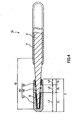
- Fig. 1 is a longitudinal sectional view showing the guide wire according to the first embodiment of the present invention.
- the right side and the left side in Fig. 1 are called “proximal portion” and “distal end,” respectively.
- proximal portion and distal end
- distal end respectively.
- Figs. 2 to 6 the guide wire is schematically shown, with its length shortened and its thickness exaggerated. Therefore, the ratio of thickness to length differs from the actual one.
- the guide wire 1 shown in Fig. 1 is a catheter guide wire or a transendoscopic guide wire which, at the time of use, is inserted into the lumen of a catheter (or an endoecope). It has the wire proper 2 which consists of a flexible or soft core wire (or an extended linear core). The wire proper 2 has a round shape in cross section.
- the wire proper 2 consists of one continuous core wire.
- the present invention also covers the wire proper 2 consisting of two or more core wires (of identical or different materials) welded together.
- the guide wire 1 should preferably have an overall length of about 200 to 5000 mm, which is not specifically restricted.
- the wire proper 2 consists of two parts, the first one having a uniform outside diameter and the second one gradually tapering off toward the distal end.
- the second part may taper off in more than one step.
- the wire proper 2 shown in Fig. 1 has at its distal end one tapering part 15.
- the tapering part 15 gradually decreases the flexural and torsional stiffness of the wire proper (core) 2 in going toward the distal end. This makes the guide wire 1 flexible at its distal end, which improves safety, permits the guide wire to track the blood vessel easily, and prevents the guide wire from bending.
- this tapering part 15 is where the radiopaque part 7 is arranged (mentioned later).
- the illustrated guide wire is so constructed as to have the tapering part 15 at the distal end (a portion in the lengthwise direction) of the wire proper 2; however, the tapering part 15 may extend over the entire length of the wire proper 2.
- the tapering part 15 may decrease in outside diameter evenly or unevenly in the lengthwise direction.
- the angle of taper may be Constant or variable from one position to another. In the latter case, steep taper and mild taper may repeat themselves more than once.
- the wire proper 2 has a uniform outside diameter along its length from the proximal point of the tapering part 15 to the proximal portion.
- the core wire of the wire proper 2 may be formed from any material selected from the following without specific restrictions.
- Stainless steel such as SUS304, SUS303, SUS302, SUS316, SUS316L, SUS316J1, SUS316J1L, SUS405, SUS430, SUS434, SUS444, SUS429, SUS430F, and SUS302), piano wire, iron-cobalt alloy, carbon steel (including low-carbon and ultra low-carbon steels), mild steel, hard steel, ferroalloy (such as nickel steel, nickel-chromium steel, and nickel-chromium-molybdenum steel), and other alloys (such as cobalt alloy, titanium alloy, and nickel alloy), of these examples, stainless steel is most desirable because of its higher strength and stiffness than the superelastic alloy mentioned later. It provides the guide wire 1 pushability and torque transmission performance.
- the core wire of the wire proper 2 may also be formed from any alloy which exhibits pseudoelasticity, such as superelastic alloy.
- Superelastic alloy is characterized by flexibility and elasticity (ability to recover itself from bending).
- flexibility and elasticity ability to recover itself from bending.
- the resulting guide wire 1 therefore, easily tracks the intricately winding and bending blood vessel. This leads to good steerability.
- the guide wire 1 is free of sustained bending that adversely affects its steerability.
- the pseudoelastic alloy includes those which give any stress-strain curve due to tensile force or those which may or may not have marked transformation temperatures (such as As, Af, Ms, and Mf). It includes any alloy which greatly deforms under stress and restores its original shape almost completely when stress is removed.
- Ni-Ti alloy containing 49 to 52 at% of Ni Ni-Ti alloy containing 49 to 52 at% of Ni.
- the Ni-T3 alloy is most desirable.
- the superelastic alloy typified by the Ni-Ti alloy is superior in adhesion to the surface layer 4 mentioned later.
- Cobalt alloy has a high modulus of elasticity and an adequate elastic limit. Therefore, the wire of cobalt alloy is superior in torque transmission performance and almost free of troubles such as buckling. No restrictions are imposed on the kind of cobalt alloy so long as the alloy contains cobalt. Those alloys in which cobalt dominates (Co-based alloy: the alloy which contains cobalt dominantly by weight percent) are desirable. Co-Ni-Cr alloys are most desirable. They will enhance the above-mentioned effect.
- alloys of such compositions are high in modulus of elasticity, and can be cold formed even when they are conditioned to have a high elastic limit, they permit the guide wire to be made thin while protecting it from buckling and they also impart good flexibility and stiffness necessary for the guide wire to be inserted into the desired position.
- the wire proper 2 may consist of two or more core wires of different materials joined together.
- it may consist of the first core wire (extending toward the distal end) and the second core wire (extending toward the proximal portion).
- the first core wire should preferably be made of superelastic alloy, particularly Ni-Ti alloy
- the second core wire should preferably be made of stainless steel (mentioned above).
- the boundary (or junction) between the first and second core wires may exist anywhere between the tapering part 15 and the proximal portion, at the proximal point of the tapering part 15, or anywhere in the tapering part 15.
- the distal end of the wire proper 2 (or the distal end of the first core wire) may have a shapeable part (not shown) which is shapeable.
- the wire proper 2 may have its surface treated for good adhesion to the surface layer 4 (mentioned later).
- the treatment includes surface roughening treatment, chemical treatment, and heat treatment.
- the guide wire 1 having the wire proper 2 has the radiopaque part 7 (that produces an X-ray image) at its distal end.
- the radiopaque part 7 consists of the coil 6 (which is radiopaque) surrounding the wire proper 2 and the resin coating layer 5 that covers the coil 6.
- the radiopaque part 7 is divided into three sections the first radiopaque region 71, the second radiopaque region 72, and the third radiopaque region 73, which are arranged from the distal end in the lengthwise direction. These three regions differ in the degree of opaqueness from one another. They also differ in length from one another in the lengthwise direction of the wire proper 2.
- the radiopaque part 7 has its distal end rounded to ensure the safety of the guide wire 1.
- the coil 6 surrounding the distal end of the wire proper 2 is a thin wire that helically winds around the wire proper 2 in its circumferential and lengthwise directions.
- the coil 6 consists of a single wire that continues from the first radiopaque region 71 to the third radiopaque region 73.
- This structure imparts good flexibility to the radiopaque part 7, thereby contributing to safety and ability to track the lumen.
- This structure also reduces the number of parts constituting the radiopaque part 7 and reduces the production cost of the guide wire 1.
- the coil 6 may be wound tightly, loosely, and tightly in going backward from the distal end.
- the advantage of this structure is that the radiopaque part 7 does not abruptly change in physical properties in its lengthwise direction.
- the coil 6 is made of a metallic material selected from noble metals (such as gold and platinum) and alloy thereof (such as platinum-iridium alloy) and tungsten. Thus, the coil 6 makes the guide wire 1 opaque to X-rays.
- noble metals such as gold and platinum
- alloy thereof such as platinum-iridium alloy
- the coil 6 is formed in such a way that its inside comes into close contact with the outside of the tapering part 15 of the wire proper 2.
- the coil 6 is formed from a wire having a round cross section; however, the wire may have a square (or rectangular) or elliptic cross section.
- the radiopaque part 7 contains the coating layer 5 that covers the coil 6.
- the coating layer 5 may be formed from any resin selected, without restrictions, from polyurethane, polyolefins (such as polyethylene, polypropylene, and ethylene-propylene copolymer), fluoroplastics (such as polytetrafluoroethylene), polyesters (such as polyethylene terephthalate), polyvinyl chloride, polyamide, polyimide, ethylene-vinyl acetate copolymer, ethylene-acrylonitrile-copolymer, ABS resin, AS resin, butadiene-styrene copolymer, polyisoprene, and polybutadiene.
- a material such as polyurethane which is comparatively highly flexible because of its flexibility and superiority in adhesion to the wire 2.
- the constituent of the coating layer 5 is partly incorporated with metal powder as a radiopaque radiopaque material.
- the metal powder may be that of tungsten or noble metal (such as gold and platinum), the former being preferable.
- the kind and content of the metal powder determine the opaqueness of the first to third radiopaque regions 71, 72, and 73 of the radiopaque part 7.
- the radiopaque material in the coating layer 5 should have a particle size of 0.5 to 4.0 ⁇ m, preferably 1.0 to 1.5 ⁇ m, which is not specifically restricted.
- the coating layer 5 may be of single-layer structure or multi-layer structure.
- the wire proper 2 has its outside surface covered partly or entirely with the surface layer 4.
- the surface layer 4 shown in Fig. 1 covers that region of the wire proper 2 which extends from the proximal point of the tapering part 15 to the proximal portion.
- the surface layer 4 has multiple purposes. One major purpose is to make the guide wire 1 easily slidable with reduced friction, so that the guide wire 1 improves in steerability.
- the surface layer 4 should preferably be formed from a fluoroplastic, which effectively reduces friction between the guide wire 1 and the inner wall of the catheter. This leads to improved slidability and steerability of the guide wire 1 in the catheter. In addition, reduced friction prevents the guide wire 1 from kinking and twisting which would otherwise occur (particularly near the welded part) when the guide wire 1 is moved or turned in the catheter.
- the fluoroplastic includes, for example, polytetrafluoroethylene (PTFE), tetrafluoroethylene-perfluoroalkylvinyl ether copolymer (PFA), polychlorotrifluoroethylene (PCTFE), polyvinylidene fluoride (PVDF), polyvinyl fluoride (PVF), tetrafluoroethylene-hexafluoropropylene copolymer (FEP), and tetrafluoroethylene-ethylene copolymer (PETFE). They may be used alone or in combination with one another.
- PTFE polytetrafluoroethylene
- PFA tetrafluoroethylene-perfluoroalkylvinyl ether copolymer
- PCTFE polychlorotrifluoroethylene
- PVDF polyvinylidene fluoride
- PVDF polyvinyl fluoride
- FEP tetrafluoroethylene-hexafluoropropylene copolymer
- the guide wire 1 has its surface (at least in the region of its distal end) coated with a hydrophilic material, which gets wet to reduce the friction of the guide wire 1. This results in the guide wire 1 improving in slidability and steerability.
- the hydrophilic material includes, for example, cellulosic polymer, polyethylene oxide, methylvinyl ether-maleic anhydride copolymer, polyacrylamide, polyglycidyl methacrylate-dimethylacrylamide block copolymer (PGMA-DMAA), water-soluble nylon, polyvinyl alcohol, and polyvinylpyrrolidone.
- cellulosic polymer polyethylene oxide, methylvinyl ether-maleic anhydride copolymer, polyacrylamide, polyglycidyl methacrylate-dimethylacrylamide block copolymer (PGMA-DMAA), water-soluble nylon, polyvinyl alcohol, and polyvinylpyrrolidone.
- the hydrophilic materials mentioned above usually absorb water or become moistened to reduce friction between the guide wire 1 and the inner wall of the catheter or endoscope. This produces the effect of improving the slidability and steerability of the guide wire 1.
- the radiopaque parts 7 is divided into the first to third radiopaque regions 71, 72, and 73.
- the second one has the least opaqueness among the three. Since the first and third ones are of the same structure, the difference in opaqueness will be explained below with reference to the first one.
- coil 6 is wound more densely in the second radiopaque region 72 than the first radiopaque region 71, in other words, the coil 6 is tightly wound in the first radiopaque region 71 and loosely wound in the second radiopaque region 72.
- the coating layer 5 in the radiopaque part 7 varies in the content of the radiopaque material from one region to another. That is, the coating layer 52 (that portion of the coating layer 5 corresponding to the second radiopaque region 72) contains a less amount of radiopaque material than the coating layer 51 (that portion of the coating layer 5 corresponding to the first radiopaque region 71).
- the radiopaque part 7 varies in opaqueness from the first radiopaque region 71 to the second radiopaque region 72 according to the winding pitch of the coil 6 and the content of the radiopaque material.
- the radiopaque part 7 has two regions (at its both ends), where opaqueness is high, and one region (at middle), where opaqueness is low.
- the radiopaque part 7 constructed as mentioned above produces the following effect.
- the radiopaque part 7 as a whole is opaque to X-rays and yet it varies in opaqueness from one region to another.
- the first radiopaque region 71 is more opaque
- the second radiopaque region 72 is less opaque
- the third region 73 is more opaque.
- the difference in opaqueness produces a high contrast.
- the highly contrasting opaqueness permits one to distinguish the distal end (the radiopaque part 7) from the other part of the guide wire 1.
- the difference in opaqueness permits one to recognize the three divided parts in the distal end of the guide wire 1. Therefore it is favorable to construct the radiopaque part 7.
- the second radiopaque region 72 enables one to identify (visually identify) the third radiopaque region 73 more certainly.
- the radiopaque regions varying in opaqueness permit one to accurately locate the distal end and other parts of the guide wire 1 being inserted into the lumen (such as bile duct) of a living body by radioscopy, in other words, this permits one to determine how far the guide wire 1 has advanced, consequently, the guide wire can be advanced into the lumen of a living body adequately. This prevents the guide wire 1 from moving from the desired position unexpectedly.
- the forgoing effect may not be produced if the radiopaque part 7 consists of the coil 6 or the radiopaque material alone. This depends on the intensity of X-rays.
- the coating layers 51 and 53 which contain more radiopaque material than the coating layer 52, make the coil 6 poor in adhesion to the wire proper 2 although this depends on the constituent of radiopaque material.
- the coating layer 72 of the radiopaque part 7 contains only a small quantity (or none) of radiopaque material and hence it firmly adheres to the coil 6 and the wire proper 2 or it helps the entire coating layer 7 to fix to the coil6 and the wire proper 2.
- the coating layers 71 to 73 are bonded together by mutual dissolution of resin materials, and they (as the entire coating layer 7) firmly fix to the coil 6 and the wire proper 2. This eliminates the necessity of fixing the coil 6 with the above-mentioned fixing material, thereby preventing the distal end of the guide wire 1 from becoming stiffer. In other words, the distal end of the guide wire 1 remains flexible.
- the coil 6 in the first radiopaque region 71 should be wound 3 to 7 times denser, preferably 4 to 7 times denser, that of the coil 6 in the second radiopaque region 72, although it is not specifically restricted.
- the content of radiopaque material in the coating layer 52 should be less than 10%, preferably less than 5%, of that in the coating layer 51, although it is not specifically restricted.
- the content may be zero.
- the radiopaque part 7 that produces a high contrast contributes to good steerability of the guide wire 1 being inserted into the desire position in the lumen.
- the first and third radiopaque regions 71 and 73 are almost identical in structure, and consequently they produce almost the same degree of contrast. This facilitates the fabrication of the radiopaque part 7.
- the first to third radiopaque regions 71, 72, and 73 are arranged in descending order of length. Specifically, the length (L1) of the first radiopaque region 71 is longer than the length (L2) of the second radiopaque region 72, the length (L2) of the second radiopaque region 72 is longer than the length (L3) of the third radiopaque region 73.
- the first radiopaque region 71 which is longest, can surely be inserted and permits the guide wire 1 to be inserted deep enough to avoid slipping out.
- the second and third radiopaque regions 72 and 73 serve as marks to lead the guide wire 1 to the desired position.
- the radiopaque regions differing in length and contrast help the rapid and accurate insertion by radioscopy.
- the length (L1) of the first radiopaque region 71 should be 10 to 80 mm; preferably 30 to 70 mm.
- the length (L2) of the second radiopaque region 72 should be 3 to 40 mm, preferably 10 to 20 mm.
- the length (L3) of the third radiopaque region 73 should be 1 to 20 mm, preferably 3 to 10 mm.
- the ratio of L2/L1 should be 0.1 to 0.7, preferably 0.2 to 0.6.
- the ratio of L3/L2 should be 0.1 to 1, preferably 0.2 to 1. These ratios are necessary to produce the above-mentioned effects.
- the coating layer 52 should preferably differ in color from the coating layers 51 and 53.
- the coating layer 52 should have a chromatic color (e.g., blue) and the coating layers 51 and 53 should have an achromatic color (e.g., black).
- This color arrangement makes it easy to determine how far the guide wire 1 has advanced by means of an endoscope. Endoscopic observation in combination with radioscopy permits one to accurately locate the distal end of the guide wire 1.
- the coloring of the coating layers 51 to 53 may be accomplished, for example, by incorporation of pigments into the resin material constituting each coating layer.
- the coating layers 51 to 53 which vary in the content of radiopaque material, may be formed in the following manner which is not specifically restricted.
- the wire proper 2 around which the coil 6 has been wound, is masked except for the parts where the coating layers 51 and 53 are to be formed.
- the resin material containing a radiopaque material is applied, except for the masked part, to form the coating layers 51 and 53.
- the mask is removed, and the coating layers 51 and 53 are masked.
- the resin material is applied, except for the masked parts, to form the coating layer 52. In this way the coating layers 51 to 53 are formed.
- the wire proper 2 is in contact with the inner surface of the coil 6. However, this is no essential.
- the tapering_part 15 of the wire proper 2 may simply pass through the coil 6 without contact with its inner surface.
- the coil 6 is formed from a single continuous wire wound around the first to third radiopaque regions 71 to 73.
- the coil 6 may consist of three separate coils joined together. In this case, the coils at both ends may be made of different materials.
- Fig. 2 is a longitudinal sectional view showing the guide wire according to the second embodiment of the present invention.
- the second embodiment is identical with the first one except for the structure of the radiopaque part.
- the radiopaque part 7A has the coating layer 5 which consists of three coating layers 51 to 53.
- the coating layers 51 to 53 contain substantially the same amount of the radiopaque material which is uniformly distributed therein, and there is no difference in the amount of radiopaque material in the coating layers 51 to 53. Therefore, the first and second radiopaque regions 71 and 72 differ in contrast only because the coil 6 is wound more densely in the second radiopaque region 72 than the first radiopaque region 71.
- the forgoing structure is effective in the case where it is desirable in radioscopy that the radiopaque part 7A should have a lower contrast than the radiopaque part 7 in the first embodiment.
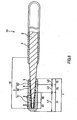
- Fig. 3 is a longitudinal sectional view showing the guide wire according to the third embodiment of the present invention.
- the third embodiment is identical with the first one except for the structure of the radiopaque part.
- the radiopaque part 7B has the coil 6 which is wound substantially uniformly (without pitch variation) throughout the first to third radiopaque regions 71 to 73.
- difference in opaqueness between the first radiopaque region 71 and the second radiopaque region 72 is due mainly to the fact that the coating layer 52 contains a less amount of radiopaque material than the coating layer 51.
- the forgoing structure is effective in the case where it is desirable in radioscopy that the radiopaque part 7B should have a lower contrast than the radiopaque part 7 in the first embodiment.
- Fig. 4 is a longitudinal sectional view showing the guide wire according to the fourth embodiment of the present invention.
- the fourth embodiment is identical with the first one except for the structure of the resin coating layer.
- the coating layers 51 to 53 contain almost the same amount of radiopaque material.
- the radiopaque material in the coating layer 52 is poorer in opaqueness than that in the coating layers 51 and 53.
- the difference in opaqueness and the difference in the winding pitch of the coil 6 produce a synergistic effect of distinguishing between the first radiopaque region 71 and the second radiopaque region 72. Therefore, as in the first embodiment, the radiopaque part 7 produces a good contrast in radioscopy.
- the guide wire 1C permits one to accurately locate it in the lumber of a living body.
- the coating layers 51 and 52 can be made to vary in opaqueness by incorporating them with a radiopaque material differing in composition.
- their radiopaque material may be tungsten and bismuth sulfide, respectively, or tungsten and barium sulfide, respectively.
- Fig. 5 is a longitudinal sectional view showing the guide wire according to the fifth embodiment of the present invention.
- the fifth embodiment is identical with the first one except for the shape of the distal end of the wire proper.
- the wire proper 2 has at its distal end the part 17 which has a uniform outside diameter and extends from the end of the tapering part 15 to the distal end.
- This structure makes the distal end of the wire proper 2 gradually decrease in stiffness in going toward the distal end.
- the guide wire 1D has good flexibility at its distal end and easily tracks the blood vessel without bending, which leads to greater safety.
- the radiopaque part 7 is so formed as to step over the part 17 (which has a uniform outside diameter) and a portion of the tapering part 15. It consists of the first to third radiopaque regions 71 to 73.
- the first radiopaque region 71 is in the part 17, and the second and third radiopaque regions 72 and 73 are in the tapering part 15.
- the part 17 is formed at the distal end of the wire proper 2; however, it may also be formed in any part of the wire proper 2 (for example, in the middle of the tapering part 15).
- the surface layer 4 covers the guide wire 1D entirely (from the distal end to the proximal portion). It reduces the friction (sliding resistance) of the guide wire 1 and improves slidability, which contributes to the steerability of the guide wire 1.
- Fig. 6 is a longitudinal sectional view showing the guide wire according to the sixth embodiment of the present invention.
- the sixth embodiment is identical with the first one except for the structure of the radiopaque member.
- the guide wire 1E shown in Fig. 6 has ringlike members 8 which are opaque to X-rays.
- the ringlike members are arranged in the lengthwise direction of the wire proper 2 and inserted on the tapering part 15 of the wire proper 2.
- An inner circumference surface of ringlike members 8 is intimately contacted with an outer circumference surface of the wire proper 2.
- the ringlike members 8 are arranged more closely, on average, in the second radiopaque region 72 than in the first and third radiopaque regions 71 and 73.
- the first radiopaque region 71 consists of subsections 81 and 82.
- the adjacent ringlike members 8 are in contact with one another.
- the adjacent ringlike members 8 are spaced from one another.
- the subsection 81 is closer to the distal end than the subsection 82.
- the guide wire 1B is characterized in that the ringlike members are arranged at intervals that vary from the first radiopaque region 71 to the second radiopaque region 72. This difference in intervals combined with the difference in the content of radiopaque material makes an apparent difference in opaqueness between the first radiopaque region 71 and the second radiopaque region 72.
- the radiopaque part 7 produces a good contrast as in the first embodiment. Owing to the radiopaque part 7 excelling in opaqueness and the radiopaque part 7 consisting of radiopaque regions differing in length, the guide wire 1E permits one to accurately locate its position by radioscopy at the time of its insertion into the lumen of a living body.
- the ringlike members 8 functioning as the radiopaque members in the guide wire 1E can be easily arranged at varying intervals.
- the ringlike members 8 may be formed from any material, which includes such material as used for the coil 6 in the first embodiment
- the ringlike members 8 have a square or rectangular cross section; however, the cross section may be round or elliptic.
- the guide wire according to the present invention has been described with reference to the illustrated embodiments.
- the present invention is not limited to them.
- the constituents of the guide wire may be replaced by those which have the same functions or may be modified with additional elements.
- the present invention may have any two or more structures (features) in combination selected from the foregoing embodiments.
- the guide wire according to the present invention is not limited to the one which is used for transendoscopic technique. It can also be used for therapy of CTO (chromic total occlusion) and angiography and PTCA (Percutaneous Transluminal Coronary Angioplasty).
- CTO chromic total occlusion
- PTCA Percutaneous Transluminal Coronary Angioplasty
- the radiopaque part has three radiopaque regions. However, it may have one or two additional ones next to the third one. In this case, the adjacent radiopaque regions should preferably differ in opaqueness from one another.
- the second radiopaque region is longer than the third one.
- both may have the same length.
- the radiopaque part has the radiopaque members and the coating layer. However, either of them may be omitted.
- the first and third radiopaque regions have approximately the same degree of opaqueness.
- the first region may have a higher or lower degree of opaqueness than the third one.
- the coating layer contains metal powder as a radiopaque material.
- the metal powder may be replaced by any metal oxide power opaque to X-rays.
- the metal oxide powder includes, for example, barium sulfide, bismuth oxide, and barium carbonate. Of those, the barium sulfide and the bismuth oxide are preferable. More than one kind of radiopaque material may be used in combination.
- the coating layer in the first and third radiopaque regions may contain tungsten power (metal powder) as a radiopaque material and the coating layer in the second radiopaque region may contain barium sulfate powder (metal oxide powder) as a radiopaque material.
Abstract
Description
- The present invention relates to a guide wire.
- A guide wire is used to facilitate insertion of a catheter into the lumen (such as digestive tract and blood vessel) of a living body. When in use, a catheter is slipped on it.
- A guide wire is also used to lead an endoscope or a catheter inserted into the lumen of an endoscope to a desired position in the lumen of a living body at the time of observation or treatment of the lumen of a living body (See Japanese Patent Laid-Open No.
2007-135645 US-A-5906981 andEP-B1-0759793 disclose guidewires according to the preamble of claim 1. - A guide wire for this purpose consists of a long wire proper and a coil covering the distal end of the wire proper. The coil may be formed from a radiopaque material such as noble metal. The coil makes the distal end of the guide wire visible to facilitate insertion of the guide wire into a living body by radioscopy. The coil consists of two parts (the first coil and the second coil), and each part is formed from a helically wound wire.
- The conventional coil consisting of two parts has the disadvantage of being recognized as one monochromatic continuous member in radioscopy with a certain intensity because the two parts are close to each other. This disadvantage causes difficulties in locating the distal end of the guide wire being inserted into the lumen of a living body.
- Moreover, the conventional coil alone does not produce a high-contrast X-ray image. This causes difficulties in locating the distal end of the guide wire and hence hinders smooth insertion of the guide wire into a living body. The fact that the guide wire is monochromatic and merely provides a low-contrast X-ray image makes it difficult to determine how far the guide wire has advanced and to locate the distal end of the guide wire being inserted into a living body.
- It is an object of the present invention to provide a guide wire which produces a high-contrast X-ray image and facilitates its location at the time of insertion into the lumen of a living body.
- The foregoing object is achieved by the present invention as defined in the appended claims.
- It is desirable that the length L1 should be 10 to 80 mm and the length L2 should be 3 to 40 mm.
- It is desirable that the difference in capability of forming an X-ray image between the first radiopaque region and the second radiopaque region should be due to the fact that the radiopaque members in the second radiopaque region are arranged less densely than that in the first radiopaque region.
- It is desirable that the difference in capability of forming an X-ray image between the first radiopaque region and the second radiopaque region should be due to the fact that the resin coating layer in the second radiopaque region contains a less amount of radiopaque material than the resin coating layer in the first radiopaque region.
- It is desirable that the difference in capability of forming an X-ray image between the first radiopaque region and the second radiopaque region should be due to the fact that the radiopaque members in the second radiopaque region are arranged less densely than that in the first radiopaque region and that the resin coating layer in the second radiopaque region contains a less amount of radiopaque material than the resin coating layer in the first radiopaque region.
- It is desirable that the difference in capability of forming an X-ray image between the first radiopaque region and the second radiopaque region should be due to the fact that the radiopaque members in the second radiopaque region are arranged less densely than that in the first radiopaque region and that the resin coating layer in the second radiopaque region is less capable of forming an X-ray image than the resin coating layer in the first radiopaque region.
- It is desirable that the radiopaque material should be particles of a metallic material or a metal oxide.
- It is desirable that the content of the radiopaque material in the resin coating layer in the second radiopaque region should be less than 10% of the content of the radiopaque material in the resin coating layer in the first radiopaque region and the third radiopaque region.
- It is desirable that the radiopaque member should be a helically wound coil which is wound more density in the second radiopaque region than the first radiopaque region.
- It is desirable that the coil should be formed from a single filamentous body that extends from the first radiopaque region to the third radiopaque region.
- It is desirable that the radiopaque member should take on a ringlike shape and a plurality of the radiopaque members should be arranged in the lengthwise direction of the wire proper, and adjacent radiopaque members should be arranged more densely in the second radiopaque region than in the first radiopaque region.
- It is desirable that the radiopaque member in the first and third radiopaque regions should be arranged 3 to 7 times as densely as the radiopaque member_in the second radiopaque region.
- It is desirable that the resin coating layer in the second radiopaque region should differ in color from that in either of the first radiopaque region and the third radiopaque region.
- It is desirable that the radiopaque part should be in close contact with the wire proper.
- It is desirable that that part of the wire proper where the radiopaque part is arranged should be at least partly tapered in such a way that the outside diameter gradually decreases in going toward the distal end.
- According to the present invention, the radiopaque part is capable of forming an X-ray image with a varying degree of opaqueness depending on its positions (the first to third radiopaque regions). The difference in opaqueness produces a high contrast. This permits one to distinguish the distal part of the guide wire from other parts of the guide wire and to recognize at least the three regions in the distal part, when the guide wire is being inserted into the lumen of a living body by radioscopy. The recognition of the three regions permits one to accurately locate the guide wire being inserted into the lumen of a living body. For example, this permits one to prevent the guide wire from slipping off unexpectedly.
- The first radiopaque region is longer than the second radiopaque region, and the second radiopaque region is equal to or longer than the third radiopaque region. This, in combination the radiopaque regions differing in opaqueness, permits one to accurately and rapidly operate the guide wire and to locate the position of the guide wire being inserted into the lumen of a living body, consequently, the guide wire can be advanced into the lumen of a living body adequately. The first radiopaque region (longest) which enters first the lumen helps one to distinguish it from other radiopaque regions. This permits one to accurately locate the guide wire.
- The first radiopaque region may be longer than the second radiopaque region and the second radiopaque region may be equal to or longer than the third radiopaque region. This permits one to accurately locate the guide wire being inserted into the lumen of a living body, consequently, the guide wire can be advanced into the lumen of a living body adequately.
-
Fig. 1 is a longitudinal sectional view showing the guide wire according to the first embodiment of the present invention; -
Fig. 2 is a longitudinal sectional view showing the guide wire according to the second embodiment of the present invention; -
Fig. 3 is a longitudinal sectional view showing the guide wire according to the third embodiment of the present invention; -
Fig. 4 is a longitudinal sectional view showing the guide wire according to the fourth embodiment of the present invention; -
Fig. 5 is a longitudinal sectional view showing the guide wire according to the fifth embodiment of the present invention; -
Fig. 6 is a longitudinal sectional view showing the guide wire according to the sixth embodiment of the present invention. - The guide wire according to the present invention will be described in more detail with reference to the accompanying drawings.
-
Fig. 1 is a longitudinal sectional view showing the guide wire according to the first embodiment of the present invention. For convenience' sake of explanation, the right side and the left side inFig. 1 are called "proximal portion" and "distal end," respectively. This also applies toFigs. 2 to 6 . For easy understanding, inFig. 1 (this also applies toFigs. 2 to 6 ), the guide wire is schematically shown, with its length shortened and its thickness exaggerated. Therefore, the ratio of thickness to length differs from the actual one. - The guide wire 1 shown in
Fig. 1 is a catheter guide wire or a transendoscopic guide wire which, at the time of use, is inserted into the lumen of a catheter (or an endoecope). It has the wire proper 2 which consists of a flexible or soft core wire (or an extended linear core). The wire proper 2 has a round shape in cross section. - According to this embodiment, the wire proper 2 consists of one continuous core wire. However, the present invention also covers the wire proper 2 consisting of two or more core wires (of identical or different materials) welded together.
- The guide wire 1 should preferably have an overall length of about 200 to 5000 mm, which is not specifically restricted.
- According to this embodiment, the wire proper 2 consists of two parts, the first one having a uniform outside diameter and the second one gradually tapering off toward the distal end. The second part may taper off in more than one step. The wire proper 2 shown in
Fig. 1 has at its distal end one taperingpart 15. - The tapering
part 15 gradually decreases the flexural and torsional stiffness of the wire proper (core) 2 in going toward the distal end. This makes the guide wire 1 flexible at its distal end, which improves safety, permits the guide wire to track the blood vessel easily, and prevents the guide wire from bending. Incidentally, this taperingpart 15 is where theradiopaque part 7 is arranged (mentioned later). - The illustrated guide wire is so constructed as to have the tapering
part 15 at the distal end (a portion in the lengthwise direction) of the wire proper 2; however, the taperingpart 15 may extend over the entire length of the wire proper 2. The taperingpart 15 may decrease in outside diameter evenly or unevenly in the lengthwise direction. In other words, the angle of taper may be Constant or variable from one position to another. In the latter case, steep taper and mild taper may repeat themselves more than once. - The wire proper 2 has a uniform outside diameter along its length from the proximal point of the tapering
part 15 to the proximal portion. - The core wire of the wire proper 2 may be formed from any material selected from the following without specific restrictions. Stainless steel (such as SUS304, SUS303, SUS302, SUS316, SUS316L, SUS316J1, SUS316J1L, SUS405, SUS430, SUS434, SUS444, SUS429, SUS430F, and SUS302), piano wire, iron-cobalt alloy, carbon steel (including low-carbon and ultra low-carbon steels), mild steel, hard steel, ferroalloy (such as nickel steel, nickel-chromium steel, and nickel-chromium-molybdenum steel), and other alloys (such as cobalt alloy, titanium alloy, and nickel alloy), of these examples, stainless steel is most desirable because of its higher strength and stiffness than the superelastic alloy mentioned later. It provides the guide wire 1 pushability and torque transmission performance.
- The core wire of the wire proper 2 may also be formed from any alloy which exhibits pseudoelasticity, such as superelastic alloy.
- Superelastic alloy is characterized by flexibility and elasticity (ability to recover itself from bending). Thus, when applied to the wire proper 2, it makes the distal portion of the guide wire 1 sufficiently flexible and capable of restoration. The resulting guide wire 1, therefore, easily tracks the intricately winding and bending blood vessel. This leads to good steerability. In addition, because the wire proper 2 easily recovers itself from bending, the guide wire 1 is free of sustained bending that adversely affects its steerability.
- The pseudoelastic alloy includes those which give any stress-strain curve due to tensile force or those which may or may not have marked transformation temperatures (such as As, Af, Ms, and Mf). It includes any alloy which greatly deforms under stress and restores its original shape almost completely when stress is removed.
- Some desirable examples of the supérelastic alloy are listed below. Ni-Ti alloy containing 49 to 52 at% of Ni. Cu-Zn alloy containing 38.5 to 41.5 wt% of Zn. Cu-Zn-X alloy containing 1 to 10 wt% of X (where X is at least one species selected from Be, Si, Sn, A1, and Ga). Ni-Al alloy containing 36 to 38 at% of Al. Of these examples, the Ni-T3 alloy is most desirable. Incidentally, the superelastic alloy typified by the Ni-Ti alloy is superior in adhesion to the surface layer 4 mentioned later.
- Cobalt alloy has a high modulus of elasticity and an adequate elastic limit. Therefore, the wire of cobalt alloy is superior in torque transmission performance and almost free of troubles such as buckling. No restrictions are imposed on the kind of cobalt alloy so long as the alloy contains cobalt. Those alloys in which cobalt dominates (Co-based alloy: the alloy which contains cobalt dominantly by weight percent) are desirable. Co-Ni-Cr alloys are most desirable. They will enhance the above-mentioned effect. Besides, because alloys of such compositions are high in modulus of elasticity, and can be cold formed even when they are conditioned to have a high elastic limit, they permit the guide wire to be made thin while protecting it from buckling and they also impart good flexibility and stiffness necessary for the guide wire to be inserted into the desired position.
- As mentioned above, the wire proper 2 may consist of two or more core wires of different materials joined together. For example, it may consist of the first core wire (extending toward the distal end) and the second core wire (extending toward the proximal portion). In this case, the first core wire should preferably be made of superelastic alloy, particularly Ni-Ti alloy, and the second core wire should preferably be made of stainless steel (mentioned above). The boundary (or junction) between the first and second core wires may exist anywhere between the tapering
part 15 and the proximal portion, at the proximal point of the taperingpart 15, or anywhere in the taperingpart 15. - The distal end of the wire proper 2 (or the distal end of the first core wire) may have a shapeable part (not shown) which is shapeable.
- The wire proper 2 may have its surface treated for good adhesion to the surface layer 4 (mentioned later). The treatment includes surface roughening treatment, chemical treatment, and heat treatment.
- As shown in
Fig. 1 , the guide wire 1 having the wire proper 2 has the radiopaque part 7 (that produces an X-ray image) at its distal end. Theradiopaque part 7 consists of the coil 6 (which is radiopaque) surrounding the wire proper 2 and theresin coating layer 5 that covers thecoil 6. Theradiopaque part 7 is divided into three sections the firstradiopaque region 71, the secondradiopaque region 72, and the thirdradiopaque region 73, which are arranged from the distal end in the lengthwise direction. These three regions differ in the degree of opaqueness from one another. They also differ in length from one another in the lengthwise direction of the wire proper 2. - The
radiopaque part 7 has its distal end rounded to ensure the safety of the guide wire 1. - The
coil 6 surrounding the distal end of the wire proper 2 is a thin wire that helically winds around the wire proper 2 in its circumferential and lengthwise directions. Thecoil 6 consists of a single wire that continues from the firstradiopaque region 71 to the thirdradiopaque region 73. This structure imparts good flexibility to theradiopaque part 7, thereby contributing to safety and ability to track the lumen. This structure also reduces the number of parts constituting theradiopaque part 7 and reduces the production cost of the guide wire 1. Thecoil 6 may be wound tightly, loosely, and tightly in going backward from the distal end. The advantage of this structure is that theradiopaque part 7 does not abruptly change in physical properties in its lengthwise direction. - The
coil 6 is made of a metallic material selected from noble metals (such as gold and platinum) and alloy thereof (such as platinum-iridium alloy) and tungsten. Thus, thecoil 6 makes the guide wire 1 opaque to X-rays. - The
coil 6 is formed in such a way that its inside comes into close contact with the outside of the taperingpart 15 of the wire proper 2. - In this embodiment, the
coil 6 is formed from a wire having a round cross section; however, the wire may have a square (or rectangular) or elliptic cross section. - The
radiopaque part 7 contains thecoating layer 5 that covers thecoil 6. Thecoating layer 5 may be formed from any resin selected, without restrictions, from polyurethane, polyolefins (such as polyethylene, polypropylene, and ethylene-propylene copolymer), fluoroplastics (such as polytetrafluoroethylene), polyesters (such as polyethylene terephthalate), polyvinyl chloride, polyamide, polyimide, ethylene-vinyl acetate copolymer, ethylene-acrylonitrile-copolymer, ABS resin, AS resin, butadiene-styrene copolymer, polyisoprene, and polybutadiene. Preferable among them is a material such as polyurethane which is comparatively highly flexible because of its flexibility and superiority in adhesion to thewire 2.. - The constituent of the
coating layer 5 is partly incorporated with metal powder as a radiopaque radiopaque material. The metal powder may be that of tungsten or noble metal (such as gold and platinum), the former being preferable. The kind and content of the metal powder determine the opaqueness of the first to thirdradiopaque regions radiopaque part 7. - The radiopaque material in the
coating layer 5 should have a particle size of 0.5 to 4.0 µm, preferably 1.0 to 1.5 µm, which is not specifically restricted. - The
coating layer 5 may be of single-layer structure or multi-layer structure. - The wire proper 2 has its outside surface covered partly or entirely with the surface layer 4. The surface layer 4 shown in
Fig. 1 covers that region of the wire proper 2 which extends from the proximal point of the taperingpart 15 to the proximal portion. The surface layer 4 has multiple purposes. One major purpose is to make the guide wire 1 easily slidable with reduced friction, so that the guide wire 1 improves in steerability. - The surface layer 4 should preferably be formed from a fluoroplastic, which effectively reduces friction between the guide wire 1 and the inner wall of the catheter. This leads to improved slidability and steerability of the guide wire 1 in the catheter. In addition, reduced friction prevents the guide wire 1 from kinking and twisting which would otherwise occur (particularly near the welded part) when the guide wire 1 is moved or turned in the catheter.
- The fluoroplastic includes, for example, polytetrafluoroethylene (PTFE), tetrafluoroethylene-perfluoroalkylvinyl ether copolymer (PFA), polychlorotrifluoroethylene (PCTFE), polyvinylidene fluoride (PVDF), polyvinyl fluoride (PVF), tetrafluoroethylene-hexafluoropropylene copolymer (FEP), and tetrafluoroethylene-ethylene copolymer (PETFE). They may be used alone or in combination with one another.
- The guide wire 1 has its surface (at least in the region of its distal end) coated with a hydrophilic material, which gets wet to reduce the friction of the guide wire 1. This results in the guide wire 1 improving in slidability and steerability.
- The hydrophilic material includes, for example, cellulosic polymer, polyethylene oxide, methylvinyl ether-maleic anhydride copolymer, polyacrylamide, polyglycidyl methacrylate-dimethylacrylamide block copolymer (PGMA-DMAA), water-soluble nylon, polyvinyl alcohol, and polyvinylpyrrolidone.
- The hydrophilic materials mentioned above usually absorb water or become moistened to reduce friction between the guide wire 1 and the inner wall of the catheter or endoscope. This produces the effect of improving the slidability and steerability of the guide wire 1.
- Now, as mentioned_above, the
radiopaque parts 7 is divided into the first to thirdradiopaque regions - As shown in
Fig. 1 ,coil 6 is wound more densely in the secondradiopaque region 72 than the firstradiopaque region 71, in other words, thecoil 6 is tightly wound in the firstradiopaque region 71 and loosely wound in the secondradiopaque region 72. - Moreover, the
coating layer 5 in theradiopaque part 7 varies in the content of the radiopaque material from one region to another. That is, the coating layer 52 (that portion of thecoating layer 5 corresponding to the second radiopaque region 72) contains a less amount of radiopaque material than the coating layer 51 (that portion of thecoating layer 5 corresponding to the first radiopaque region 71). - In this way, the
radiopaque part 7 varies in opaqueness from the firstradiopaque region 71 to the secondradiopaque region 72 according to the winding pitch of thecoil 6 and the content of the radiopaque material. Thus, theradiopaque part 7 has two regions (at its both ends), where opaqueness is high, and one region (at middle), where opaqueness is low. - The
radiopaque part 7 constructed as mentioned above produces the following effect. - The
radiopaque part 7 as a whole is opaque to X-rays and yet it varies in opaqueness from one region to another. The firstradiopaque region 71 is more opaque, the secondradiopaque region 72 is less opaque, and thethird region 73 is more opaque. The difference in opaqueness produces a high contrast. The highly contrasting opaqueness permits one to distinguish the distal end (the radiopaque part 7) from the other part of the guide wire 1. Moreover, the difference in opaqueness permits one to recognize the three divided parts in the distal end of the guide wire 1. Therefore it is favorable to construct theradiopaque part 7. The secondradiopaque region 72 enables one to identify (visually identify) the thirdradiopaque region 73 more certainly. - The radiopaque regions varying in opaqueness permit one to accurately locate the distal end and other parts of the guide wire 1 being inserted into the lumen (such as bile duct) of a living body by radioscopy, in other words, this permits one to determine how far the guide wire 1 has advanced, consequently, the guide wire can be advanced into the lumen of a living body adequately. This prevents the guide wire 1 from moving from the desired position unexpectedly.
- The forgoing effect may not be produced if the
radiopaque part 7 consists of thecoil 6 or the radiopaque material alone. This depends on the intensity of X-rays. - According to the conventional technology, it is necessary to fix the
coil 6 to the wire proper 2 with solder or adhesive, and the resultant fixing part becomes stiffer than the other parts. Moreover, the coating layers 51 and 53, which contain more radiopaque material than thecoating layer 52, make thecoil 6 poor in adhesion to the wire proper 2 although this depends on the constituent of radiopaque material. - In the guide wire 1 according to the present invention, however, the
coating layer 72 of theradiopaque part 7 contains only a small quantity (or none) of radiopaque material and hence it firmly adheres to thecoil 6 and the wire proper 2 or it helps theentire coating layer 7 to fix to the coil6 and the wire proper 2. In addition, the coating layers 71 to 73 are bonded together by mutual dissolution of resin materials, and they (as the entire coating layer 7) firmly fix to thecoil 6 and the wire proper 2. This eliminates the necessity of fixing thecoil 6 with the above-mentioned fixing material, thereby preventing the distal end of the guide wire 1 from becoming stiffer. In other words, the distal end of the guide wire 1 remains flexible. - The
coil 6 in the firstradiopaque region 71 should be wound 3 to 7 times denser, preferably 4 to 7 times denser, that of thecoil 6 in the secondradiopaque region 72, although it is not specifically restricted. - The content of radiopaque material in the
coating layer 52 should be less than 10%, preferably less than 5%, of that in thecoating layer 51, although it is not specifically restricted. The content may be zero. - The
radiopaque part 7 that produces a high contrast contributes to good steerability of the guide wire 1 being inserted into the desire position in the lumen. - As mentioned above, the first and third
radiopaque regions radiopaque part 7. - As shown in
Fig. 1 , the first to thirdradiopaque regions radiopaque region 71 is longer than the length (L2) of the secondradiopaque region 72, the length (L2) of the secondradiopaque region 72 is longer than the length (L3) of the thirdradiopaque region 73. When the guide wire 1 is inserted into the lumen of a living body, the firstradiopaque region 71, which is longest, can surely be inserted and permits the guide wire 1 to be inserted deep enough to avoid slipping out. The second and thirdradiopaque regions - The length (L1) of the first
radiopaque region 71 should be 10 to 80 mm; preferably 30 to 70 mm. The length (L2) of the secondradiopaque region 72 should be 3 to 40 mm, preferably 10 to 20 mm. The length (L3) of the thirdradiopaque region 73 should be 1 to 20 mm, preferably 3 to 10 mm. - The ratio of L2/L1 should be 0.1 to 0.7, preferably 0.2 to 0.6. The ratio of L3/L2 should be 0.1 to 1, preferably 0.2 to 1. These ratios are necessary to produce the above-mentioned effects.
- The
coating layer 52 should preferably differ in color from the coating layers 51 and 53. For example, thecoating layer 52 should have a chromatic color (e.g., blue) and the coating layers 51 and 53 should have an achromatic color (e.g., black). This color arrangement makes it easy to determine how far the guide wire 1 has advanced by means of an endoscope. Endoscopic observation in combination with radioscopy permits one to accurately locate the distal end of the guide wire 1. - The coloring of the coating layers 51 to 53 may be accomplished, for example, by incorporation of pigments into the resin material constituting each coating layer.
- The coating layers 51 to 53, which vary in the content of radiopaque material, may be formed in the following manner which is not specifically restricted.
- The wire proper 2, around which the
coil 6 has been wound, is masked except for the parts where the coating layers 51 and 53 are to be formed. The resin material containing a radiopaque material is applied, except for the masked part, to form the coating layers 51 and 53. - The mask is removed, and the coating layers 51 and 53 are masked. The resin material is applied, except for the masked parts, to form the
coating layer 52. In this way the coating layers 51 to 53 are formed. - According to this embodiment, the wire proper 2 is in contact with the inner surface of the
coil 6. However, this is no essential. Thetapering_part 15 of the wire proper 2 may simply pass through thecoil 6 without contact with its inner surface. - According to this embodiment, the
coil 6 is formed from a single continuous wire wound around the first to thirdradiopaque regions 71 to 73. However, this is not essential. Thecoil 6 may consist of three separate coils joined together. In this case, the coils at both ends may be made of different materials. -
Fig. 2 is a longitudinal sectional view showing the guide wire according to the second embodiment of the present invention. - The second embodiment will be described below with reference to
Fig. 2 . Emphasis is placed on the difference from the first embodiment mentioned above, and description of the same matter is not repeated. - The second embodiment is identical with the first one except for the structure of the radiopaque part.
- In the
guide wire 1A shown inFig. 2 , theradiopaque part 7A has thecoating layer 5 which consists of threecoating layers 51 to 53. The coating layers 51 to 53 contain substantially the same amount of the radiopaque material which is uniformly distributed therein, and there is no difference in the amount of radiopaque material in the coating layers 51 to 53. Therefore, the first and secondradiopaque regions coil 6 is wound more densely in the secondradiopaque region 72 than the firstradiopaque region 71. - The forgoing structure is effective in the case where it is desirable in radioscopy that the
radiopaque part 7A should have a lower contrast than theradiopaque part 7 in the first embodiment. -
Fig. 3 is a longitudinal sectional view showing the guide wire according to the third embodiment of the present invention. - The third embodiment will be described below with reference to
Fig. 3 . Emphasis is placed on the difference from the first embodiment mentioned above, and description of the same matter is not repeated. - The third embodiment is identical with the first one except for the structure of the radiopaque part.
- In the guide wire 1B shown in
Fig. 3 , theradiopaque part 7B has thecoil 6 which is wound substantially uniformly (without pitch variation) throughout the first to thirdradiopaque regions 71 to 73. Thus, in theradiopaque part 7B, difference in opaqueness between the firstradiopaque region 71 and the secondradiopaque region 72 is due mainly to the fact that thecoating layer 52 contains a less amount of radiopaque material than thecoating layer 51. - The forgoing structure is effective in the case where it is desirable in radioscopy that the
radiopaque part 7B should have a lower contrast than theradiopaque part 7 in the first embodiment. -
Fig. 4 is a longitudinal sectional view showing the guide wire according to the fourth embodiment of the present invention. - The fourth embodiment will be described below with reference to
Fig. 4 . Emphasis is placed on the difference from the first embodiment mentioned above, and description of the same matter is not repeated. - The fourth embodiment is identical with the first one except for the structure of the resin coating layer.
- In the
guide wire 1C shown inFig. 4 , the coating layers 51 to 53 contain almost the same amount of radiopaque material. However, the radiopaque material in thecoating layer 52 is poorer in opaqueness than that in the coating layers 51 and 53. The difference in opaqueness and the difference in the winding pitch of thecoil 6 produce a synergistic effect of distinguishing between the firstradiopaque region 71 and the secondradiopaque region 72. Therefore, as in the first embodiment, theradiopaque part 7 produces a good contrast in radioscopy. On account of theradiopaque part 7 which produces a good contrast and has the radiopaque regions varying in length, theguide wire 1C permits one to accurately locate it in the lumber of a living body. - The coating layers 51 and 52 can be made to vary in opaqueness by incorporating them with a radiopaque material differing in composition. For example, their radiopaque material may be tungsten and bismuth sulfide, respectively, or tungsten and barium sulfide, respectively.
-
Fig. 5 is a longitudinal sectional view showing the guide wire according to the fifth embodiment of the present invention. - The fifth embodiment will be described below with reference to
Fig. 5 . Emphasis is placed on the difference from the first embodiment mentioned above, and description of the same matter is not repeated. - The fifth embodiment is identical with the first one except for the shape of the distal end of the wire proper.
- In the
guide wire 1D shown inFig. 5 , the wire proper 2 has at its distal end thepart 17 which has a uniform outside diameter and extends from the end of the taperingpart 15 to the distal end. This structure makes the distal end of the wire proper 2 gradually decrease in stiffness in going toward the distal end. As the result, theguide wire 1D has good flexibility at its distal end and easily tracks the blood vessel without bending, which leads to greater safety. - The
radiopaque part 7 is so formed as to step over the part 17 (which has a uniform outside diameter) and a portion of the taperingpart 15. It consists of the first to thirdradiopaque regions 71 to 73. The firstradiopaque region 71 is in thepart 17, and the second and thirdradiopaque regions part 15. - In the case shown in
Fig. 5 , thepart 17 is formed at the distal end of the wire proper 2; however, it may also be formed in any part of the wire proper 2 (for example, in the middle of the tapering part 15). - The surface layer 4 covers the
guide wire 1D entirely (from the distal end to the proximal portion). It reduces the friction (sliding resistance) of the guide wire 1 and improves slidability, which contributes to the steerability of the guide wire 1. -
Fig. 6 is a longitudinal sectional view showing the guide wire according to the sixth embodiment of the present invention. - The sixth embodiment will be described below with reference to
Fig. 6 . Emphasis is placed on the difference from the first embodiment mentioned above, and description of the same matter is not repeated. - The sixth embodiment is identical with the first one except for the structure of the radiopaque member.
- The
guide wire 1E shown inFig. 6 has ringlikemembers 8 which are opaque to X-rays. The ringlike members are arranged in the lengthwise direction of the wire proper 2 and inserted on the taperingpart 15 of the wire proper 2. An inner circumference surface ofringlike members 8 is intimately contacted with an outer circumference surface of the wire proper 2. - The
ringlike members 8 are arranged more closely, on average, in the secondradiopaque region 72 than in the first and thirdradiopaque regions radiopaque region 71 consists ofsubsections subsection 81, the adjacentringlike members 8 are in contact with one another. In thesubsection 82, the adjacentringlike members 8 are spaced from one another. Thesubsection 81 is closer to the distal end than thesubsection 82. - The guide wire 1B is characterized in that the ringlike members are arranged at intervals that vary from the first
radiopaque region 71 to the secondradiopaque region 72. This difference in intervals combined with the difference in the content of radiopaque material makes an apparent difference in opaqueness between the firstradiopaque region 71 and the secondradiopaque region 72. Thus theradiopaque part 7 produces a good contrast as in the first embodiment. Owing to theradiopaque part 7 excelling in opaqueness and theradiopaque part 7 consisting of radiopaque regions differing in length, theguide wire 1E permits one to accurately locate its position by radioscopy at the time of its insertion into the lumen of a living body. - The
ringlike members 8 functioning as the radiopaque members in theguide wire 1E can be easily arranged at varying intervals. - The
ringlike members 8 may be formed from any material, which includes such material as used for thecoil 6 in the first embodiment - In this embodiment, the
ringlike members 8 have a square or rectangular cross section; however, the cross section may be round or elliptic. - In the foregoing, the guide wire according to the present invention has been described with reference to the illustrated embodiments. The present invention is not limited to them. The constituents of the guide wire may be replaced by those which have the same functions or may be modified with additional elements.
- The present invention may have any two or more structures (features) in combination selected from the foregoing embodiments.
- The guide wire according to the present invention is not limited to the one which is used for transendoscopic technique. It can also be used for therapy of CTO (chromic total occlusion) and angiography and PTCA (Percutaneous Transluminal Coronary Angioplasty).
- According to the foregoing embodiments, the radiopaque part has three radiopaque regions. However, it may have one or two additional ones next to the third one. In this case, the adjacent radiopaque regions should preferably differ in opaqueness from one another.
- According to the foregoing embodiments, the second radiopaque region is longer than the third one. However, both may have the same length.
- According to the foregoing embodiments, the radiopaque part has the radiopaque members and the coating layer. However, either of them may be omitted.
- According to the foregoing embodiments, the first and third radiopaque regions have approximately the same degree of opaqueness. However, the first region may have a higher or lower degree of opaqueness than the third one.
- According to the foregoing embodiments, the coating layer contains metal powder as a radiopaque material. However, the metal powder may be replaced by any metal oxide power opaque to X-rays. The metal oxide powder includes, for example, barium sulfide, bismuth oxide, and barium carbonate. Of those, the barium sulfide and the bismuth oxide are preferable. More than one kind of radiopaque material may be used in combination. For example, the coating layer in the first and third radiopaque regions may contain tungsten power (metal powder) as a radiopaque material and the coating layer in the second radiopaque region may contain barium sulfate powder (metal oxide powder) as a radiopaque material.
- It should be understood by those skilled in the art that various modifications, combinations, subcombinations and alterations may occur depending on design requirements and other factor in so far as they are within the scope of the appended claims.
Claims (4)
- A guide wire (1) having a long wire proper (2) and also having a radiopaque part (7) capable of forming an X-ray image formed at the distal end thereof,
said radiopaque part (7) having a first radiopaque region (71), a second radiopaque region (72), and a third radiopaque region (73) which are arranged sequentially from the distal end in the lengthwise direction thereof,
said second radiopaque region (72) being less capable of forming an X-ray image than either of said first radiopaque region (71) and said third radiopaque region (73),
characterized by
said first radiopaque region (71) having a length L1, said second radiopaque region (72) having a length L2, and said third radiopaque region (73) having a length L3 such that L1> L2≥ L3,
said radiopaque part (7) having a radiopaque member (6, 8) which is arranged around said wire proper (2) in the lengthwise direction thereof and is formed from a metallic material capable of forming an X-ray image, and a resin coating layer (5) which covers said radiopaque member (6, 8) and contains at least partly a radiopaque material capable of forming an X-ray image. - The guide wire (1) as defined in Claim 1, wherein the ratio of L2/L1 is 0.1 to 0.7.
- The guide wire (1) as defined in Claim 1, wherein the ratio of L3/L2 is 0.1 to 1.
- The guide wire (1) as defined in Claim 1, wherein said first radiopaque region (71) and said third radiopaque region (73) are equal to each other in capability of forming an X-ray image.
Applications Claiming Priority (3)
| Application Number | Priority Date | Filing Date | Title |
|---|---|---|---|
| JP2007340858A JP5430065B2 (en) | 2007-12-28 | 2007-12-28 | Guide wire |
| JP2008015575A JP5354916B2 (en) | 2008-01-25 | 2008-01-25 | Transendoscopic guidewire |
| EP08172416A EP2075030B1 (en) | 2007-12-28 | 2008-12-19 | Guide wire |
Related Parent Applications (1)
| Application Number | Title | Priority Date | Filing Date |
|---|---|---|---|
| EP08172416.3 Division | 2008-12-19 |
Publications (2)
| Publication Number | Publication Date |
|---|---|
| EP2158933A1 EP2158933A1 (en) | 2010-03-03 |
| EP2158933B1 true EP2158933B1 (en) | 2012-03-21 |
Family
ID=40474183
Family Applications (2)
| Application Number | Title | Priority Date | Filing Date |
|---|---|---|---|
| EP08172416A Active EP2075030B1 (en) | 2007-12-28 | 2008-12-19 | Guide wire |
| EP09179184A Active EP2158933B1 (en) | 2007-12-28 | 2008-12-19 | Guide wire |
Family Applications Before (1)
| Application Number | Title | Priority Date | Filing Date |
|---|---|---|---|
| EP08172416A Active EP2075030B1 (en) | 2007-12-28 | 2008-12-19 | Guide wire |
Country Status (5)
| Country | Link |
|---|---|
| US (1) | US8827926B2 (en) |
| EP (2) | EP2075030B1 (en) |
| AT (2) | ATE550065T1 (en) |
| DE (1) | DE602008001430D1 (en) |
| ES (1) | ES2379911T3 (en) |
Families Citing this family (18)
| Publication number | Priority date | Publication date | Assignee | Title |
|---|---|---|---|---|
| JP4913180B2 (en) * | 2009-07-02 | 2012-04-11 | 株式会社パテントストラ | Medical guide wire, method for manufacturing the same, and assembly of medical guide wire, balloon catheter, and guiding catheter |
| JP4913198B2 (en) * | 2009-10-27 | 2012-04-11 | 株式会社パテントストラ | Medical guide wire, method for manufacturing medical guide wire, assembly of medical guide wire, microcatheter and guiding catheter, and assembly of medical guide wire, balloon catheter and guiding catheter |
| EP2554210B1 (en) * | 2010-03-26 | 2019-01-16 | Terumo Kabushiki Kaisha | Guide wire |
| JP4963326B2 (en) * | 2010-06-03 | 2012-06-27 | 朝日インテック株式会社 | Guide wire |
| JP5240948B2 (en) * | 2010-08-02 | 2013-07-17 | 朝日インテック株式会社 | Guide wire |
| JP5424499B2 (en) * | 2011-04-18 | 2014-02-26 | 朝日インテック株式会社 | Medical guidewire |
| WO2013018770A1 (en) * | 2011-08-01 | 2013-02-07 | テルモ株式会社 | Dilator, introducer assembly, and medical tool |
| JP6109749B2 (en) * | 2011-12-28 | 2017-04-05 | テルモ株式会社 | Guide wire |
| WO2013111404A1 (en) * | 2012-01-26 | 2013-08-01 | テルモ株式会社 | Guide wire |
| US10029076B2 (en) | 2012-02-28 | 2018-07-24 | Covidien Lp | Intravascular guidewire |
| EP3016710B1 (en) * | 2013-07-03 | 2020-04-08 | Boston Scientific Scimed, Inc. | Guidewire |
| US10124437B2 (en) | 2013-08-19 | 2018-11-13 | Covidien Lp | Laser welding of nickel titanium alloys |
| US11090465B2 (en) | 2014-08-21 | 2021-08-17 | Boston Scientific Scimed, Inc. | Medical device with support member |
| JP6869951B2 (en) | 2015-04-16 | 2021-05-12 | ジェンテュイティ・リミテッド・ライアビリティ・カンパニーGentuity, LLC | Imaging system |
| EP3344126A4 (en) | 2015-08-31 | 2019-05-08 | Gentuity LLC | Imaging system includes imaging probe and delivery devices |
| JP6866493B2 (en) * | 2017-09-30 | 2021-04-28 | 朝日インテック株式会社 | Guide wire |
| US11684242B2 (en) | 2017-11-28 | 2023-06-27 | Gentuity, Llc | Imaging system |
| CN112494784A (en) * | 2020-12-08 | 2021-03-16 | 广东博迈医疗器械有限公司 | Vascular interventional radiography guide wire and preparation method thereof |
Family Cites Families (20)
| Publication number | Priority date | Publication date | Assignee | Title |
|---|---|---|---|---|
| JP2610507B2 (en) | 1988-12-29 | 1997-05-14 | テルモ株式会社 | Guide wire |
| US5253653A (en) | 1991-10-31 | 1993-10-19 | Boston Scientific Corp. | Fluoroscopically viewable guidewire for catheters |
| US5465732A (en) | 1992-03-31 | 1995-11-14 | Boston Scientific Corporation | Fluoroscopically viewable multifilar calibrated guidewire and method of measuring occlusions with calibrated guidewires |
| JP3998918B2 (en) | 1993-05-26 | 2007-10-31 | テルモ株式会社 | Guide wire |
| US5379779A (en) | 1993-08-16 | 1995-01-10 | Boston Scientific Corporation | Zebra exchange guidewire |
| US6673025B1 (en) * | 1993-12-01 | 2004-01-06 | Advanced Cardiovascular Systems, Inc. | Polymer coated guidewire |
| JPH0737199U (en) | 1993-12-24 | 1995-07-11 | テルモ株式会社 | Guide wire |
| US5479938A (en) * | 1994-02-07 | 1996-01-02 | Cordis Corporation | Lumen diameter reference guidewire |
| US5606981A (en) | 1994-03-11 | 1997-03-04 | C. R. Bard, Inc. | Catheter guidewire with radiopaque markers |
| US5498250A (en) | 1994-05-18 | 1996-03-12 | Scimed Life Systems, Inc. | Catheter guide wire with multiple radiopacity |
| US5460187A (en) | 1994-07-01 | 1995-10-24 | Boston Scientific Corp. | Fluoroscopically viewable guidewire |
| US7097624B2 (en) * | 2000-10-05 | 2006-08-29 | Scimed Life Systems, Inc. | Multi-layer and multi-section coils for guide wire |
| US6620114B2 (en) | 2000-10-05 | 2003-09-16 | Scimed Life Systems, Inc. | Guidewire having a marker segment for length assessment |
| US6636758B2 (en) * | 2001-05-01 | 2003-10-21 | Concentric Medical, Inc. | Marker wire and process for using it |
| US7022086B2 (en) | 2002-05-21 | 2006-04-04 | Scimed Life Systems, Inc. | Guidewire with encapsulated marker |
| JP4980605B2 (en) | 2005-11-14 | 2012-07-18 | テルモ株式会社 | Guide wire |
| US7744545B2 (en) | 2006-12-28 | 2010-06-29 | Terumo Kabushiki Kaisha | Guide wire |
| JP5020630B2 (en) | 2006-12-28 | 2012-09-05 | テルモ株式会社 | Guide wire |
| JP4981471B2 (en) | 2007-02-09 | 2012-07-18 | テルモ株式会社 | Guide wire |
| JP5441336B2 (en) | 2007-05-11 | 2014-03-12 | テルモ株式会社 | Guide wire |
-
2008
- 2008-12-19 AT AT09179184T patent/ATE550065T1/en active
- 2008-12-19 DE DE602008001430T patent/DE602008001430D1/en active Active
- 2008-12-19 EP EP08172416A patent/EP2075030B1/en active Active
- 2008-12-19 ES ES09179184T patent/ES2379911T3/en active Active
- 2008-12-19 EP EP09179184A patent/EP2158933B1/en active Active
- 2008-12-19 AT AT08172416T patent/ATE469668T1/en not_active IP Right Cessation
- 2008-12-24 US US12/343,928 patent/US8827926B2/en active Active
Also Published As
| Publication number | Publication date |
|---|---|
| ES2379911T3 (en) | 2012-05-04 |
| EP2075030B1 (en) | 2010-06-02 |
| ATE469668T1 (en) | 2010-06-15 |
| DE602008001430D1 (en) | 2010-07-15 |
| ATE550065T1 (en) | 2012-04-15 |
| EP2158933A1 (en) | 2010-03-03 |
| US8827926B2 (en) | 2014-09-09 |
| EP2075030A1 (en) | 2009-07-01 |
| US20090182246A1 (en) | 2009-07-16 |
Similar Documents
| Publication | Publication Date | Title |
|---|---|---|
| EP2158933B1 (en) | Guide wire | |
| US6306105B1 (en) | High performance coil wire | |
| US7547288B2 (en) | Guide wire | |
| JP4138583B2 (en) | Guide wire | |
| JP4980605B2 (en) | Guide wire | |
| JP2007236472A (en) | Catheter | |
| JP2008194185A (en) | Guide wire | |
| WO2016047499A1 (en) | Guide wire | |
| JP2012139606A (en) | Guide wire | |
| JP2008161589A (en) | Guide wire | |
| JP6759069B2 (en) | Guide wire | |
| JP2008161599A (en) | Guide wire, and method for manufacturing guide wire | |
| JP2018079246A (en) | Guide wire | |
| JP2005270466A (en) | Guide wire | |
| JP5430065B2 (en) | Guide wire | |
| JP4376048B2 (en) | Guide wire | |
| JP2011177392A (en) | Guide wire | |
| JP4405252B2 (en) | Medical wire | |
| JP5019868B2 (en) | Guide wire | |
| JP2006296893A (en) | Guide wire | |
| JP5354916B2 (en) | Transendoscopic guidewire | |
| JP4376073B2 (en) | Guide wire | |
| JP2018187225A (en) | Guide wire | |
| JP2004065795A (en) | Guide wire |
Legal Events
| Date | Code | Title | Description |
|---|---|---|---|
| PUAI | Public reference made under article 153(3) epc to a published international application that has entered the european phase |
Free format text: ORIGINAL CODE: 0009012 |
|
| AC | Divisional application: reference to earlier application |
Ref document number: 2075030 Country of ref document: EP Kind code of ref document: P |
|
| AK | Designated contracting states |
Kind code of ref document: A1 Designated state(s): AT BE BG CH CY CZ DE DK EE ES FI FR GB GR HR HU IE IS IT LI LT LU LV MC MT NL NO PL PT RO SE SI SK TR |
|
| 17P | Request for examination filed |
Effective date: 20100621 |
|
| 17Q | First examination report despatched |
Effective date: 20100721 |
|
| GRAP | Despatch of communication of intention to grant a patent |
Free format text: ORIGINAL CODE: EPIDOSNIGR1 |
|
| GRAS | Grant fee paid |
Free format text: ORIGINAL CODE: EPIDOSNIGR3 |
|
| GRAA | (expected) grant |
Free format text: ORIGINAL CODE: 0009210 |
|
| AC | Divisional application: reference to earlier application |
Ref document number: 2075030 Country of ref document: EP Kind code of ref document: P |
|
| AK | Designated contracting states |
Kind code of ref document: B1 Designated state(s): AT BE BG CH CY CZ DE DK EE ES FI FR GB GR HR HU IE IS IT LI LT LU LV MC MT NL NO PL PT RO SE SI SK TR |
|
| REG | Reference to a national code |
Ref country code: GB Ref legal event code: FG4D |
|
| REG | Reference to a national code |
Ref country code: CH Ref legal event code: EP |
|
| REG | Reference to a national code |
Ref country code: IE Ref legal event code: FG4D |
|
| REG | Reference to a national code |
Ref country code: AT Ref legal event code: REF Ref document number: 550065 Country of ref document: AT Kind code of ref document: T Effective date: 20120415 |
|
| REG | Reference to a national code |
Ref country code: ES Ref legal event code: FG2A Ref document number: 2379911 Country of ref document: ES Kind code of ref document: T3 Effective date: 20120504 |
|
| REG | Reference to a national code |
Ref country code: DE Ref legal event code: R096 Ref document number: 602008014354 Country of ref document: DE Effective date: 20120516 |
|
| REG | Reference to a national code |
Ref country code: NL Ref legal event code: VDEP Effective date: 20120321 |
|
| PG25 | Lapsed in a contracting state [announced via postgrant information from national office to epo] |
Ref country code: NO Free format text: LAPSE BECAUSE OF FAILURE TO SUBMIT A TRANSLATION OF THE DESCRIPTION OR TO PAY THE FEE WITHIN THE PRESCRIBED TIME-LIMIT Effective date: 20120621 Ref country code: LT Free format text: LAPSE BECAUSE OF FAILURE TO SUBMIT A TRANSLATION OF THE DESCRIPTION OR TO PAY THE FEE WITHIN THE PRESCRIBED TIME-LIMIT Effective date: 20120321 Ref country code: HR Free format text: LAPSE BECAUSE OF FAILURE TO SUBMIT A TRANSLATION OF THE DESCRIPTION OR TO PAY THE FEE WITHIN THE PRESCRIBED TIME-LIMIT Effective date: 20120321 |
|
| LTIE | Lt: invalidation of european patent or patent extension |
Effective date: 20120321 |
|
| PG25 | Lapsed in a contracting state [announced via postgrant information from national office to epo] |
Ref country code: LV Free format text: LAPSE BECAUSE OF FAILURE TO SUBMIT A TRANSLATION OF THE DESCRIPTION OR TO PAY THE FEE WITHIN THE PRESCRIBED TIME-LIMIT Effective date: 20120321 Ref country code: FI Free format text: LAPSE BECAUSE OF FAILURE TO SUBMIT A TRANSLATION OF THE DESCRIPTION OR TO PAY THE FEE WITHIN THE PRESCRIBED TIME-LIMIT Effective date: 20120321 Ref country code: GR Free format text: LAPSE BECAUSE OF FAILURE TO SUBMIT A TRANSLATION OF THE DESCRIPTION OR TO PAY THE FEE WITHIN THE PRESCRIBED TIME-LIMIT Effective date: 20120622 |
|
| REG | Reference to a national code |
Ref country code: AT Ref legal event code: MK05 Ref document number: 550065 Country of ref document: AT Kind code of ref document: T Effective date: 20120321 |
|
| PG25 | Lapsed in a contracting state [announced via postgrant information from national office to epo] |
Ref country code: CY Free format text: LAPSE BECAUSE OF FAILURE TO SUBMIT A TRANSLATION OF THE DESCRIPTION OR TO PAY THE FEE WITHIN THE PRESCRIBED TIME-LIMIT Effective date: 20120321 |
|
| PG25 | Lapsed in a contracting state [announced via postgrant information from national office to epo] |
Ref country code: EE Free format text: LAPSE BECAUSE OF FAILURE TO SUBMIT A TRANSLATION OF THE DESCRIPTION OR TO PAY THE FEE WITHIN THE PRESCRIBED TIME-LIMIT Effective date: 20120321 Ref country code: CZ Free format text: LAPSE BECAUSE OF FAILURE TO SUBMIT A TRANSLATION OF THE DESCRIPTION OR TO PAY THE FEE WITHIN THE PRESCRIBED TIME-LIMIT Effective date: 20120321 Ref country code: SI Free format text: LAPSE BECAUSE OF FAILURE TO SUBMIT A TRANSLATION OF THE DESCRIPTION OR TO PAY THE FEE WITHIN THE PRESCRIBED TIME-LIMIT Effective date: 20120321 Ref country code: IS Free format text: LAPSE BECAUSE OF FAILURE TO SUBMIT A TRANSLATION OF THE DESCRIPTION OR TO PAY THE FEE WITHIN THE PRESCRIBED TIME-LIMIT Effective date: 20120721 Ref country code: RO Free format text: LAPSE BECAUSE OF FAILURE TO SUBMIT A TRANSLATION OF THE DESCRIPTION OR TO PAY THE FEE WITHIN THE PRESCRIBED TIME-LIMIT Effective date: 20120321 Ref country code: PL Free format text: LAPSE BECAUSE OF FAILURE TO SUBMIT A TRANSLATION OF THE DESCRIPTION OR TO PAY THE FEE WITHIN THE PRESCRIBED TIME-LIMIT Effective date: 20120321 Ref country code: SE Free format text: LAPSE BECAUSE OF FAILURE TO SUBMIT A TRANSLATION OF THE DESCRIPTION OR TO PAY THE FEE WITHIN THE PRESCRIBED TIME-LIMIT Effective date: 20120321 Ref country code: BE Free format text: LAPSE BECAUSE OF FAILURE TO SUBMIT A TRANSLATION OF THE DESCRIPTION OR TO PAY THE FEE WITHIN THE PRESCRIBED TIME-LIMIT Effective date: 20120321 |
|
| PG25 | Lapsed in a contracting state [announced via postgrant information from national office to epo] |
Ref country code: PT Free format text: LAPSE BECAUSE OF FAILURE TO SUBMIT A TRANSLATION OF THE DESCRIPTION OR TO PAY THE FEE WITHIN THE PRESCRIBED TIME-LIMIT Effective date: 20120723 Ref country code: SK Free format text: LAPSE BECAUSE OF FAILURE TO SUBMIT A TRANSLATION OF THE DESCRIPTION OR TO PAY THE FEE WITHIN THE PRESCRIBED TIME-LIMIT Effective date: 20120321 |
|
| PLBE | No opposition filed within time limit |
Free format text: ORIGINAL CODE: 0009261 |
|
| STAA | Information on the status of an ep patent application or granted ep patent |
Free format text: STATUS: NO OPPOSITION FILED WITHIN TIME LIMIT |
|
| PG25 | Lapsed in a contracting state [announced via postgrant information from national office to epo] |
Ref country code: AT Free format text: LAPSE BECAUSE OF FAILURE TO SUBMIT A TRANSLATION OF THE DESCRIPTION OR TO PAY THE FEE WITHIN THE PRESCRIBED TIME-LIMIT Effective date: 20120321 Ref country code: DK Free format text: LAPSE BECAUSE OF FAILURE TO SUBMIT A TRANSLATION OF THE DESCRIPTION OR TO PAY THE FEE WITHIN THE PRESCRIBED TIME-LIMIT Effective date: 20120321 Ref country code: NL Free format text: LAPSE BECAUSE OF FAILURE TO SUBMIT A TRANSLATION OF THE DESCRIPTION OR TO PAY THE FEE WITHIN THE PRESCRIBED TIME-LIMIT Effective date: 20120321 |
|
| 26N | No opposition filed |
Effective date: 20130102 |
|
| PG25 | Lapsed in a contracting state [announced via postgrant information from national office to epo] |
Ref country code: IT Free format text: LAPSE BECAUSE OF FAILURE TO SUBMIT A TRANSLATION OF THE DESCRIPTION OR TO PAY THE FEE WITHIN THE PRESCRIBED TIME-LIMIT Effective date: 20120321 |
|
| REG | Reference to a national code |
Ref country code: DE Ref legal event code: R097 Ref document number: 602008014354 Country of ref document: DE Effective date: 20130102 |
|
| PG25 | Lapsed in a contracting state [announced via postgrant information from national office to epo] |
Ref country code: MC Free format text: LAPSE BECAUSE OF NON-PAYMENT OF DUE FEES Effective date: 20121231 Ref country code: BG Free format text: LAPSE BECAUSE OF FAILURE TO SUBMIT A TRANSLATION OF THE DESCRIPTION OR TO PAY THE FEE WITHIN THE PRESCRIBED TIME-LIMIT Effective date: 20120621 |
|
| REG | Reference to a national code |
Ref country code: CH Ref legal event code: PL |
|
| REG | Reference to a national code |
Ref country code: IE Ref legal event code: MM4A |
|
| PG25 | Lapsed in a contracting state [announced via postgrant information from national office to epo] |
Ref country code: IE Free format text: LAPSE BECAUSE OF NON-PAYMENT OF DUE FEES Effective date: 20121219 Ref country code: CH Free format text: LAPSE BECAUSE OF NON-PAYMENT OF DUE FEES Effective date: 20121231 Ref country code: LI Free format text: LAPSE BECAUSE OF NON-PAYMENT OF DUE FEES Effective date: 20121231 |
|
| PG25 | Lapsed in a contracting state [announced via postgrant information from national office to epo] |
Ref country code: MT Free format text: LAPSE BECAUSE OF FAILURE TO SUBMIT A TRANSLATION OF THE DESCRIPTION OR TO PAY THE FEE WITHIN THE PRESCRIBED TIME-LIMIT Effective date: 20120321 |
|
| PG25 | Lapsed in a contracting state [announced via postgrant information from national office to epo] |
Ref country code: TR Free format text: LAPSE BECAUSE OF FAILURE TO SUBMIT A TRANSLATION OF THE DESCRIPTION OR TO PAY THE FEE WITHIN THE PRESCRIBED TIME-LIMIT Effective date: 20120321 |
|
| PG25 | Lapsed in a contracting state [announced via postgrant information from national office to epo] |
Ref country code: LU Free format text: LAPSE BECAUSE OF NON-PAYMENT OF DUE FEES Effective date: 20121219 |
|
| PG25 | Lapsed in a contracting state [announced via postgrant information from national office to epo] |
Ref country code: HU Free format text: LAPSE BECAUSE OF FAILURE TO SUBMIT A TRANSLATION OF THE DESCRIPTION OR TO PAY THE FEE WITHIN THE PRESCRIBED TIME-LIMIT Effective date: 20081219 |
|
| REG | Reference to a national code |
Ref country code: FR Ref legal event code: PLFP Year of fee payment: 8 |
|
| REG | Reference to a national code |
Ref country code: FR Ref legal event code: PLFP Year of fee payment: 9 |
|
| REG | Reference to a national code |
Ref country code: FR Ref legal event code: PLFP Year of fee payment: 10 |
|
| PGFP | Annual fee paid to national office [announced via postgrant information from national office to epo] |
Ref country code: ES Payment date: 20230109 Year of fee payment: 15 |
|
| PGFP | Annual fee paid to national office [announced via postgrant information from national office to epo] |
Ref country code: GB Payment date: 20231102 Year of fee payment: 16 |
|
| PGFP | Annual fee paid to national office [announced via postgrant information from national office to epo] |
Ref country code: FR Payment date: 20231108 Year of fee payment: 16 Ref country code: DE Payment date: 20231031 Year of fee payment: 16 |
|
| PGFP | Annual fee paid to national office [announced via postgrant information from national office to epo] |
Ref country code: ES Payment date: 20240110 Year of fee payment: 16 |