EP2158493B1 - Method and device for calibrating acceleration and force sensors - Google Patents
Method and device for calibrating acceleration and force sensors Download PDFInfo
- Publication number
- EP2158493B1 EP2158493B1 EP09753554A EP09753554A EP2158493B1 EP 2158493 B1 EP2158493 B1 EP 2158493B1 EP 09753554 A EP09753554 A EP 09753554A EP 09753554 A EP09753554 A EP 09753554A EP 2158493 B1 EP2158493 B1 EP 2158493B1
- Authority
- EP
- European Patent Office
- Prior art keywords
- acceleration
- hopkinson bar
- force
- electromechanical actuator
- rod
- Prior art date
- Legal status (The legal status is an assumption and is not a legal conclusion. Google has not performed a legal analysis and makes no representation as to the accuracy of the status listed.)
- Active
Links
Images

Classifications
-
- G—PHYSICS
- G01—MEASURING; TESTING
- G01P—MEASURING LINEAR OR ANGULAR SPEED, ACCELERATION, DECELERATION, OR SHOCK; INDICATING PRESENCE, ABSENCE, OR DIRECTION, OF MOVEMENT
- G01P21/00—Testing or calibrating of apparatus or devices covered by the preceding groups
-
- G—PHYSICS
- G01—MEASURING; TESTING
- G01L—MEASURING FORCE, STRESS, TORQUE, WORK, MECHANICAL POWER, MECHANICAL EFFICIENCY, OR FLUID PRESSURE
- G01L25/00—Testing or calibrating of apparatus for measuring force, torque, work, mechanical power, or mechanical efficiency
Definitions
- the invention relates to a method and a device for excitation of waves in bars for calibration of acceleration sensors and force sensors, in particular with high amplitudes.
- a sensor is an electromechanical transducer which converts the mechanical quantity of acceleration or force into an electrically measurable signal, e.g. Charge or voltage converts.
- an electrically measurable signal e.g. Charge or voltage converts.
- Bar end acceleration may be measured by means of an optical measuring system (e.g., laser vibrometer) or a reference acceleration sensor or force sensor. Another method of calibration is the measurement of the strain of the rod by means of strain gauges. From the bar expansion, the acceleration of the bar end can be calculated.
- an optical measuring system e.g., laser vibrometer
- a reference acceleration sensor or force sensor e.g., a reference acceleration sensor or force sensor.
- Another method of calibration is the measurement of the strain of the rod by means of strain gauges. From the bar expansion, the acceleration of the bar end can be calculated.
- the Hopkinson rod principle is based on a mechanical wave propagating in a long slender rod. By the reflection of the wave at a free rod end creates a movement which generates the required for the calibration of the sensors acceleration or force. Due to the properties of a long slender rod, these accelerations and forces can reach very high amplitudes (> 1,000,000 m / s 2 or> 100,000 N).
- a test system for calibration of acceleration sensors describes US 3,830,091 A , wherein laterally mounted on an aluminum rod electromechanical actuators put the rod by means of a control and regulating electronics in resonant vibrations and wherein at one end of the rod to be tested acceleration sensor and a reference acceleration sensor is mounted. Harmonic accelerations can be generated with this test system. However, the frequencies of the acceleration are adjustable only in integer multiples of a fundamental frequency (eg 1 kHz, 2 kHz, 3 kHz ). The achievable acceleration amplitude is only about 3,000 m / s 2 .
- the object of the invention is the development of a method and a device for calibrating acceleration and force sensors by means of a Hopkinson rod, with the aid of a targeted influencing of the waveform, the signal amplitude and the pulse duration of the signals over a wide amplitude range is made possible.
- the device should be simple and work safely and low maintenance.
- the device according to the invention for calibrating acceleration and force sensors uses a reference sensor system which is designed in a conventional manner on a Hopkinson rod.
- the reference sensor may be an optical measuring system (e.g., laser vibrometer) or a reference sensor.
- Another method of calibration is the measurement of the strain of the rod by means of strain gauges. From the bar expansion, the acceleration or the force of the bar end can be calculated.
- a commonly used Hopkinson rod is a metal rod about 2 to 4 meters long, about 18 to 30 mm thick.
- the sensor to be calibrated is attached.
- To excite an acceleration or force pulse is a fixed at the opposite end of the Hopkinson rod electromechanical actuator.
- a countermass is attached to the electromechanical actuator, which is much shorter than must be the rod length and a mass must have> 1/100 of the bar mass.
- This counterweight has the function 9 to initiate the actuator force in the rod.
- the electromechanical actuator is connected via a control line with a control and regulating electronics.
- the electromechanical actuator may preferably be a piezoelectric actuator or a magnetostrictive actuator.
- a magnetostrictive actuator can be very easily coupled to the rod, but has a significantly lower efficiency than a piezoelectric actuator.
- a control line can lead to the control electronics.
- the device can be used to calibrate force or acceleration sensors.
- the sensor To calibrate accelerometers, the sensor must be mounted at the free end of the bar.
- the sensor plus a coupling mass must be mounted on the free end of the rod.
- the described disadvantages of known calibration methods by means of Hopkinson rods are due to the fact that the shaft in the rod is triggered by a mechanical force impulse.
- the present invention is based on replacing the mechanical force impulse with an alternative method for exciting the waves in the rod. This method is intended to convert an electrical drive signal into a defined force impulse.
- Such type of transducers can generally be considered Actuators are called.
- electromechanical actuators are used, which have a large range of force dynamics (1 mN to 5 kN) and a large usable frequency range (> 10 kHz).
- a regulation of the acceleration or force pulse shape can be done by measuring the respective size of the reference sensor.
- the measured variable is transferred to a control electronics and it can be done a targeted predistortion of the control signals of the electromechanical actuator.
- the acceleration or force amplitude at the end of the rod is maximized.
- the advantages of the invention are that the acceleration signal shape is electrically influenced.
- the pulse duration of the acceleration signal is also electrical influenced.
- the invention makes it possible to influence the signal shape (harmonic signals, pulse-shaped signals), the signal amplitude (typically 20 m / s 2 to 100,000 m / s 2 ) as well as the pulse duration (typically 50 ⁇ s to 500 ⁇ s) of the signals.
- advantageous features of the calibration device include the possibility of simple automation of the calibration sequences and a more energy-efficient mode of operation compared to the conventional calibration device.
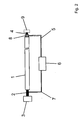
- the Fig. 1 shows a device for calibration of acceleration sensors.
- the device consists of a Hopkinson rod 1, which is formed as a metallic cylindrical rod with a length of 2 m and a diameter of 20 mm.
- a piezoelectric actuator 2 is non-positively connected to the Hopkinson bar 1.
- a cylindrical metallic counterweight 3 with a diameter of 50 mm and a length of 30 mm is glued to the actuator 2.
- the reference sensor 8 is as Laser executed.
- the control or regulating electronics controls the piezoelectric actuator 2 via a control line 7.
- Fig. 2 describes a device for calibrating force sensors.
- the device consists of a Hopkinson rod 1, which is usually formed as a metallic cylindrical rod with a length of 2 m and a diameter of 20 mm.
- a piezoelectric actuator 2 is non-positively connected to the Hopkinson bar 1.
- a cylindrical metallic counterweight 3 has a diameter of 50 mm and a length of 30 mm. It is glued to the piezoelectric actuator 2, so connected cohesively.
- the sensor 4 to be calibrated, the reference sensor 8 and the coupling mass 9 are mounted.
- the control or regulating electronics 6 controls the piezoelectric actuator 2 via a control line 7.
- the signals of the sensor 4 to be calibrated and the reference sensor 8 are fed to a control electronics 6.
- a control electronics 6 By controlling the piezoelectric actuator 2 with defined electrical signals defined waves are generated in the rod. From the reflection of the waves at the right end of the bar, it is thus possible to generate defined acceleration time or force-time signals.
- the signals can be selectively influenced at the right end of the bar.
- the invention thus makes it possible to influence the signal shape (harmonic signals, pulse-shaped signals), the signal amplitude (typically 20 m / s 2 to 100,000 m / s 2 ) as well as the pulse duration (typically 50 ⁇ s to 500 ⁇ s) of the signals.
- the actual signals of the reference sensor can be used to compare these with the desired signal.
- a predistortion of the drive signals for the actuator can be calculated so that the desired signal is generated at the end of the bar.
- calibration signals can be generated which are matched to the respective sensor to be calibrated.
- the continuum properties of the bar can be used.
- the rod can be excited in the longitudinal eigenfrequency with harmonic signals.
- particularly high signal amplitudes can be achieved at the end of the bar with a minimum of installed electrical power.
- the actuator can be controlled periodically with the same signal. If the period of the control is adapted to the duration of the shaft by the rod, the original wave is superimposed with the newly generated wave. By this superimposition can also be achieved particularly high signal amplitudes at the bar end with a low electrical power input.
Abstract
Description
Die Erfindung betrifft ein Verfahren und eine Vorrichtung zur Anregung von Wellen in Stäben zur Kalibrierung von Beschleunigungssensoren und Kraftsensoren, insbesondere mit hohen Amplituden. Ein solcher Sensor ist ein elektromechanischer Wandler, der die mechanische Größe Beschleunigung bzw. Kraft in ein elektrisch messbares Signal, z.B. Ladung oder Spannung wandelt. Um das Übertragungsverhalten des Sensors zu ermitteln, muss eine Kalibrierung durchgeführt werden.The invention relates to a method and a device for excitation of waves in bars for calibration of acceleration sensors and force sensors, in particular with high amplitudes. Such a sensor is an electromechanical transducer which converts the mechanical quantity of acceleration or force into an electrically measurable signal, e.g. Charge or voltage converts. To determine the transmission behavior of the sensor, a calibration must be performed.
Zur Kalibrierung von Beschleunigungssensoren sind verschiedene Einrichtungen bekannt. Vorrichtungen und Verfahren zur Kalibrierung von Schwingungs- und Stoßaufnehmern sind in ISO 16063 beschrieben. Bei der Kalibrierung mit Beschleunigungsamplituden > 1000 m/s2 müssen stoßförmige, das heißt zeitlich begrenzte Signale verwendet werden. Das allgemein bekannte Hammer-Amboss-Prinzip, das auf dem Zusammenstoß zweier Festkörper beruht, arbeitet zufriedenstellend bis zu Beschleunigungsamplituden von 5000 m/s2. Um höhere Beschleunigungen, für hochwertige Kalibrierungen zu erzeugen, muss das Hopkinson-Stab-Prinzip genutzt werden. Das beschriebene Kalibrierverfahren ist in ISO 16063-13 erläutert. Zur Kalibrierung von Kraftsensoren werden üblicherweise statische Verfahren eingesetzt. Das heißt der Sensor wird mit einer statischen Gewichtskraft belastet. Die Kalibrierung von Kraftsensoren mittels zeitlich veränderlicher Signale, die mit einem Hopkinson-Stab erzeugt werden, stellt eine Neuheit dar.Various devices are known for calibrating acceleration sensors. Devices and procedures for vibration and shock absorber calibration are described in ISO 16063. When calibrating with acceleration amplitudes> 1000 m / s 2, it is necessary to use burst-shaped, ie time-limited signals. The well-known hammer-anvil principle, which is based on the collision of two solids, works satisfactorily to acceleration amplitudes of 5000 m / s 2 . In order to produce higher accelerations for high-quality calibrations, the Hopkinson rod principle must be used. The described calibration procedure is explained in ISO 16063-13. For calibration of force sensors usually static methods are used. That is, the sensor is loaded with a static weight. The calibration of force sensors using time-varying signals generated with a Hopkinson rod represents a novelty.
Prinzipiell sind 3 verschiedene Methoden zur Kalibrierung mittels eines Hopkinson-Stabes bekannt. Diese unterschiedlichen Methoden betreffen die verwendete Referenzsensorik.In principle, 3 different methods for calibration by means of a Hopkinson rod are known. These different methods affect the reference sensor used.
Die Beschleunigung am Stabende kann mittels eines optischen Messsystems (z.B. Laservibrometer) oder eines Referenzbeschleunigungssensors bzw. Kraftsensors gemessen werden. Eine weitere Methode zur Kalibrierung ist die Messung der Dehnung des Stabes mittels Dehnungsmessstreifen. Aus der Stabdehnung kann die Beschleunigung des Stabendes berechnet werden.Bar end acceleration may be measured by means of an optical measuring system (e.g., laser vibrometer) or a reference acceleration sensor or force sensor. Another method of calibration is the measurement of the strain of the rod by means of strain gauges. From the bar expansion, the acceleration of the bar end can be calculated.
Das Hopkinson-Stab-Prinzip basiert darauf, dass sich eine mechanische Welle in einem langen schlanken Stab ausbreitet. Durch die Reflektion der Welle an einem freien Stabende entsteht eine Bewegung, welche die für die Kalibrierung der Sensoren geforderte Beschleunigung bzw. Kraft erzeugt. Durch die Eigenschaften eines langen schlanken Stabes können diese Beschleunigungen und Kräfte sehr hohe Amplituden (> 1.000.000 m/s2 bzw. >100.000 N) erreichen.The Hopkinson rod principle is based on a mechanical wave propagating in a long slender rod. By the reflection of the wave at a free rod end creates a movement which generates the required for the calibration of the sensors acceleration or force. Due to the properties of a long slender rod, these accelerations and forces can reach very high amplitudes (> 1,000,000 m / s 2 or> 100,000 N).
Beim klassischen Hopkinson-Stab wird ein Festkörper, z.B. eine Stahlkugel, auf ein Ende des Stabes geschossen, woraus ein mechanischer Kraftstoß resultiert. Durch diesen Kraftstoß wird eine longitudinale Dehnwelle im Stab ausgelöst und kann sich entlang des Stabes fortpflanzen. Der zeitliche Verlauf der Dehnung sowie der Beschleunigungs- und Kraft-Zeit-Verlauf am Stabende ist durch den Kraft-Zeit-Verlauf des Kraftstoßes am Stabanfang definiert. Zum Beispiel regen große Stahlkugeln ein sehr schmales Frequenzspektrum an. Mit kleiner werdendem Kugeldurchmesser werden die Frequenzspektren breiter. Die Maximalamplituden nehmen jedoch mit größer werdendem Kugeldurchmesser stark zu.In the classic Hopkinson rod, a solid, such as a steel ball, is fired at one end of the rod, resulting in a mechanical force surge. This force pulse triggers a longitudinal expansion wave in the rod and can propagate along the rod. The time course of the elongation and the acceleration and force-time curve at the end of the bar is defined by the force-time curve of the momentum at the beginning of the bar. For example, large steel balls stimulate a very narrow frequency spectrum. As the ball diameter becomes smaller, the frequency spectrums become wider. However, the maximum amplitudes increase sharply with increasing ball diameter.
Die Hauptnachteile des klassischen Hopkinson-Stabes sind:
- Die Beschleunigungssignalform ist nicht beeinflussbar.
- Die Impulsdauer der Beschleunigung ist durch die Stoßpartner vorgegeben und kann somit nur aufwändig beeinflusst werden
- Die Reproduzierbarkeit der Beschleunigungssignale und damit das Kalibrierergebnis sind durch den Verschleiß der Stoßpartner eingeschränkt
- eingeschränkter unterer Amplitudenbereich von ca. > 5.000 m/s2.
- The acceleration signal form can not be influenced.
- The pulse duration of the acceleration is given by the collision partners and can therefore only be laboriously influenced
- The reproducibility of the acceleration signals and thus the calibration result are limited by the wear of the impact partners
- limited lower amplitude range of approx.> 5,000 m / s 2 .
In
Ein Testsystem zur Kalibrierung von Beschleunigungssensoren beschreibt
Die Aufgabe der Erfindung besteht in der Entwicklung eines Verfahrens und einer Vorrichtung zur Kalibrierung von Beschleunigungs- und Kraftsensoren mittels eines Hopkinson-Stabes, mit deren Hilfe eine gezielte Beeinflussung der Signalform, der Signalamplitude als auch der Impulsdauer der Signale über einen großen Amplitudenbereich ermöglicht wird. Die Vorrichtung soll einfach aufgebaut sein und sicher und wartungsarm funktionieren.The object of the invention is the development of a method and a device for calibrating acceleration and force sensors by means of a Hopkinson rod, with the aid of a targeted influencing of the waveform, the signal amplitude and the pulse duration of the signals over a wide amplitude range is made possible. The device should be simple and work safely and low maintenance.
Erfindungsgemäß wird die Aufgabe durch die Merkmale des Verfahrensanspruches 1 sowie durch die Merkmale des Vorrichtungsanspruches 3 gelöst. Ausgestaltende Merkmale sind in den abhängigen Ansprüchen 2 und 4 bis 5 beschrieben.According to the invention the object is achieved by the features of
Die erfindungsgemäße Vorrichtung zur Kalibrierung von Beschleunigungs- und Kraftsensoren nutzt eine an einem Hopkinson-Stab in üblicher Weise ausgebildete Referenzsensorik. Die Referenzsensorik kann ein optisches Messsystem (z.B. Laservibrometer) oder ein Referenzsensor sein. Eine weitere Methode zur Kalibrierung ist die Messung der Dehnung des Stabes mittels Dehnungsmessstreifen. Aus der Stabdehnung kann die Beschleunigung bzw. die Kraft des Stabendes berechnet werden.The device according to the invention for calibrating acceleration and force sensors uses a reference sensor system which is designed in a conventional manner on a Hopkinson rod. The reference sensor may be an optical measuring system (e.g., laser vibrometer) or a reference sensor. Another method of calibration is the measurement of the strain of the rod by means of strain gauges. From the bar expansion, the acceleration or the force of the bar end can be calculated.
Ein üblicherweise verwendeter Hopkinson-Stab ist ein etwa 2 m bis 4 m langer, etwa 18 mm bis 30 mm dicker Metallstab.A commonly used Hopkinson rod is a metal rod about 2 to 4 meters long, about 18 to 30 mm thick.
Am Ende des Hopkinson-Stabes ist der zu kalibrierende Sensor befestigt. Zur Erregung eines Beschleunigungs- oder Kraftimpulses dient ein am gegenüberliegenden Ende des Hopkinson-Stabes befestigter elektromechanischer Aktor.At the end of the Hopkinson rod, the sensor to be calibrated is attached. To excite an acceleration or force pulse is a fixed at the opposite end of the Hopkinson rod electromechanical actuator.
Entgegengesetzt zum Hopkinson-Stab ist am elektromechanischen Aktor eine Gegenmasse befestigt, die viel kürzer als die Stablänge sein muss und eine Masse > 1/100 der Stabmasse haben muss. Diese Gegenmasse hat die Funktion 9 die Aktorkraft in den Stab einzuleiten.Opposite to the Hopkinson rod a countermass is attached to the electromechanical actuator, which is much shorter than must be the rod length and a mass must have> 1/100 of the bar mass. This counterweight has the
Der elektromechanische Aktor ist über eine Steuerleitung mit einer Steuer- und Regelelektronik verbunden.The electromechanical actuator is connected via a control line with a control and regulating electronics.
Der elektromechanische Aktor kann vorzugsweise ein piezoelektrischer Aktor oder auch ein magnetostriktiver Aktor sein. Ein magnetostriktiver Aktor lässt sich sehr einfach an den Stab ankoppeln, hat aber einen deutlich schlechteren wirkungsgrad als ein piezoelektrischer Aktor.The electromechanical actuator may preferably be a piezoelectric actuator or a magnetostrictive actuator. A magnetostrictive actuator can be very easily coupled to the rod, but has a significantly lower efficiency than a piezoelectric actuator.
Von der Referenzsensorik kann eine Steuerleitung zur Steuer- und Regelelektronik führen.From the reference sensor, a control line can lead to the control electronics.
Die Vorrichtung kann zur Kalibrierung von Kraft oder Beschleunigungssensoren verwendet werden. Um Beschleunigungssensoren zu kalibrieren, muss der Sensor am freien Stabende montiert werden. Um Kraftsensoren zu kalibrieren, muss der Sensor zuzüglich einer Ankoppelmasse am freien Stabende montiert werden.The device can be used to calibrate force or acceleration sensors. To calibrate accelerometers, the sensor must be mounted at the free end of the bar. To calibrate force sensors, the sensor plus a coupling mass must be mounted on the free end of the rod.
Die Funktionsweise der erfindungsgemäßen Vorrichtung ist wie folgt:The operation of the device according to the invention is as follows:
Die beschriebenen Nachteile von bekannten Kalibrierungsverfahren mittels Hopkinson-Stäben haben die Ursache darin, dass die Welle im Stab durch einen mechanischen Kraftstoß ausgelöst wird. Die vorliegende Erfindung beruht darauf, den mechanischen Kraftstoß durch eine alternative Methode zur Anregung der Wellen im Stab zu ersetzen. Diese Methode soll ein elektrisches Ansteuersignal in einen definierten Kraftstoß wandeln. So geartete Wandler können allgemein als Aktoren bezeichnet werden. Zur Kalibrierung von Beschleunigungs- und Kraftsensoren mittels der erfindungsgemäßen Vorrichtung kommen insbesondere elektromechanische Aktoren zum Einsatz, die einen großen Kraftdynamikbereich (1 mN bis 5 kN) und einen großen nutzbaren Frequenzbereich (> 10 kHz) haben.The described disadvantages of known calibration methods by means of Hopkinson rods are due to the fact that the shaft in the rod is triggered by a mechanical force impulse. The present invention is based on replacing the mechanical force impulse with an alternative method for exciting the waves in the rod. This method is intended to convert an electrical drive signal into a defined force impulse. Such type of transducers can generally be considered Actuators are called. For the calibration of acceleration and force sensors by means of the device according to the invention, in particular electromechanical actuators are used, which have a large range of force dynamics (1 mN to 5 kN) and a large usable frequency range (> 10 kHz).
Eine Regelung der Beschleunigungs- bzw. Kraftimpulsform kann durch Messung der jeweiligen Größe an der Referenzsensorik erfolgen. Die Messgröße wird an eine Regelelektronik übergeben und es kann eine gezielte Vorverzerrung der Ansteuersignale des elektromechanischen Aktors erfolgen.A regulation of the acceleration or force pulse shape can be done by measuring the respective size of the reference sensor. The measured variable is transferred to a control electronics and it can be done a targeted predistortion of the control signals of the electromechanical actuator.
Wenn der Hopkinson-Stab bei seinen Längs-Eigenfrequenzen in den Zustand der Resonanz versetzt wird, erfolgt bei konstanter Erregerleistung eine Maximierung der Beschleunigungs- bzw. Kraftamplitude am Stabende. Dadurch lassen sich besonders energieeffizient große Beschleunigungs- bzw. Kraftamplituden erreichen.When the Hopkinson rod is put into the state of resonance at its longitudinal natural frequencies, with constant exciter power, the acceleration or force amplitude at the rod end is maximized. As a result, it is possible to achieve large acceleration or force amplitudes in a particularly energy-efficient manner.
Durch Überlagerung von Wellen wird die Beschleunigungs- bzw. Kraftamplitude am Ende des Stabes maximiert. Durch wiederholte Energiezufuhr in Form von erneuter Anregung des Hopkinson-Stabes mittels des elektromechanischen Aktors wird die Kraft- bzw. Beschleunigungsamplitude stufenweise erhöht.By superimposing waves, the acceleration or force amplitude at the end of the rod is maximized. Repeated energy supply in the form of renewed excitation of the Hopkinson rod by means of the electromechanical actuator, the force or acceleration amplitude is increased gradually.
Durch die Erfindung können die Nachteile des klassischen Kalibrierungsverfahrens mittels eines Hopkinson-Stabes behoben werden.By the invention, the disadvantages of the classical calibration method can be remedied by means of a Hopkinson rod.
Die Vorteile der Erfindung bestehen darin, dass die Beschleunigungssignalform elektrisch beeinflussbar wird. Auch die Impulsdauer des Beschleunigungssignals ist elektrisch beeinflussbar. Die Erfindung ermöglicht eine Beeinflussung der Signalform (harmonische Signale, impulsförmige Signale), der Signalamplitude (typisch 20 m/s2 bis 100.000 m/s2) als auch der Impulsdauer (typisch 50 us bis 500µs) der Signale.The advantages of the invention are that the acceleration signal shape is electrically influenced. The pulse duration of the acceleration signal is also electrical influenced. The invention makes it possible to influence the signal shape (harmonic signals, pulse-shaped signals), the signal amplitude (typically 20 m / s 2 to 100,000 m / s 2 ) as well as the pulse duration (typically 50 μs to 500 μs) of the signals.
Es entsteht praktisch kein Verschleiß, wodurch die Reproduzierbarkeit der Beschleunigungssignale und des Kalibrierergebnisses verbessert wird.There is virtually no wear, whereby the reproducibility of the acceleration signals and the calibration result is improved.
Weiterhin lassen sich als vorteilhafte Eigenschaften der Kalibriereinrichtung die Möglichkeit der einfachen Automatisierung der Kalibrierabläufe und eine energieeffizientere Arbeitsweise im Vergleich zur herkömmlichen Kalibriereinrichtung nennen.Furthermore, advantageous features of the calibration device include the possibility of simple automation of the calibration sequences and a more energy-efficient mode of operation compared to the conventional calibration device.
Nachfolgend wird die Erfindung an zwei Ausführungsbeispielen näher erläutert. Es zeigen:
- Fig. 1
- Kalibriervorrichtung mit Laservibrometer als Refe- renzsensorik
- Fig. 2
- Kalibriervorrichtung mit Kraftsensor als Referenz- sensorik
- Fig. 1
- Calibration device with laser vibrometer as reference sensor
- Fig. 2
- Calibration device with force sensor as reference sensor
Die
Die Signale des zu kalibrierenden Sensors 4 und der Referenzsensorik 8 werden einer Steuer- bzw. Regelelektronik 6 zugeführt. Durch die Ansteuerung des piezoelektrischen Aktors 2 mit definierten elektrischen Signalen werden in dem Stab definierte Wellen erzeugt. Aus der Reflektion der Wellen am rechten Stabende lassen sich somit definierte Beschleunigungs-Zeit bzw. Kraft-Zeit Signale erzeugen.The signals of the
Durch die Änderung der elektrischen Ansteuersignale am piezoelektrischen Aktor 2 lassen sich die Signale am rechten Stabende gezielt beeinflussen. Die Erfindung ermöglicht so sowohl eine Beeinflussung der Signalform (harmonische Signale, impulsförmige Signale), der Signalamplitude (typisch 20 m/s2 bis 100.000 m/s2) als auch der Impulsdauer (typisch 50 µs bis 500µs) der Signale.By changing the electrical control signals on the
Um ein definiertes Soll-Signal am Stabende zu erzeugen, können die Ist-Signale der Referenzsensorik genutzt werden um diese mit dem Soll-Signal zu vergleichen. Mittels geeigneter mathematischer Methoden kann eine Vorverzerrung der Ansteuersignale für den Aktor berechnet werden, so dass das Soll-Signal am Stabende erzeugt wird. Dadurch lassen sich Kalibriersignale erzeugen, die auf den jeweiligen zu kalibrierenden Sensor abgestimmt sind.In order to generate a defined desired signal at the end of the bar, the actual signals of the reference sensor can be used to compare these with the desired signal. By means of suitable mathematical methods, a predistortion of the drive signals for the actuator can be calculated so that the desired signal is generated at the end of the bar. As a result, calibration signals can be generated which are matched to the respective sensor to be calibrated.
Für die Erzielung von besonders hohen Signalamplituden am rechten Stabende können die Kontinuumseigenschaften des Stabes genutzt werden.To achieve particularly high signal amplitudes at the right end of the bar, the continuum properties of the bar can be used.
Zum einen kann der Stab in der Längs-Eigenfrequenz mit harmonischen Signalen angeregt werden. Dadurch lassen sich besonders hohe Signalamplituden am Stabende mit einem Minimum an eingebrachter elektrischer Leistung erreichen.On the one hand, the rod can be excited in the longitudinal eigenfrequency with harmonic signals. As a result, particularly high signal amplitudes can be achieved at the end of the bar with a minimum of installed electrical power.
Zum anderen kann der Aktor mit dem gleichen Signal periodisch angesteuert werden. Wenn die Periode der Ansteuerung an die Laufzeit der Welle durch den Stab angepasst wird überlagert sich die ursprüngliche Welle mit der jeweils neu erzeugten Welle. Durch diese Überlagerung lassen sich ebenfalls besonders hohe Signalamplituden am Stabende mit einem geringen elektrischen Leistungseintrag erzielen.On the other hand, the actuator can be controlled periodically with the same signal. If the period of the control is adapted to the duration of the shaft by the rod, the original wave is superimposed with the newly generated wave. By this superimposition can also be achieved particularly high signal amplitudes at the bar end with a low electrical power input.
- 11
- StabRod
- 22
- elektromechanischer Aktorelectromechanical actuator
- 33
- Gegenmasseto ground
- 44
- zu kalibrierender Sensorsensor to be calibrated
- 55
- Steuerleitungcontrol line
- 66
- Steuer- bzw. RegelelektronikControl electronics
- 77
- Steuerleitungcontrol line
- 88th
- Referenzsensorikreference sensor
- 99
- AnkoppelmasseAnkoppelmasse
Claims (5)
- Method for calibrating acceleration and force sensors by means of a Hopkinson bar (1), wherein a reference sensor system (8) designed in the normal manner is located on the Hopkinson bar and the sensor to be calibrated (4) is located at one end of the Hopkinson bar, the end of the Hopkinson bar opposite the sensor is excited by means of an electromechanical actuator (2) in order to convert an electrical signal to a mechanical force, the electromechanical actuator can be driven via open-loop control electronics (6), characterized in that the open-loop control electronics also serve as closed-loop control electronics and an acceleration or force pulse form is controlled by- measuring the respective variable by means of the reference sensor system,- transmitting the measurement variable to the open-loop and closed-loop control electronics, and- deliberately predistorting the drive signals for the electromechanical actuator.
- Method according to Claim 1, characterized in that the acceleration or force amplitude at the end of the Hopkinson bar is maximized by superimposition of waves.
- Device for carrying out a method according to Claim 1, wherein a reference sensor system (8), which is designed in the normal manner, is located on a Hopkinson bar (1), and the sensor (4) to be calibrated is located at the end of the Hopkinson bar (1), and in that an electromechanical actuator (2) is mounted fixed to one end of the Hopkinson bar (1), characterized in that the electromechanical actuator (2) is connected via a control line (7) to open-loop and closed-loop control electronics (6), in that- a counterweight (3) is attached to the Hopkinson bar (1) opposite the electromechanical actuator (2), and- in that a control line (5) leads from the reference sensor system (8) to the open-loop and closed-loop control electronics (6).
- Device according to Claim 3, characterized in that the electromechanical actuator (2) is a piezoelectric actuator.
- Device according to Claim 3, characterized in that the electromechanical actuator (2) is a magnetostrictive actuator.
Applications Claiming Priority (2)
| Application Number | Priority Date | Filing Date | Title |
|---|---|---|---|
| DE102008025866A DE102008025866B4 (en) | 2008-05-29 | 2008-05-29 | Method and device for calibrating acceleration and force sensors |
| PCT/DE2009/075023 WO2009143838A1 (en) | 2008-05-29 | 2009-05-18 | Method and device for calibrating acceleration and force sensors |
Publications (3)
| Publication Number | Publication Date |
|---|---|
| EP2158493A1 EP2158493A1 (en) | 2010-03-03 |
| EP2158493B1 true EP2158493B1 (en) | 2011-01-12 |
| EP2158493B9 EP2158493B9 (en) | 2013-05-29 |
Family
ID=41009878
Family Applications (1)
| Application Number | Title | Priority Date | Filing Date |
|---|---|---|---|
| EP09753554.6A Active EP2158493B9 (en) | 2008-05-29 | 2009-05-18 | Method and device for calibrating acceleration and force sensors |
Country Status (11)
| Country | Link |
|---|---|
| US (1) | US9103851B2 (en) |
| EP (1) | EP2158493B9 (en) |
| JP (1) | JP5453617B2 (en) |
| KR (1) | KR101083223B1 (en) |
| CN (1) | CN101918850B (en) |
| AT (1) | ATE495449T1 (en) |
| DE (2) | DE102008025866B4 (en) |
| ES (1) | ES2359489T3 (en) |
| RU (1) | RU2438137C1 (en) |
| TW (1) | TWI410631B (en) |
| WO (1) | WO2009143838A1 (en) |
Families Citing this family (22)
| Publication number | Priority date | Publication date | Assignee | Title |
|---|---|---|---|---|
| CN101968496A (en) * | 2010-06-30 | 2011-02-09 | 中山市嘉科电子有限公司 | Full-automatic correction system for acceleration sensor |
| CN102353813B (en) * | 2011-06-12 | 2012-10-31 | 中北大学 | Broadband high range accelerometer frequency response characteristic calibrating device and method thereof |
| CN102508187B (en) * | 2011-11-30 | 2013-10-23 | 中国西电电气股份有限公司 | Speed parameter calibrating device of high-voltage switch mechanical characteristic tester |
| CN102735398B (en) * | 2012-07-16 | 2014-04-16 | 西北核技术研究所 | Mass block impulse calibration method based on Hopkinson |
| CN103630449B (en) * | 2013-11-11 | 2016-06-08 | 中国人民解放军空军工程大学 | A kind of control method of Hopkinson pressure bar experiment bullet velocity |
| CN104330316A (en) * | 2014-10-28 | 2015-02-04 | 中北大学 | Method for producing extremely-narrow acceleration excitation signal based on pulse laser |
| DE102015013401B3 (en) * | 2015-10-19 | 2017-03-02 | Schenck Process Europe Gmbh | Device and method for calibration and / or adjustment of dynamic force measuring devices |
| CN105259373B (en) * | 2015-10-22 | 2019-01-01 | 中国计量科学研究院 | Steel ball emitter and accelerometer Calibration of Dynamic system comprising the device |
| CN105372051A (en) * | 2015-11-27 | 2016-03-02 | 广东电网有限责任公司电力科学研究院 | Detection device of mechanical characteristics of linear-rotary dual-purpose breaker |
| US11510649B2 (en) * | 2017-04-25 | 2022-11-29 | Michael D. Bernhardt | Methods and apparatuses for prophylactically treating undetected kidney stones using mechanical waves produced from a tactile transducer |
| CN108037315A (en) * | 2017-10-30 | 2018-05-15 | 中国科学院上海微系统与信息技术研究所 | A kind of test device and method of high-impact acceleration meter thermal sensitivity drift |
| CN109238561B (en) * | 2018-09-14 | 2020-05-19 | 上海市计量测试技术研究院 | Method for measuring dynamic sensitivity of force sensor |
| EP3654041B1 (en) | 2018-11-16 | 2022-10-19 | Siemens Industry Software NV | Volume acceleration sensor calibration |
| CN109282941A (en) * | 2018-11-22 | 2019-01-29 | 中国电子科技集团公司第四十九研究所 | A kind of shock measuring system based on monoblock type Hopkinson bar PVDF sensor |
| US11874183B2 (en) | 2019-05-30 | 2024-01-16 | Nextinput, Inc. | Systems and methods for continuous mode force testing |
| CN110187145B (en) * | 2019-06-04 | 2021-06-08 | 西北工业大学 | Device and method for calibrating accelerometer by utilizing wide pulse generated by variable cross-section bullet beam |
| CN111678453B (en) * | 2020-05-18 | 2022-02-18 | 江苏禹治流域管理技术研究院有限公司 | Test method of laser extensometer device for split Hopkinson bar |
| CN111678452B (en) * | 2020-05-18 | 2022-02-18 | 江苏禹治流域管理技术研究院有限公司 | Laser extensometer device for split Hopkinson bar |
| CN112379128B (en) * | 2020-12-08 | 2022-07-05 | 中北大学 | Self-calibration compensation method of resonant micro-mechanical accelerometer based on virtual inertia force |
| CN114295864B (en) * | 2021-12-06 | 2024-01-19 | 中国航空工业集团公司北京长城计量测试技术研究所 | Acceleration excitation device and method for generating variable pulse width amplitude |
| CN115468866B (en) * | 2022-09-22 | 2023-07-28 | 宁波大学 | Test method for Hopkinson one-dimensional dynamic compression force-electricity characteristics of piezoelectric material |
| CN116894210B (en) * | 2023-09-11 | 2023-12-05 | 深圳市力准传感技术有限公司 | Electronic device comprising force sensor and data processing method |
Family Cites Families (14)
| Publication number | Priority date | Publication date | Assignee | Title |
|---|---|---|---|---|
| US3830091A (en) * | 1973-04-05 | 1974-08-20 | Us Navy | Accelerometer comparator |
| US4292835A (en) * | 1980-02-25 | 1981-10-06 | Raymond Engineering, Inc. | Calibration apparatus and method for strain measuring instruments |
| JPS6335944U (en) * | 1986-08-26 | 1988-03-08 | ||
| JPH0652270B2 (en) * | 1989-08-04 | 1994-07-06 | 工業技術院長 | Dynamic Response Characteristic Measurement Method of Impact Accelerometer |
| DE19845185B4 (en) * | 1998-10-01 | 2005-05-04 | Eads Deutschland Gmbh | Sensor with resonant structure and device and method for self-test of such a sensor |
| JP2000260105A (en) | 1999-03-10 | 2000-09-22 | Fujitsu Ltd | Correcting method for acceleration sensor of storage disk device |
| JP4304326B2 (en) * | 2002-03-29 | 2009-07-29 | 独立行政法人産業技術総合研究所 | Method and apparatus for measuring dynamic linearity of acceleration sensor |
| US7101599B2 (en) * | 2002-05-06 | 2006-09-05 | Albany International Corp. | Method to increase bond strength and minimize non-uniformities of woven two-layer multiaxial fabrics and fabric produced according to same |
| US7974150B2 (en) * | 2003-05-16 | 2011-07-05 | Schlumberger Technology Corporation | Methods and apparatus of source control for sequential firing of staggered air gun arrays in borehole seismic |
| JP4257416B2 (en) * | 2003-10-14 | 2009-04-22 | 独立行政法人産業技術総合研究所 | Dynamic sensor sensitivity measurement method and apparatus for force sensor |
| JP4688534B2 (en) | 2005-03-23 | 2011-05-25 | クラリオン株式会社 | Acceleration calibration method and navigation device |
| DE102006031079B4 (en) * | 2006-07-05 | 2010-04-08 | Siemens Ag | Machine tool with a piezoelectric actuator |
| CN1955644A (en) * | 2006-07-07 | 2007-05-02 | 中国航空工业第一集团公司北京长城计量测试技术研究所 | Low frequency angle vibration table |
| JP2008103027A (en) * | 2006-10-19 | 2008-05-01 | Sony Corp | Device and method for cleaning disk, and disk device |
-
2008
- 2008-05-29 DE DE102008025866A patent/DE102008025866B4/en not_active Expired - Fee Related
-
2009
- 2009-05-15 TW TW098116094A patent/TWI410631B/en not_active IP Right Cessation
- 2009-05-18 EP EP09753554.6A patent/EP2158493B9/en active Active
- 2009-05-18 JP JP2010541693A patent/JP5453617B2/en not_active Expired - Fee Related
- 2009-05-18 RU RU2010123663/28A patent/RU2438137C1/en active
- 2009-05-18 ES ES09753554T patent/ES2359489T3/en active Active
- 2009-05-18 CN CN2009801016273A patent/CN101918850B/en not_active Expired - Fee Related
- 2009-05-18 US US12/812,511 patent/US9103851B2/en not_active Expired - Fee Related
- 2009-05-18 AT AT09753554T patent/ATE495449T1/en active
- 2009-05-18 WO PCT/DE2009/075023 patent/WO2009143838A1/en active Application Filing
- 2009-05-18 DE DE502009000286T patent/DE502009000286D1/en active Active
- 2009-05-18 KR KR1020107013453A patent/KR101083223B1/en active IP Right Grant
Also Published As
| Publication number | Publication date |
|---|---|
| JP5453617B2 (en) | 2014-03-26 |
| DE102008025866B4 (en) | 2011-04-14 |
| CN101918850B (en) | 2012-05-30 |
| DE502009000286D1 (en) | 2011-02-24 |
| CN101918850A (en) | 2010-12-15 |
| ATE495449T1 (en) | 2011-01-15 |
| ES2359489T3 (en) | 2011-05-24 |
| EP2158493A1 (en) | 2010-03-03 |
| TW200951439A (en) | 2009-12-16 |
| DE102008025866A1 (en) | 2009-12-31 |
| EP2158493B9 (en) | 2013-05-29 |
| US20100281944A1 (en) | 2010-11-11 |
| RU2438137C1 (en) | 2011-12-27 |
| US9103851B2 (en) | 2015-08-11 |
| TWI410631B (en) | 2013-10-01 |
| WO2009143838A1 (en) | 2009-12-03 |
| KR20100092487A (en) | 2010-08-20 |
| JP2011510268A (en) | 2011-03-31 |
| KR101083223B1 (en) | 2011-11-11 |
Similar Documents
| Publication | Publication Date | Title |
|---|---|---|
| EP2158493B1 (en) | Method and device for calibrating acceleration and force sensors | |
| DE202008007270U1 (en) | Device for calibrating acceleration and force sensors | |
| DE2857924C2 (en) | Device for measuring the density of liquids | |
| EP2265920B1 (en) | Apparatus and method for detecting damage to a machine | |
| DE102010052261A1 (en) | Method and device for calibrating a torque measuring device | |
| DE102007039548B3 (en) | System and method for vibration control | |
| EP2921842B1 (en) | Resonance testing machine | |
| EP3296715B1 (en) | Method for generating data for a rotor blade for a wind turbine | |
| CH683949A5 (en) | Method and apparatus for measuring the dynamic characteristics of a shock-Accelerometers. | |
| DE102014117650B4 (en) | Process for the automated determination of a dynamic stiffness of an object | |
| EP2910914B1 (en) | Weighing device and method for operating the weighing device | |
| DE10333410B4 (en) | Method and device for determining the natural frequencies of a bearing system with a mounted shaft | |
| CN103134583A (en) | Method for testing vibration acceleration of sensor at 100g or above | |
| EP0763732B1 (en) | Device for the acoustic material inspection of molded articles | |
| EP4051995A1 (en) | Test device and method for evaluating the noise behaviour of an assembly | |
| DE2528575B2 (en) | Device for measuring and, if necessary, changing the natural oscillation frequencies of a metallic rod | |
| DE10141518B4 (en) | Device for generating mechanical vibrations in a solid material | |
| DE102014217363B4 (en) | METHOD AND DEVICE ON ROTOR SYSTEMS | |
| AT388053B (en) | ULTRASONIC TESTING DEVICE | |
| DE2556073A1 (en) | Shock absorber test equipment for vehicle suspensions - uses vibrating table to measure damping of component at resonance | |
| DE10318069A1 (en) | Pressure sensor has a resonating beam that is excited at a resonance frequency, which depends on the deformation of a pressure membrane, with the beam subjected to alternate excitation and measurement | |
| WO2012079949A1 (en) | Apparatus for determination of at least one process variable and method for pressure measurement using an apparatus of this type | |
| DE102008003086A1 (en) | Pyro-shock test implementing device for use in e.g. aerospace industry, has plates controlled by generator, where impulse wave is produced on plates by impulse on actuators, and impulse corresponds to characteristics of wave of pyro-shock | |
| DE3832751A1 (en) | METHOD AND MEASURING DEVICE FOR DETERMINING MECHANICAL MEASUREMENTS | |
| DE102009052132A1 (en) | Medical device for treating biological tissue |
Legal Events
| Date | Code | Title | Description |
|---|---|---|---|
| PUAI | Public reference made under article 153(3) epc to a published international application that has entered the european phase |
Free format text: ORIGINAL CODE: 0009012 |
|
| 17P | Request for examination filed |
Effective date: 20091224 |
|
| AK | Designated contracting states |
Kind code of ref document: A1 Designated state(s): AT BE BG CH CY CZ DE DK EE ES FI FR GB GR HR HU IE IS IT LI LT LU LV MC MK MT NL NO PL PT RO SE SI SK TR |
|
| AX | Request for extension of the european patent |
Extension state: AL BA RS |
|
| GRAP | Despatch of communication of intention to grant a patent |
Free format text: ORIGINAL CODE: EPIDOSNIGR1 |
|
| GRAS | Grant fee paid |
Free format text: ORIGINAL CODE: EPIDOSNIGR3 |
|
| GRAA | (expected) grant |
Free format text: ORIGINAL CODE: 0009210 |
|
| AK | Designated contracting states |
Kind code of ref document: B1 Designated state(s): AT BE BG CH CY CZ DE DK EE ES FI FR GB GR HR HU IE IS IT LI LT LU LV MC MK MT NL NO PL PT RO SE SI SK TR |
|
| AX | Request for extension of the european patent |
Extension state: RS |
|
| REG | Reference to a national code |
Ref country code: GB Ref legal event code: FG4D Free format text: NOT ENGLISH |
|
| REG | Reference to a national code |
Ref country code: CH Ref legal event code: EP |
|
| REG | Reference to a national code |
Ref country code: IE Ref legal event code: FG4D Free format text: LANGUAGE OF EP DOCUMENT: GERMAN |
|
| REF | Corresponds to: |
Ref document number: 502009000286 Country of ref document: DE Date of ref document: 20110224 Kind code of ref document: P |
|
| REG | Reference to a national code |
Ref country code: DE Ref legal event code: R096 Ref document number: 502009000286 Country of ref document: DE Effective date: 20110224 |
|
| REG | Reference to a national code |
Ref country code: ES Ref legal event code: FG2A Ref document number: 2359489 Country of ref document: ES Kind code of ref document: T3 Effective date: 20110524 |
|
| REG | Reference to a national code |
Ref country code: NL Ref legal event code: VDEP Effective date: 20110112 |
|
| LTIE | Lt: invalidation of european patent or patent extension |
Effective date: 20110112 |
|
| PG25 | Lapsed in a contracting state [announced via postgrant information from national office to epo] |
Ref country code: HR Free format text: LAPSE BECAUSE OF FAILURE TO SUBMIT A TRANSLATION OF THE DESCRIPTION OR TO PAY THE FEE WITHIN THE PRESCRIBED TIME-LIMIT Effective date: 20110112 Ref country code: IS Free format text: LAPSE BECAUSE OF FAILURE TO SUBMIT A TRANSLATION OF THE DESCRIPTION OR TO PAY THE FEE WITHIN THE PRESCRIBED TIME-LIMIT Effective date: 20110512 Ref country code: GR Free format text: LAPSE BECAUSE OF FAILURE TO SUBMIT A TRANSLATION OF THE DESCRIPTION OR TO PAY THE FEE WITHIN THE PRESCRIBED TIME-LIMIT Effective date: 20110413 Ref country code: PT Free format text: LAPSE BECAUSE OF FAILURE TO SUBMIT A TRANSLATION OF THE DESCRIPTION OR TO PAY THE FEE WITHIN THE PRESCRIBED TIME-LIMIT Effective date: 20110512 Ref country code: NO Free format text: LAPSE BECAUSE OF FAILURE TO SUBMIT A TRANSLATION OF THE DESCRIPTION OR TO PAY THE FEE WITHIN THE PRESCRIBED TIME-LIMIT Effective date: 20110412 Ref country code: LV Free format text: LAPSE BECAUSE OF FAILURE TO SUBMIT A TRANSLATION OF THE DESCRIPTION OR TO PAY THE FEE WITHIN THE PRESCRIBED TIME-LIMIT Effective date: 20110112 Ref country code: SE Free format text: LAPSE BECAUSE OF FAILURE TO SUBMIT A TRANSLATION OF THE DESCRIPTION OR TO PAY THE FEE WITHIN THE PRESCRIBED TIME-LIMIT Effective date: 20110112 Ref country code: LT Free format text: LAPSE BECAUSE OF FAILURE TO SUBMIT A TRANSLATION OF THE DESCRIPTION OR TO PAY THE FEE WITHIN THE PRESCRIBED TIME-LIMIT Effective date: 20110112 |
|
| REG | Reference to a national code |
Ref country code: IE Ref legal event code: FD4D |
|
| PG25 | Lapsed in a contracting state [announced via postgrant information from national office to epo] |
Ref country code: FI Free format text: LAPSE BECAUSE OF FAILURE TO SUBMIT A TRANSLATION OF THE DESCRIPTION OR TO PAY THE FEE WITHIN THE PRESCRIBED TIME-LIMIT Effective date: 20110112 Ref country code: NL Free format text: LAPSE BECAUSE OF FAILURE TO SUBMIT A TRANSLATION OF THE DESCRIPTION OR TO PAY THE FEE WITHIN THE PRESCRIBED TIME-LIMIT Effective date: 20110112 Ref country code: CY Free format text: LAPSE BECAUSE OF FAILURE TO SUBMIT A TRANSLATION OF THE DESCRIPTION OR TO PAY THE FEE WITHIN THE PRESCRIBED TIME-LIMIT Effective date: 20110112 Ref country code: BG Free format text: LAPSE BECAUSE OF FAILURE TO SUBMIT A TRANSLATION OF THE DESCRIPTION OR TO PAY THE FEE WITHIN THE PRESCRIBED TIME-LIMIT Effective date: 20110412 Ref country code: SI Free format text: LAPSE BECAUSE OF FAILURE TO SUBMIT A TRANSLATION OF THE DESCRIPTION OR TO PAY THE FEE WITHIN THE PRESCRIBED TIME-LIMIT Effective date: 20110112 Ref country code: PL Free format text: LAPSE BECAUSE OF FAILURE TO SUBMIT A TRANSLATION OF THE DESCRIPTION OR TO PAY THE FEE WITHIN THE PRESCRIBED TIME-LIMIT Effective date: 20110112 |
|
| PG25 | Lapsed in a contracting state [announced via postgrant information from national office to epo] |
Ref country code: IE Free format text: LAPSE BECAUSE OF FAILURE TO SUBMIT A TRANSLATION OF THE DESCRIPTION OR TO PAY THE FEE WITHIN THE PRESCRIBED TIME-LIMIT Effective date: 20110112 Ref country code: DK Free format text: LAPSE BECAUSE OF FAILURE TO SUBMIT A TRANSLATION OF THE DESCRIPTION OR TO PAY THE FEE WITHIN THE PRESCRIBED TIME-LIMIT Effective date: 20110112 Ref country code: EE Free format text: LAPSE BECAUSE OF FAILURE TO SUBMIT A TRANSLATION OF THE DESCRIPTION OR TO PAY THE FEE WITHIN THE PRESCRIBED TIME-LIMIT Effective date: 20110112 |
|
| PLBE | No opposition filed within time limit |
Free format text: ORIGINAL CODE: 0009261 |
|
| STAA | Information on the status of an ep patent application or granted ep patent |
Free format text: STATUS: NO OPPOSITION FILED WITHIN TIME LIMIT |
|
| BERE | Be: lapsed |
Owner name: SPEKTRA SCHWINGUNGSTECHNIK UND AKUSTIK G.M.B.H. D Effective date: 20110531 |
|
| PG25 | Lapsed in a contracting state [announced via postgrant information from national office to epo] |
Ref country code: RO Free format text: LAPSE BECAUSE OF FAILURE TO SUBMIT A TRANSLATION OF THE DESCRIPTION OR TO PAY THE FEE WITHIN THE PRESCRIBED TIME-LIMIT Effective date: 20110112 Ref country code: CZ Free format text: LAPSE BECAUSE OF FAILURE TO SUBMIT A TRANSLATION OF THE DESCRIPTION OR TO PAY THE FEE WITHIN THE PRESCRIBED TIME-LIMIT Effective date: 20110112 Ref country code: SK Free format text: LAPSE BECAUSE OF FAILURE TO SUBMIT A TRANSLATION OF THE DESCRIPTION OR TO PAY THE FEE WITHIN THE PRESCRIBED TIME-LIMIT Effective date: 20110112 |
|
| 26N | No opposition filed |
Effective date: 20111013 |
|
| PG25 | Lapsed in a contracting state [announced via postgrant information from national office to epo] |
Ref country code: MT Free format text: LAPSE BECAUSE OF FAILURE TO SUBMIT A TRANSLATION OF THE DESCRIPTION OR TO PAY THE FEE WITHIN THE PRESCRIBED TIME-LIMIT Effective date: 20110112 Ref country code: MC Free format text: LAPSE BECAUSE OF NON-PAYMENT OF DUE FEES Effective date: 20110531 |
|
| REG | Reference to a national code |
Ref country code: DE Ref legal event code: R097 Ref document number: 502009000286 Country of ref document: DE Effective date: 20111013 |
|
| PG25 | Lapsed in a contracting state [announced via postgrant information from national office to epo] |
Ref country code: BE Free format text: LAPSE BECAUSE OF NON-PAYMENT OF DUE FEES Effective date: 20110531 |
|
| PG25 | Lapsed in a contracting state [announced via postgrant information from national office to epo] |
Ref country code: MK Free format text: LAPSE BECAUSE OF FAILURE TO SUBMIT A TRANSLATION OF THE DESCRIPTION OR TO PAY THE FEE WITHIN THE PRESCRIBED TIME-LIMIT Effective date: 20110112 |
|
| PG25 | Lapsed in a contracting state [announced via postgrant information from national office to epo] |
Ref country code: LU Free format text: LAPSE BECAUSE OF NON-PAYMENT OF DUE FEES Effective date: 20110518 |
|
| PG25 | Lapsed in a contracting state [announced via postgrant information from national office to epo] |
Ref country code: TR Free format text: LAPSE BECAUSE OF FAILURE TO SUBMIT A TRANSLATION OF THE DESCRIPTION OR TO PAY THE FEE WITHIN THE PRESCRIBED TIME-LIMIT Effective date: 20110112 |
|
| PG25 | Lapsed in a contracting state [announced via postgrant information from national office to epo] |
Ref country code: HU Free format text: LAPSE BECAUSE OF FAILURE TO SUBMIT A TRANSLATION OF THE DESCRIPTION OR TO PAY THE FEE WITHIN THE PRESCRIBED TIME-LIMIT Effective date: 20110112 |
|
| REG | Reference to a national code |
Ref country code: CH Ref legal event code: PL |
|
| PG25 | Lapsed in a contracting state [announced via postgrant information from national office to epo] |
Ref country code: CH Free format text: LAPSE BECAUSE OF NON-PAYMENT OF DUE FEES Effective date: 20130531 Ref country code: LI Free format text: LAPSE BECAUSE OF NON-PAYMENT OF DUE FEES Effective date: 20130531 |
|
| REG | Reference to a national code |
Ref country code: AT Ref legal event code: MM01 Ref document number: 495449 Country of ref document: AT Kind code of ref document: T Effective date: 20140518 |
|
| PG25 | Lapsed in a contracting state [announced via postgrant information from national office to epo] |
Ref country code: AT Free format text: LAPSE BECAUSE OF NON-PAYMENT OF DUE FEES Effective date: 20140518 |
|
| REG | Reference to a national code |
Ref country code: DE Ref legal event code: R082 Ref document number: 502009000286 Country of ref document: DE Representative=s name: LIPPERT STACHOW PATENTANWAELTE RECHTSANWAELTE , DE Ref country code: DE Ref legal event code: R082 Ref document number: 502009000286 Country of ref document: DE Representative=s name: PATENTANWAELTE LIPPERT, STACHOW & PARTNER, DE |
|
| REG | Reference to a national code |
Ref country code: FR Ref legal event code: PLFP Year of fee payment: 8 |
|
| REG | Reference to a national code |
Ref country code: FR Ref legal event code: PLFP Year of fee payment: 9 |
|
| REG | Reference to a national code |
Ref country code: FR Ref legal event code: PLFP Year of fee payment: 10 |
|
| PGFP | Annual fee paid to national office [announced via postgrant information from national office to epo] |
Ref country code: FR Payment date: 20200519 Year of fee payment: 12 Ref country code: DE Payment date: 20200528 Year of fee payment: 12 Ref country code: ES Payment date: 20200618 Year of fee payment: 12 |
|
| PGFP | Annual fee paid to national office [announced via postgrant information from national office to epo] |
Ref country code: GB Payment date: 20200522 Year of fee payment: 12 Ref country code: IT Payment date: 20200528 Year of fee payment: 12 |
|
| REG | Reference to a national code |
Ref country code: DE Ref legal event code: R119 Ref document number: 502009000286 Country of ref document: DE |
|
| GBPC | Gb: european patent ceased through non-payment of renewal fee |
Effective date: 20210518 |
|
| PG25 | Lapsed in a contracting state [announced via postgrant information from national office to epo] |
Ref country code: GB Free format text: LAPSE BECAUSE OF NON-PAYMENT OF DUE FEES Effective date: 20210518 Ref country code: DE Free format text: LAPSE BECAUSE OF NON-PAYMENT OF DUE FEES Effective date: 20211201 |
|
| PG25 | Lapsed in a contracting state [announced via postgrant information from national office to epo] |
Ref country code: FR Free format text: LAPSE BECAUSE OF NON-PAYMENT OF DUE FEES Effective date: 20210531 |
|
| REG | Reference to a national code |
Ref country code: ES Ref legal event code: FD2A Effective date: 20220804 |
|
| PG25 | Lapsed in a contracting state [announced via postgrant information from national office to epo] |
Ref country code: ES Free format text: LAPSE BECAUSE OF NON-PAYMENT OF DUE FEES Effective date: 20210519 |
|
| PG25 | Lapsed in a contracting state [announced via postgrant information from national office to epo] |
Ref country code: IT Free format text: LAPSE BECAUSE OF NON-PAYMENT OF DUE FEES Effective date: 20200518 |