EP2158478B1 - Method and apparatus for the manual non-destructive inspection of tubular axle pins having variable inside and outside radius profiles - Google Patents
Method and apparatus for the manual non-destructive inspection of tubular axle pins having variable inside and outside radius profiles Download PDFInfo
- Publication number
- EP2158478B1 EP2158478B1 EP08826353.8A EP08826353A EP2158478B1 EP 2158478 B1 EP2158478 B1 EP 2158478B1 EP 08826353 A EP08826353 A EP 08826353A EP 2158478 B1 EP2158478 B1 EP 2158478B1
- Authority
- EP
- European Patent Office
- Prior art keywords
- wall
- probe
- analysis
- shaft
- positions
- Prior art date
- Legal status (The legal status is an assumption and is not a legal conclusion. Google has not performed a legal analysis and makes no representation as to the accuracy of the status listed.)
- Active
Links
- 238000000034 method Methods 0.000 title claims description 40
- 238000007689 inspection Methods 0.000 title claims description 12
- 230000001066 destructive effect Effects 0.000 title description 2
- 239000000523 sample Substances 0.000 claims description 152
- 238000004458 analytical method Methods 0.000 claims description 110
- 238000012545 processing Methods 0.000 claims description 30
- 238000002604 ultrasonography Methods 0.000 claims description 29
- 238000001514 detection method Methods 0.000 claims description 20
- 238000005211 surface analysis Methods 0.000 claims description 19
- 230000007547 defect Effects 0.000 claims description 18
- 238000006073 displacement reaction Methods 0.000 claims description 15
- 239000006249 magnetic particle Substances 0.000 claims description 6
- 230000004907 flux Effects 0.000 claims description 5
- GNFTZDOKVXKIBK-UHFFFAOYSA-N 3-(2-methoxyethoxy)benzohydrazide Chemical compound COCCOC1=CC=CC(C(=O)NN)=C1 GNFTZDOKVXKIBK-UHFFFAOYSA-N 0.000 claims description 2
- FGUUSXIOTUKUDN-IBGZPJMESA-N C1(=CC=CC=C1)N1C2=C(NC([C@H](C1)NC=1OC(=NN=1)C1=CC=CC=C1)=O)C=CC=C2 Chemical compound C1(=CC=CC=C1)N1C2=C(NC([C@H](C1)NC=1OC(=NN=1)C1=CC=CC=C1)=O)C=CC=C2 FGUUSXIOTUKUDN-IBGZPJMESA-N 0.000 claims description 2
- 238000002592 echocardiography Methods 0.000 claims 15
- 230000001747 exhibiting effect Effects 0.000 claims 2
- 230000001154 acute effect Effects 0.000 description 8
- 238000010234 longitudinal analysis Methods 0.000 description 7
- 230000007847 structural defect Effects 0.000 description 7
- 239000000463 material Substances 0.000 description 6
- 230000015654 memory Effects 0.000 description 6
- 239000007787 solid Substances 0.000 description 6
- 240000008042 Zea mays Species 0.000 description 4
- 238000009659 non-destructive testing Methods 0.000 description 4
- 230000005540 biological transmission Effects 0.000 description 3
- 238000012423 maintenance Methods 0.000 description 3
- 230000000007 visual effect Effects 0.000 description 3
- PEDCQBHIVMGVHV-UHFFFAOYSA-N Glycerine Chemical compound OCC(O)CO PEDCQBHIVMGVHV-UHFFFAOYSA-N 0.000 description 2
- 230000005284 excitation Effects 0.000 description 2
- 238000005242 forging Methods 0.000 description 2
- 239000007788 liquid Substances 0.000 description 2
- 230000033001 locomotion Effects 0.000 description 2
- 238000003754 machining Methods 0.000 description 2
- 238000004519 manufacturing process Methods 0.000 description 2
- 239000002245 particle Substances 0.000 description 2
- 239000002964 rayon Substances 0.000 description 2
- 239000008186 active pharmaceutical agent Substances 0.000 description 1
- 238000010835 comparative analysis Methods 0.000 description 1
- 230000000295 complement effect Effects 0.000 description 1
- 230000009850 completed effect Effects 0.000 description 1
- 239000002131 composite material Substances 0.000 description 1
- 230000008878 coupling Effects 0.000 description 1
- 238000010168 coupling process Methods 0.000 description 1
- 238000005859 coupling reaction Methods 0.000 description 1
- 230000007423 decrease Effects 0.000 description 1
- 230000001419 dependent effect Effects 0.000 description 1
- 229940082150 encore Drugs 0.000 description 1
- 238000005265 energy consumption Methods 0.000 description 1
- 210000001508 eye Anatomy 0.000 description 1
- 238000005206 flow analysis Methods 0.000 description 1
- 235000011187 glycerol Nutrition 0.000 description 1
- 238000007654 immersion Methods 0.000 description 1
- 230000000670 limiting effect Effects 0.000 description 1
- 230000005291 magnetic effect Effects 0.000 description 1
- 230000000737 periodic effect Effects 0.000 description 1
- 238000011084 recovery Methods 0.000 description 1
- 230000009467 reduction Effects 0.000 description 1
- 230000002829 reductive effect Effects 0.000 description 1
- 239000011343 solid material Substances 0.000 description 1
- XLYOFNOQVPJJNP-UHFFFAOYSA-N water Substances O XLYOFNOQVPJJNP-UHFFFAOYSA-N 0.000 description 1
- 229910001868 water Inorganic materials 0.000 description 1
Images

Classifications
-
- G—PHYSICS
- G01—MEASURING; TESTING
- G01N—INVESTIGATING OR ANALYSING MATERIALS BY DETERMINING THEIR CHEMICAL OR PHYSICAL PROPERTIES
- G01N29/00—Investigating or analysing materials by the use of ultrasonic, sonic or infrasonic waves; Visualisation of the interior of objects by transmitting ultrasonic or sonic waves through the object
- G01N29/22—Details, e.g. general constructional or apparatus details
- G01N29/26—Arrangements for orientation or scanning by relative movement of the head and the sensor
- G01N29/262—Arrangements for orientation or scanning by relative movement of the head and the sensor by electronic orientation or focusing, e.g. with phased arrays
-
- G—PHYSICS
- G01—MEASURING; TESTING
- G01N—INVESTIGATING OR ANALYSING MATERIALS BY DETERMINING THEIR CHEMICAL OR PHYSICAL PROPERTIES
- G01N29/00—Investigating or analysing materials by the use of ultrasonic, sonic or infrasonic waves; Visualisation of the interior of objects by transmitting ultrasonic or sonic waves through the object
- G01N29/04—Analysing solids
- G01N29/06—Visualisation of the interior, e.g. acoustic microscopy
- G01N29/0609—Display arrangements, e.g. colour displays
-
- G—PHYSICS
- G01—MEASURING; TESTING
- G01N—INVESTIGATING OR ANALYSING MATERIALS BY DETERMINING THEIR CHEMICAL OR PHYSICAL PROPERTIES
- G01N29/00—Investigating or analysing materials by the use of ultrasonic, sonic or infrasonic waves; Visualisation of the interior of objects by transmitting ultrasonic or sonic waves through the object
- G01N29/22—Details, e.g. general constructional or apparatus details
- G01N29/225—Supports, positioning or alignment in moving situation
-
- G—PHYSICS
- G01—MEASURING; TESTING
- G01N—INVESTIGATING OR ANALYSING MATERIALS BY DETERMINING THEIR CHEMICAL OR PHYSICAL PROPERTIES
- G01N29/00—Investigating or analysing materials by the use of ultrasonic, sonic or infrasonic waves; Visualisation of the interior of objects by transmitting ultrasonic or sonic waves through the object
- G01N29/22—Details, e.g. general constructional or apparatus details
- G01N29/26—Arrangements for orientation or scanning by relative movement of the head and the sensor
- G01N29/265—Arrangements for orientation or scanning by relative movement of the head and the sensor by moving the sensor relative to a stationary material
-
- G—PHYSICS
- G01—MEASURING; TESTING
- G01N—INVESTIGATING OR ANALYSING MATERIALS BY DETERMINING THEIR CHEMICAL OR PHYSICAL PROPERTIES
- G01N29/00—Investigating or analysing materials by the use of ultrasonic, sonic or infrasonic waves; Visualisation of the interior of objects by transmitting ultrasonic or sonic waves through the object
- G01N29/22—Details, e.g. general constructional or apparatus details
- G01N29/26—Arrangements for orientation or scanning by relative movement of the head and the sensor
- G01N29/27—Arrangements for orientation or scanning by relative movement of the head and the sensor by moving the material relative to a stationary sensor
-
- G—PHYSICS
- G01—MEASURING; TESTING
- G01N—INVESTIGATING OR ANALYSING MATERIALS BY DETERMINING THEIR CHEMICAL OR PHYSICAL PROPERTIES
- G01N2291/00—Indexing codes associated with group G01N29/00
- G01N2291/04—Wave modes and trajectories
- G01N2291/044—Internal reflections (echoes), e.g. on walls or defects
-
- G—PHYSICS
- G01—MEASURING; TESTING
- G01N—INVESTIGATING OR ANALYSING MATERIALS BY DETERMINING THEIR CHEMICAL OR PHYSICAL PROPERTIES
- G01N2291/00—Indexing codes associated with group G01N29/00
- G01N2291/10—Number of transducers
- G01N2291/106—Number of transducers one or more transducer arrays
-
- G—PHYSICS
- G01—MEASURING; TESTING
- G01N—INVESTIGATING OR ANALYSING MATERIALS BY DETERMINING THEIR CHEMICAL OR PHYSICAL PROPERTIES
- G01N2291/00—Indexing codes associated with group G01N29/00
- G01N2291/26—Scanned objects
- G01N2291/263—Surfaces
- G01N2291/2634—Surfaces cylindrical from outside
-
- G—PHYSICS
- G01—MEASURING; TESTING
- G01N—INVESTIGATING OR ANALYSING MATERIALS BY DETERMINING THEIR CHEMICAL OR PHYSICAL PROPERTIES
- G01N2291/00—Indexing codes associated with group G01N29/00
- G01N2291/26—Scanned objects
- G01N2291/263—Surfaces
- G01N2291/2636—Surfaces cylindrical from inside
Definitions
- axle axles As known to those skilled in the art, some axle axles, and especially those that must withstand heavy loads, must be subjected to non-destructive testing at different stages of manufacture and maintenance to meet standards. International.
- the known non-destructive testing methods are quite well adapted to solid (or massive) axle axles. They are generally based on an acoustic analysis, using ultrasound probes, cf US A 3,685,350 and FR A 1,350,320 as well as possibly on a complementary analysis, as for example a surface analysis cf WO 2006/099397 or radiographic analysis.
- echo indication here means information obtained in a wall by reflection on an interface (material / air) or on an imperfection or on a defect (structural). Furthermore, here is meant by “imperfection” a portion of a wall that has induced an echo whose amplitude is below a chosen threshold, and therefore that is not likely to lead to the scrapping of the axis. Finally, here “defect” is understood to mean a part of a wall which has induced an echo whose amplitude is greater than the chosen threshold, and therefore which is likely to lead to the scrapping of the axis.
- steps a) to c) must be done in this order, but that the other steps mentioned d) to i) are not necessarily in this order. In particular, a step i) can quite occur after a step c).
- tubular axes to be controlled are intended to be part of the axles of freight wagons (s) or passengers. But, the invention is not limited to this application. It concerns indeed any type of hollow (tubular) revolution product, subjected to stresses in service, such as for example fatigue forces, and whose wall comprises known and variable external and internal ray profiles.
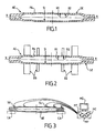
- a tubular (axle) axle AE comprises a wall PA which is defined by means of hot forging and machining operations and which ultimately has variable outer radius R1 and inner R2 profiles.
- the radial thickness (that is to say in a direction perpendicular to the longitudinal axis XX) is not necessarily constant.
- the profiles of the outer radii R1 and inner R2 are not necessarily superimposable to a near homothety.
- Such an apparatus comprises at least one ultrasound probe SU (here five are shown), a control module MC and a processing module MT, and preferably an EC screen.
- the control module MC, the processing module MT and the screen EC can be part of a microcomputer (or a workstation) MO connected to the probes SU, as illustrated by way of non-limiting example on the figure 3 .
- the apparatus comprises at least two SU probes.
- axle AE to be tested When the axle AE to be tested is not mounted on a wagon (as shown in figure 3 ), it can for example be deposited on CA shims (or any support means adapted for this purpose), with or without its equipment (s).
- the ultrasound probes SU may be either arranged to emit ultrasound in a single direction whose angle is chosen but may vary depending on the needs, either of the type called phase-array (or "phased array"), c that is, arranged to emit ultrasound in a plurality of directions within an angular sector chosen according to the needs (by virtue of an electronic angular scanning). It is also possible to obtain the equivalent of a longitudinal displacement of the sensor by means of an electronic scanning.
- phase-array or "phased array”
- each probe SU comprises a single detection element responsible for receiving the echoes from the wall PA object of the analysis.
- each probe SU comprises several detection elements responsible for receiving the echoes from the wall PA object of the analysis after refraction and / or reflections (possibly multiple) from different angles.
- the detection elements are generally made of a composite material and placed on transducers. When the sensing elements of a probe are excited, they produce a divergent analysis beam. The shape of the latter and therefore its general direction of incidence can be modified electronically by introducing time delays at the moments of excitation of selected detection elements of a probe.
- a phase array probe can thus constitute several (for example several tens) virtual probes according to the combinations of which it is the subject.
- the excitation frequency of the transducers is typically of the order of a few megahertz (2 to 5 MHz). When they are not excited in emission, these same detection elements are used to detect echoes from material / air or material / liquid interfaces, imperfections and defects. They thus constitute transmitter / receiver type sensors.
- the internal R2 and external R1 radii profiles presented by the wall PA and any congestion and environment of the axis AE are analyzed, for example by means of a simulation software of CIVA 8.0 type (developed and marketed by the Office of the Atomic Energy (CEA)), in order to determine the number of SU probes that will be necessary to analyze all or only a selected part of the AE axis, given their type (monodirectional or phase network). (and in this second case their number of sensing elements)) and that they can be oriented to perform longitudinal or transverse analyzes in first and second opposite directions.
- CIVA 8.0 type developed and marketed by the Office of the Atomic Energy (CEA)
- Longitudinal analysis is here understood to mean an analysis carried out with a view to looking for defects and / or imperfections oriented preferentially longitudinally or at a low acute angle with respect to the longitudinal direction XX (acute angle typically less than ⁇ 25 °), and of preferably less than ⁇ 5 °).
- the term obliquity is sometimes used to designate this orientation of the defect.
- This analysis is carried out by means of a beam emitted in a direction perpendicular to the longitudinal direction XX, that is to say whose general direction is substantially contained in a plane perpendicular to the longitudinal direction XX or which makes a weak acute angle (typically less than ⁇ 10 °) with this perpendicular direction.
- cross-analysis is understood to mean an analysis carried out with a view to looking for defects and / or imperfections oriented preferentially transversely or at a small acute angle with respect to a plane perpendicular to the longitudinal direction XX (typically lower acute angle). at ⁇ 25 °, and preferably below ⁇ 5 °).
- the term obliquity is sometimes used to designate this orientation of the defect.
- This analysis is performed by means of a beam emitted in a direction parallel to the longitudinal direction XX, that is to say whose general direction is substantially contained in a plane which itself contains the longitudinal direction XX or which makes a low acute angle (typically less than ⁇ 10 °) with this longitudinal direction.
- the term "environment of the axis” here means the content of the space that surrounds it when it must be controlled. It will be understood that when controlling an axis AE which is mounted on a wagon, itself placed on rails, the portions that can be controlled can be significantly reduced.
- the emission angle of a monodirectional SU probe must generally be able to vary between 0 ° and about 70 ° with respect to the longitudinal direction XX, and the angular sector of emission of a phase array probe SU must generally be between about 0 ° and about 70 ° with respect to the longitudinal direction XX.
- the control module MC has determined for each probe SU the (first) chosen place where it will have to be initially and manually placed relative to the axis AE so as to analyze a first selected portion of the wall PA in a first selected angular sector, oriented in a first longitudinal or transverse direction, as well as the possible (second) chosen location where it will have to be later and manually placed relative to the axis AE so as to analyze a second selected portion of the wall PA in a second selected angular sector, oriented in a second longitudinal or transverse direction opposite to the first direction, the SU probes can be placed manually at their respective first selected locations.
- This manual placement of the probes SU relative to the axis AE can be done at first selected locations which are located either on the outer surface SE of the wall PA, or on the internal surface SI of this wall PA, as required (and the configuration of the AE axis). For example, it is possible to start by performing ultrasound analyzes by placing SU probes on the outer surface SE of the wall PA, and then possibly completing these analyzes by then placing probes SU on the internal surface SI of the PA wall (that is to say inside the tubular axis AE). But the opposite is also possible.
- the coupling between the probes SU and the internal surface SI or external SE of a wall PA can be done by any means known to those skilled in the art, and in particular by means of glycerine or by immersion in water of preferably mixed with an anticorrosive product.
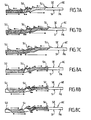
- Figures 4A and 4B two examples of placement of a probe SU in two selected locations of the outer surface SE of a portion of a wall PA of axis AE, for a longitudinal analysis.
- FIG 5 an example of placement of a probe SU at a chosen location of the outer surface SE of a part of a wall PA of axis AE, for a transverse analysis.
- FIG 6 an example of placement of a probe SU at a selected location of the inner surface SI of a part of a wall PA of axis AE, for a longitudinal analysis.
- an SU probe can analyze a portion that has been assigned to it either by being held at a selected location or by being manually moved by a technician, longitudinally and / or transversely, between a position of departure (corresponding to the location initially chosen) and an end position (corresponding to another chosen location), possibly via one or more intermediate positions (each corresponding to another chosen location).
- the control module MC is responsible for determining, according to the internal and external profiles of the AE axis to be controlled and any congestion and environment of the latter, at least first and second locations chosen on the external surface SE or internal SI of the wall PA where the probes SU are to be placed manually so that they analyze selected first and second portions of the wall PA respectively in selected first and second angular sectors, oriented along first and second longitudinal directions (direction XX) or crosswise (direction perpendicular to the direction XX) opposite, and they thus acquire analysis data for different relative angular positions of the axis AE with respect to the probes SU.
- the solution used to analyze an entire wall portion PA chosen depends on the type of probe SU available and, in the case of phase-array probes, on the number of detection elements that constitute them. Indeed, it will be understood that if the number of detection elements of a probe SU is adapted to the coverage of the wall portion PA which has been allocated to it, it is unnecessary to provide a manual longitudinal movement because it can be substituted an electronic scan.
- a probe SU must cover a wall portion PA of longitudinal extension equal to 100 mm, then it must comprise at least 200 detection elements of 0.5 mm side, for example separated two by two a distance of about 0.1 mm. It is recalled that the smaller the dimensions of the detection elements, the larger the angular areas of analysis can be. A compromise can be found between the number of detection elements of the SU probes and the coverage extension possibilities offered by the electronic scanning, so as to avoid manual longitudinal movements.
- each of these probes SU performs the analysis of the first portion of the wall PA, which has been determined for it by the control module MC, in a first selected angular sector which is oriented in a first longitudinal or transverse direction .
- Each probe SU can thus acquire analysis data for the current relative angular position of the axis AE with respect to said probe SU.
- each probe SU can carry out a new acquisition of analysis data after each angular displacement.
- analysis data relating to the entire circumference of each first portion of PA wall inspected may be available.
- This analysis data includes, for example, the transmission angles, the transmission and reception times of the ultrasound (or what is equivalent the time intervals between the transmission and reception instants), and the reception angles.
- they are transmitted by the probes SU to the control module MC, which is responsible for storing them in a memory MY in correspondence of the longitudinal and angular positions of the first portions inspected with respect to a chosen reference frame, as well as possibly of the identifier of the SU probe used to obtain them.
- the probes SU are manually replaced on the external surface SE or internal SI of the wall PA in second places (chosen according to its profiles and any congestion and environment of the axis AE) so that they proceed to the analysis of the second portions of the wall PA which have respectively been assigned to them, in second selected angular sectors which are oriented in a second longitudinal or transverse direction, opposite to the first direction.
- the second direction corresponds to a direction going from the right to the left of said longitudinal axis XX.
- first direction corresponds to a direction from the left to the right of a second axis perpendicular to the longitudinal axis XX
- second direction corresponds to a direction going from the right to the left of said second axis.
- Each probe SU replaced manually can thus acquire analysis data for its current angular position with respect to the axis AE.
- each probe SU can carry out a new acquisition of analysis data after each angular displacement. It is thus possible to have analysis data relating to the entire circumference of each second portion of PA wall inspected.
- These analysis data are, for example, transmitted by the probes SU to the control module MC, which is responsible for storing them in a memory corresponding to the longitudinal and angular positions of the second portions inspected with respect to a chosen reference frame, as well as possibly of the identifier of the SU probe used to obtain them.
- the emission angle of a monodirectional SU probe must generally be able to vary between 0 ° and about 70 ° relative to the longitudinal direction XX or transverse, and the angular sector of emission of a phase array probe SU must generally be between about 0 ° and about 70 ° with respect to the longitudinal direction XX or transverse.
- each two-way arrow represents the longitudinal extension of the (first) portion analyzed by a SU probe (placed above).
- the size and / or the environment of an axle axis AE reduces (sen) noticeably, in some of its parts, the longitudinal extensions of the portions that can be technically analyzed (covered) by the same probe SU. This is particularly the case in the parts which are located under the wheels, which have a greater probability of having structural defects induced by the press fitting and / or the supported loads, and therefore must be subjected to an inspection (analysis) as precise as possible and as complete as possible.
- the stored analysis data are extracted by the processing module MT, which is then responsible for grouping them according to the axis zones that they concern so as to constitute maps that represent the transverse or longitudinal orientations and the positions of echo indications within the PA wall.
- the echo indications result from a reflection on either a material / air or material / liquid interface, or on an imperfection, or on a defect.
- the longitudinal analyzes are more particularly adapted to the detection of imperfections and transverse defects (which are generally the most frequent), while the transverse analyzes are more particularly adapted to the detection of imperfections and longitudinal defects .
- processing module MT may optionally be arranged in such a way as to make “correlations” between analysis data relating to identical zones constituting the zones of overlap of first (s) and / or second (s) wall portions. . They can thus constitute “raw” maps of these areas of recovery, possibly of three-dimensional type (3D).
- the data files constituting the raw cards are preferably stored in a memory MY. These cards can then either be displayed individually (one after the other) or grouped (several at the same time) on the EC screen for analysis by a technician, or first analyzed in an automated way and then converted into "corrected” or "fault” cards that can be displayed on the EC screen individually or in a grouped manner.
- the processing module MT may be responsible for comparing the data of at least some of the cards, which have been obtained on an AE axis to be checked, with data of first standard cards which have been obtained on a first standard axis of the same type as the one checked, but without defects.
- the processing module MT retains only the data that is representative of echo indications that are not present in the first standard cards, in order to constitute corrected cards that it stores in the memory MY.
- the processing module MT may be responsible for comparing the data of at least some of the cards (raw or corrected) that have been obtained on an axis AE with data of second standard cards which have been obtained on a second standard axis of the same type as the one checked, but with known defects. In this case, the processing module MT retains only the data which are representative of indications of echoes representative of known defects present in the second standard cards, in order to constitute fault cards which it stores in the memory MY.
- the processing module MT may be responsible for comparing, with a selected threshold amplitude, the amplitudes of the echo indications represented on at least some of the cards. In this case, the processing module MT retains only those data which are representative of echo indications whose amplitudes are greater than the chosen threshold amplitude and which are therefore supposed to be derived from defects, in order to constitute fault cards.
- the processing module MT generates an alarm (sound and / or visual (displayed on the screen EC)) each time it detects that an amplitude is greater than the chosen threshold amplitude.
- a PA wall can be analyzed by manually placing the probes SU on its outer surface SE or on its inner surface SI. But we can also consider performing a double analysis, for example by manually starting the SU probes on its outer surface SE and then manually placing some of the SU probes on its internal surface SI. More precisely, in this case, the probes SU are manually placed on the outer surface SE of the wall PA at the first selected locations and, with these probes SU, the first selected portions of the wall PA are analyzed in first selected angular sectors oriented next a first longitudinal direction (or transverse), in order to acquire analysis data for different angular positions of the probes SU with respect to the axis AE.
- the probes SU are manually replaced on the outer surface SE of the wall PA at the second selected locations and, with these probes SU, the selected second portions of the wall PA are analyzed in second selected angular sectors, oriented along a second longitudinal direction (or transverse), opposite to the first, in order to acquire analysis data for different angular positions of the probes SU with respect to the axis AE.
- the probes SU are manually placed on the inner surface SI of the wall PA at the third selected locations and, with these probes SU, the selected third portions of the wall PA are analyzed in selected third angular sectors, oriented according to FIG. least one longitudinal direction (or transverse), or even two opposite directions, in order to acquire analysis data for different angular positions of the probes SU with respect to the axis AE.
- the processing module MT then constitutes, from the set of analysis data, representative maps of the positions and orientations of the echo indications within the wall PA.
- This double analysis from the outside and the inside can cover all of the portions of an AP wall to be inspected, whereas this may be impossible by means of the only analysis by the outside, because of the profiles of this wall PA and / or congestion and / or the environment of the axis AE.
- first longitudinal analysis in both directions (as indicated above) and from outside (or inside), then a second transverse analysis in at least one direction and from the outside ( or from the inside), in order to constitute representative maps of the transverse orientations and echo indication positions within the PA wall and representative maps of the longitudinal orientations and the echo indication positions within the same PA wall.
- the internal analyzes may in certain cases require a reaming of at least the ends of the tubular axle axis AE, so as to allow the placement of at least one probe SU within this axis AE, against the inner surface SI of its wall PA, as well as its possible manual movement.
- the locations of placement of the probes SU, the different angles or different angular sectors of ultrasonic analysis of each of the probes SU and the wall portions allocated to the different probes may be determined by the control module MC depending of constraint (s).
- part of a control is made with a beam whose general direction is substantially contained in a plane which itself contains the longitudinal direction XX and on wall portions having two to two chosen covering, for example 50%, and / or that part of a control is made with successive beams whose general directions are substantially contained in planes which make acute angles with this longitudinal direction XX which grow between 0 ° and + 20 ° and between 0 ° and -20 °.
- the angle of inclination of the elements of Detection of an SU sensor can be chosen as needed.
- an angle of 45 ° with respect to the longitudinal direction XX may be chosen.
- each transducer must be adjusted during a calibration phase, for example so that the amplitude of the signal obtained on the first echo from an interface of the wall PA corresponds to an amplitude equal for example to about 50% of the total amplitude dynamic used for the cards.
- the calibration phase also preferably comprises a first part dedicated to obtaining the aforementioned standard maps, which are representative of the results of ultrasonic analyzes carried out on a standard tubular axle axis of the same type as those to be made. subject to control, but sound (ie, free from imperfections and structural defects).
- This first part of the calibration phase makes it possible to know in advance the echoes which are induced by the geometry of the wall PA (and in particular the corners and more generally the areas in which the inner radius R2 or outer radius R1 varies from important way) and thus to differentiate them from those induced by the imperfections and structural defects in the tubular axles AE AE to control.
- the calibration phase may also include a second part dedicated to obtaining the aforementioned standard cards, which are representative of the results of ultrasonic analyzes performed on a standard tubular axle axis of the same type as those to be made. subject to control, but which standard includes characteristic structural or artificial defects (such as notches or characteristic cavities) defined in selected locations. These characteristic structural or artificial defects are defined according to specifications and / or standards that set a sorting threshold between imperfections and defects. When the amplitude of the signal coming from the echoes on natural defects is lower than the sorting threshold, there is an imperfection. In the opposite case (above the threshold) there is a defect.
- This second part of the calibration phase makes it possible to know in advance the echoes that are induced by characteristic structural or artificial defects and thus to be able to easily detect in the cards, compared to a sorting threshold, the "objects" that induce echoes (or signatures) of similar types in the tubular axles AE to be controlled.
- an analysis of the outer surface SE of the wall PA can be performed to acquire surface analysis data for different relative positions of the axis AE with respect to the surface analysis means.
- the so-called leakage flux and the so-called eddy current are advantageous in that they provide surface analysis data from which maps representative of the positions and orientations of surface defects of the wall PA can be made.
- the data files constituting these surface fault maps are preferably stored in a memory MY so that said surface fault maps can be displayed individually (one after the other) or in a grouped manner (several at the same time) , possibly with structural fault maps (obtained by ultrasound), on the EC screen for analysis by a technician and / or confrontation with the maps obtained with the SU probes. This can also allow an automatic comparison by the device of surface fault maps and ultrasonic maps.
- MPI Magnetic Particle Inspection
- this technique consists in covering the outer surface SE with a PA wall PA wall by means of magnetic particles and a developer, then magnetizing the wall to be inspected and then observing (with the eyes) visually under UV light (ultraviolet) the orientation irregularities of these magnetic particles, orientation irregularities related to the presence of defects or imperfections.
- UV light ultraviolet light
- cards discussed above can be of any type known to those skilled in the art, including type A-Scan, B-Scan, C-Scan, D-Scan, S -Scan (or Sector Scan).
- type A-Scan type A-Scan
- B-Scan C-Scan
- D-Scan S -Scan (or Sector Scan).
- S-Scan type cards which provide location indications in the volume - a map for each position of a probe.
- imperfections and defects of about 2 mm thickness ie about 5% of the nominal thickness of the wall PA in the radial direction
- longitudinal or transverse cavities (or "flaws") with disorientation angles (or “tilt angles”) of up to about 60 ° can be detected.
- the invention is not limited to the exemplary methods and apparatus for controlling tubular axles axles described above, only by way of example, but it encompasses all the variants that may be considered by the man of the art within the scope of the claims below.
Description
L'invention concerne les axes d'essieu, qui sont par exemple utilisés dans le domaine ferroviaire, et plus précisément le contrôle (ou l'inspection) de tels axes au moyen de technique(s) non destructive(s).The invention relates to axle axles, which are for example used in the railway field, and more precisely the control (or inspection) of such axes by means of non-destructive technique (s).
Comme le sait l'homme de l'art, certains axes d'essieu, et notamment ceux qui doivent supporter des charges importantes, doivent faire l'objet de contrôles non destructifs à différents stades de fabrication et de maintenance afin de répondre à des standards internationaux. Les procédés de contrôle non destructif connus sont assez bien adaptés aux axes d'essieu pleins (ou massifs). Ils reposent généralement sur une analyse acoustique, au moyen de sondes à ultrasons, cf
A partir des données d'analyse acquises, on peut estimer les positions des imperfections et des défauts transversaux ou longitudinaux au sein du matériau plein qui constituent un axe et ainsi déterminer si cet axe satisfait ou non à un standard international (de fabrication ou de maintenance périodique).From the acquired analysis data, it is possible to estimate the positions of imperfections and transverse or longitudinal defects within the solid material which constitute an axis and thus to determine whether this axis meets an international standard (of manufacture or of maintenance) or not. periodic).
Il a été récemment proposé de remplacer certains axes d'essieu pleins (ou massifs) par des axes d'essieu tabulaires dont la paroi présente des profils de rayons extérieur et intérieur variables. Ces nouveaux axes tubulaires sont particulièrement avantageux car ils permettent une réduction notable de poids, typiquement de l'ordre de 30%, et donc une augmentation de la charge transportée, accompagnée d'une diminution de la consommation d'énergie et donc de la pollution. Mais, le contrôle de ce type d'axe tubulaire pose un certain nombre de problèmes.It has recently been proposed to replace certain solid axles (or solid axles) with tabular axle axles whose walls have variable outer and inner radius profiles. These new tubular axes are particularly advantageous because they allow a significant reduction in weight, typically of the order of 30%, and therefore an increase in the load transported, accompanied by a decrease in the energy consumption and therefore pollution. But, the control of this type of tubular axis poses a certain number of problems.
En effet, en raison de l'existence d'un profil de rayon intérieur variable, il est difficile de différencier les échos résultant de zones anguleuses (ou coins) de ceux résultant d'imperfections ou de défauts structurels.Indeed, because of the existence of a variable inner radius profile, it is difficult to differentiate echoes resulting from angular areas (or corners) from those resulting from imperfections or structural defects.
Par ailleurs, un bon nombre de ces imperfections et/ou défauts présente des dimensions plus petites que celles rencontrées dans un axe plein, ce qui rend leur détection encore plus difficile compte tenu des faibles distances parcourues par les ultrasons.Moreover, many of these imperfections and / or defects have dimensions smaller than those encountered in a solid axis, which makes their detection even more difficult given the short distances traveled by ultrasound.
Enfin, le positionnement dans certaines portions d'un axe tubulaire de certains équipements, tels que notamment les roues (emmanchées à force) et les disques de frein, en vue de constituer un essieu, est également susceptible d'induire des imperfections et/ou des défauts structurels supplémentaires, voire d'amplifier les dimensions de certains défauts structurels et/ou imperfections induits par les opérations précédentes de forgeage à chaud et d'usinage. Il en résulte qu'il est encore plus nécessaire de contrôler ces portions et les zones adjacentes, aussi bien lors du premier assemblage que lors des opérations de maintenance (avec ou sans dépose d'équipement(s) de l'essieu). Or, ces analyses sont difficiles, voire même impossible, à effectuer avec les procédés de contrôle existants cf
L'invention a donc pour but de proposer un procédé et un appareil de contrôle non destructif permettant de contrôler manuellement avec précision la plus grande partie, et si possible la totalité, d'un axe d'essieu tubulaire (ou plus généralement un produit de révolution creux (tubulaire)), y compris lorsque ce dernier est pourvu d'équipements.It is therefore an object of the invention to provide a non-destructive testing method and apparatus for accurately manually controlling most, if not all, of a tubular axle axle (or more generally a product of hollow revolution (tubular)), even when the latter is provided with equipment.
Elle propose à cet effet un procédé de contrôle d'axes d'essieu tubulaires comprenant les étapes suivantes :
- a) placer manuellement au moins une sonde à ultrasons en un premier endroit qui est choisi sur la surface externe ou interne d'une paroi d'un axe d'essieu tubulaire, cette paroi présentant des profils de rayons extérieur et intérieur variables et connus, et chaque premier endroit étant choisi en fonction de ces profils et des éventuels encombrement et environnement de l'axe, puis analyser avec chaque sonde une première portion choisie de la paroi dans un premier secteur angulaire choisi, orienté suivant un premier sens longitudinal ou transversal, afin d'acquérir des données d'analyse pour différentes positions angulaires relatives de l'axe par rapport à une sonde,
- b) replacer manuellement au moins une sonde en un deuxième endroit qui est toujours choisi en fonction des profils et des éventuels encombrement et environnement de l'axe, puis analyser avec chaque sonde replacée une deuxième portion choisie de la paroi dans un deuxième secteur angulaire choisi, orienté suivant un second sens opposé au premier sens, afin d'acquérir d'autres données d'analyse pour différentes positions angulaires relatives de l'axe par rapport à une sonde, et
- c) constituer à partir des données d'analyse acquises des cartes représentant les orientations transversales ou longitudinales et les positions d'indications d'échos au sein de la paroi.
- a) manually placing at least one ultrasound probe at a first location which is selected on the outer or inner surface of a wall of a tubular axle axle; wall having known and variable outer and inner radius profiles, and each first location being chosen according to these profiles and any congestion and environment of the axis, then analyze with each probe a first selected portion of the wall in a first selected angular sector, oriented in a first longitudinal or transverse direction, for acquiring analysis data for different relative angular positions of the axis with respect to a probe,
- b) manually replace at least one probe in a second location which is always chosen according to the profiles and any congestion and environment of the axis, then analyze with each probe replaced a second selected portion of the wall in a second selected angular sector , oriented in a second direction opposite the first direction, in order to acquire other analysis data for different relative angular positions of the axis with respect to a probe, and
- c) compile from the acquired analysis data maps showing transverse or longitudinal orientations and positions of echo indications within the wall.
On entend ici par « indication d'écho » une information obtenue dans une paroi par réflexion sur une interface (matière/air) ou sur une imperfection ou encore sur un défaut (structurel). Par ailleurs, on entend ici par « imperfection » une partie d'une paroi qui a induit un écho dont l'amplitude est inférieure à un seuil choisi, et donc qui n'est pas de nature à entraîner la mise au rebut de l'axe. Enfin, on entend ici par « défaut » une partie d'une paroi qui a induit un écho dont l'amplitude est supérieure au seuil choisi, et donc qui est de nature à entraîner la mise au rebut de l'axe.The term "echo indication" here means information obtained in a wall by reflection on an interface (material / air) or on an imperfection or on a defect (structural). Furthermore, here is meant by "imperfection" a portion of a wall that has induced an echo whose amplitude is below a chosen threshold, and therefore that is not likely to lead to the scrapping of the axis. Finally, here "defect" is understood to mean a part of a wall which has induced an echo whose amplitude is greater than the chosen threshold, and therefore which is likely to lead to the scrapping of the axis.
Le procédé selon l'invention peut se décliner selon de nombreuses variantes, dont certaines au moins des caractéristiques peuvent être combinées entre-elles, et notamment :
- on peut par exemple effectuer une première fois les étapes a) à c) en plaçant manuellement chaque sonde à ultrasons sur la surface externe de la paroi afin de constituer des cartes représentatives des positions et orientations des indications d'échos au sein de la paroi, puis on peut effectuer une seconde fois au moins les étapes a) et c) en plaçant manuellement au moins une sonde à ultrasons sur la surface interne de la paroi en un troisième endroit qui est choisi en fonction de ses profils, puis en analysant avec chaque sonde une troisième portion choisie de la paroi dans un troisième secteur angulaire choisi, orienté suivant au moins un sens longitudinal ou transversal choisi, afin d'acquérir des données d'analyse pour différentes positions angulaires relatives de l'axe par rapport à une sonde, et de constituer des cartes représentatives des positions et orientations des indications d'échos au sein de la paroi ;
- on peut par exemple effectuer les étapes a) à c) au moins une fois en plaçant manuellement chaque sonde à ultrasons sur la surface externe ou interne de la paroi afin d'effectuer une analyse ultrasonore dans un secteur angulaire orienté suivant une direction longitudinale, et ainsi constituer des cartes représentatives des orientations transversales et des positions d'indications d'échos au sein de la paroi, puis on peut effectuer de nouveau les étapes a) à c) encore au moins une fois en plaçant manuellement au moins une sonde à ultrasons sur la surface externe ou interne de la paroi afin d'effectuer une analyse ultrasonore dans un secteur angulaire orienté suivant une direction transversale et ainsi constituer des cartes représentatives des orientations longitudinales et des positions d'indications d'échos au sein de la paroi ;
- après avoir effectué une étape c) on peut par exemple prévoir une étape d) dans laquelle on effectue une analyse d'au moins la surface externe de la paroi au moyen d'une autre technique d'analyse, différente de celle basée sur les ultrasons, afin d'acquérir des données d'analyse pour différentes positions angulaires relatives d'au moins une sonde par rapport à l'axe, ainsi qu'une éventuelle étape e) dans laquelle on constitue à partir de ces données d'analyse acquises des cartes représentant les positions et orientations des indications de surface de la paroi ;
- ➢ par exemple, cette autre technique d'analyse peut être choisie parmi la technique dite du flux de fuite et la technique dite des courants de Foucault ;
- après avoir effectué une étape c) on peut prévoir une étape d) dans laquelle on effectue une analyse d'au moins la surface externe de la paroi, au moyen d'une technique dite d'inspection avec des particules magnétisées (ou MPI (pour « Magnetic Particule Inspection »)), afin d'acquérir des données d'analyse de surface pour différentes positions angulaires relatives de l'axe par rapport à une sonde ;
- on peut par exemple analyser chacune des premières, deuxièmes et éventuelles troisièmes portions de la paroi au moyen d'un déplacement longitudinal relatif d'au moins une sonde par rapport à l'axe et/ou au moyen d'un balayage électronique avec au moins une sonde ;
- lors de l'une au moins des étapes a), b) et d) on peut par exemple obtenir les différentes positions angulaires relatives de l'axe par rapport à chaque sonde aux sondes en entraînant en rotation chaque sonde par rapport à cet axe ;
- il peut comprendre une étape f) dans laquelle on compare les données des cartes qui ont été obtenues lors d'une étape c) à des données de premières cartes étalons qui ont été préalablement obtenues sur un premier axe étalon de même type que celui contrôlé, mais dépourvu de défauts, afin de ne retenir que les données qui sont représentatives d'indications d'échos qui ne sont pas présentes dans les premières cartes étalons et ainsi constituer des cartes « corrigées » ;
- il peut comprendre une étape g) dans laquelle on compare les données des cartes qui ont été obtenues lors d'une étape c) ou f) à des données de secondes cartes étalons qui ont été obtenues sur un second axe étalon de même type que celui contrôlé, mais comportant des défauts connus, afin de ne retenir que les données qui sont représentatives d'indications d'échos représentatives de défauts connus présents dans les secondes cartes étalons et ainsi constituer des cartes de défauts ;
- il peut comprendre une étape h) dans laquelle on compare à une amplitude seuil choisie les amplitudes des données des cartes qui ont été obtenues lors d'une étape c) ou f), afin de ne retenir que des données représentatives d'indications d'échos dont les amplitudes sont supérieures à l'amplitude seuil et qui par conséquent signalent des défauts, et ainsi constituer des cartes de défauts ;
- ➢ en cas de détection d'une amplitude supérieure à l'amplitude seuil on peut éventuellement générer une alarme ;
- il peut comprendre une étape i) consistant à afficher au moins une carte sur un écran ;
- on peut par exemple utiliser des sondes capables d'émettre des ultrasons suivant une unique direction d'angle variable ;
- ➢ par exemple l'angle peut varier entre environ 0° et environ 70° par rapport à la direction longitudinale ou transversale ;
- en variante, on peut par exemple utiliser des sondes du type dit à réseau de phase (ou « phased array »), capables d'émettre des ultrasons suivant des directions qui sont comprises dans un secteur angulaire choisi ;
- ➢ par exemple le secteur angulaire peut être compris entre environ 0° et environ 70° par rapport à la direction longitudinale ou transversale.
- for example, the steps a) to c) may be carried out for the first time by manually placing each ultrasound probe on the outer surface of the wall so as to constitute representative maps of the positions and orientations of the echo indications within the wall, then we can do it a second time at least steps a) and c) manually placing at least one ultrasonic probe on the inner surface of the wall at a third location which is selected according to its profiles, then analyzing with each probe a third selected portion of the wall in a third angular sector chosen, oriented along at least one selected longitudinal or transverse direction, in order to acquire analysis data for different relative angular positions of the axis with respect to a probe, and to constitute maps representative of the positions and orientations echo indications within the wall;
- steps a) to c) can for example be performed at least once by manually placing each ultrasound probe on the outer or inner surface of the wall in order to perform ultrasonic analysis in an angular sector oriented in a longitudinal direction, and thus constitute representative maps of the transverse orientations and the positions of indications of echoes within the wall, then steps a) to c) can be carried out again at least once by manually placing at least one ultrasound probe on the outer or inner surface of the wall to perform ultrasonic analysis in an angular sector oriented in a transverse direction and thus constitute representative maps of longitudinal orientations and echo indication positions within the wall;
- after having carried out a step c), it is possible, for example, to provide a step d) in which an analysis of at least the outer surface of the wall is carried out by means of another analysis technique, different from that based on ultrasound , in order to acquire analysis data for different relative angular positions of at least one probe with respect to the axis, as well as a possible step e) in which from these analysis data acquired cards representing the positions and orientations of the surface indications of the wall;
- ➢ For example, this other analysis technique can be chosen from the so-called leak flow technique and the so-called eddy current technique;
- after having carried out a step c), a step d) can be provided in which an analysis of at least the outer surface of the wall is carried out by means of a technique known as inspection with magnetized particles (or MPI (for "Magnetic Particle Inspection")), in order to acquire surface analysis data for different relative angular positions of the axis with respect to a probe;
- for example, each of the first, second and possible third portions of the wall may be analyzed by means of a relative longitudinal displacement of at least one probe relative to the axis and / or by means of an electronic scanning with at least one a probe;
- in at least one of steps a), b) and d), for example, the different relative angular positions of the axis with respect to each probe can be obtained by rotating each probe relative to this axis;
- it may comprise a step f) in which the data of the cards which were obtained during a step c) are compared with data of first standard cards which have been obtained beforehand on a first standard axis of the same type as the one checked, but devoid of defects, in order to retain only the data which are representative of indications of echoes which are not present in the first standard cards and thus constitute "corrected"cards;
- it may comprise a step g) in which the data of the cards which have been obtained during a step c) or f) are compared with data of second standard cards which have been obtained on a second standard axis of the same type as that controlled, but with known defects, so as to retain only those data which are representative of indications of echoes representative of known defects present in the second standard cards and thus constitute fault cards;
- it may comprise a step h) in which a comparison with a selected threshold amplitude of the amplitudes of the data of the cards which were obtained during a step c) or f), in order to retain only data representative of indications of echoes whose amplitudes are greater than the threshold amplitude and which therefore signal faults, and thus constitute fault maps;
- ➢ if an amplitude greater than the threshold amplitude is detected, an alarm can be generated;
- it may comprise a step i) of displaying at least one map on a screen;
- for example, probes capable of emitting ultrasound in a single direction of variable angle can be used;
- For example the angle can vary between about 0 ° and about 70 ° with respect to the longitudinal or transverse direction;
- alternatively, it is possible, for example, to use probes of the so-called phased array type, capable of emitting ultrasound in directions which lie within a selected angular sector;
- For example the angular sector can be between about 0 ° and about 70 ° with respect to the longitudinal or transverse direction.
On notera que les étapes a) à c) doivent se faire dans cet ordre, mais que les autres étapes citées d) à i) ne se font pas forcément dans cet ordre. En particulier, une étape i) peut tout à fait survenir après une étape c).It should be noted that steps a) to c) must be done in this order, but that the other steps mentioned d) to i) are not necessarily in this order. In particular, a step i) can quite occur after a step c).
L'invention propose également un appareil de contrôle d'axes d'essieu destiné à mettre en oeuvre le procédé présenté ci-avant. Cet appareil comprend plus précisément :
- au moins une sonde à ultrasons chargée d'analyser dans un secteur angulaire choisi des portions choisies d'une paroi (présentant des profils de rayons extérieur et intérieur variables et connus) d'un axe d'essieu tubulaire, et ainsi acquérir des données d'analyse,
- des moyens de contrôle chargés de déterminer, en fonction des profils et des éventuels encombrement et environnement de l'axe, au moins un premier et au moins un deuxième endroits choisis sur la surface externe ou interne de la paroi où doit être placée manuellement chaque sonde de sorte qu'elle analyse au moins une première et au moins une deuxième portions choisies de la paroi respectivement dans au moins un premier et au moins un deuxième secteurs angulaires choisis, orientés suivant des premier et second sens longitudinaux ou transversaux opposés, et qu'elle acquière ainsi des données d'analyse pour différentes positions angulaires relatives de l'axe par rapport à elle, et
- des moyens de traitement chargés de constituer à partir des données d'analyse acquises des cartes représentant les orientations transversales ou longitudinales et les positions d'indications d'échos au sein de la paroi.
- at least one ultrasound probe for analyzing, in a selected angular sector, selected portions of a wall (having known and variable outside and inside ray profiles) of a tubular axle axis, and thereby acquiring data of 'analysis,
- control means for determining, according to the profiles and possible congestion and environment of the axis, at least a first and at least a second selected locations on the outer or inner surface of the wall where each probe must be placed manually so that it analyzes at least a first and at least a second selected portions of the wall respectively in at least a first and at least a second selected angular sectors, oriented along first and second opposite longitudinal or transverse directions, and that it thus acquires analysis data for different relative angular positions of the axis with respect to it, and
- processing means responsible for forming, from the acquired analysis data, maps representing the transverse or longitudinal orientations and the positions of echo indications within the wall.
Cet appareil selon l'invention peut se décliner selon plusieurs variantes, dont certaines au moins des caractéristiques peuvent être combinées entre-elles, et notamment :
- ses moyens de contrôle peuvent être chargés de déterminer un premier déplacement devant être appliqué manuellement à chaque sonde par rapport à la surface externe de la paroi de manière à acquérir des données d'analyse pour différentes positions angulaires relatives de l'axe par rapport à chaque sonde, puis pour déterminer un second déplacement devant être appliqué manuellement à au moins une sonde par rapport à la surface interne de la paroi afin qu'elle analyse au moins une troisième portion choisie de la paroi dans au moins un troisième secteur angulaire choisi, orienté suivant un sens longitudinal ou transversal choisi, et qu'elle acquière ainsi d'autres données d'analyse pour différentes positions angulaires relatives de l'axe par rapport à chaque sonde. Dans ce cas, les moyens de traitement sont chargés de constituer à partir des données d'analyse acquises des cartes représentant les positions et orientations d'indications d'échos au sein de la paroi ;
- ses moyens de contrôle peuvent être chargés i) de déterminer un premier déplacement devant être appliqué manuellement à chaque sonde par rapport à la surface externe ou interne de la paroi de sorte qu'elle effectue une analyse ultrasonore dans un secteur angulaire orienté suivant une direction longitudinale, et qu'elle acquière des données d'analyse à partir desquelles ses moyens de traitement vont constituer des cartes représentatives des orientations transversales et des positions d'indications d'échos, puis ii) de déterminer au moins un second déplacement devant être appliqué manuellement à chaque sonde par rapport à la surface externe ou interne de la paroi afin qu'elle effectue une analyse ultrasonore dans un secteur angulaire orienté suivant une direction transversale et qu'elle acquière des données d'analyse à partir desquelles les moyens de traitement vont constituer des cartes représentatives des orientations longitudinales et des positions d'indications d'échos ;
- il peut comprendre des moyens d'analyse de surface chargés d'analyser au moins la surface externe de la paroi au moyen d'une autre technique d'analyse, différente de celle basée sur les ultrasons, afin d'acquérir des données d'analyse pour différentes positions relatives de l'axe par rapport à une sonde. Dans ce cas, les moyens de traitement sont éventuellement chargés de constituer à partir de ces données d'analyse (acquises par les moyens d'analyse de surface) des cartes représentant les positions et orientations des indications de surface de la paroi ;
- ➢ par exemple les moyens d'analyse de surface sont choisis parmi les moyens d'analyse de flux de fuite et les moyens d'analyse par courants de Foucault ;
- il peut comprendre des moyens d'analyse de surface chargés d'analyser au moins la surface externe de la paroi par inspection avec des particules magnétisées (ou MPI) afin d'acquérir des données d'analyse de surface pour différentes positions relatives de l'axe par rapport à chaque sonde ;
- ses moyens de contrôle peuvent être chargés d'effectuer un balayage électronique avec au moins une sonde pour qu'elle analyse une partie au moins des premières, deuxièmes et éventuelles troisièmes portions de la paroi ;
- ses moyens de traitement peuvent être chargés de comparer les données de cartes obtenues sur l'axe à contrôler à des données de premières cartes étalons qui ont été obtenues sur un premier axe étalon de même type que celui contrôlé, mais dépourvu de défauts, et de ne retenir que les données qui sont représentatives d'indications d'échos qui ne sont pas présentes dans les premières cartes étalons et ainsi constituer des cartes corrigées ;
- ses moyens de traitement peuvent être chargés de comparer les données de cartes obtenues sur l'axe à contrôler à des données de secondes cartes étalons obtenues sur un second axe étalon de même type que celui contrôlé, mais comportant des défauts connus, et de ne retenir que les données représentatives d'indications d'échos représentatives de défauts connus présents dans les secondes cartes étalons et ainsi constituer des cartes de défauts ;
- ses moyens de traitement peuvent être chargés de comparer à une amplitude seuil choisie les amplitudes des données de cartes obtenues sur l'axe à contrôler, et de ne retenir que des données représentatives d'indications d'échos dont les amplitudes sont supérieures à cette amplitude seuil et signalent des défauts, et ainsi constituer des cartes de défauts ;
- ➢ ses moyens de traitement peuvent être chargés de générer une alarme en cas de détection d'une amplitude supérieure à l'amplitude seuil ;
- il peut comprendre un écran propre à afficher certaines au moins des cartes qui ont été constituées par ses moyens de traitement ;
- chaque sonde peut par exemple être chargée d'émettre des ultrasons suivant une unique direction d'angle variable, par exemple entre environ 0° et environ 70° par rapport à la direction longitudinale ou transversale ;
- en variante chaque sonde peut par exemple être du type dit à réseau de phase et être chargée d'émettre des ultrasons suivant des directions comprises dans un secteur angulaire choisi, par exemple compris entre environ 0° et environ 70° par rapport à la direction longitudinale ou transversale.
- its control means may be responsible for determining a first displacement to be manually applied to each probe relative to the outer surface of the wall so as to acquire analysis data for different relative angular positions of the axis with respect to each probe and then to determine a second displacement to be manually applied to at least one probe relative to the inner surface of the wall so that it analyzes at least a third selected portion of the wall in at least a third selected angular sector, oriented in a longitudinal or transverse direction chosen, and thus acquires other analysis data for different relative angular positions of the axis with respect to each probe. In this case, the processing means are responsible for forming from the acquired analysis data maps representing the positions and directions of echo indications within the wall;
- its control means can be loaded i) to determine a first displacement to be manually applied to each probe relative to the outer or inner surface of the wall so that it performs ultrasonic analysis in an angular sector oriented in a longitudinal direction , and that it acquires analysis data from which its processing means will constitute maps representative of the transverse orientations and echo indication positions, then ii) to determine at least a second displacement to be applied manually to each probe relative to the outer or inner surface of the wall so that it performs ultrasonic analysis in an angular sector oriented in a transverse direction and acquires analysis data from which the processing means will constitute representative maps of longitudinal orientations and positions of indicative echoes;
- it may comprise surface analysis means responsible for analyzing at least the outer surface of the wall by means of another analysis technique, different from that based on ultrasound, in order to acquire analysis data. for different relative positions of the axis with respect to a probe. In this case, the processing means may be responsible for forming from these analysis data (acquired by the surface analysis means) maps representing the positions and orientations of the surface indications of the wall;
- For example, the surface analysis means are chosen from the leak flow analysis means and the eddy current analysis means;
- it may comprise surface analysis means for analyzing at least the outer surface of the wall by inspection with magnetized particles (or MPI) in order to acquire surface analysis data for different relative positions of the axis with respect to each probe;
- its control means may be instructed to perform an electronic scan with at least one probe so that it analyzes at least a portion of the first, second and possibly third portions of the wall;
- its processing means may be responsible for comparing the map data obtained on the axis to be checked with data of first standard maps which have been obtained on a first standard axis of the same type as the one checked but devoid of defects, and to retain only the data which are representative of indications of echoes which are not present in the first standard cards and thus constitute corrected cards;
- its processing means may be responsible for comparing the map data obtained on the axis to be checked with data of second standard maps obtained on a second standard axis of the same type as the one checked, but with known defects, and not retaining the data representative of echo indications representative of known defects present in the second standard cards and thus constitute fault cards;
- its processing means may be responsible for comparing, with a selected threshold amplitude, the amplitudes of the map data obtained on the axis to be monitored, and for retaining only data representative of echo indications whose amplitudes are greater than this amplitude. threshold and report faults, and thus constitute fault cards;
- Its processing means can be responsible for generating an alarm in the event of detection of an amplitude greater than the threshold amplitude;
- it may include a screen capable of displaying at least some of the cards that have been constituted by its processing means;
- each probe may for example be responsible for emitting ultrasound in a single direction of variable angle, for example between about 0 ° and about 70 ° with respect to the longitudinal or transverse direction;
- alternatively, each probe may, for example, be of the so-called phase grating type and be responsible for emitting ultrasound in directions lying in a chosen angular sector, for example between about 0 ° and about 70 ° with respect to the longitudinal direction. or transverse.
D'autres caractéristiques et avantages de l'invention apparaîtront à l'examen de la description détaillée ci-après, et des dessins annexés, sur lesquels :
- la
figure 1 illustre de façon schématique, dans une vue en coupe longitudinale, un exemple d'axe d'essieu tubulaire dépourvu d'équipemént, - la
figure 2 illustre de façon schématique, dans une vue en coupe longitudinale, une partie d'un exemple d'axe d'essieu tubulaire pourvu d'équipements, - la
figure 3 illustre de façon schématique et fonctionnelle un exemple de réalisation d'un appareil de contrôle selon l'invention, - les
figures 4A et 4B illustrent de façon schématique deux exemples de placement de sonde sur deux endroits choisis différents de la surface externe d'une partie d'une paroi d'axe (dans une vue en perspective), en vue d'une analyse longitudinale, - la
figure 5 illustre de façon schématique un exemple de placement de sonde sur un endroit choisi de la surface externe d'une partie d'une paroi d'axe (dans une vue en perspective), en vue d'une analyse transversale, - la
figure 6 illustre de façon schématique un exemple de placement de sonde sur un endroit choisi de la surface interne d'une partie d'une paroi d'axe (dans une vue en perspective), en vue d'une analyse longitudinale, - les
figures 7A à 7C représentent des premières portions d'une partie d'une paroi couvertes par trois sondes monodirectionnelles déplacées longitudinalement de la droite vers la gauche pour des angles d'émission respectivement égaux à 30°, 45° et 60° orientés selon un premier sens longitudinal, - les
figures 8A à 8C illustrent des deuxièmes portions de la partie de paroi desfigures 7A à 7C couvertes par les trois mêmes sondes monodirectionnelles déplacées longitudinalement de la gauche vers la droite pour des angles d'émission respectivement égaux à 30°, 45° et 60° orientés selon un second sens longitudinal, - les
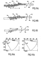
figures 9A et 9B illustrent des premières et deuxièmes portions de la partie de paroi desfigures 7A à 7C couvertes par trois sondes à réseau de phase pour des secteurs angulaires compris entre 30° et 70° et respectivement orientés selon des premier et second sens longitudinaux, - la
figure 10 illustre une troisième portion d'une partie d'une paroi couverte par une sonde à réseau de phase placée sur la surface interne, pour un secteur angulaire compris entre 30° et 70° orienté selon un sens longitudinal, et - les
figures 11A et 11B illustrent deux exemples de cartes obtenues sur une même paroi d'un axe d'essieu.
- the
figure 1 illustrates schematically, in a longitudinal sectional view, an example of a tubular axle axis devoid of equipment, - the
figure 2 illustrates schematically, in a longitudinal sectional view, a part of an example of a tubular axle axis provided with equipment, - the
figure 3 schematically and functionally illustrates an exemplary embodiment of a control apparatus according to the invention, - the
Figures 4A and 4B schematically illustrate two examples of probe placement at two different selected locations of the outer surface of a portion of an axis wall (in a perspective view), for longitudinal analysis, - the
figure 5 schematically illustrates an example of probe placement at a selected location on the outer surface of a portion of an axis wall (in a perspective view), for cross-sectional analysis, - the
figure 6 schematically illustrates an example of probe placement on a selected location of the inner surface of a portion of an axis wall (in a perspective view), for longitudinal analysis, - the
Figures 7A to 7C represent first portions of a portion of a wall covered by three monodirectional probes moved longitudinally from right to left for emission angles respectively equal to 30 °, 45 ° and 60 ° oriented in a first longitudinal direction, - the
Figures 8A to 8C illustrate second portions of the wall portion ofFigures 7A to 7C covered by the same three monodirectional probes moved longitudinally from left to right for emission angles respectively equal to 30 °, 45 ° and 60 ° oriented in a second longitudinal direction, - the
Figures 9A and 9B illustrate first and second portions of the wall portion ofFigures 7A to 7C covered by three phase grating probes for angular sectors between 30 ° and 70 ° and respectively oriented in first and second longitudinal directions, - the
figure 10 illustrates a third portion of a portion of a wall covered by a phase grating probe placed on the inner surface, for an angular sector between 30 ° and 70 ° oriented in a longitudinal direction, and - the
Figures 11A and 11B illustrate two examples of maps obtained on the same wall of an axle axis.
Les dessins annexés pourront non seulement servir à compléter l'invention, mais aussi contribuer à sa définition, le cas échéant.The attached drawings may not only serve to complete the invention, but also contribute to its definition, if any.
L'invention a pour but de permettre le contrôle non destructif manuel de la plus grande partie, et si possible la totalité, d'un axe d'essieu tubulaire, y compris lorsque ce dernier est pourvu d'équipements.The object of the invention is to allow manual non-destructive testing of most, if possible all, of a tubular axle axle, even when equipped with equipment.
On considère dans ce qui suit que les axes tubulaires à contrôler sont destinés à faire partie d'essieux de wagons de transport de marchandise(s) ou de passagers. Mais, l'invention n'est pas limitée à cette application. Elle concerne en effet tout type de produit de révolution creux (tubulaire), soumis à des contraintes en service, comme par exemple des efforts en fatigue, et dont la paroi comprend des profils de rayons extérieur et intérieur variables et connus.In what follows it is considered that the tubular axes to be controlled are intended to be part of the axles of freight wagons (s) or passengers. But, the invention is not limited to this application. It concerns indeed any type of hollow (tubular) revolution product, subjected to stresses in service, such as for example fatigue forces, and whose wall comprises known and variable external and internal ray profiles.
Comme cela est illustré sur la
Le contrôle manuel d'un axe de ce type, qu'il soit dépourvu d'équipements comme dans l'exemple de la
Un tel appareil comprend au moins une sonde à ultrasons SU (ici cinq sont représentées), un module de contrôle MC et un module de traitement MT, ainsi que de préférence un écran EC. On notera que le module de contrôle MC, le module de traitement MT et l'écran EC peuvent faire partie d'un micro-ordinateur (ou d'une station de travail) MO connecté aux sondes SU, comme illustré à titre d'exemple non limitatif sur la
Lorsque l'axe d'essieu AE à contrôler n'est pas monté sur un wagon (comme illustré sur la
Les sondes à ultrasons SU peuvent être soit agencées de manière à émettre des ultrasons suivant une unique direction dont l'angle est choisi mais peut varier en fonction des besoins, soit du type dit à réseau de phase (ou « phased array »), c'est-à-dire agencées de manière à émettre des ultrasons suivant plusieurs directions comprises dans un secteur angulaire choisi en fonction des besoins (grâce à un balayage angulaire électronique). On peut également obtenir l'équivalent d'un déplacement longitudinal du capteur au moyen d'un balayage électronique.The ultrasound probes SU may be either arranged to emit ultrasound in a single direction whose angle is chosen but may vary depending on the needs, either of the type called phase-array (or "phased array"), c that is, arranged to emit ultrasound in a plurality of directions within an angular sector chosen according to the needs (by virtue of an electronic angular scanning). It is also possible to obtain the equivalent of a longitudinal displacement of the sensor by means of an electronic scanning.
Dans le premier cas (monodirectionnel), chaque sonde SU comprend un unique élément de détection chargé de recevoir les échos provenant de la paroi PA objet de l'analyse. Dans le second cas (sonde à réseau de phase), chaque sonde SU comprend plusieurs éléments de détection chargés de recevoir les échos provenant de la paroi PA objet de l'analyse après réfraction et/ou réflexions (éventuellement multiples) sous différents angles. Il est rappelé que les éléments de détection sont généralement réalisés dans un matériau composite et placés sur des transducteurs. Lorsque les éléments de détection d'une sonde sont excités, ils produisent un faisceau d'analyse divergent. La forme de ce dernier et donc sa direction générale d'incidence peuvent être modifiées électroniquement en introduisant des retards temporels au niveau des instants d'excitation d'éléments de détection choisis d'une sonde. On appelle généralement « sonde virtuelle » la combinaison d'éléments de détection d'une sonde et des éventuels retards temporels associés qui sont utilisés pour produire un faisceau d'analyse dans une direction générale donnée. Une sonde à réseau de phase peut ainsi constituer plusieurs (par exemple plusieurs dizaines) sondes virtuelles en fonction des combinaisons dont elle fait l'objet. La fréquence d'excitation des transducteurs est typiquement de l'ordre de quelques mégahertz (2 à 5 MHz). Lorsqu'ils ne sont pas excités en émission, ces mêmes éléments de détection servent à la détection des échos provenant des interfaces matière/air ou matière/liquide, des imperfections et des défauts. Ils constituent ainsi des capteurs de type émetteur/récepteur.In the first case (monodirectional), each probe SU comprises a single detection element responsible for receiving the echoes from the wall PA object of the analysis. In the second case (phase grating probe), each probe SU comprises several detection elements responsible for receiving the echoes from the wall PA object of the analysis after refraction and / or reflections (possibly multiple) from different angles. It is recalled that the detection elements are generally made of a composite material and placed on transducers. When the sensing elements of a probe are excited, they produce a divergent analysis beam. The shape of the latter and therefore its general direction of incidence can be modified electronically by introducing time delays at the moments of excitation of selected detection elements of a probe. The combination of probe sensing elements and any associated time delays that are used to produce an analysis beam in a given general direction is generally referred to as a "virtual probe". A phase array probe can thus constitute several (for example several tens) virtual probes according to the combinations of which it is the subject. The excitation frequency of the transducers is typically of the order of a few megahertz (2 to 5 MHz). When they are not excited in emission, these same detection elements are used to detect echoes from material / air or material / liquid interfaces, imperfections and defects. They thus constitute transmitter / receiver type sensors.
Les profils de rayons interne R2 et externe R1 que présente la paroi PA et les éventuels encombrement et environnement de l'axe AE sont analysés, par exemple au moyen d'un logiciel de simulation de type CIVA 8.0 (développé et commercialisé par le Commissariat à l'Energie Atomique (CEA)), de manière à déterminer le nombre de sondes SU qui vont être nécessaires pour analyser l'intégralité ou une partie choisie seulement de l'axe AE, compte tenu de leur type (monodirectionnel ou à réseau de phase (et dans ce second cas de leur nombre d'éléments de détection)) et du fait qu'elles peuvent être orientées de manière à effectuer des analyses longitudinales ou transversales selon des premier et second sens opposés.The internal R2 and external R1 radii profiles presented by the wall PA and any congestion and environment of the axis AE are analyzed, for example by means of a simulation software of CIVA 8.0 type (developed and marketed by the Office of the Atomic Energy (CEA)), in order to determine the number of SU probes that will be necessary to analyze all or only a selected part of the AE axis, given their type (monodirectional or phase network). (and in this second case their number of sensing elements)) and that they can be oriented to perform longitudinal or transverse analyzes in first and second opposite directions.
On entend ici par « analyse longitudinale » une analyse effectuée en vue de rechercher des défauts et/ou des imperfections orientés préférentiellement longitudinalement ou selon un faible angle aiguë par rapport à la direction longitudinale XX (angle aiguë typiquement inférieur à ±25°, et de préférence inférieur à ±5°). On emploie parfois le terme d'obliquité pour désigner cette orientation du défaut. Cette analyse est effectuée au moyen d'un faisceau émis suivant une direction perpendiculaire à la direction longitudinale XX, c'est-à-dire dont la direction générale est sensiblement contenue dans un plan perpendiculaire à la direction longitudinale XX ou bien qui fait un faible angle aiguë (typiquement inférieur à ±10°) avec cette direction perpendiculaire."Longitudinal analysis" is here understood to mean an analysis carried out with a view to looking for defects and / or imperfections oriented preferentially longitudinally or at a low acute angle with respect to the longitudinal direction XX (acute angle typically less than ± 25 °), and of preferably less than ± 5 °). The term obliquity is sometimes used to designate this orientation of the defect. This analysis is carried out by means of a beam emitted in a direction perpendicular to the longitudinal direction XX, that is to say whose general direction is substantially contained in a plane perpendicular to the longitudinal direction XX or which makes a weak acute angle (typically less than ± 10 °) with this perpendicular direction.
Par ailleurs, on entend ici par « analyse transversale » une analyse effectuée en vue de rechercher des défauts et/ou des imperfections orientés préférentiellement transversalement ou selon un faible angle aiguë par rapport à un plan perpendiculaire à la direction longitudinale XX (angle aiguë typiquement inférieur à ±25°, et de préférence inférieur à ±5°). On emploie parfois le terme d'obliquité pour désigner cette orientation du défaut. Cette analyse est effectuée au moyen d'un faisceau émis suivant une direction parallèle à la direction longitudinale XX, c'est-à-dire dont la direction générale est sensiblement contenue dans un plan qui contient lui-même la direction longitudinale XX ou bien qui fait un faible angle aiguë (typiquement inférieur à ±10°) avec cette direction longitudinale.Moreover, here "cross-analysis" is understood to mean an analysis carried out with a view to looking for defects and / or imperfections oriented preferentially transversely or at a small acute angle with respect to a plane perpendicular to the longitudinal direction XX (typically lower acute angle). at ± 25 °, and preferably below ± 5 °). The term obliquity is sometimes used to designate this orientation of the defect. This analysis is performed by means of a beam emitted in a direction parallel to the longitudinal direction XX, that is to say whose general direction is substantially contained in a plane which itself contains the longitudinal direction XX or which makes a low acute angle (typically less than ± 10 °) with this longitudinal direction.
En outre, on entend ici par « environnement de l'axe » le contenu de l'espace qui l'entoure lorsqu'il doit être contrôlé. On comprendra en effet que lorsque l'on doit contrôler un axe AE qui est monté sur un wagon, lui-même placé sur des rails, les portions que l'on peut contrôler peuvent être notablement réduites.In addition, the term "environment of the axis" here means the content of the space that surrounds it when it must be controlled. It will be understood that when controlling an axis AE which is mounted on a wagon, itself placed on rails, the portions that can be controlled can be significantly reduced.
Compte tenu des formes des profils des rayons interne R2 et externe R1 que présente habituellement la paroi PA des axes AE et des éventuels encombrement et environnement de ces derniers, l'angle d'émission d'une sonde SU monodirectionnelle doit généralement pouvoir varier entre environ 0° et environ 70° par rapport à la direction longitudinale XX, et le secteur angulaire d'émission d'une sonde SU à réseau de phase doit généralement être compris entre environ 0° et environ 70° par rapport à la direction longitudinale XX.Given the shape of the profiles of the inner radius R2 and external R1 that usually presents the wall PA of the axes AE and any congestion and environment of the latter, the emission angle of a monodirectional SU probe must generally be able to vary between 0 ° and about 70 ° with respect to the longitudinal direction XX, and the angular sector of emission of a phase array probe SU must generally be between about 0 ° and about 70 ° with respect to the longitudinal direction XX.
Une fois que le module de contrôle MC a déterminé pour chaque sonde SU le (premier) endroit choisi où elle va devoir être initialement et manuellement placée relativement à l'axe AE de manière à analyser une première portion choisie de la paroi PA dans un premier secteur angulaire choisi, orienté suivant un premier sens longitudinal ou transversal, ainsi que l'éventuel (second) endroit choisi où elle va devoir être ultérieurement et manuellement placée relativement à l'axe AE de manière à analyser une deuxième portion choisie de la paroi PA dans un deuxième secteur angulaire choisi, orienté suivant un second sens longitudinal ou transversal opposé au premier sens, on peut placer manuellement les sondes SU en leurs premiers endroits choisis respectifs.Once the control module MC has determined for each probe SU the (first) chosen place where it will have to be initially and manually placed relative to the axis AE so as to analyze a first selected portion of the wall PA in a first selected angular sector, oriented in a first longitudinal or transverse direction, as well as the possible (second) chosen location where it will have to be later and manually placed relative to the axis AE so as to analyze a second selected portion of the wall PA in a second selected angular sector, oriented in a second longitudinal or transverse direction opposite to the first direction, the SU probes can be placed manually at their respective first selected locations.
Ce placement manuel des sondes SU relativement à l'axe AE peut se faire en des premiers endroits choisis qui sont situés soit sur la surface externe SE de la paroi PA, soit sur la surface interne SI de cette paroi PA, selon les besoins (et la configuration de l'axe AE). On peut par exemple commencer par effectuer des analyses par ultrasons en plaçant des sondes SU sur la surface externe SE de la paroi PA, puis éventuellement compléter ces analyses en plaçant ensuite des sondes SU sur la surface interne SI de la paroi PA (c'est-à-dire à l'intérieur de l'axe tubulaire AE). Mais l'inverse est également possible.This manual placement of the probes SU relative to the axis AE can be done at first selected locations which are located either on the outer surface SE of the wall PA, or on the internal surface SI of this wall PA, as required (and the configuration of the AE axis). For example, it is possible to start by performing ultrasound analyzes by placing SU probes on the outer surface SE of the wall PA, and then possibly completing these analyzes by then placing probes SU on the internal surface SI of the PA wall (that is to say inside the tubular axis AE). But the opposite is also possible.
Le couplage entre les sondes SU et la surface interne SI ou externe SE d'une paroi PA peut se faire par tout moyen connu de l'homme de l'art, et notamment au moyen de glycérine ou par immersion dans de l'eau de préférence mélangée avec un produit anticorrosif.The coupling between the probes SU and the internal surface SI or external SE of a wall PA can be done by any means known to those skilled in the art, and in particular by means of glycerine or by immersion in water of preferably mixed with an anticorrosive product.
On a représenté sur les
Il est important de noter qu'une sonde SU peut analyser une portion qui lui a été attribuée soit en étant maintenue au niveau d'un endroit choisi, soit en étant déplacée manuellement par un technicien, longitudinalement et/ou transversalement, entre une position de départ (correspondant à l'endroit initialement choisi) et une position de fin (correspondant à un autre endroit choisi), éventuellement via une ou plusieurs positions intermédiaires (correspondant chacune à un autre endroit choisi).It is important to note that an SU probe can analyze a portion that has been assigned to it either by being held at a selected location or by being manually moved by a technician, longitudinally and / or transversely, between a position of departure (corresponding to the location initially chosen) and an end position (corresponding to another chosen location), possibly via one or more intermediate positions (each corresponding to another chosen location).
Au lieu de déplacer manuellement certaines sondes SU, ou bien en complément d'un tel déplacement, elles peuvent être utilisées en mode de balayage électronique, sous le contrôle du module de contrôle MC, pour analyser une partie au moins des portions d'une paroi PA. Il est rappelé qu'un balayage électronique est obtenu pour une sonde SU en utilisant certains de ces éléments de détection situés à des emplacements choisis de son réseau de phase et en attribuant des délais choisis à ces éléments de détection choisis de sorte qu'ils émettent séquentiellement. Ce mode de déplacement « électronique » est avantageux car il évite d'avoir à déplacer manuellement une sonde SU.Instead of manually moving certain probes SU, or in addition to such displacement, they can be used in electronic scanning mode, under the control of the control module MC, to analyze at least part of the portions of a wall PA. It is recalled that an electronic scanning is obtained for an SU sensor by using some of these detection elements located at selected locations of its phase grating and assigning selected delays to these selected detection elements so that they emit sequentially. This "electronic" mode of travel is advantageous because it avoids having to manually move an SU probe.
Le module de contrôle MC est chargé de déterminer, en fonction des profils interne et externe de l'axe AE à contrôler et des éventuels encombrement et environnement de ce dernier, au moins des premiers et deuxièmes endroits choisis sur la surface externe SE ou interne SI de la paroi PA où doivent être placées manuellement les sondes SU afin qu'elles analysent des premières et deuxièmes portions choisies de la paroi PA respectivement dans des premiers et deuxièmes secteurs angulaires choisis, orientés suivant des premier et second sens longitudinaux (direction XX) ou transversaux (direction perpendiculaire à la direction XX) opposés, et qu'elles acquièrent ainsi des données d'analyse pour différentes positions angulaires relatives de l'axe AE par rapport aux sondes SU.The control module MC is responsible for determining, according to the internal and external profiles of the AE axis to be controlled and any congestion and environment of the latter, at least first and second locations chosen on the external surface SE or internal SI of the wall PA where the probes SU are to be placed manually so that they analyze selected first and second portions of the wall PA respectively in selected first and second angular sectors, oriented along first and second longitudinal directions (direction XX) or crosswise (direction perpendicular to the direction XX) opposite, and they thus acquire analysis data for different relative angular positions of the axis AE with respect to the probes SU.
On notera que la solution utilisée pour analyser toute une portion de paroi PA choisie dépend du type de sonde SU disponible et en outre, dans le cas de sondes à réseau de phase, du nombre d'éléments de détection qui les constituent. En effet, on comprendra que si le nombre d'éléments de détection d'une sonde SU est adapté à la couverture de la portion de paroi PA qui lui a été attribuée, il est inutile de prévoir un déplacement longitudinal manuel car on peut lui substituer un balayage électronique. A titre d'exemple, si une sonde SU doit couvrir une portion de paroi PA d'extension longitudinale égale à 100 mm, alors elle doit comporter au moins 200 éléments de détection de 0,5 mm de côté, par exemple séparés deux à deux d'une distance égale à environ 0,1 mm. Il est rappelé que plus les dimensions des éléments de détection sont petites, plus les secteurs angulaires d'analyse peuvent être larges. Un compromis peut être trouvé entre le nombre d'éléments de détection des sondes SU et les possibilités d'extension de couverture offertes par le balayage électronique, de manière à éviter les déplacements longitudinaux manuels.It will be noted that the solution used to analyze an entire wall portion PA chosen depends on the type of probe SU available and, in the case of phase-array probes, on the number of detection elements that constitute them. Indeed, it will be understood that if the number of detection elements of a probe SU is adapted to the coverage of the wall portion PA which has been allocated to it, it is unnecessary to provide a manual longitudinal movement because it can be substituted an electronic scan. By way of example, if a probe SU must cover a wall portion PA of longitudinal extension equal to 100 mm, then it must comprise at least 200 detection elements of 0.5 mm side, for example separated two by two a distance of about 0.1 mm. It is recalled that the smaller the dimensions of the detection elements, the larger the angular areas of analysis can be. A compromise can be found between the number of detection elements of the SU probes and the coverage extension possibilities offered by the electronic scanning, so as to avoid manual longitudinal movements.
On notera également que l'utilisation de sondes à réseau de phase est plus avantageuse que celle de sondes monodirectionnelles car elle permet d'obtenir une meilleure continuité sur un même secteur angulaire d'analyse tout en évitant tout déplacement angulaire de la source d'ultrasons.It should also be noted that the use of phase array probes is more advantageous than that of unidirectional probes because it makes it possible to obtain a better continuity on the same angular sector of analysis while avoiding any angular displacement of the ultrasound source. .
Selon l'invention, une fois que les sondes SU ont été placées manuellement sur la surface externe SE ou interne SI d'une paroi PA en des premiers endroits (choisis en fonction de ses profils et des éventuels encombrement et environnement de l'axe AE), chacune de ces sondes SU procède à l'analyse de la première portion de la paroi PA, qui a été déterminée pour elle par le module de contrôle MC, dans un premier secteur angulaire choisi qui est orienté suivant un premier sens longitudinal ou transversal. Chaque sonde SU peut ainsi acquérir des données d'analyse pour la position angulaire courante relative de l'axe AE par rapport à ladite sonde SU. En déplaçant angulairement les sondes SU par rapport à l'axe AE sur des secteurs angulaires successifs choisis, chaque sonde SU peut effectuer une nouvelle acquisition de données d'analyse après chaque déplacement angulaire. On peut ainsi disposer de données d'analyse relatives à l'intégralité de la circonférence de chaque première portion de paroi PA inspectée.According to the invention, once the SU probes have been placed manually on the outer SE or inner surface SI of a wall PA at first locations (chosen according to its profiles and any congestion and environment of the axis AE ), each of these probes SU performs the analysis of the first portion of the wall PA, which has been determined for it by the control module MC, in a first selected angular sector which is oriented in a first longitudinal or transverse direction . Each probe SU can thus acquire analysis data for the current relative angular position of the axis AE with respect to said probe SU. By angularly moving the probes SU with respect to the axis AE on selected successive angular sectors, each probe SU can carry out a new acquisition of analysis data after each angular displacement. Thus, analysis data relating to the entire circumference of each first portion of PA wall inspected may be available.
Ces données d'analyse comprennent par exemple les angles d'émission, les instants d'émission et de réception des ultrasons (ou ce qui est équivalent les intervalles temporels entre les instants d'émission et de réception), et les angles de réception. Elles sont par exemple transmises par les sondes SU au module de contrôle MC qui se charge de les stocker dans une mémoire MY en correspondance des positions longitudinales et angulaires des premières portions inspectées par rapport à un référentiel choisi, ainsi qu'éventuellement de l'identifiant de la sonde SU utilisée pour les obtenir.This analysis data includes, for example, the transmission angles, the transmission and reception times of the ultrasound (or what is equivalent the time intervals between the transmission and reception instants), and the reception angles. For example, they are transmitted by the probes SU to the control module MC, which is responsible for storing them in a memory MY in correspondence of the longitudinal and angular positions of the first portions inspected with respect to a chosen reference frame, as well as possibly of the identifier of the SU probe used to obtain them.
Ensuite, certaines au moins des sondes SU sont replacées manuellement sur la surface externe SE ou interne SI de la paroi PA en des deuxièmes endroits (choisis en fonction de ses profils et des éventuels encombrement et environnement de l'axe AE) afin qu'elles procèdent à l'analyse des deuxièmes portions de la paroi PA qui leur ont été respectivement attribuées, dans des deuxièmes secteurs angulaires choisis qui sont orientés suivant un second sens longitudinal ou transversal, opposé au premier sens.Then, at least some of the probes SU are manually replaced on the external surface SE or internal SI of the wall PA in second places (chosen according to its profiles and any congestion and environment of the axis AE) so that they proceed to the analysis of the second portions of the wall PA which have respectively been assigned to them, in second selected angular sectors which are oriented in a second longitudinal or transverse direction, opposite to the first direction.
Par exemple, si le premier sens correspond à un sens allant de la gauche vers la droite de l'axe longitudinal XX, alors le second sens correspond à un sens allant de la droite vers la gauche dudit axe longitudinal XX. De même, si le premier sens correspond à un sens allant de la gauche vers la droite d'un second axe perpendiculaire à l'axe longitudinal XX, alors le second sens correspond à un sens allant de la droite vers la gauche dudit second axe.For example, if the first direction corresponds to a direction going from the left to the right of the longitudinal axis XX, then the second direction corresponds to a direction going from the right to the left of said longitudinal axis XX. Similarly, if the first direction corresponds to a direction from the left to the right of a second axis perpendicular to the longitudinal axis XX, then the second direction corresponds to a direction going from the right to the left of said second axis.
Chaque sonde SU replacée manuellement peut ainsi acquérir des données d'analyse pour sa position angulaire courante par rapport à l'axe AE. En déplaçant angulairement les sondes SU par rapport à l'axe AE sur des secteurs angulaires choisis, chaque sonde SU peut effectuer une nouvelle acquisition de données d'analyse après chaque déplacement angulaire. On peut ainsi disposer de données d'analyse relatives à l'intégralité de la circonférence de chaque deuxième portion de paroi PA inspectée. Ces données d'analyse sont par exemple transmises par les sondes SU au module de contrôle MC qui se charge de les stocker dans une mémoire en correspondance des positions longitudinales et angulaires des deuxièmes portions inspectées par rapport à un référentiel choisi, ainsi qu'éventuellement de l'identifiant de la sonde SU utilisée pour les obtenir.Each probe SU replaced manually can thus acquire analysis data for its current angular position with respect to the axis AE. By angularly moving the probes SU with respect to the axis AE on selected angular sectors, each probe SU can carry out a new acquisition of analysis data after each angular displacement. It is thus possible to have analysis data relating to the entire circumference of each second portion of PA wall inspected. These analysis data are, for example, transmitted by the probes SU to the control module MC, which is responsible for storing them in a memory corresponding to the longitudinal and angular positions of the second portions inspected with respect to a chosen reference frame, as well as possibly of the identifier of the SU probe used to obtain them.
Grâce à cette double analyse selon des sens opposés, on peut inspecter tout ou partie d'un axe d'essieu AE (selon les besoins), comme cela ressort des
- les
figures 7A à 7C représentent les premières portions d'une partie d'une paroi qui peuvent être couvertes par trois sondes monodirectionnelles, placées sur la surface externe SE et déplacées longitudinalement de la droite vers la gauche, pour des angles d'émission respectivement égaux à 30°, 45° et 60° orientés selon un premier sens longitudinal (allant de la droite vers la gauche), - les
figures 8A à 8C représentent les deuxièmes portions de cette même partie de paroi qui peuvent être couvertes par les trois mêmes sondes monodirectionnelles, placées sur la surface externe SE et déplacées longitudinalement de la gauche vers la droite, pour des angles d'émission respectivement égaux à 30°, 45° et 60° orientés selon un second sens longitudinal (allant de la gauche vers la droite), - la
figure 9A représente les premières portions de cette même partie de paroi qui peuvent être couvertes par trois sondes à réseau de phase, placées sur la surface externe SE, pour un secteur angulaire compris entre 30° et 70° orienté selon un premier sens longitudinal (allant de la droite vers la gauche), - la
figure 9B représente les deuxièmes portions de cette même partie de paroi qui peuvent être couvertes par les trois mêmes sondes à réseau de phase, placées sur la surface externe SE, pour un secteur angulaire compris entre 30° et 70° orienté selon un second sens longitudinal (allant de la gauche vers la droite), et - la
figure 10 représente les troisièmes portions de cette même partie de paroi qui peuvent être couvertes par une sonde à réseau de phase, placée sur la surface interne SI, pour un secteur angulaire compris entre 30° et 70° orienté selon un sens longitudinal (allant de la gauche vers la droite).
- the
Figures 7A to 7C represent the first portions of a part of a wall that can be covered by three monodirectional probes, placed on the external surface SE and moved longitudinally from right to left, for emission angles respectively equal to 30 °, 45 ° and 60 ° oriented in a first longitudinal direction (from right to left), - the
Figures 8A to 8C represent the second portions of this same wall portion that can be covered by the same three monodirectional probes, placed on the outer surface SE and moved longitudinally from left to right, for emission angles respectively equal to 30 °, 45 ° and 60 ° oriented in a second longitudinal direction (from left to right), - the
Figure 9A represents the first portions of this same wall portion that can be covered by three phase grating probes, placed on the outer surface SE, for an angular sector between 30 ° and 70 ° oriented in a first longitudinal direction (ranging from right to the left), - the
Figure 9B represents the second portions of this same wall portion which can be covered by the same three phase grating probes, placed on the outer surface SE, for an angular sector between 30 ° and 70 ° oriented in a second longitudinal direction ( from left to right), and - the
figure 10 represents the third portions of this same wall portion which can be covered by a phase grating probe, placed on the inner surface SI, for an angular sector between 30 ° and 70 ° oriented in a longitudinal direction (from the left to the right).
Compte tenu des formes des profils des rayons interne R2 et externe R1 que présente habituellement la paroi PA des axes AE et des éventuels encombrement et environnement de ces derniers, l'angle d'émission d'une sonde SU monodirectionnelle doit généralement pouvoir varier entre environ 0° et environ 70° par rapport à la direction longitudinale XX ou transversale, et le secteur angulaire d'émission d'une sonde SU à réseau de phase doit généralement être compris entre environ 0° et environ 70° par rapport à la direction longitudinale XX ou transversale.Given the shape of the profiles of the inner radius R2 and external R1 that usually presents the wall PA of the axes AE and any congestion and environment of the latter, the emission angle of a monodirectional SU probe must generally be able to vary between 0 ° and about 70 ° relative to the longitudinal direction XX or transverse, and the angular sector of emission of a phase array probe SU must generally be between about 0 ° and about 70 ° with respect to the longitudinal direction XX or transverse.
Sur les exemples des
Les données d'analyse stockées sont extraites par le module de traitement MT, qui se charge alors de les regrouper en fonction des zones d'axe qu'elles concernent de manière à constituer des cartes qui représentent les orientations transversales ou longitudinales et les positions d'indications d'échos au sein de la paroi PA.The stored analysis data are extracted by the processing module MT, which is then responsible for grouping them according to the axis zones that they concern so as to constitute maps that represent the transverse or longitudinal orientations and the positions of echo indications within the PA wall.
Il est rappelé que les indications d'échos résultent d'une réflexion soit sur une interface matière/air ou matière/liquide, soit sur une imperfection, soit encore sur un défaut.It is recalled that the echo indications result from a reflection on either a material / air or material / liquid interface, or on an imperfection, or on a defect.
Il est également rappelé que les analyses longitudinales sont plus particulièrement adaptées à la détection d'imperfections et de défauts transversaux (qui sont généralement les plus fréquents), tandis que les analyses transversales sont plus particulièrement adaptées à la détection d'imperfections et de défauts longitudinaux.It is also recalled that the longitudinal analyzes are more particularly adapted to the detection of imperfections and transverse defects (which are generally the most frequent), while the transverse analyzes are more particularly adapted to the detection of imperfections and longitudinal defects .
Le fait d'inspecter des matériaux selon deux sens opposés et donc selon des directions d'analyse très différentes permet de détecter des imperfections et des défauts de plus petites dimensions, et donc un plus grand nombre d'imperfections et de défauts qu'avec les procédés et appareils de contrôle de l'art antérieur adaptés aux axes pleins (ou massifs). Mais cela permet également une bonne détection des imperfections et des défauts obliques et inclinés (ou « tiltés ») à l'intérieur de la paroi PA.The fact of inspecting materials in two opposite directions and thus in very different directions of analysis makes it possible to detect imperfections and defects of smaller dimensions, and thus a greater number of imperfections and defects than with the methods and apparatus for controlling the prior art adapted to solid (or massive) axes. But it also allows a good detection of imperfections and oblique defects (or "tilted") inside the wall PA.
On notera que le module de traitement MT peut éventuellement être agencé de manière à effectuer des « corrélations » entre données d'analyse relatives à des zones identiques constituant les zones de recouvrement de première(s) et/ou deuxième(s) portions de paroi. Ils peuvent ainsi constituer des cartes « brutes » de ces zones de recouvrement, éventuellement de type tridimensionnel (3D).It will be noted that the processing module MT may optionally be arranged in such a way as to make "correlations" between analysis data relating to identical zones constituting the zones of overlap of first (s) and / or second (s) wall portions. . They can thus constitute "raw" maps of these areas of recovery, possibly of three-dimensional type (3D).
Les fichiers de données constituant les cartes brutes sont de préférence stockés dans une mémoire MY. Ces cartes peuvent alors être soit affichées de façon individualisée (les unes après les autres) ou de façon groupée (plusieurs en même temps) sur l'écran EC en vue d'une analyse par un technicien, soit d'abord analysées de façon automatisée, puis converties en cartes « corrigées » ou cartes « de défauts » qui peuvent être affichées sur l'écran EC de façon individualisée ou de façon groupée.The data files constituting the raw cards are preferably stored in a memory MY. These cards can then either be displayed individually (one after the other) or grouped (several at the same time) on the EC screen for analysis by a technician, or first analyzed in an automated way and then converted into "corrected" or "fault" cards that can be displayed on the EC screen individually or in a grouped manner.
Plusieurs types d'analyses comparatives peuvent être effectuées sur les cartes « brutes ».Several types of comparative analysis can be performed on "raw" cards.
Par exemple, le module de traitement MT peut être chargé de comparer les données de certaines au moins des cartes, qui ont été obtenues sur un axe AE à contrôler, à des données de premières cartes étalons qui ont été obtenues sur un premier axe étalon du même type que celui contrôlé, mais dépourvu de défauts. Dans ce cas, le module de traitement MT ne retient que les données qui sont représentatives d'indications d'échos qui ne sont pas présentes dans les premières cartes étalons, afin de constituer des cartes corrigées qu'il stocke dans la mémoire MY.For example, the processing module MT may be responsible for comparing the data of at least some of the cards, which have been obtained on an AE axis to be checked, with data of first standard cards which have been obtained on a first standard axis of the same type as the one checked, but without defects. In this case, the processing module MT retains only the data that is representative of echo indications that are not present in the first standard cards, in order to constitute corrected cards that it stores in the memory MY.
En variante ou en complément, le module de traitement MT peut être chargé de comparer les données de certaines au moins des cartes (brutes ou corrigées) qui ont été obtenues sur un axe AE à des données de secondes cartes étalons qui ont été obtenues sur un second axe étalon de même type que celui contrôlé, mais comportant des défauts connus. Dans ce cas, le module de traitement MT ne retient que les données qui sont représentatives d'indications d'échos représentatives de défauts connus présents dans les secondes cartes étalons, afin de constituer des cartes de défauts qu'il stocke dans la mémoire MY.Alternatively or in addition, the processing module MT may be responsible for comparing the data of at least some of the cards (raw or corrected) that have been obtained on an axis AE with data of second standard cards which have been obtained on a second standard axis of the same type as the one checked, but with known defects. In this case, the processing module MT retains only the data which are representative of indications of echoes representative of known defects present in the second standard cards, in order to constitute fault cards which it stores in the memory MY.
En variante ou en complément, le module de traitement MT peut être chargé de comparer à une amplitude seuil choisie les amplitudes des indications d'échos représentées sur certaines au moins des cartes. Dans ce cas, le module de traitement MT ne retient que les données qui sont représentatives d'indications d'échos dont les amplitudes sont supérieures à l'amplitude seuil choisie et qui de ce fait sont censées être issues de défauts, afin de constituer des cartes de défauts.As a variant or in addition, the processing module MT may be responsible for comparing, with a selected threshold amplitude, the amplitudes of the echo indications represented on at least some of the cards. In this case, the processing module MT retains only those data which are representative of echo indications whose amplitudes are greater than the chosen threshold amplitude and which are therefore supposed to be derived from defects, in order to constitute fault cards.
Par ailleurs, on peut également envisager que le module de traitement MT génère une alarme (sonore et/ou visuelle (affichée sur l'écran EC)) chaque fois qu'il détecte qu'une amplitude est supérieure à l'amplitude seuil choisie.Moreover, it can also be envisaged that the processing module MT generates an alarm (sound and / or visual (displayed on the screen EC)) each time it detects that an amplitude is greater than the chosen threshold amplitude.
On a représenté sur les
Comme indiqué précédemment, on peut analyser une paroi PA en plaçant manuellement les sondes SU sur sa surface externe SE ou bien sur sa surface interne SI. Mais, on peut également envisager d'effectuer une double analyse, par exemple en commençant par placer manuellement les sondes SU sur sa surface externe SE puis en plaçant manuellement certaines des sondes SU sur sa surface interne SI. Plus précisément, dans ce cas on place manuellement les sondes SU sur la surface externe SE de la paroi PA en des premiers endroits choisis et on analyse avec ces sondes SU des premières portions choisies de la paroi PA dans des premiers secteurs angulaires choisis, orientés suivant un premier sens longitudinal (ou transversal), afin d'acquérir des données d'analyse pour différentes positions angulaires des sondes SU par rapport à l'axe AE. Puis, on replace manuellement certaines au moins des sondes SU sur la surface externe SE de la paroi PA en des deuxièmes endroits choisis et on analyse avec ces sondes SU des deuxièmes portions choisies de la paroi PA dans des deuxièmes secteurs angulaires choisis, orientés suivant un second sens longitudinal (ou transversal), opposé au premier, afin d'acquérir des données d'analyse pour différentes positions angulaires des sondes SU par rapport à l'axe AE. Enfin, on place manuellement certaines au moins des sondes SU sur la surface interne SI de la paroi PA en des troisièmes endroits choisis et on analyse avec ces sondes SU des troisièmes portions choisies de la paroi PA dans des troisièmes secteurs angulaires choisis, orientés suivant au moins un sens longitudinal (ou transversal), voire même deux sens opposés, afin d'acquérir des données d'analyse pour différentes positions angulaires des sondes SU par rapport à l'axe AE.As indicated above, a PA wall can be analyzed by manually placing the probes SU on its outer surface SE or on its inner surface SI. But we can also consider performing a double analysis, for example by manually starting the SU probes on its outer surface SE and then manually placing some of the SU probes on its internal surface SI. More precisely, in this case, the probes SU are manually placed on the outer surface SE of the wall PA at the first selected locations and, with these probes SU, the first selected portions of the wall PA are analyzed in first selected angular sectors oriented next a first longitudinal direction (or transverse), in order to acquire analysis data for different angular positions of the probes SU with respect to the axis AE. Then, at least some of the probes SU are manually replaced on the outer surface SE of the wall PA at the second selected locations and, with these probes SU, the selected second portions of the wall PA are analyzed in second selected angular sectors, oriented along a second longitudinal direction (or transverse), opposite to the first, in order to acquire analysis data for different angular positions of the probes SU with respect to the axis AE. Finally, at least some of the probes SU are manually placed on the inner surface SI of the wall PA at the third selected locations and, with these probes SU, the selected third portions of the wall PA are analyzed in selected third angular sectors, oriented according to FIG. least one longitudinal direction (or transverse), or even two opposite directions, in order to acquire analysis data for different angular positions of the probes SU with respect to the axis AE.
Le module de traitement MT constitue alors, à partir de l'ensemble des données d'analyse, des cartes représentatives des positions et orientations des indications d'échos au sein de la paroi PA.The processing module MT then constitutes, from the set of analysis data, representative maps of the positions and orientations of the echo indications within the wall PA.
Cette double analyse par l'extérieur et par l'intérieur peut permettre de couvrir la totalité des portions d'une paroi PA à inspecter, alors que cela peut s'avérer impossible au moyen de la seule analyse par l'extérieur, du fait des profils de cette paroi PA et/ou de l'encombrement et/ou l'environnement de l'axe AE.This double analysis from the outside and the inside can cover all of the portions of an AP wall to be inspected, whereas this may be impossible by means of the only analysis by the outside, because of the profiles of this wall PA and / or congestion and / or the environment of the axis AE.
Il est également possible d'effectuer une première analyse longitudinale dans les deux sens (comme indiqué ci-dessus) et par l'extérieur (ou l'intérieur), puis une seconde analyse transversale dans au moins un sens et par l'extérieur (ou par l'intérieur), de manière à constituer des cartes représentatives des orientations transversales et des positions d'indications d'échos au sein de la paroi PA et des cartes représentatives des orientations longitudinales et des positions d'indications d'échos au sein de cette même paroi PA.It is also possible to carry out a first longitudinal analysis in both directions (as indicated above) and from outside (or inside), then a second transverse analysis in at least one direction and from the outside ( or from the inside), in order to constitute representative maps of the transverse orientations and echo indication positions within the PA wall and representative maps of the longitudinal orientations and the echo indication positions within the same PA wall.
Il est également possible d'effectuer une première analyse longitudinale dans les deux sens et par l'extérieur, puis une seconde analyse transversale dans au moins un sens et par l'intérieur.It is also possible to perform a first longitudinal analysis in both directions and from the outside, then a second transversal analysis in at least one direction and from the inside.
Il est également possible d'effectuer une première analyse transversale dans les deux sens et par l'intérieur, puis une seconde analyse dans au moins un sens et par l'extérieur.It is also possible to perform a first cross analysis in both directions and from the inside, then a second analysis in at least one direction and from the outside.
D'unè manière générale, toutes les combinaisons d'analyses longitudinale(s) et transversale(s) par l'intérieur et par l'extérieur peuvent être envisagées.In general, all combinations of longitudinal (s) and transverse (s) analysis from the inside and the outside may be considered.
On notera que les analyses par l'intérieur peuvent dans certains cas nécessiter un réalésage au moins des extrémités de l'axe d'essieu tubulaire AE, de manière à permettre le placement d'au moins une sonde SU à l'intérieur de cet axe AE, contre la surface interne SI de sa paroi PA, ainsi que son éventuel déplacement manuel.Note that the internal analyzes may in certain cases require a reaming of at least the ends of the tubular axle axis AE, so as to allow the placement of at least one probe SU within this axis AE, against the inner surface SI of its wall PA, as well as its possible manual movement.
On notera également que les endroits de placement des sondes SU, les différents angles ou différents secteurs angulaires d'analyse par ultrasons de chacune des sondes SU et les portions de paroi attribuées aux différentes sondes peuvent être éventuellement déterminées par le module de contrôle MC en fonction de contrainte(s). Ainsi, on peut envisager qu'une partie d'un contrôle soit faite avec un faisceau dont la direction générale est sensiblement contenue dans un plan qui contient lui-même la direction longitudinale XX et sur des portions de paroi présentant deux à deux des taux de recouvrement choisis, par exemple 50%, et/ou qu'une partie d'un contrôle soit faite avec des faisceaux successifs dont les directions générales sont sensiblement contenues dans des plans qui font des angles aiguës avec cette direction longitudinale XX qui croissent entre 0° et +20° et entre 0° et -20°. Par ailleurs, l'angle d'inclinaison des éléments de détection d'une sonde SU peut être choisi en fonction des besoins. A titre d'exemple non limitatif, un angle de 45° par rapport à la direction longitudinale XX peut être choisi.It will also be noted that the locations of placement of the probes SU, the different angles or different angular sectors of ultrasonic analysis of each of the probes SU and the wall portions allocated to the different probes may be determined by the control module MC depending of constraint (s). Thus, it can be envisaged that part of a control is made with a beam whose general direction is substantially contained in a plane which itself contains the longitudinal direction XX and on wall portions having two to two chosen covering, for example 50%, and / or that part of a control is made with successive beams whose general directions are substantially contained in planes which make acute angles with this longitudinal direction XX which grow between 0 ° and + 20 ° and between 0 ° and -20 °. Moreover, the angle of inclination of the elements of Detection of an SU sensor can be chosen as needed. By way of nonlimiting example, an angle of 45 ° with respect to the longitudinal direction XX may be chosen.
On notera également, comme le sait l'homme de l'art, que le gain de chaque transducteur doit faire l'objet d'un ajustement pendant une phase de calibration, par exemple pour que l'amplitude du signal obtenu sur le premier écho provenant d'une interface de la paroi PA corresponde à une amplitude égale par exemple à environ 50% de la dynamique totale d'amplitude utilisée pour les cartes.It will also be noted, as is known to one skilled in the art, that the gain of each transducer must be adjusted during a calibration phase, for example so that the amplitude of the signal obtained on the first echo from an interface of the wall PA corresponds to an amplitude equal for example to about 50% of the total amplitude dynamic used for the cards.
Par ailleurs, la phase de calibration comporte également de préférence une première partie dédiée à l'obtention des cartes étalons précitées, qui sont représentatives des résultats d'analyses par ultrasons effectuées sur un axe d'essieu tubulaire étalon du même type que ceux devant faire l'objet d'un contrôle, mais sain (c'est-à-dire dépourvu d'imperfections et de défauts structurels). Cette première partie de la phase de calibration permet en effet de connaître à l'avance les échos qui sont induits par la géométrie de la paroi PA (et notamment les coins et plus généralement les zones dans lesquelles le rayon intérieur R2 ou extérieur R1 varie de façon importante) et ainsi de les différencier de ceux qui sont induits par les imperfections et défauts structurels dans les axes d'essieu tubulaires AE à contrôler.Moreover, the calibration phase also preferably comprises a first part dedicated to obtaining the aforementioned standard maps, which are representative of the results of ultrasonic analyzes carried out on a standard tubular axle axis of the same type as those to be made. subject to control, but sound (ie, free from imperfections and structural defects). This first part of the calibration phase makes it possible to know in advance the echoes which are induced by the geometry of the wall PA (and in particular the corners and more generally the areas in which the inner radius R2 or outer radius R1 varies from important way) and thus to differentiate them from those induced by the imperfections and structural defects in the tubular axles AE AE to control.
De même, la phase de calibration peut également comporter une seconde partie dédiée à l'obtention des cartes étalons précitées, qui sont représentatives des résultats d'analyses par ultrasons effectuées sur un axe d'essieu tubulaire étalon du même type que ceux devant faire l'objet d'un contrôle, mais lequel étalon comprend des défauts structurels ou artificiels caractéristiques (comme par exemple des encoches ou cavités caractéristiques) définis en des endroits choisis. Ces défauts structurels ou artificiels caractéristiques sont définis selon un cahier des charges et/ou des normes qui fixent un seuil de tri entre des imperfections et des défauts. Lorsque l'amplitude du signal provenant des échos sur des défauts naturels est inférieure au seuil de tri on est en présence d'une imperfection. Dans le cas contraire (supérieure au seuil) on est en présence d'un défaut. Cette seconde partie de la phase de calibration permet en effet de connaître à l'avance les échos qui sont induits par des défauts structurels ou artificiels caractéristiques et ainsi de pouvoir plus facilement détecter dans les cartes, par comparaison à un seuil de tri, les « objets » qui induisent des échos (ou signatures) de types similaires dans les axes d'essieu tubulaires AE à contrôler.Similarly, the calibration phase may also include a second part dedicated to obtaining the aforementioned standard cards, which are representative of the results of ultrasonic analyzes performed on a standard tubular axle axis of the same type as those to be made. subject to control, but which standard includes characteristic structural or artificial defects (such as notches or characteristic cavities) defined in selected locations. These characteristic structural or artificial defects are defined according to specifications and / or standards that set a sorting threshold between imperfections and defects. When the amplitude of the signal coming from the echoes on natural defects is lower than the sorting threshold, there is an imperfection. In the opposite case (above the threshold) there is a defect. This second part of the calibration phase makes it possible to know in advance the echoes that are induced by characteristic structural or artificial defects and thus to be able to easily detect in the cards, compared to a sorting threshold, the "objects" that induce echoes (or signatures) of similar types in the tubular axles AE to be controlled.
Une fois que l'on a terminé l'analyse longitudinale et/ou transversale par ultrasons d'un axe d'essieu tubulaire AE, il est ensuite possible d'effectuer manuellement au moins une analyse complémentaire d'un autre type. Par exemple, on peut effectuer une analyse de la surface externe SE de la paroi PA afin d'acquérir des données d'analyse de surface pour différentes positions relatives de l'axe AE par rapport aux moyens d'analyse de surface.Once the longitudinal and / or transverse ultrasound analysis of a tubular axle axis AE has been completed, it is then possible to manually perform at least one additional analysis of another type. For example, an analysis of the outer surface SE of the wall PA can be performed to acquire surface analysis data for different relative positions of the axis AE with respect to the surface analysis means.
Parmi les techniques d'analyse de surface qui peuvent être utilisées, on peut notamment citer celle dite du flux de fuite et celle dite des courants de Foucault. Certaines de ces techniques sont avantageuses du fait qu'elles fournissent des données d'analyse de surface à partir desquelles on peut réaliser des cartes représentatives des positions et orientations des défauts de surface de la paroi PA. Les fichiers de données constituant ces cartes de défauts de surface sont de préférence stockés dans une mémoire MY afin que lesdites cartes de défauts de surface puissent être affichées de façon individualisée (les unes après les autres) ou de façon groupée (plusieurs en même temps), éventuellement avec des cartes de défauts structurels (obtenues par ultrasons), sur l'écran EC en vue d'une analyse par un technicien et/ou d'une confrontation aux cartes obtenues avec les sondes SU. Cela peut également permettre une comparaison automatique par l'appareil de cartes de défauts de surface et de cartes obtenues par ultrasons.Among the surface analysis techniques that can be used, mention may be made of the so-called leakage flux and the so-called eddy current. Some of these techniques are advantageous in that they provide surface analysis data from which maps representative of the positions and orientations of surface defects of the wall PA can be made. The data files constituting these surface fault maps are preferably stored in a memory MY so that said surface fault maps can be displayed individually (one after the other) or in a grouped manner (several at the same time) , possibly with structural fault maps (obtained by ultrasound), on the EC screen for analysis by a technician and / or confrontation with the maps obtained with the SU probes. This can also allow an automatic comparison by the device of surface fault maps and ultrasonic maps.
On notera que l'on peut également effectuer une analyse de surface de type MPI (« Magnetic Particle Inspection » - inspection avec des particules magnétisées). Il est rappelé que cette technique consiste à recouvrir la surface externe SE d'une paroi PA paroi PA au moyen de particules magnétiques et d'un révélateur, puis à magnétiser la paroi à inspecter, puis à observer (avec les yeux) de manière visuelle sous une lumière UV (ultra-violette) les irrégularités d'orientation de ces particules magnétiques, irrégularités d'orientation liées à la présence de défauts ou d'imperfections. L'inconvénient de cette technique d'analyse de surface réside dans le fait qu'elle ne permet pas, aujourd'hui, de fournir des cartes de défauts de surface, et donc qu'elle repose exclusivement sur l'observation visuelle du technicien effectuant le contrôle de l'axe AE, et nécessite ensuite une comparaison visuelle et non automatique avec les cartes obtenues par ultrasons. On est alors tributaire de l'interprétation de l'opérateur et de ses aléas.It should be noted that MPI (Magnetic Particle Inspection) type surface analysis can also be performed. It is recalled that this technique consists in covering the outer surface SE with a PA wall PA wall by means of magnetic particles and a developer, then magnetizing the wall to be inspected and then observing (with the eyes) visually under UV light (ultraviolet) the orientation irregularities of these magnetic particles, orientation irregularities related to the presence of defects or imperfections. The disadvantage of this surface analysis technique lies in the fact that it does not Today, it is not possible to provide surface fault maps, and therefore it relies exclusively on the visual observation of the technician carrying out the control of the AE axis, and then requires a visual and non-automatic comparison with the cards obtained by ultrasound. We are then dependent on the interpretation of the operator and its hazards.
On notera également que les cartes dont il a été question ci-avant peuvent être de tout type connu de l'homme de l'art, et notamment de type A-Scan, B-Scan, C-Scan, D-Scan, S-Scan (ou Sector Scan). A titre d'exemple purement illustratif, on peut par exemple constituer des cartes de type S-Scan (qui fournissent des indications de localisation dans le volume - une carte pour chaque position d'une sonde).Note also that the cards discussed above can be of any type known to those skilled in the art, including type A-Scan, B-Scan, C-Scan, D-Scan, S -Scan (or Sector Scan). By way of a purely illustrative example, it is possible, for example, to form S-Scan type cards (which provide location indications in the volume - a map for each position of a probe).
Grâce à l'invention, il est possible de détecter des imperfections et des défauts d'environ 2 mm d'épaisseur (c'est-à-dire d'environ 5% de l'épaisseur nominale de la paroi PA dans la direction radiale), d'environ 5 mm de long et d'environ 1 mm de large. Par ailleurs, des imperfections et des défauts longitudinaux et transversaux présentant une obliquité selon des angles aigus typiquement inférieurs à ±25° et de préférence inférieurs à ±5° peuvent être détectés. En outre, des cavités (ou « flaws ») longitudinales ou transversales présentant des angles de désorientation (ou « tilt angles ») pouvant aller jusqu'à environ 60° peuvent être détectés.Thanks to the invention it is possible to detect imperfections and defects of about 2 mm thickness (ie about 5% of the nominal thickness of the wall PA in the radial direction ), about 5 mm long and about 1 mm wide. In addition, imperfections and longitudinal and transverse defects having an obliquity at acute angles typically less than ± 25 ° and preferably less than ± 5 ° can be detected. In addition, longitudinal or transverse cavities (or "flaws") with disorientation angles (or "tilt angles") of up to about 60 ° can be detected.
L'invention ne se limite pas aux exemples de procédé et d'appareil de contrôle d'axes d'essieu tubulaires décrits ci-avant, seulement à titre d'exemple, mais elle englobe toutes les variantes que pourra envisager l'homme de l'art dans le cadre des revendications ci-après. The invention is not limited to the exemplary methods and apparatus for controlling tubular axles axles described above, only by way of example, but it encompasses all the variants that may be considered by the man of the art within the scope of the claims below.
Claims (15)
- Method for testing axle shafts using ultrasonic probes, characterised in that it comprises the following steps:a) placing manually at least one ultrasonic probe (SU) in a first site which is selected on the external (SE) or internal (SI) surface of a wall (PA) of a tubular axle shaft (AE), said wall (PA) exhibiting known variable internal and external radius profiles, and each first site being selected as a function of said profiles and a possible loading and environment of said shaft (AE), then analysing with each probe (SU) a first selected portion of said wall (PA) in a first selected angular sector oriented in a first longitudinal or transverse direction, so as to acquire analysis data for various relative angular positions of said shaft (AE) in relation to a probe (SU),b) manually relocating at least one probe (SU) in one second site selected as a function of the profiles of the wall (PA) and said possible loading and environment of the shaft (AE), then analysing with each probe (SU) relocated manually a second selected portion of said wall (PA) in a second selected angular sector oriented in a second direction opposite to said first direction, so as to acquire other analysis data for various relative angular positions of said shaft (AE) in relation to a probe (SU),c) creating from said acquired analysis data maps representing the transverse or longitudinal orientations and the positions of indications of echoes within said wall (PA).
- Method according to claim 1, characterised in that steps a) to c) are carried out a first time by placing manually each ultrasonic probe (SU) on the external surface (SE) of said wall (PA) so as to create maps representing the positions and orientations of the indications of echoes within said wall (PA), then at least steps a) and c) are carried out a second time by placing manually at least one ultrasonic probe (SU) on the internal surface (SI) of said wall (PA) in one third site selected as a function of its profiles, then analysing with each probe (SU) a third selected portion of said wall (PA) in a third selected angular sector oriented in at least one selected longitudinal or transverse direction, so as to acquire analysis data for various relative angular positions of said shaft (AE) in relation to a probe (SU), and to create maps representing the positions and orientations of the indications of echoes within said wall (PA).
- Method according to one of claims 1 and 2, characterised in that steps a) to c) are carried out at least once by placing manually each ultrasonic probe (SU) on the external (SE) or internal surface (SI) of said wall (PA) so as to carry out an ultrasonic analysis in an angular sector oriented in a longitudinal direction, and thus create maps representing the transverse orientations and the positions of the indications of echoes within said wall (PA), then steps a) to c) are carried out again at least once by placing manually at least one ultrasonic probe (SU) on the external (SE) or internal (SI) surface of said wall (PA) so as to carry out an ultrasonic analysis in an angular sector oriented in a transverse direction and thus create maps representing the longitudinal orientations and the positions of the indications of echoes within said wall (PA).
- Method according to any one of claims 1 to 3, characterised in that after having performed a step c), a step d) is provided in which an analysis of at least the external surface (SE) of said wall (PA) is carried out using another analysis technique different from that based on ultrasound, so as to acquire analysis data for various relative angular positions of at least one probe (SU) in relation to said shaft (AE), after having performed a step d) a step e) is carried out in which maps are created from these acquired analysis data representing the positions and orientations of the surface indications of said wall (PA), said other analysis technique is selected from a group comprising the so-called flux leakage technique and the so-called eddy current technique, or after having performed a step c) a step d) is carried out in which an analysis is performed of at least the external surface (SE) of said wall (PA) by means of a so-called magnetic particle inspection (MPI) technique so as to acquire surface analysis data for various relative angular positions of said shaft (AE) in relation to a probe (SU).
- Method according to any one of claims 1 to 4, characterised in that each of the first, second and possibly third portions of said wall is analysed by means of a longitudinal displacement of at least one probe (SU) in relation to said shaft (AE) and/or by means of electronic scanning with at least one probe (SU), and in at least one of said steps a), b) and d), the various relative angular positions of said shaft (AE) in relation to each probe (SU) are obtained by manually driving each probe (SU) in rotation in relation to said shaft (AE).
- Method according to any one of claims 1 to 5, characterised in that it comprises a step f) in which the map data obtained during a step c) are compared with first reference map data obtained on a first reference shaft of the same type as that tested but free from defects, so as to select only the data which are representative of indications of echoes not shown on said first reference maps and thus create corrected maps, a step g) in which the map data obtained during a step c) or f) are compared with second reference map data obtained on a second reference shaft of the same type as that tested but comprising known defects, so as to select only the data which are representative of indications of echoes representative of known defects shown on said second reference maps, and thus create defect maps, a step h) in which the amplitudes of the map data obtained during a step c) or f) are compared with a selected threshold amplitude so as to select only the data which are representative of indications of echoes with amplitudes higher than said threshold amplitude which signal defects, and thus create defect maps, in the event of detection of an amplitude higher than said threshold amplitude, an alarm is generated, a step i) in which at least one map is displayed on a screen (EC).
- Method according to any one of claims 1 to 6, characterised in that probes (SU) are used which are capable of emitting ultrasound in a single variable angle direction, said angle varying between approximately 0° and approximately 70° in relation to the longitudinal or transverse direction.
- Method according to any one of claims 1 to 7, characterised in that so-called phased array type probes (SU) are used which are capable of emitting ultrasound in directions lying in a selected angular sector, said angular sector being between approximately 0° and approximately 70° in relation to the longitudinal or transverse direction.
- Apparatus for testing axle shafts, characterised in that it comprises i) at least one ultrasonic probe (SU) arranged to analyse, in a selected angular sector, selected portions of a wall (PA), exhibiting known variable internal and external radius profiles, of a tubular axle shaft (AE), and thus acquire analysis data, ii) control means (MC) arranged to determine, as a function of said profiles and the possible loading and environment of said shaft, at least one first and at least one second site selected on the external (SE) or internal (SI) surface of said wall (PA) where each probe (SU) is to be placed manually, such that it analyses at least one first and at least one second selected portion of said wall (PA) respectively in at least one first and at least one second selected angular sector oriented in the first and second opposing longitudinal or transverse directions, and thus acquires analysis data for various relative angular positions of said shaft (AE) in relation to said probe (SU), and iii) processing means (MT) arranged to create from said acquired analysis data maps representing the transverse or longitudinal orientations and the positions of indications of echoes within said wall (PA).
- Apparatus according to claim 9, characterised in that said control means (MC) are arranged to determine a first displacement to be applied manually to each probe (SU) in relation to the external surface (SE) of said wall (PA) such that it acquires analysis data for various relative angular positions of said shaft (AE) in relation to a probe (SU), then to determine a second displacement to be applied manually to at least one probe (SU) in relation to the internal surface (SI) of said wall (PA) such that it analyses at least one third selected portion of said wall (PA) in at least one third selected angular sector oriented in a selected longitudinal or transverse direction and such that it thus acquires other analysis data for various relative angular positions of said shaft (AE) in relation to said probe (SU), and in that said processing means (MT) are arranged to create from said acquired analysis data maps representing the positions and orientations of indications of echoes within said wall (PA).
- Apparatus according to one of claims 9 and 10, characterised in that said control means (MC) are arranged i) to determine a first displacement to be applied manually to each probe (SU) in relation to the external (SE) or internal (SI) surface of said wall (PA) such that it carries out an ultrasonic analysis in an angular sector oriented in a longitudinal direction, and such that it acquires analysis data from which said processing means (MT) will create maps representing the transverse orientations and the positions of the indications of echoes, then ii) to determine a second displacement to be applied manually to at least one probe (SU) in relation to the external (SE) or internal (SI) surface of said wall (PA) such that it carries out an ultrasonic analysis in an angular sector oriented in a transverse direction, and such that it acquires analysis data from which said processing means (MT) will create maps representing the longitudinal orientations and the positions of the indications of echoes.
- Apparatus according to one of claims 9 to 11, characterised in that it comprises surface analysis means arranged to analyse at least the external surface (SE) of said wall (PA) by means of another analysis technique different from that based on ultrasound, so as to acquire analysis data for various relative positions of said shaft (AE) in relation to each probe (SU), said processing means (MT) being arranged to create from said analysis data acquired through said surface analysis means (MAS) maps representing the positions and orientations of the surface indications of said wall (PA), said surface analysis means being selected from a group comprising flux leakage analysis means and eddy current analysis means, surface analysis means arranged to analyse at least the external surface (SE) of said wall (PA) by magnetic particle inspection (MPI) so as to acquire surface analysis data for various relative positions of said shaft (AE) in relation to said probes (SU), said control means (MC) being arranged to perform an electronic scan with at least one probe (SU) so that it analyses at least a part of said first, second and where applicable third portions of said wall (PA), said processing means (MT) being arranged to compare the map data obtained on said shaft (AE) to be tested with the first reference map data obtained on a first reference shaft of the same type as that tested but free from defects, and to select only the data which are representative of indications of echoes not shown on said first reference maps and thus create corrected maps, said processing means (MT) being arranged to compare the map data obtained on said shaft (AE) to be tested with the second reference map data obtained on a second reference shaft of the same type as that tested but comprising known defects, and to select only the data which are representative of indications of echoes representing known defects shown on said second reference maps, and thus create defect maps, and said processing means (MT) being arranged to compare the amplitudes of the map data obtained on said shaft (AE) to be tested with a selected threshold amplitude, and to select only the data which are representative of indications of echoes with amplitudes higher than said threshold amplitude which signal defects, and thus create defect maps, and to generate an alarm in the event of detection of an amplitude higher than said threshold amplitude.
- Apparatus according to any one of claims 9 to 12, characterised in that each probe (SU) is capable of emitting ultrasound in a single variable angle direction, said angle varying between approximately 0° and approximately 70° in relation to the longitudinal or transverse direction.
- Apparatus according to any one of claims 9 to 12, characterised in that each probe (SU) is of the so-called phased array type and is capable of emitting ultrasound in directions lying in a selected angular sector.
- Apparatus according to claim 14, characterised in that said angular sector is between approximately 0° and approximately 70° in relation to the longitudinal or transverse direction.
Applications Claiming Priority (2)
| Application Number | Priority Date | Filing Date | Title |
|---|---|---|---|
| FR0704436A FR2917833B1 (en) | 2007-06-21 | 2007-06-21 | METHOD AND APPARATUS FOR MANUALLY NON-DESTRUCTIVE CONTROL OF TUBULAR AXIS AXES WITH INTERNAL AND EXTERNAL VARIABLE RAY PROFILES |
| PCT/FR2008/000837 WO2009010654A2 (en) | 2007-06-21 | 2008-06-16 | Method and apparatus for the manual non-destructive inspection of tubular axle pins having variable inside and outside radius profiles |
Publications (2)
| Publication Number | Publication Date |
|---|---|
| EP2158478A2 EP2158478A2 (en) | 2010-03-03 |
| EP2158478B1 true EP2158478B1 (en) | 2014-08-13 |
Family
ID=38920716
Family Applications (1)
| Application Number | Title | Priority Date | Filing Date |
|---|---|---|---|
| EP08826353.8A Active EP2158478B1 (en) | 2007-06-21 | 2008-06-16 | Method and apparatus for the manual non-destructive inspection of tubular axle pins having variable inside and outside radius profiles |
Country Status (16)
| Country | Link |
|---|---|
| US (1) | US8966984B2 (en) |
| EP (1) | EP2158478B1 (en) |
| JP (1) | JP5475654B2 (en) |
| CN (1) | CN101765769B (en) |
| AR (1) | AR067089A1 (en) |
| AU (1) | AU2008277580B2 (en) |
| BR (1) | BRPI0812903B1 (en) |
| CA (1) | CA2691213A1 (en) |
| CL (1) | CL2008001854A1 (en) |
| EG (1) | EG26203A (en) |
| ES (1) | ES2523306T3 (en) |
| FR (1) | FR2917833B1 (en) |
| RU (1) | RU2453837C2 (en) |
| UA (1) | UA100024C2 (en) |
| WO (1) | WO2009010654A2 (en) |
| ZA (1) | ZA200909039B (en) |
Families Citing this family (8)
| Publication number | Priority date | Publication date | Assignee | Title |
|---|---|---|---|---|
| FR2917832B1 (en) * | 2007-06-21 | 2009-10-30 | V & M France Soc Par Actions S | METHOD AND APPARATUS FOR AUTOMATIC NON-DESTRUCTIVE CONTROL OF TUBULAR AXIS AXES WITH INTERNAL AND EXTERNAL VARIABLE RAY PROFILES |
| EP2847584B1 (en) * | 2012-05-11 | 2018-01-03 | Basf Se | Method for detecting damage on a hollow shaft |
| US10197536B2 (en) | 2012-05-11 | 2019-02-05 | Basf Se | Method for detecting damage to a hollow shaft |
| US9027405B2 (en) * | 2012-11-20 | 2015-05-12 | General Electric Company | Ultrasonic inspection of an axle |
| NL2012363C2 (en) * | 2014-03-05 | 2015-01-29 | Ntgen Tech Dienst B V R | Ultrasonic phased array approach. |
| AU2015237896B2 (en) * | 2014-03-27 | 2018-03-22 | Lucchini Rs S.P.A. | Axle of wheel sets and respective method for the ultrasound inspection |
| JP6854677B2 (en) * | 2017-03-17 | 2021-04-07 | 三菱パワー株式会社 | Ultrasonic probe, ultrasonic flaw detector, and ultrasonic flaw detector |
| FR3096286B1 (en) * | 2019-05-20 | 2021-06-11 | Vallourec Tubes France | Method for generating a compatibility index between two ends of two tubes, tube provided with a compatibility indicator |
Family Cites Families (27)
| Publication number | Priority date | Publication date | Assignee | Title |
|---|---|---|---|---|
| FR1350320A (en) * | 1962-03-09 | 1964-01-24 | Apparatus for detecting defects by ultrasound, of the signal reflection type | |
| US3685350A (en) * | 1970-12-28 | 1972-08-22 | Giuseppe Pettinato | Ultrasonic probe |
| JPS5720660A (en) | 1980-07-11 | 1982-02-03 | Sumitomo Metal Ind Ltd | Apparatus and method of ultrasonic flaw detection |
| JPS5757346U (en) * | 1980-09-20 | 1982-04-03 | ||
| JPS5924458B2 (en) | 1980-09-24 | 1984-06-09 | 富士通株式会社 | Error correction circuit check method |
| US4404853A (en) * | 1981-03-12 | 1983-09-20 | Livingston Waylon A | Method and apparatus for ultrasonic testing of tubular goods |
| JPS5834358A (en) | 1981-08-24 | 1983-02-28 | Kubota Ltd | Ultrasonic flaw detector for tube or the like |
| JPH0419558A (en) | 1990-05-15 | 1992-01-23 | Tokyo Gas Co Ltd | Image processing method for ultrasonic flaw detection test |
| FR2678385B1 (en) * | 1991-06-28 | 1994-08-05 | Valdunes | METHOD AND DEVICE FOR ULTRASONIC CONTROL OF THE SURFACE CONDITION OF A BORE, ESPECIALLY THE BORE OF A RAILWAY AXLE. |
| RU2086975C1 (en) | 1993-08-10 | 1997-08-10 | Лобанов Вячеслав Васильевич | Method of ultrasonic inspection of articles having complex form of bodies of revolution |
| RU2084889C1 (en) | 1993-08-10 | 1997-07-20 | Вячеслав Васильевич Лобанов | Method of ultrasonic test of articles having complex shape of bodies of revolution carrying pressed-on parts |
| US5481916A (en) * | 1994-07-22 | 1996-01-09 | Tsi Sensor Incorporated | Combined ultrasonic and rotating eddy current probe and method of non-destructive testing of materials |
| FR2738636B1 (en) * | 1995-09-08 | 1997-11-28 | Framatome Sa | DEVICE FOR NON-DESTRUCTIVE ULTRASONIC TESTING OF AN ELONGATED PART HAVING AN ULTRASONIC TRANSDUCER AND A MIRROR, AND USES THEREOF |
| US5915277A (en) * | 1997-06-23 | 1999-06-22 | General Electric Co. | Probe and method for inspecting an object |
| JP2002082099A (en) | 2000-09-07 | 2002-03-22 | Central Japan Railway Co | Ultrasonic flaw detector for hollow axle |
| JP2002257798A (en) * | 2001-02-28 | 2002-09-11 | Sumitomo Metal Ind Ltd | Flaw detection method and flaw detection device for solid shaft member |
| JP2003004710A (en) * | 2001-06-21 | 2003-01-08 | Daido Steel Co Ltd | Method for inspecting padded pipe |
| CN1570620A (en) | 2003-07-23 | 2005-01-26 | Pii派普特罗尼克斯有限公司 | Method and equipment for detecting pipeline |
| US6886407B1 (en) * | 2003-08-22 | 2005-05-03 | Westinghouse Electric Company Llc | Nondestructive examination of high pressure turbine cylinders |
| JP4351568B2 (en) * | 2004-03-30 | 2009-10-28 | 財団法人鉄道総合技術研究所 | Ultrasonic flaw detection method and apparatus |
| CN100405056C (en) * | 2004-07-08 | 2008-07-23 | 武汉市铁辆高新技术有限公司 | Method for detecting inner crackles in double brake disk type wheel axle inlay portion |
| US20060201253A1 (en) * | 2005-03-14 | 2006-09-14 | Transportation Technology Center, Inc. | System for non-contact interrogation of railroad axles using laser-based ultrasonic inspection |
| CN1712951A (en) * | 2005-06-21 | 2005-12-28 | 吴来政 | Ultrasonic Rayleigh defects detector of train axle |
| RU2313784C1 (en) | 2006-05-10 | 2007-12-27 | Федеральное государственное унитарное предприятие "Научно-исследовательский институт мостов и дефектоскопии Федерального агентства железнодорожного транспорта" (НИИ мостов) | Mode of ultra sound control of the axles of wheel pairs |
| FR2903187B1 (en) * | 2006-06-30 | 2008-09-26 | Setval Sarl | NON-DESTRUCTIVE CONTROL, ESPECIALLY FOR TUBES DURING MANUFACTURING OR IN THE FINAL STATE |
| US7757559B2 (en) * | 2007-05-25 | 2010-07-20 | Magnetic Analysis Corporation | Oblique flaw detection using ultrasonic transducers |
| FR2917832B1 (en) * | 2007-06-21 | 2009-10-30 | V & M France Soc Par Actions S | METHOD AND APPARATUS FOR AUTOMATIC NON-DESTRUCTIVE CONTROL OF TUBULAR AXIS AXES WITH INTERNAL AND EXTERNAL VARIABLE RAY PROFILES |
-
2007
- 2007-06-21 FR FR0704436A patent/FR2917833B1/en not_active Expired - Fee Related
-
2008
- 2008-06-16 WO PCT/FR2008/000837 patent/WO2009010654A2/en active Application Filing
- 2008-06-16 ES ES08826353.8T patent/ES2523306T3/en active Active
- 2008-06-16 UA UAA201000545A patent/UA100024C2/en unknown
- 2008-06-16 EP EP08826353.8A patent/EP2158478B1/en active Active
- 2008-06-16 CN CN200880100814.5A patent/CN101765769B/en active Active
- 2008-06-16 CA CA2691213A patent/CA2691213A1/en not_active Abandoned
- 2008-06-16 AU AU2008277580A patent/AU2008277580B2/en active Active
- 2008-06-16 US US12/665,343 patent/US8966984B2/en active Active
- 2008-06-16 RU RU2010101798/28A patent/RU2453837C2/en not_active IP Right Cessation
- 2008-06-16 BR BRPI0812903A patent/BRPI0812903B1/en active IP Right Grant
- 2008-06-16 JP JP2010512735A patent/JP5475654B2/en active Active
- 2008-06-20 CL CL2008001854A patent/CL2008001854A1/en unknown
- 2008-06-20 AR ARP080102644 patent/AR067089A1/en active IP Right Grant
-
2009
- 2009-12-15 EG EG2009121830A patent/EG26203A/en active
- 2009-12-18 ZA ZA200909039A patent/ZA200909039B/en unknown
Also Published As
| Publication number | Publication date |
|---|---|
| FR2917833B1 (en) | 2010-03-26 |
| BRPI0812903B1 (en) | 2018-10-16 |
| CN101765769B (en) | 2013-07-03 |
| CN101765769A (en) | 2010-06-30 |
| WO2009010654A2 (en) | 2009-01-22 |
| BRPI0812903A2 (en) | 2016-12-06 |
| CL2008001854A1 (en) | 2008-12-26 |
| AU2008277580B2 (en) | 2013-10-17 |
| RU2010101798A (en) | 2011-07-27 |
| AR067089A1 (en) | 2009-09-30 |
| EP2158478A2 (en) | 2010-03-03 |
| US20100180683A1 (en) | 2010-07-22 |
| FR2917833A1 (en) | 2008-12-26 |
| WO2009010654A3 (en) | 2009-03-19 |
| UA100024C2 (en) | 2012-11-12 |
| CA2691213A1 (en) | 2009-01-22 |
| ES2523306T3 (en) | 2014-11-24 |
| ZA200909039B (en) | 2010-09-29 |
| RU2453837C2 (en) | 2012-06-20 |
| US8966984B2 (en) | 2015-03-03 |
| JP5475654B2 (en) | 2014-04-16 |
| EG26203A (en) | 2013-04-21 |
| JP2010530529A (en) | 2010-09-09 |
| AU2008277580A1 (en) | 2009-01-22 |
Similar Documents
| Publication | Publication Date | Title |
|---|---|---|
| EP2158479B1 (en) | Method and apparatus for the automatic non-destructive inspection of tubular axle pins having variable inside and outside radius profiles | |
| EP2158478B1 (en) | Method and apparatus for the manual non-destructive inspection of tubular axle pins having variable inside and outside radius profiles | |
| EP1516178B1 (en) | Method for ultrasonic control of weld joints | |
| EP3004864B1 (en) | Improved method for inspection by the transmission of ultrasounds | |
| Pau et al. | Simultaneous subsurface defect detection and contact parameter assessment in a wheel–rail system | |
| EP2605009B1 (en) | Device for non-destructive array ultrasonic testing | |
| EP3658314A1 (en) | Methods and devices for manufacturing and performing ultrasonic inspection in additive manufacturing | |
| EP4095527A1 (en) | Method and system for ultrasonic detection of internal faults of a part, in particular for an aircraft | |
| CA3108506A1 (en) | Multi-element ultrasound interior line examination device | |
| Sicard et al. | Phased Array Scanner Head for Train Axle Inspection |
Legal Events
| Date | Code | Title | Description |
|---|---|---|---|
| PUAI | Public reference made under article 153(3) epc to a published international application that has entered the european phase |
Free format text: ORIGINAL CODE: 0009012 |
|
| 17P | Request for examination filed |
Effective date: 20091222 |
|
| AK | Designated contracting states |
Kind code of ref document: A2 Designated state(s): AT BE BG CH CY CZ DE DK EE ES FI FR GB GR HR HU IE IS IT LI LT LU LV MC MT NL NO PL PT RO SE SI SK TR |
|
| AX | Request for extension of the european patent |
Extension state: AL BA MK RS |
|
| RIN1 | Information on inventor provided before grant (corrected) |
Inventor name: NOGUEIRA DE PAULA, RENATO Inventor name: NOEL, ALEXANDRE Inventor name: LESAGE, FREDERIC |
|
| 17Q | First examination report despatched |
Effective date: 20101006 |
|
| DAX | Request for extension of the european patent (deleted) | ||
| RIN1 | Information on inventor provided before grant (corrected) |
Inventor name: LESAGE, FREDERIC Inventor name: NOGUEIRA DE PAULA, RENATO Inventor name: NOEL, ALEXANDRE |
|
| GRAJ | Information related to disapproval of communication of intention to grant by the applicant or resumption of examination proceedings by the epo deleted |
Free format text: ORIGINAL CODE: EPIDOSDIGR1 |
|
| GRAP | Despatch of communication of intention to grant a patent |
Free format text: ORIGINAL CODE: EPIDOSNIGR1 |
|
| GRAP | Despatch of communication of intention to grant a patent |
Free format text: ORIGINAL CODE: EPIDOSNIGR1 |
|
| RAP1 | Party data changed (applicant data changed or rights of an application transferred) |
Owner name: V & M FRANCE |
|
| INTG | Intention to grant announced |
Effective date: 20140121 |
|
| RAP1 | Party data changed (applicant data changed or rights of an application transferred) |
Owner name: VALLOUREC TUBES FRANCE |
|
| GRAS | Grant fee paid |
Free format text: ORIGINAL CODE: EPIDOSNIGR3 |
|
| GRAP | Despatch of communication of intention to grant a patent |
Free format text: ORIGINAL CODE: EPIDOSNIGR1 |
|
| GRAA | (expected) grant |
Free format text: ORIGINAL CODE: 0009210 |
|
| INTG | Intention to grant announced |
Effective date: 20140623 |
|
| AK | Designated contracting states |
Kind code of ref document: B1 Designated state(s): AT BE BG CH CY CZ DE DK EE ES FI FR GB GR HR HU IE IS IT LI LT LU LV MC MT NL NO PL PT RO SE SI SK TR |
|
| REG | Reference to a national code |
Ref country code: GB Ref legal event code: FG4D Free format text: NOT ENGLISH |
|
| REG | Reference to a national code |
Ref country code: AT Ref legal event code: REF Ref document number: 682530 Country of ref document: AT Kind code of ref document: T Effective date: 20140815 Ref country code: CH Ref legal event code: EP |
|
| REG | Reference to a national code |
Ref country code: IE Ref legal event code: FG4D Free format text: LANGUAGE OF EP DOCUMENT: FRENCH |
|
| REG | Reference to a national code |
Ref country code: DE Ref legal event code: R096 Ref document number: 602008033868 Country of ref document: DE Effective date: 20140918 |
|
| REG | Reference to a national code |
Ref country code: ES Ref legal event code: FG2A Ref document number: 2523306 Country of ref document: ES Kind code of ref document: T3 Effective date: 20141124 |
|
| REG | Reference to a national code |
Ref country code: NL Ref legal event code: T3 |
|
| REG | Reference to a national code |
Ref country code: AT Ref legal event code: MK05 Ref document number: 682530 Country of ref document: AT Kind code of ref document: T Effective date: 20140813 |
|
| REG | Reference to a national code |
Ref country code: LT Ref legal event code: MG4D |
|
| PG25 | Lapsed in a contracting state [announced via postgrant information from national office to epo] |
Ref country code: NO Free format text: LAPSE BECAUSE OF FAILURE TO SUBMIT A TRANSLATION OF THE DESCRIPTION OR TO PAY THE FEE WITHIN THE PRESCRIBED TIME-LIMIT Effective date: 20141113 Ref country code: SE Free format text: LAPSE BECAUSE OF FAILURE TO SUBMIT A TRANSLATION OF THE DESCRIPTION OR TO PAY THE FEE WITHIN THE PRESCRIBED TIME-LIMIT Effective date: 20140813 Ref country code: LT Free format text: LAPSE BECAUSE OF FAILURE TO SUBMIT A TRANSLATION OF THE DESCRIPTION OR TO PAY THE FEE WITHIN THE PRESCRIBED TIME-LIMIT Effective date: 20140813 Ref country code: PT Free format text: LAPSE BECAUSE OF FAILURE TO SUBMIT A TRANSLATION OF THE DESCRIPTION OR TO PAY THE FEE WITHIN THE PRESCRIBED TIME-LIMIT Effective date: 20141215 Ref country code: GR Free format text: LAPSE BECAUSE OF FAILURE TO SUBMIT A TRANSLATION OF THE DESCRIPTION OR TO PAY THE FEE WITHIN THE PRESCRIBED TIME-LIMIT Effective date: 20141114 Ref country code: BG Free format text: LAPSE BECAUSE OF FAILURE TO SUBMIT A TRANSLATION OF THE DESCRIPTION OR TO PAY THE FEE WITHIN THE PRESCRIBED TIME-LIMIT Effective date: 20141113 Ref country code: FI Free format text: LAPSE BECAUSE OF FAILURE TO SUBMIT A TRANSLATION OF THE DESCRIPTION OR TO PAY THE FEE WITHIN THE PRESCRIBED TIME-LIMIT Effective date: 20140813 |
|
| PG25 | Lapsed in a contracting state [announced via postgrant information from national office to epo] |
Ref country code: LV Free format text: LAPSE BECAUSE OF FAILURE TO SUBMIT A TRANSLATION OF THE DESCRIPTION OR TO PAY THE FEE WITHIN THE PRESCRIBED TIME-LIMIT Effective date: 20140813 Ref country code: HR Free format text: LAPSE BECAUSE OF FAILURE TO SUBMIT A TRANSLATION OF THE DESCRIPTION OR TO PAY THE FEE WITHIN THE PRESCRIBED TIME-LIMIT Effective date: 20140813 Ref country code: IS Free format text: LAPSE BECAUSE OF FAILURE TO SUBMIT A TRANSLATION OF THE DESCRIPTION OR TO PAY THE FEE WITHIN THE PRESCRIBED TIME-LIMIT Effective date: 20141213 Ref country code: AT Free format text: LAPSE BECAUSE OF FAILURE TO SUBMIT A TRANSLATION OF THE DESCRIPTION OR TO PAY THE FEE WITHIN THE PRESCRIBED TIME-LIMIT Effective date: 20140813 Ref country code: CY Free format text: LAPSE BECAUSE OF FAILURE TO SUBMIT A TRANSLATION OF THE DESCRIPTION OR TO PAY THE FEE WITHIN THE PRESCRIBED TIME-LIMIT Effective date: 20140813 |
|
| PG25 | Lapsed in a contracting state [announced via postgrant information from national office to epo] |
Ref country code: EE Free format text: LAPSE BECAUSE OF FAILURE TO SUBMIT A TRANSLATION OF THE DESCRIPTION OR TO PAY THE FEE WITHIN THE PRESCRIBED TIME-LIMIT Effective date: 20140813 Ref country code: DK Free format text: LAPSE BECAUSE OF FAILURE TO SUBMIT A TRANSLATION OF THE DESCRIPTION OR TO PAY THE FEE WITHIN THE PRESCRIBED TIME-LIMIT Effective date: 20140813 Ref country code: SK Free format text: LAPSE BECAUSE OF FAILURE TO SUBMIT A TRANSLATION OF THE DESCRIPTION OR TO PAY THE FEE WITHIN THE PRESCRIBED TIME-LIMIT Effective date: 20140813 Ref country code: RO Free format text: LAPSE BECAUSE OF FAILURE TO SUBMIT A TRANSLATION OF THE DESCRIPTION OR TO PAY THE FEE WITHIN THE PRESCRIBED TIME-LIMIT Effective date: 20140813 Ref country code: CZ Free format text: LAPSE BECAUSE OF FAILURE TO SUBMIT A TRANSLATION OF THE DESCRIPTION OR TO PAY THE FEE WITHIN THE PRESCRIBED TIME-LIMIT Effective date: 20140813 |
|
| REG | Reference to a national code |
Ref country code: DE Ref legal event code: R097 Ref document number: 602008033868 Country of ref document: DE |
|
| PG25 | Lapsed in a contracting state [announced via postgrant information from national office to epo] |
Ref country code: PL Free format text: LAPSE BECAUSE OF FAILURE TO SUBMIT A TRANSLATION OF THE DESCRIPTION OR TO PAY THE FEE WITHIN THE PRESCRIBED TIME-LIMIT Effective date: 20140813 |
|
| PLBE | No opposition filed within time limit |
Free format text: ORIGINAL CODE: 0009261 |
|
| STAA | Information on the status of an ep patent application or granted ep patent |
Free format text: STATUS: NO OPPOSITION FILED WITHIN TIME LIMIT |
|
| 26N | No opposition filed |
Effective date: 20150515 |
|
| PG25 | Lapsed in a contracting state [announced via postgrant information from national office to epo] |
Ref country code: SI Free format text: LAPSE BECAUSE OF FAILURE TO SUBMIT A TRANSLATION OF THE DESCRIPTION OR TO PAY THE FEE WITHIN THE PRESCRIBED TIME-LIMIT Effective date: 20140813 |
|
| PG25 | Lapsed in a contracting state [announced via postgrant information from national office to epo] |
Ref country code: MC Free format text: LAPSE BECAUSE OF FAILURE TO SUBMIT A TRANSLATION OF THE DESCRIPTION OR TO PAY THE FEE WITHIN THE PRESCRIBED TIME-LIMIT Effective date: 20140813 |
|
| REG | Reference to a national code |
Ref country code: CH Ref legal event code: PL |
|
| PG25 | Lapsed in a contracting state [announced via postgrant information from national office to epo] |
Ref country code: LU Free format text: LAPSE BECAUSE OF FAILURE TO SUBMIT A TRANSLATION OF THE DESCRIPTION OR TO PAY THE FEE WITHIN THE PRESCRIBED TIME-LIMIT Effective date: 20150616 |
|
| REG | Reference to a national code |
Ref country code: IE Ref legal event code: MM4A |
|
| PG25 | Lapsed in a contracting state [announced via postgrant information from national office to epo] |
Ref country code: LI Free format text: LAPSE BECAUSE OF NON-PAYMENT OF DUE FEES Effective date: 20150630 Ref country code: IE Free format text: LAPSE BECAUSE OF NON-PAYMENT OF DUE FEES Effective date: 20150616 Ref country code: CH Free format text: LAPSE BECAUSE OF NON-PAYMENT OF DUE FEES Effective date: 20150630 |
|
| REG | Reference to a national code |
Ref country code: FR Ref legal event code: PLFP Year of fee payment: 9 |
|
| PGFP | Annual fee paid to national office [announced via postgrant information from national office to epo] |
Ref country code: NL Payment date: 20160620 Year of fee payment: 9 |
|
| PG25 | Lapsed in a contracting state [announced via postgrant information from national office to epo] |
Ref country code: MT Free format text: LAPSE BECAUSE OF FAILURE TO SUBMIT A TRANSLATION OF THE DESCRIPTION OR TO PAY THE FEE WITHIN THE PRESCRIBED TIME-LIMIT Effective date: 20140813 |
|
| REG | Reference to a national code |
Ref country code: FR Ref legal event code: PLFP Year of fee payment: 10 |
|
| PG25 | Lapsed in a contracting state [announced via postgrant information from national office to epo] |
Ref country code: HU Free format text: LAPSE BECAUSE OF FAILURE TO SUBMIT A TRANSLATION OF THE DESCRIPTION OR TO PAY THE FEE WITHIN THE PRESCRIBED TIME-LIMIT; INVALID AB INITIO Effective date: 20080616 |
|
| PG25 | Lapsed in a contracting state [announced via postgrant information from national office to epo] |
Ref country code: BE Free format text: LAPSE BECAUSE OF NON-PAYMENT OF DUE FEES Effective date: 20150630 |
|
| PG25 | Lapsed in a contracting state [announced via postgrant information from national office to epo] |
Ref country code: TR Free format text: LAPSE BECAUSE OF FAILURE TO SUBMIT A TRANSLATION OF THE DESCRIPTION OR TO PAY THE FEE WITHIN THE PRESCRIBED TIME-LIMIT Effective date: 20140813 |
|
| REG | Reference to a national code |
Ref country code: NL Ref legal event code: MM Effective date: 20170701 |
|
| PG25 | Lapsed in a contracting state [announced via postgrant information from national office to epo] |
Ref country code: NL Free format text: LAPSE BECAUSE OF NON-PAYMENT OF DUE FEES Effective date: 20170701 |
|
| REG | Reference to a national code |
Ref country code: FR Ref legal event code: PLFP Year of fee payment: 11 |
|
| PGFP | Annual fee paid to national office [announced via postgrant information from national office to epo] |
Ref country code: IT Payment date: 20220518 Year of fee payment: 15 Ref country code: GB Payment date: 20220520 Year of fee payment: 15 Ref country code: FR Payment date: 20220519 Year of fee payment: 15 Ref country code: DE Payment date: 20220518 Year of fee payment: 15 |
|
| PGFP | Annual fee paid to national office [announced via postgrant information from national office to epo] |
Ref country code: ES Payment date: 20220701 Year of fee payment: 15 |
|
| REG | Reference to a national code |
Ref country code: DE Ref legal event code: R119 Ref document number: 602008033868 Country of ref document: DE |
|
| GBPC | Gb: european patent ceased through non-payment of renewal fee |
Effective date: 20230616 |