EP2158421B1 - Pivot valve and method for switching a pivot valve - Google Patents
Pivot valve and method for switching a pivot valve Download PDFInfo
- Publication number
- EP2158421B1 EP2158421B1 EP08784789A EP08784789A EP2158421B1 EP 2158421 B1 EP2158421 B1 EP 2158421B1 EP 08784789 A EP08784789 A EP 08784789A EP 08784789 A EP08784789 A EP 08784789A EP 2158421 B1 EP2158421 B1 EP 2158421B1
- Authority
- EP
- European Patent Office
- Prior art keywords
- switching
- switching element
- fluid
- fluid housing
- housing
- Prior art date
- Legal status (The legal status is an assumption and is not a legal conclusion. Google has not performed a legal analysis and makes no representation as to the accuracy of the status listed.)
- Not-in-force
Links
Images


Classifications
-
- F—MECHANICAL ENGINEERING; LIGHTING; HEATING; WEAPONS; BLASTING
- F16—ENGINEERING ELEMENTS AND UNITS; GENERAL MEASURES FOR PRODUCING AND MAINTAINING EFFECTIVE FUNCTIONING OF MACHINES OR INSTALLATIONS; THERMAL INSULATION IN GENERAL
- F16K—VALVES; TAPS; COCKS; ACTUATING-FLOATS; DEVICES FOR VENTING OR AERATING
- F16K31/00—Actuating devices; Operating means; Releasing devices
- F16K31/003—Actuating devices; Operating means; Releasing devices operated without a stable intermediate position, e.g. with snap action
-
- F—MECHANICAL ENGINEERING; LIGHTING; HEATING; WEAPONS; BLASTING
- F16—ENGINEERING ELEMENTS AND UNITS; GENERAL MEASURES FOR PRODUCING AND MAINTAINING EFFECTIVE FUNCTIONING OF MACHINES OR INSTALLATIONS; THERMAL INSULATION IN GENERAL
- F16K—VALVES; TAPS; COCKS; ACTUATING-FLOATS; DEVICES FOR VENTING OR AERATING
- F16K1/00—Lift valves or globe valves, i.e. cut-off apparatus with closure members having at least a component of their opening and closing motion perpendicular to the closing faces
- F16K1/14—Lift valves or globe valves, i.e. cut-off apparatus with closure members having at least a component of their opening and closing motion perpendicular to the closing faces with ball-shaped valve member
-
- F—MECHANICAL ENGINEERING; LIGHTING; HEATING; WEAPONS; BLASTING
- F16—ENGINEERING ELEMENTS AND UNITS; GENERAL MEASURES FOR PRODUCING AND MAINTAINING EFFECTIVE FUNCTIONING OF MACHINES OR INSTALLATIONS; THERMAL INSULATION IN GENERAL
- F16K—VALVES; TAPS; COCKS; ACTUATING-FLOATS; DEVICES FOR VENTING OR AERATING
- F16K31/00—Actuating devices; Operating means; Releasing devices
- F16K31/44—Mechanical actuating means
- F16K31/56—Mechanical actuating means without stable intermediate position, e.g. with snap action
Definitions
- Embodiments of the present invention relate to a switching valve and a method for switching a switching valve.
- Switch valves are needed in many applications that are designed to turn fluid flow on or off, or to switch from one flow path to another flow path. For example, this relates to applications in automation technology, pneumatics, process technology, automotive engineering or medical technology. In applications involving toxic, aggressive or sensitive fluids, such as chemicals, fuels or body fluids, the life of the switching valve may depend on a good sealing function of the fluid paths in the valve. Contact with, for example, electronic assemblies, resistors, coils or flexural transducers with the fluid can lead to problems that can shorten the life of the valve. These problems can also exist in the area of biocompatibility. Electrical assemblies may include, for example, materials that are not biocompatible.
- the valve is designed to switch bodily fluids, for example, it is very important that they only come into contact with biocompatible materials.
- problems may arise in particular in the context of biocompatibility if the fluid can come into contact with non-biocompatible materials.
- the valve is designed so that in the region of the valve, which is filled with fluid or that of the fluid is touched, only those elements of the valve are located, which are insensitive to the fluid.
- a spring-loaded bolt is pressed against a valve seat, wherein the bolt can be lifted to open the valve by means of an electromagnet from the valve seat.
- the patent DE 3835788 A1 describes, for example, a quick-switching ball valve having a seated in a valve seat ball which can be solved by a transversely acting on the valve seat actuator with a lateral impact from the valve seat. A return of the ball in the valve seat is effected by a subsequent incipient flow, which entrains the ball and leads back to its valve seat.
- DE 3835788 A1 it is with DE 3835788 A1 not possible to control two equivalent fluidic states and maintain them without further energy consumption. Rather, it is DE 3835788 A1 designed to cause a rapid switching between two fluidic states and to achieve this by means of short switching times and high repetition frequency.
- DE 3835788 A1 always a fluidic state, namely that of the closed valve, preferred and for a short-term opening of the valve, an application of energy is required.
- a quick-switching valve which includes a space having an inflow port and an exhaust port, and a valve seat which is closable by a movable valve body, opens and reseals upon an operation signal.
- the valve seat carried by an actuator is moved faster away from the valve body in response to the actuation signal than the valve body is able to follow.
- the state of the closed valve is preferred, while the state of the open valve is briefly occupied only by supplying energy by means of the actuator. If the actuator is inside the fluid chamber, so continue to expect wear of the electronic components or the electrical lines of the actuator.
- the actuator is located outside the fluid chamber, it is to be expected due to the abrupt movement of the valve seat in order to utilize the inertia of the valve body with wear, for example, of the inflow opening and the outflow opening, which are designed as flexible lines. Furthermore, it is DE 19734845 C1 a self-closing valve, which is closed by the fluid flow again. If a continuous flow to be realized, this can only be effected by a permanent energization of the actuator to z. B. to achieve an oscillating movement of the valve seat. The switching valve can thus not occupy two or more defined switching positions.
- the object of the present invention is to provide a low-wear valve.
- the present object is achieved by a switching valve having a fluid housing, at least one switching element within the fluid housing and an actuator outside the fluid housing according to claim 1 or a method for switching a switching valve according to claim 15.
- the switching valve Due to the construction of the switching valve in which the switching element within the fluid housing and the actuator are mounted outside the fluid housing, the switching valve can work wear, since the actuator, which may have, for example, sensitive electronic or mechanical components, not in contact with the possibly aggressive fluid comes.
- the switching valve comprises an actuating device which is designed to effect a pulse-like force transmission to the switching element by means of a shock-like force acting on the fluid housing in order to move the switching element from a first position to a second position, wherein the Switching element in the first position defines a first fluidic state of a fluid path through the fluid housing and wherein the switching element in the second position defines a second fluidic state of a fluid path through the fluid housing, which differs from the first fluidic state.
- a key idea of the invention is to transmit an impulsive force of the actuator to the switching element via momentum transfer via the fluid housing wall to allow spatial separation of the switching element and actuator so that the actuator need not be protected against aggressive fluids.
- a separation of the actuation function of the switching valve from the switching function of the switching valve allows for particularly low-wear versions of the switching valve.
- the switching element can occupy two equivalent positions within the fluid housing, wherein each of the two positions is characterized by a particular fluidic state.
- the first position may correspond to an open valve
- the second position may correspond to a closed valve.
- an open valve may be described by a first fluidic state
- a closed valve may be described by a second fluidic state.
- Both the first position and the second position can be assumed by a shock-like force on the fluid housing with the actuator.
- Neither of the two positions is a preferred position such that a once-occupied position is maintained by the valve until energy is further supplied to the actuator to change the position of the switching element by re-impacting the fluid housing.
- An assumed fluidic switching state can be maintained without further energy consumption.
- An energy supply is for switching between two fluidic switching states, the two fluidic states, such as fluidic resistances are assigned necessary. After a switching operation, the power supply can be interrupted or switched off until a new changeover is desired.
- the switching valve may be insensitive to wear and tear, which may be caused by the fluid executed. Since the essential components of the drive can be housed within the actuator, with the actuator disposed outside the fluid housing, the electronic components of the actuator do not come into contact with the fluid. Also, it is not necessary to flexible, d. H. use movable feed hoses for the coupling of the fluid to the switching valve, since the switching valve for switching the two fluid states need not perform fluid housing movement. In this respect, the fluid path through the fluid housing, for example with low-wear, ideally wear-free connection elements can be performed.
- An n / m-way valve is a valve with n inlets and outlets and a total of m switching states.
- the variants described below can be implemented, inter alia, as 2/2-way valves and 3/2-way valves, wherein the fluidic switching element determines one of the two switching states and the transducer element consumes no energy except in the period of the switching operation.
- a ball is used as a fluidic switching element and the ball assumes its position in positional elements in a self-centering manner for both switching states.
- Fig. 1 shows a schematic longitudinal section through a switching valve 100 according to an embodiment.
- the switching valve 100 comprises a fluid housing 5, a switching element 6 within the fluid housing 5 and an actuating device 70 outside the fluid housing 5.
- the fluid housing 5 can be flowed through by a fluid, if a fluid path 3, 4, in this embodiment by a fluidic inlet 4 and a fluidic outlet 3 is determined, has a first fluidic state, which describes, for example, an opening of the valve, so that the fluid can flow freely from the fluidic inlet 4 to the fluidic outlet 3.
- the switching element 6 if the switching element 6 is in a second position 92, it can define a second fluidic state of the fluid path 3, 4 by the fluid housing 5, which differs from the first fluidic state, and describes, for example, a closed switching valve 100.
- the first position is designated by the reference numeral 91 and the second position by the reference numeral 92. This is not meant to express any preference. It would also be possible to use the first position 91 as a second position denote the second position 92 as the first position.
- the switching element 6 is connected by means of a shock-like force on the fluid housing 5 by the actuator 70 of one of the two positions 91, 92 in the other of the two positions 91, 92.
- the fluid housing 5 is formed such that it has two position elements 93, 94, the switching element 6 stable in the first position 91 (by a first position element 93) or in the second Position 92 (through a second position element 94).
- the position elements 93, 94 may be formed as pockets to receive the switching element 6.
- the second position member 94 may also be formed as a sealing seat to effect sealing to the fluidic outlet 3.
- the switching element 6 In a stable positioning of the switching element 6 in the first position 91, the switching element 6, for example, be located at a small distance from the right side of the fluid housing 5, so that at a collision of the actuator 70 on the outer wall of the fluid housing 5 at a first housing outer 101st the pulse of the actuator 70 can be transferred to the switching element 6 almost lossless.
- the switching element 6 may use the momentum transmitted energy to move from the first position 91 to the second position 92.
- the region of the fluid housing 5, via which the energy of the pulse is transmitted, can also be referred to as transmitter 108, 109:
- a transmitter in the region of a fluid housing 5 designed as a rigid wall is designated by reference numeral 109
- a transmitter in the region of a fluid housing 5 in the form of a diaphragm is designated by reference numeral 108.
- the energy transmitted by the impulse may use the switching element 6 to provide a potential wall of potential energy which makes the switching element 6 agree in one of the two positions 91, 92, as well as other forces exerted by the switching element 6 leaving the respective position 91, 92, to overcome to move from the first position 91 to the second position 92.
- the potential wall of potential energy can be generated, for example, by a holding element 2 which, for example, has one or more springs in order to hold the switching element 6 within the fluid housing 5.
- a deflection of the one or more springs in the first position 91 or in the second position 92 may, for example, a maximum possible length, which is possible within the fluid housing 5, have.
- a concomitant relaxation of the one or more springs while maintaining the elasticity of the spring represents a minimum of the potential energy and ensures a stable positioning of the switching element 6 in the respectively assumed first position 91 or second position 92.
- both housing outer points 101, 102 lie on an actuating axis 105, which by a first center of gravity 103rd of the switching element located in the first position 91 6 and a second center of gravity 104 of the switching element 6 located in the second position is formed.
- both housing outer points 101, 102 are not necessarily located on the actuation axis 105 under real conditions.
- a pulse transmission take place when the housing outer points 101, 102 and the centers of gravity 103, 104 of the located in the first position 91 and the second position 92 switching element 6 are not on the actuating shaft 105.
- a less efficient energy transfer of the actuator 70 is expected to the switching element 6, so that, for example, for the breaking away of the switching element 6 from one of the two positions 91, 92, a higher energy than the breakaway energy may be required.
- the switching element 6, which is formed according to the invention as a spherical object, can have a sealing function and a contact function.
- a sealing function may comprise the switching element 6, for example, by blocking or sealing the fluid path 3, 4 at the fluidic outlet 3 when taking up the second position 92.
- An application function may comprise the switching element 6, for example, in that it may abut the inner wall of the fluid housing 5 when taking up the second position 92 or may be located in the vicinity of the inner wall in order to transmit a pulse of the actuating device 70.
- the switching element 6 is formed in this embodiment to have a seal tolerance and a fitting tolerance at various locations.
- seal tolerance and placement tolerance manufacturing tolerances are to be understood that prescribe a certain accuracy of the production of the switching element 6 at the locations at which the seal tolerance and the application tolerance are specified.
- a high manufacturing accuracy of the switching element 6 at a dock and at a sealing point to demand In order to block both the fluidic outlet 3, and to abut against the inner wall of the fluid housing 5, for example, a high manufacturing accuracy of the switching element 6 at a dock and at a sealing point to demand.
- the actuator 70 is according to the invention outside the fluid housing 5 housed.
- the actuator 70 may be located within a valve housing 11, which may be a housing that includes the fluid housing 5 and the actuator 70.
- the resulting separation of media is particularly advantageous in terms of the design of the actuator 70, since their electronic components do not need to come into direct contact with the fluid, so that can be expected with an improved wear-susceptibility.
- the actuating device 70 may comprise a contact element 7, a driver element 8 and an energy store 1, as described below with reference to FIGS Fig. 2a and 2 B is explained in more detail.
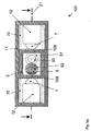
- Fig. 2a shows a schematic cross section through the switching valve 100 according to another embodiment.
- the fluid housing 5 which may for example be connected to the valve housing 11, there may be a switching element 6, which has the shape of a ball, and a first position element 93, which may be formed, for example, in the first position 91 as a pocket, and a second position member 94 which may be formed, for example, in the second position 92 as a sealing seat.
- the holding element 2 can be formed for example by one or more springs.
- the fluid housing 5 has in this embodiment at the location of the momentum transfer from the actuator 70 to the switching element 6, which may also be referred to as a transmitter 108, a special shape design, which may be formed as a membrane.
- Further elements of the fluid housing 5 may be a fluidic inlet 4 and a fluidic outlet 3.
- a driver element 8 For exerting the switching operation of the switching element 6, a driver element 8, a transducer element 12 and two contact elements 7 may be located in the valve housing 11, for example
- two energy storage 1 are shown, which may for example be designed as prestressable springs.
- the actuating device 70 may comprise, for example, a transducer element 12 and a contact element 7.
- the transducer element 12 may serve, for example, the conversion of energy from a provided energy source into a kinetic energy.
- the contact element 7 can serve to bring the contact element into contact with the fluid housing 5 in order to effect the pulse-like transmission of force to the switching element 6.
- the actuating device 70 may have a driver element 8.
- the driver element 8 can serve, for example, for transmitting the kinetic energy converted by the transducer element 12 to the contact element 7, wherein the driver element 8 can be connected to the contact element 7.
- the driver element 8 can also serve for fastening the actuating device 70 to the fluid housing 5 or to a valve housing 11 comprising the fluid housing 5 and the actuating device 70.
- the driver element 8 and the transducer element 12 form a unit.
- the energy storage 1 are not necessarily required for the function of the switching valve 100. It is conceivable that the energy storage 1 form a unit with either the transducer element 12 or the driver element 8.
- the driver element 8 can perform a rotational movement in this example.
- the contact elements 7 may be connected to the driver element 8 and together represent a mass with the driver element 8. It is conceivable that the contact elements 7 form a unit with the driver element 8.
- the driver element 8 can move over a certain angular range, without there being any contact between the contact elements 7 and the fluid housing 5 at the transmitter points 108.
- the transducer element 12 can receive energy from an electrical, piezoelectric, hydraulic or pneumatic energy source and generate a force in at least one of the rotational directions of the driver element 8.
- the driver element 8 may be coupled to the transducer element 12 so that the force of the transducer element 12 can lead to the driver element 8 to a rotational movement of the driver element 8 and the contact elements 7 in the corresponding direction of rotation.
- the driver element 8 may for example have a bearing 24 or a joint 15, wherein the kinetic energy of the transducer element 12 can be transmitted from a first lever arm 301 of the driver element 8 via a second lever arm 302 of the driver element 8 to the contact element 7.
- a common lever axis 300 of the first lever arm 301 and the second lever arm 302 may be defined by an axis of the bearing 24 or the hinge 15.
- the driver element 8 can be in an angular position between the two maximum possible angles of rotation of a rotational direction, which are given in this example by the transmitter 108 to the membranes.
- the transducer element 12 can be supplied with energy and drive at least the driver element 8 together with the contact elements 7, wherein a rotational movement arises, which can be designed so that in a first phase of rotation at least the driver element 8 and the Contact elements 7 can absorb kinetic energy and that in a further phase of the rotational movement, this kinetic energy in one Impact operation by one of the two contact elements 7 at least partially on one of the transmitter 108 on the diaphragm and the switching element 6 can be transmitted.
- the switching element 6 can then move from a first position 91 to a second position 92 or remain in said first position 91.
- the first position 91 and the second position 92 are determined by the design of the fluid housing 5 in the form of position elements 93, 94, which position the switching element 6 stable.
- the switching process can take place in various forms.
- the movement may be such that the contact element 7 is moved from the beginning of the movement directly to the impact towards the said transmitter 108 on the membrane.
- Another possibility is to make the movement so that the contact element 7 initially in the opposite direction, d. H. is then moved away from the transmitter to be contacted 108 on the membrane, whereupon at least one of the energy storage 1 receives energy, and the direction of movement is reversed at a certain angle of rotation of the driver 8 and the contact element 7 after reversing the said transmitter 108 at the Membrane moves too.
- the impact process in the energy transfer to the switching element 6 it is possible, for example, to generate an at least sufficiently large pulse on the switching element 6, so that the breakaway energy can be applied.
- the switching element 6 is in contact with the transmitter 108 to be contacted on the membrane before the impact or the transmitter 108 to be contacted can be deformed on the membrane with low energy consumption during the impact process until it comes into contact with the switching element 6 comes.
- the energy transfer can be most efficient, for example, when the impact is central and the effective mass of the moving parts, ie essentially the driver element 8 and the contact elements 7, about the same size as the mass of the switching element 6 to be moved.
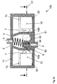
- Fig. 2b shows a schematic longitudinal section through the switching valve 100 according to the embodiment.
- the sectional plane 21 represents the plane through which the switching valve 100 according to Fig. 2a can be cut to the schematic longitudinal section according to Fig. 2b to obtain.
- the driver element 8 which in Fig. 2a has the shape of a stirrup, in Fig. 2b
- the fluid housing 5 has a membrane-like configuration at the transmitter points 108, ie at the points at which the pulse is transmitted from the actuating device 70 to the switching element 6.
- the driver element 8 can be accelerated by a trained as a spring element energy storage 1 to pitch with the contact element 7 on the diaphragm of the fluid housing 5 to deliver the pulse to the switching element 6, which can switch from a first position 91 to a second position 92.
- the switching element 6 is held in this embodiment by a holding element 2, which is designed as a spring in the first position 91 or in the second position 92, wherein the switching element 6 in the first position 91 a fluid path 3, 4 through the fluid housing. 5 can release (eg, "valve open") and in the second position 92 the fluid path 3, 4 can block through the fluid housing 5 (eg "valve closed").
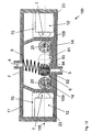
- Fig. 3a shows a schematic cross section through the switching valve 100 according to a further embodiment, which is substantially the embodiment according to Fig. 2a and 2 B characterized in that a drive unit with two transducer elements 12 and two driver elements 8 can be used.
- the driver element 8 has in this embodiment, a bearing 24, wherein each of the two driver elements 8 may have its own bearing 24.
- the driver element 8 With the transducer element 12, the driver element 8 can be deflected by means of a rotation about the axis of the bearing 24, in order to supply with the deflection a formed as a biasing spring energy storage 1 with the breakaway energy.
- the stored breakaway energy can be released from the energy store 1 in order to trigger the shock-like action of force on the fluid housing 5.
- the drive mechanism may be formed as an electromagnetic, electrostatic, piezoelectric, pneumatic, hydraulic drive or as a manual drive with mechanical translation.
- the prestressable spring can be pretensioned in the opposite direction of the impact force on the fluid housing 5.
- the transducer element 12 may also deliver the necessary pulse to the fluid housing 5 without the use of an energy storage device 1 and as a piezoelectric bending transducer, as a piezoelectric stack, as an electromagnetic drive, as an electrostatic drive, as a pneumatic drive, as a hydraulic drive or be designed as a manual drive with mechanical translation.
- the transducer element 12 does not need to be permanently powered.
- a power supply is necessary to move the switching element 6 from one of the two positions 91, 92 to the other of the two positions 91, 92. After taking the desired fluidic switching state, for example, the power supply can be decoupled from the transducer element 12.
- Fig. 3b shows a schematic longitudinal section through the switching valve 100 according to the embodiment.
- this longitudinal section is no difference to the embodiment according to Fig. 2b to recognize.
- the section does not show that the driver element 8 consists of two separate parts and is not formed as in the second embodiment as a single part. While in the embodiment according to Fig. 2a / b a single transducer element 12 the Energy conversion takes over, the energy conversion happens in the embodiment according to Fig. 3a / b with two transducer elements 12.
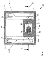
- Fig. 4a shows a schematic cross section through the switching valve 100 according to another embodiment.
- FIG. 4a FIG. 10 is a plan view cut at a section line 21 in FIG Fig. 4b
- the actuator 70 comprises a pulse generating unit which is selected as a piezo bending transducer.
- the piezoelectric bending transducer can represent both the transducer element 12 and the driver element 8, and be clamped at one end and carry the contact element 7 at the other end.
- the fluid housing 5 may be formed as a rigid wall in the area of the transmitter 109, which may be a part of the fluid housing 5, wherein the rigid wall is for example able to conduct pressure waves to the pulse from the actuator 70 to the switching element 6 to transfer.
- the pulse can be delivered to the rigid wall in the area of the transmitter 109.
- the piezoelectric bending transducer can be integrated, for example, in the driver element 8 or transducer element 12 in order to form a deformation when a voltage is applied, in order to accelerate the contact element 7 against the rigid wall 109 of the fluid housing 5. Due to the material properties of the rigid wall, upon impact of the contact element 7 with the transmitter 109, for example, a pressure wave is generated in the rigid wall 109 of the fluid housing 5. The occurring deformation happens abruptly, which allows an efficient impulse transfer.
- the driver element 8 is firmly clamped in this embodiment by means of a clamping 23 together with the transducer element 12 at a first end. At a second end of the driver element 8, which is connected to the contact element 7, the driver element 8 is movable to the kinetic energy at the second end to the contact element. 7 to transmit and deliver the pulse to the fluid housing 5.
- Fig. 4b shows a schematic longitudinal section through the switching valve 100 according to the embodiment.
- Fig. 4b represents the side view, cut at the section line 21 according to Fig. 4a ,
- FIG. 2 illustrates a schematic cross section through the switching valve 100 according to a further exemplary embodiment.
- Fig. 5a FIG. 12 is a plan view cut on the section line 21 in FIG Fig. 5b ,
- the representations of Fig. 5a / b are from the Fig. 4a / b derived.
- a piezo stack can be used as a transducer element 12, consequently, the dimensions of the valve housing 11 can be reduced.
- the driver elements 8 can be omitted if on both sides of the fluid housing 5 each have a transducer element 12 are mounted thereon with contact elements 7.
- an adapted clamping 23 can be provided.
- Fig. 5b shows a longitudinal section through the switching valve 100 according to the embodiment.
- Fig. 5b corresponds to the side view, cut at the section line 21 according to Fig. 5a
- the fluid housing 5 is formed in the region of the transmitter 109 as a rigid wall, so that the shock from the piezo stack of the transducer element 12 via the contact element 7 on the transmitter 109 of the fluid housing 5 and on to the switching element 6 can be transmitted.
- the clamping 23 of the transducer element 12 may be made smaller than in the figures shown above.
- Fig. 6 shows a schematic cross section through the switching valve 100 according to another embodiment.
- the principle of this arrangement is to use only a single transducer element 12, which, for example, by a special construction of the driver elements 8 on both transmitters 109 on the rigid wall simultaneously acts, so that each time the transducer element 12, the switching element 6 can be switched to the next position.
- the driver elements 8 can be fixed via solid joints 15. These may for example be attached to the fluid housing 5, but they may as well be attached to a suitable position on the valve housing 11.
- a force of the transducer element 12 on the driver element 8 can be transmitted via a first lever arm 301 to a second lever arm 302 to push the contact element 7 against the rigid wall 109 in the transmitter area against the fluid housing 5.
- the first lever arm 301 is formed, for example, by a force application point of the transducer element 12 on the driver element 8 and an axis 300 of the joint 15 or solid-state joint.
- the second lever arm 302 is formed, for example, by a force acting point of the contact element 7 on the fluid housing 5 and the axis 300 of the joint 15.
- Fig. 7 shows a cross section through the switching valve 100 according to another embodiment.
- the pulse generation can be done by first biasing the transducer element 12 against an energy storage device 1. Then, the driver element can be released, the energy storage 1 can accelerate the driver element 8 in the opposite direction, so that the driver element 8 can bounce on the transmitter 109 in the region of the rigid wall.
- This arrangement is also a good example that the transducer element 12 need not be a piezoelectric element, but z. B. may be an electromagnetic drive.
- the transducer element 12 can work, for example, for all body variants according to any drive principle, z. As electromagnetic, electrostatic, piezoelectric, pneumatic, hydraulic, etc. Similarly, a manual operation with mechanical translation is conceivable.
- a switching valve 100 can be realized, which is normally closed safely, that is, when the power fails, the valve 100 closes, if it is not already closed anyway.
- This aspect can be very important for certain applications, eg in automation technology, in order to be able to transfer a system to a safe state in the event of a power failure.
- actuating device 70 on the right side which is responsible for a switching operation, "closing" of the valve 100 is designed so that it is always biased in the energized state, for example by an electromagnet, the driver element 8 against the spring. 1 If the current fails, the actuating device 70 switches again because the electromagnet releases the pretensioned driver element 8 and, in the case of an open valve 100, it closes. In the case of an already closed valve 100, this remains closed.
- Fig. 8a shows a longitudinal section through a switching valve 100 according to another embodiment with the switching element 6 in a first position 91.
- the first position 91 corresponds to the open switching valve 100.
- the reason behind this arrangement is that due to manufacturing tolerances in For example, the arrangements shown before are not guaranteed can be that the switching element 6 can simultaneously abut the transmitter 109 of the rigid wall and the fluidic outlet 3 can seal tight.
- the first requirement may be essential for the proper operation of the switching valve 100.
- the sealing function of the switching element 6 can be decoupled from the abutment function on the transmitter 109 of the rigid wall by the switching element 6 is rigidly connected to a pulse pickup 16 and can be rotatably mounted about a rotation axis of a rotary member 19.
- the pulse transmitted by the contact element 7 can be picked up by the pulse pickup 16, for example, to accelerate the pickup 16 to the right and thereby the switching element 6, which can be coupled to the pickup 16 via a rigid connecting element 17, in such a way that the flow of the fluid through a bore 18 in the switching element 6 and the adjoining fluidic outlet 3 is interrupted.
- the opening operation can be carried out analogously by an actuation, for example, of the right-hand converter element 12.
- Fig. 8b shows a longitudinal section through the switching valve with the switching element 6 in a second position 92 according to the embodiment.
- the rotation of the switching element 6 from the first position 91 to the second position 92, the fluid flow along the fluid path 3, 4 is interrupted, since the bore 18 is no longer arranged in this embodiment, that the fluid can flow through them.
- the switching element 6 may comprise in this embodiment, a pulse pickup 16, a rotary member 19 having a bore 18 and a rigid connecting member 17 for rigidly connecting the pulse pickup 16 to the rotary member 19.
- the pickup 16 may be formed to receive a pulse of the jerky force acting on the fluid housing 5 and to transmit the pulse via the rigid connecting element 17 to the rotary member 19.
- the rotation member 19 may be configured to transform the pulse into a rotational movement to move the switching element 6 from one (91) of the two positions 91, 92 to the other (92) of the two positions 91, 92, and the rotation element 19 may be configured to in the first position 91, the fluid path 3, 4 by the fluid housing 5 while flowing through the bore 18 unlock (eg, "switching valve open"), and in the second position 92 due to the rotation of the bore 18 with the rotary member 19 to block the fluid path 3, 4 through the fluid housing 5 (eg, "switching valve closed”) .
- the pulse pickup 16 may be configured to assume two positions 91, 92 associated with the two positions 91, 92 of the switching element 6.
- the seal tolerance of the switching element 6 can be realized for example by means of the rotary member 19 and the application tolerance of the switching element 6 can be realized for example by means of the pulse pickup 16 Thus, the two manufacturing tolerances can be decoupled from each other to simplify the manufacture of the switching element 6.
- Fig. 9a shows a longitudinal section through the switching valve 100 according to another embodiment.
- Fig. 9a shows the side view, cut at the section line 21 according to Fig. 9b .
- the manufacturing tolerances for example, can not guarantee simultaneous installation on the transmitter 109 and a simultaneous sealing function. Therefore, with two springs 28, 29, the switching element 6 can be positioned in the first position 91 and in the second position 92.
- the holding element 2 according to Fig. 1 may comprise two springs in this embodiment, for example, a first spring 28 for fixing the switching element 6 at an upper end within the fluid housing 5 and a second spring 29 for fastening the switching element 6 at a lower end within the fluid housing fifth
- the first spring 28 and the second spring 29 are arranged, for example, within the fluid housing 5 so that the switching element 6 can move from one of the two positions 91, 92 into the other of the two positions 91, 92 while applying the breakaway energy and during this movement can be held by the two springs 28, 29 of the retaining element 2.
- the two springs 28, 29 may be designed such that they each have a maximum possible spring deflection in the first position 91 and in the second position 92, without leaving an elastic region of the springs 28, 29 in order to form the potential wall, which prevents the switching element 6 from changing without external action of energy from one of the two positions 91, 92 to the other of the two positions 91, 92.
- the switching element 6 can absorb a kinetic energy that allows the switching element 6, under contraction of the two springs 28, 29 and overcoming other forces, such as friction forces and flow forces to change from the second position 92 to the first position 91 or vice versa.
- the switching element 6 is designed, for example, to release a first fluid path 31, 4 through the fluid housing 5 in the first position 91 and to block a second fluid path 32, 4 through the fluid housing 5, wherein the second fluid path 32, 4 of FIG the first fluid path 31, 4 different.
- the switching element 6 may be configured to release the second fluid path 32, 4 through the fluid housing 5 and to block the first fluid path 31, 4 through the fluid housing 5.
- the seal tolerance and the fitting tolerance are to be referred to the same surface of the switching element 6, since at the same location, for example, the pulse can be transmitted and one of the fluid paths 31, 4 or 32, 4 can be sealed or locked.
- the two fluidic outlets 31, 32 are arranged.
- the impulse transmission can thus be transmitted via an annular surface, for example, on which the switching element 6 bears against the fluid housing 5 in the transmitter region 109.
- an impulse transmission could ideally be done over a single point, for example as a Hertz cal pressure, namely in the event that the globally configured switching element 6 at a point on the wall of the fluid housing 5 was applied.
- the fluidic outlet 31, 32 may, for example, have a round opening, wherein the center of the circle of the opening may lie on the actuation axis 105, in order to ensure the most central pulse propagation from the fluid housing 5 to the switching element 6.
- Fig. 9a shows by way of example that multi-way valves, ie valves with more than one fluidic inlet and outlet, can also be realized with this functional principle.
- a 3/2-way valve is shown with a fluidic inlet 4 and two fluidic outlets 31 and 32, which can be opened alternately.
- Generalized can be realized with any number of inlets and outlets by appropriate arrangement of possibly more switching elements 6 and correspondingly positioned transducer elements 12 switching valves 100.
- Fig. 9b shows a schematic cross section through the switching valve 100 according to the embodiment.
- Fig. 9b illustrates the top view, cut at the section line 21 according to Fig. 9a ,
- the two fluidic outlets 31, 32 can be seen and a spring 28 of the holding element 2.
- the second spring 29 can be located above the cutting plane due to the sectional view, so that it is not visible in this sectional view.
- the actuating device For example, 70 may have a clamping 23 to clamp the transducer element 12, the driver element 8 and the contact element 7 at an upper end.
- the transducer element 12 may for example be designed as a piezoelectric bending transducer, so as to perform a shock-like movement due to a change in length of the driver element 8 on the contact element 7 in order to transmit the shock in the region of the transmitter 109 of the fluid housing 5 to the switching element 6.
- both transducer elements 12 are supplied with energy, so that both contact elements 7 encounter the fluid housing 5 in the region of the transmitter 109.
- the pulse can then be transmitted, for example, at both transmitter points 109 via the fluid housing 5, but only at a transmitter point 109 impinges on the switching element 6, which bears against the inner wall of the fluid housing 5 in the region of the corresponding transmitter point 109.
- the second pulse transmission for example, no switching element 6 before, so that the second pulse can travel through the fluid housing 5 and can be damped by the fluid housing 5.
- a simultaneous actuation of the two transducer elements 12 can therefore not be considered energy efficient, but has the advantage that no information is necessary for the triggering of the switching process, in which of the two positions 91, 92, the switching element 6 is currently.
- the switching valve 100 always sets the state for which the switching operation is triggered. For example, an activation of a state “to” or “close valve” always leads to a closed valve 100 and a control of a state “open” or “open valve” always to an open valve 100th
- Fig. 10 shows a schematic longitudinal section through the switching valve 100 according to another embodiment.
- the sealing element 13 for example, the manufacture of the switching element 6 can be simplified, since an inaccurate seal tolerance can be compensated by the sealing element 13.
- the sealing element 13 may be designed as a ring made of plastic in order to seal a ball-shaped switching element 6 against the fluid housing 5.
- the sealing element 13 can also simplify production of the switching element 6, since, for example, it is no longer necessary at the same time to maintain two tolerances at two different points, but the sealing tolerance is effected by the sealing element 13 and the contact tolerance is effected by the switching element 6.
- Fig. 11 shows a schematic longitudinal section through the switching valve 100 according to another embodiment.
- the impulse transmission from the contact element 7 to the switching element 6 can be effected, for example, by a transmitter 108, whereby the media separation can be realized by this transmission mechanism, ie, the fluid in the switching valve 100 has no contact with any elements of the pulse generating transducer element 12, but only for example, the inner sides of the fluid housing 5 and, for example, the switching element.
- 6 Fig. 11 shows an example in which the transmitter 108 is not identical to the fluid housing 5, but may be designed as a separate component, which may be tightly connected to the fluid housing 5, so that no fluid can escape.
- the transmitter 108 of a different material as the fluid housing 5, for example of an elastic material, which can compensate for any manufacturing tolerances easier.
- the switching element 6 it may be sufficient for the switching element 6 to comply with a seal tolerance and comply with less restrictive requirements in the field of a placement tolerance.
- Fig. 12 shows a schematic longitudinal section through the switching valve 100 according to another embodiment.
- the pulse generated by the transducer element 12 can be transmitted for example by the contact element 7 via the transmitter 109 to an intermediate element 14, which is designed spherical, but may also be configured, for example, cylindrical or may have another shape.
- This intermediate element 14 can then be accelerated, for example, in the direction of the switching element 6 be to deliver its kinetic energy to the switching element 6, whereby the change of the switching element 6 can be triggered by a first position 91 to a second position 92 or vice versa.
- the safe operation of this principle can be achieved for example by a return spring 20, which can cause the system of the intermediate element 14 to the transmitter 109 in a resting state. It would also be conceivable, for example, to use a magnetic return mechanism for the intermediate element 14 instead of the return spring 20.
- the fluid housing 5 may be configured to impart momentum transfer from the actuator 70 via one of the two intermediate elements 14 using the two intermediate elements 14, which are ideally located on the actuation axis 105 within the fluid housing 5 and movable on this actuation axis 105 cause the switching element 6 to move the switching element 6 of one of the two positions 91, 92 in the other of the two positions 91, 92.
- the fluid housing 5 may be formed, for example, to retrieve the two intermediate elements 14 using a return spring 20 in their rest positions, the two intermediate elements 14 abut taking their resting positions, for example, on two opposite inner walls of the fluid housing 5 in order to effect the momentum transfer can.
- the contact tolerance of the switching element 6 can be increased, that is, a production of the switching element 6 can be simplified in that the landing need not be performed as accurate as, for example, in the embodiment according to Fig. 1 would be necessary.
- Fig. 13 1 shows an illustration of a method 200 for switching a switching valve 100.
- the method 200 may comprise, for example, a first step 201, in which First step 201 is applied a shock-like force to the fluid housing 5 with the actuator 70 to cause a pulse-like power transmission to the switching element 6 to move the switching element 6 from a first position 91 to a second position 92, wherein the switching element 6 in the first position 91 defines a first fluidic state of a fluid path 3, 4 through the fluid housing 5 and wherein the switching element 6 in the second position 92 defines a second fluidic state of a fluid path 3, 4 through the fluid housing 5, which is different from the first fluidic state different.
- the method 200 may be performed by the first step 201, wherein the first step 201 describes, for example, a switching operation of the switching valve 100.
- the first step 201 can be executed again.
- the first step 201 for switching multi-way switching valves can be executed once or several times in succession.
- Fig. 14 shows a schematic representation of a cross section through a multiple switching valve 300 according to an embodiment.
- the multiple switching valve 300 has in this embodiment, four locking positions in which the switching element 6, the positions 92, 91a, b, c can take stable.
- the actuating device 70 which is mounted outside of the fluid housing 5, in this exemplary embodiment has eight combinations with contact elements 7, driver elements 8 and transducer elements 12.
- the switching element 6, each of the four positions 92, 91 a, b, c take.
- simultaneous or approximately simultaneous control of two transducer elements 12 it is for example also possible to bring the switching element 6 in an opposite position, for example, from the position 92 in the position 91b.
- a multi-way valve can be realized, e.g. a mixing valve, which can cause a mixing of several fluids according to a predetermined mixing ratio.
- the multiple switching valve 300 may also be operated with more than one switching element 6, for example, with two switching elements 6 according to Fig. 14 .
- Both switching elements 6 fixed positions 91, 92a, b, c can be assigned, for example, the positions 92 and 91a for a first switching element 6 and the positions 91b and 91c for a second switching element 6.
- the switching elements 6 below Taking each of the positions 92, 91 a, b, c to move within the fluid housing 5, for example, in response to a control of the transducer elements 12th
- a switching valve 100 may have, for example, as a first functional feature or as a first functional variant, that a switchover is realized by shock actuation, as shown in FIG Fig. 4a / B.
- a second functional feature may be the latching positions of the switching element 6 defined by the position elements 93, 94, and also in FIG Fig. 4a / b are shown.
- a third feature may be the potential barrier existing between the two positions 91, 92. Also the potential wall is in Fig. 4a / b.
- the valve inlet 4 and the valve outlet 3, which are also shown in FIG Fig. 4a / b are shown.
- the pulse can be generated, for example, by a piezo bending transducer, as shown in the Fig. 4a / b, 8a / b, 9a / b and 11.
- the pulse generation can be carried out by a piezo stack, as shown in the Fig. 5a / b, 10 and 11.
- the pulse generation can be effected by a piezo stack with deflection mechanism, which is fixed by a solid-state joint 15, as shown in the Fig.
- the pulse generation can be effected by a bias of the driver element 8 against an energy storage 1 and momentum transfer when swinging back, as shown in the Fig. 7 ,
- the pulse generation can by an electromagnetic drive, for example according to Fig. 7 , or by a hydraulic drive, an electrostatic drive, a pneumatic drive or by a manual actuator 70 with mechanical translation.
- FIG. 1 Another partial aspect of the switching valve 100, for example, the realization of the switching positions by the position elements 93, 94 and the positions 91, 92.
- the holding element 2 the switching element 6 in the position element 93, 94 press, which the first position 91 and second position 92 forms.
- the pickup 16 can rotate a rigidly connected switching element 6, which in Fig. 8a / b is shown.
- the switching positions 91, 92 can be realized by two opposing holding elements 2, which is exemplified in Fig. 9a / b is shown.
- Another aspect of the switching valve 100 may be the impulse transmission, which may for example be done on a rigid wall, ie the transmitter 109 may be part of the fluid housing 5. This is shown in the example Fig. 4a / b, 5a / b, 6, 7, 8a / b, 9a / b and 10.
- the impulse transmission can be done on a flexible membrane, which is for example in Fig. 11 is shown.
- the impulse transmission can also take place on a rigid wall with spring-suspended intermediate body 14, which is exemplified in FIG Fig. 12 is shown.
- Another aspect of the switching valve 100 may be the operation of the seal. This can be done for example with an elastic insert element or a sealing element 13, which, for example, in Fig. 10 is shown.
- Switching valves 100 are needed in many applications, where it matters, one of two fluidic states 91, 92, hereinafter called switching states or positions, z. B. two switching states 91, 92 with different fluidic resistances, to drive and then maintain this state without further energy consumption. This applies, for example, to automation technology, including pneumatics, as well as process technology, automotive technology or medical technology. If toxic, aggressive or sensitive fluids, such as chemicals, fuels or body fluids are to be controlled, then a good sealing function in the switching valve or valve 100 must be ensured. Further, for reasons of safety or compatibility, media separation may be required. Contact with the fluid can cause problems, among other things, with important components of the drive, such as electronic assemblies, resistors, coils or bending transducers.
- the valve 100 is designed so that in the region of the valve 100 that is filled with fluid or that is contacted by the fluid, only elements of the valve 100 that are compatible with the fluid are located.
- these in addition to a fluid housing or fluidic housing 5, these are at least one controllable switching element or fluidic switching element 6, at least two position elements 93, 94 and at least one retaining element 2.
- the fluidic housing 5 essentially constitutes that part of the valve 100, which comes into contact with the fluid in which the fluid is guided and where the different fluidic resistances corresponding to the switching states 91, 92 can be realized.
- the fluidic switching element 6 causes by its geometric position in the fluidic housing 5, the expression of the two switching states 91, 92.
- the position elements 93, 94 serve at least each for spatial positioning of the fluidic switching element 6 in each one of the two switching states 91, 92. They are such that in each of the switching states 91, 92 results in a different fluidic state, for example, a different flow with different fluidic resistance.
- the position elements 93, 94 consist at least of a seat in which the fluidic switching element 6 is positioned in a switching state 91, 92 at least in cooperation with the holding element 2 so that the desired fluidic resistance arises.
- the holding element 2 has inter alia the task of ensuring that a sufficient force acts on the fluidic switching element 6 when the fluidic switching element 6 is positioned in a position element 93, 94, and that the potential energy of the fluidic switching element 6 in each of the positions defined by the position elements 93, 94 at a minimum and the potential energy of the fluidic switching element 6 at any other location is at least greater than the minimum potential energy in one of the positions 91, 92 defined by the position elements 93, 94.
- the fluidic switching element 6, the holding element 2 and the position elements 93, 94 are created so that the fluidic switching element 6 is usually in one of the positions 91, 92 except during the switching operations.
- the fluidic switching element 6 can be suitably supplied with at least so much energy or such a force can be exerted to allow it to leave the potential barrier and other forces leaving the fluidic switching element 6 Position 91, 92 prevent, such as friction forces or overcome forces generated by the fluid.
- the force for overcoming said other forces is called breakaway force below.
- the fluidic switching element 6 is designed according to the invention as a ball and the two position elements 93, 94 as depressions.
- the retaining element 2 can then consist of a spring, for example.
- suitable slides, flaps, pistons or lids are conceivable as fluidic switching element 6, depending on requirements.
- the fluidic housing 5 has except the required fluidic inlet 4 and outlets 3 at most such further penetrations that can not be permanently passed by the fluid and through which, however, the drive energy can be introduced.
- the valve housing 11 z. B. are made of only a single material or of different materials, wherein a plurality of housing parts, for example, cohesively or non-positively tightly connected to each other. In this type of media separation, the introduction of the energy required for the switching operations often represents a technical problem, for which there may be various solutions, which are exemplified here.
- the energy can be supplied by a magnetic field, wherein the field lines can pass a fluidically impermeable housing made of suitable non-magnetic materials without substantial impairment.
- Another possibility of energy transfer is to utilize the inertia of the mass of the fluidic switching element 6 of the valve 100 in order to transfer the fluidic switching element 6 from one switching state 91 into the other 92.
- Such an energy transfer is known from acceleration sensors, such as those used in the car for triggering the airbag. Since at least the entire fluidic housing 5 can be accelerated, this results in addition the unfavorable movement of the fluidic housing 5 a worse energy balance.
- Another example is a mechanical drive, in which the energy is applied to the fluidic switching element 6 of the valve 100 by a comparatively slowly variable force, which acts practically for the entire duration of the switching operation over a certain distance, as z. B. can be realized via a tight bellows.
- Another possibility of the mechanical drive is that the energy to the switching element or fluidic element 6 in a comparatively short period of time, which is shorter than the time required for the switching operation of the fluidic switching element 6 from one 91 in the other switching state 92 , is transmitted.
- This can be done with a kind of impact process by at least one suitable transmitter 108, 109, which has the task to transfer the necessary energy mechanically from a source outside the fluidic housing 5 to the fluidic switching element 6 in the interior of the fluidic housing 5.
- the transmitter 108 may, for. B.
- the period of deformation of the transmitter 108 for the purpose of energy transmission by the impact process is shorter than the time that during the switching operation of the fluidic switching element. 6 , d. H. the movement from one 91 to the other position 92, passes.
- the fluidic switching element 6 receives so much kinetic energy that it can apply the breakaway force and overcome the potential barrier.
- the force acting on the switching element 6 is greatest when it is needed, namely at the very beginning of the movement when the breakaway force is applied so that anything moves at all.
- this breakaway force is overcome, for example the stiction, etc., no longer needs so much energy to be supplied to maintain the movement in the other detent position.
- the time profile of the force just required for moving the switching element 6 from one position to the other 91, 92 may be referred to, for example, as an ideal force characteristic of the switching element 6.
- the force characteristic that can be generated with the pulse-like drive or the actuating element 70 now comes very close to this ideal force characteristic, which brings advantages in terms of energy efficiency.
- the effect of the transmitter 108, 109 can be very well illustrated with the physical pendulum experiment, where, for example, five equal elastic balls, z. B. K1 - K5, are suspended in a horizontal line by means of vertical threads. If one of the outer balls, z. B. K1, deflected and hits when returning to the now outermost of the resting balls, z. B. K2, it gives its energy to the other first outer sphere, d. H. K5, where the balls K2, K3 and K4 remain practically at rest. In this case, the balls K2, K3 and K4 have performed virtually no movement, but experienced only necessary for transmitting the energy deformations. This last option is referred to below as a push operation. In this case, the mechanical energy that is required for the impact operation, generated by a transducer element 12.
- valve 100 For a number of valves, energy consumption is critical and must be minimized. Consider, for example, telemetrically controlled valves in hard-to-reach places in machines. Therefore, it is important, first, to ensure that the valve 100 receives energy only during the switching operation from one switching state 91 to the other switching state 92 and consumed no energy at all between the switching operations.
- the definition of the switching state 91, 92 is carried out by the fluidic switching element 6 with the cooperation of at least one holding element 2 and for example the position elements 93, 94.
- the fluidic switching element 6 can be moved in the switching operation from a first position 91 to a second position 92, wherein the fluidic State, for example, the fluidic resistance of the fluid through the valve 100 in one of the positions 91 is different to the fluid state in the other position 92.
- the maintenance of the switching state 91, 92 can be effected by the holding member 2, wherein the potential energy of the fluidic switching element 6 for each of the two switching states 91, 92 may assume a minimum and between the positions 91, 92 of the fluidic switching element 6 may be a Potentialwall.
- a ball by means of the holding element 2, which may be a spring, as shown in the selected embodiment, also a magnetic latching can be performed, for example, at least one permanent magnet is used. Due to the expression of the fluidic switching element 6, the support member 2 and the position elements 93, 94 in particular the Verarrungshunt in the two positions 91, 92, z. B. in shocks, energy consumption and fluidic properties are affected.
- valves 100 which control a liquid
- the movement of the fluidic switching element 6 can be damped by the viscosity of the liquid, which can influence the energy consumption per switching operation.
- the damping can also be used advantageously to improve the dynamic behavior of the fluidic switching element 6, z. B. to minimize the influence of transient effects, whereby a safe ingestion of the position elements 93, 94 predetermined positions 91, 92 achieved becomes.
- the fluidic switching element 6 is prevented from leaving the respective position 91, 92 by frictional and adhesive forces as well as by forces which the fluid exerts.
- Embodiments of the present invention include various types of valves 100 having a push-action drive and media separation in the sense described above. This means that the actual transducer elements 12 of the valve 100, which generate the kinetic energy or the forces necessary for the switching process by conversion from an electrical or pneumatic energy source, are located outside the fluidic housing 5 of the valve 100.
- Electromagnetic drives, piezoelectric bending transducers, piezoelectric stack converters or pneumatic drives can be used as transducer elements 12.
- transducer elements 12 and the electronic circuits for providing the need for the drive electrical voltages or currents will not be discussed here, since these are basically known in the prior art.
- FIG. 2a / b An embodiment of the switching valve 100 with impact operation is in Fig. 2a / b.
- the fluidic housing 5 which is connected to the valve housing 11, there is a fluidic switching element 6 in the form of a ball and a first position element 93 in the first position 91 as a pocket and a second position element 94 in the second position 92 as a sealing seat.
- the holding element 2 is formed by a spring.
- the two transmitters 108 are each formed by a membrane as part of the fluidic housing 5.
- Further elements of the fluidic housing 5 are the fluidic inlet 4 and the fluidic outlet 3.
- a driver element or driver 8 For carrying out the switching operation of the fluidic switching element 6 are in the valve housing 11, a driver element or driver 8, a transducer element 12 and two contact elements 7. Furthermore, two energy storage.
- the driver 8 and the transducer element 12 form a unit.
- the energy storage 1 are not necessarily required for the function of the valve 100. It is conceivable that the energy storage 1 form a unit with either the transducer element 12 or the driver 8.
- the driver 8 can perform a rotary motion in this example.
- the contact elements 7 are connected to the driver 8 and together with the driver 8 is a mass.
- the contact elements 7 form a unit with the driver 8.
- the driver 8 can move over a certain angular range, without there being any contact between the contact elements 7 and the transmitters 108.
- the transducer element 12 may receive energy from an electrical or pneumatic energy source and generate a force in at least one of the directions of rotational movement of the driver 8.
- the driver 8 is coupled to the transducer element 12 so that the force of the transducer element 12 leads to a rotational movement of the driver 8 and the contact elements 7 in the corresponding direction of rotation.
- the driver 8 In the idle state, ie between two switching operations, the driver 8 is in an angular position between the two maximum possible angles of rotation of a rotational direction, which may be given by the transmitter 108 in this example.
- the transducer element 12 is supplied with energy and drives at least the driver 8 together with the contact elements 7, wherein a rotational movement is formed which is such that in a first phase of the rotational movement of at least the driver 8 and the contact elements 7 absorb kinetic energy and that in a further phase of the rotational movement, this kinetic energy in a collision process by one of the two contact elements 7 at least partially transmitted to one of the transmitter 108 and the fluidic switching element 6.
- the fluidic switching element 6 then moves from a first 91 of the position defined by the position element 93 into the other 92 of the position defined by the position element 94 or remains in the said first position 91.
- the switching process can take place in various forms.
- the movement may be such that the contact element 7 is moved from the beginning of the movement directly to the impact toward the said transmitter 108.
- Another possibility is to make the movement so that the contact element 7 initially in the opposite direction, d. H. away from the transmitter 108 to be contacted, whereupon at least one of the energy accumulators 1 receives energy, and the direction of movement is reversed at a certain angle of rotation of the driver 8 and the contact element 7 moves towards the transmitter 108 after the reversal.
- the fluidic switching element 6 is in contact with the transmitter 108 to be contacted before the impact or the transmitter 108 to be contacted is low in energy consumption deform during the impact process until it comes into contact with the fluidic switching element 6.
- the energy transfer is most efficient when the impact is central and the effective mass of the moving parts, i. H. essentially the driver 8 and the contact elements 7, approximately the same size as the mass of the fluidic switching element 6 to be moved.
- a further embodiment which is essentially the embodiment in Fig. 2a differs in that a drive unit with two transducer elements 12 and two drivers 8 is used.
- Another embodiment of the switching valve 100 according to the invention relates to a switching valve 100 with shock actuation and media separation, which can take two different switching states 91, 92.
- the further embodiment corresponding switching valve 100 consists of at least one valve housing 11 made of suitable materials, eg. As plastic, metal, glass or ceramic.
- the further embodiment corresponding switching valve 100 consists of at least one fluidic housing 5 as part of the valve 100, which consists of at least two parts of suitable materials, for.
- suitable materials for.
- plastic, metal, glass or ceramic consists, wherein the parts of the fluidic housing 5 consist of only a single material or of different materials and various parts are fluidly sealed together, and wherein at least a part of the fluidic housing 5 is a fluidic inlet 4 and another part of the fluidic housing 5 form a fluidic outlet 3, and wherein at least one transmitter 108 as part of the fluidic housing 5 or as an elastically deformable region of at least a portion of the fluidic housing 5, and wherein the fluidic housing 5 in the area filled with fluid includes at least two position elements 93, 94 according to the positions 91 and 92 for a fluidic switching element 6.
- the switching valve 100 corresponding to the further exemplary embodiment consists at least of a holding element 2 for holding a fluidic switching element 6 located in the area of the fluidic housing 5 filled with fluid.
- the switching valve 100 corresponding to the further exemplary embodiment consists of at least one fluidic switching element 6 located in the fluid-filled region of the fluidic housing 5, made of a suitable material, for.
- a suitable material for.
- the fluidic switching element 6, the holding element 2 and the position elements 93, 94 for the fluidic resistances of the valve 100 in the two switching states 91, 92 are relevant and wherein the fluidic switching element 6 in the period the switching operation of the valve 100 in a position other than one of the positions 91, 92 defined by the position elements 93, 94, and wherein the fluidic switching element 6 outside of the period of the switching operation of the valve 100 in exactly one of the position elements 93, 94 defined positions 91, 92, and wherein the potential energy of the fluidic switching element 6 for each of the positions defined by the position elements 93, 94 positions 91, 92 assumes a minimum and the potential energy of the fluidic switching element 6 in any position other than those 91, 92 , which are defined by the position elements
- the switching valve 100 corresponding to the further exemplary embodiment comprises at least one controllable drive unit located outside the fluid-filled region of the fluidic housing 5, comprising at least one transducer element 12, at least one movable driver 8 and at least one contact element 7, and optionally either at least one energy storage device 1 or no energy storage device 1, wherein the transducer element 12 and the driver 8 are coupled, and wherein either the transducer element 12 and the driver element 8 form a unit or wherein the transducer element 12 and the driver element 8 do not form a unit, and wherein either the energy storage device 1 and the transducer element 12 form a unit or wherein the energy storage device 1 and the transducer element 12 do not form a unit, and wherein the energy storage device 1 and the driver element 8 form a unit or wherein the energy store.
- the driver element 8 do not form a unit, and wherein at least one of the contact elements 7 with the driver element 8 is suitably coupled, and wherein each of the contact elements 7 taken alone with one of the driver 8 is a unit or none of the driver 8 is a unit forms, and at least the Mitne 8 and the contact elements 7 constitute a mass, and wherein the driver 8 can move in at least two directions along an axis or in at least two directions in a rotational movement, and wherein the supply of the transducer element 12 with energy causes the transducer element 12th drives at least the driver 8 together with at least one of the contact elements 7, wherein a movement is formed which is designed so that in a first phase of movement at least the driver 8 and at least one of the contact elements 7 receive kinetic energy and that in a further phase of the Movement, the kinetic energy in a collision process by at least one of the contact elements 7 at least partially transmitted to one of the transmitters 108, 109 and the fluidic switching element 6, wherein the fluidic switching element 6 of a first
Landscapes
- Engineering & Computer Science (AREA)
- General Engineering & Computer Science (AREA)
- Mechanical Engineering (AREA)
- Multiple-Way Valves (AREA)
- Fluid-Driven Valves (AREA)
- Lift Valve (AREA)
- Sliding Valves (AREA)
- Electrically Driven Valve-Operating Means (AREA)
- Magnetically Actuated Valves (AREA)
Abstract
Description
Ausführungsbeispiele der vorliegenden Erfindung betreffen ein Schaltventil und ein Verfahren zum Schalten eines Schaltventils.Embodiments of the present invention relate to a switching valve and a method for switching a switching valve.
Schaltventile werden in vielen Anwendungen benötigt, die darauf ausgerichtet sind, den Durchfluss eines Fluids an- oder auszuschalten bzw. von einem Durchflussweg auf einen anderen Durchflussweg umzuschalten. Beispielsweise betrifft dies Anwendungen in der Automatisierungstechnik, der Pneumatik, der Prozesstechnik, der Automobiltechnik oder der Medizintechnik. Bei Anwendungen mit giftigen, aggressiven oder empfindlichen Fluiden, beispielsweise Chemikalien, Kraftstoffen oder Körperflüssigkeiten, kann die Lebensdauer des Schaltventils von einer guten Dichtfunktion der Fluidwege im Ventil abhängig sein. Eine Berührung von beispielsweise elektronischen Baugruppen, Widerständen, Spulen oder Biegewandlern mit dem Fluid kann zu Problemen führen, welche die Lebensdauer des Ventils verkürzen können. Diese Probleme können auch im Bereich der Biokompatibilität bestehen. Elektrische Baugruppen können beispielsweise Materialien enthalten, die nicht biokompatibel sind. Für eine Anwendung, bei der durch das Ventil beispielsweise Körperflüssigkeiten geschaltet werden sollen, ist es jedoch sehr wichtig, dass diese nur mit biokompatiblen Materialien in Berührung kommen. Im Rahmen eines medizinischen Zulassungsverfahrens kann es insbesondere vor dem Hintergrund der Biokompatibilität zu Problemen kommen, wenn das Fluid in Kontakt mit nicht biokompatiblen Materialien kommen kann. Günstigerweise ist das Ventil so ausgeführt, dass sich in dem Bereich des Ventils, der mit Fluid gefüllt ist oder der von dem Fluid berührt wird, nur solche Elemente des Ventils befinden, die gegenüber dem Fluid unempfindlich sind.Switch valves are needed in many applications that are designed to turn fluid flow on or off, or to switch from one flow path to another flow path. For example, this relates to applications in automation technology, pneumatics, process technology, automotive engineering or medical technology. In applications involving toxic, aggressive or sensitive fluids, such as chemicals, fuels or body fluids, the life of the switching valve may depend on a good sealing function of the fluid paths in the valve. Contact with, for example, electronic assemblies, resistors, coils or flexural transducers with the fluid can lead to problems that can shorten the life of the valve. These problems can also exist in the area of biocompatibility. Electrical assemblies may include, for example, materials that are not biocompatible. However, for an application in which the valve is designed to switch bodily fluids, for example, it is very important that they only come into contact with biocompatible materials. In the context of a medical approval process, problems may arise in particular in the context of biocompatibility if the fluid can come into contact with non-biocompatible materials. Conveniently, the valve is designed so that in the region of the valve, which is filled with fluid or that of the fluid is touched, only those elements of the valve are located, which are insensitive to the fluid.
Bei bekannten Ventilen wird beispielsweise ein federbelasteter Bolzen gegen einen Ventilsitz gepresst, wobei der Bolzen zum Öffnen des Ventils mit Hilfe eines Elektromagneten vom Ventilsitz abgehoben werden kann.In known valves, for example, a spring-loaded bolt is pressed against a valve seat, wherein the bolt can be lifted to open the valve by means of an electromagnet from the valve seat.
Das Patent
Aus
Aus
Die Aufgabe der vorliegenden Erfindung besteht darin, ein verschleißarmes Ventil zu schaffen.The object of the present invention is to provide a low-wear valve.
Die vorliegende Aufgabe wird durch ein Schaltventil mit einem Fluidgehäuse, mindestens einem Schaltelement innerhalb des Fluidgehäuses und einer Betätigungseinrichtung außerhalb des Fluidgehäuses gemäß Anspruch 1 oder ein Verfahren zum Schalten eines Schaltventils gemäß Anspruch 15 gelöst.The present object is achieved by a switching valve having a fluid housing, at least one switching element within the fluid housing and an actuator outside the fluid housing according to
Aufgrund der Konstruktion des Schaltventils, bei dem das Schaltelement innerhalb des Fluidgehäuses und die Betätigungseinrichtung außerhalb des Fluidgehäuses angebracht sind, kann das Schaltventil verschleißarm arbeiten, da die Betätigungseinrichtung, die beispielsweise empfindliche elektronische oder mechanische Komponenten aufweisen kann, nicht mit dem möglicherweise aggressiven Fluid in Berührung kommt.Due to the construction of the switching valve in which the switching element within the fluid housing and the actuator are mounted outside the fluid housing, the switching valve can work wear, since the actuator, which may have, for example, sensitive electronic or mechanical components, not in contact with the possibly aggressive fluid comes.
Das Schaltventil umfasst ein Betätigungseinrichtung, die ausgebildet ist, um mittels einer stoßartigen Krafteinwirkung auf das Fluidgehäuse eine impulsartige Kraftübertragung auf das Schaltelement zu bewirken, um das Schaltelement von einer ersten Stellung in eine zweite Stellung zu bewegen, wobei das Schaltelement in der ersten Stellung einen ersten fluidischen Zustand eines Fluidwegs durch das Fluidgehäuse festlegt und wobei das Schaltelement in der zweiten Stellung einen zweiten fluidischen Zustand eines Fluidwegs durch das Fluidgehäuse festlegt, der sich von dem ersten fluidischen Zustand unterscheidet.The switching valve comprises an actuating device which is designed to effect a pulse-like force transmission to the switching element by means of a shock-like force acting on the fluid housing in order to move the switching element from a first position to a second position, wherein the Switching element in the first position defines a first fluidic state of a fluid path through the fluid housing and wherein the switching element in the second position defines a second fluidic state of a fluid path through the fluid housing, which differs from the first fluidic state.
Ein Kerngedanke der Erfindung besteht darin, eine stoßartige Krafteinwirkung der Betätigungseinrichtung auf das Schaltelement mittels Impulsübertragung über die Fluidgehäusewand zu übertragen, um eine räumliche Trennung von Schaltelement und Betätigungseinrichtung zu erlauben, so dass die Betätigungseinrichtung nicht gegenüber aggressiven Fluiden geschützt werden braucht. Eine Trennung der Betätigungsfunktion des Schaltventils von der Schaltfunktion des Schaltventils lässt besonders verschleißarme Ausführungen des Schaltventils zu.A key idea of the invention is to transmit an impulsive force of the actuator to the switching element via momentum transfer via the fluid housing wall to allow spatial separation of the switching element and actuator so that the actuator need not be protected against aggressive fluids. A separation of the actuation function of the switching valve from the switching function of the switching valve allows for particularly low-wear versions of the switching valve.
Das Schaltelement kann innerhalb des Fluidgehäuses zwei gleichwertige Stellungen einnehmen, wobei jede der zwei Stellungen durch einen bestimmten fluidischen Zustand gekennzeichnet ist. Beispielsweise kann die erste Stellung einem geöffneten Ventil entsprechen, während die zweite Stellung einem geschlossenen Ventil entsprechen kann. Ein geöffnetes Ventil kann beispielsweise durch einen ersten fluidischen Zustand beschrieben werden, während ein geschlossenes Ventil durch einen zweiten fluidischen Zustand beschrieben werden kann. Sowohl die erste Stellung als auch die zweite Stellung können durch eine stoßartige Krafteinwirkung auf das Fluidgehäuse mit der Betätigungseinrichtung eingenommen werden. Keine der zwei Stellungen ist eine bevorzugte Stellung, so dass eine einmal eingenommene Stellung von dem Ventil so lange beibehalten wird, bis der Betätigungseinrichtung weiter Energie zugeführt wird, um durch einen erneuten Stoß auf das Fluidgehäuse die Stellung des Schaltelements zu wechseln.The switching element can occupy two equivalent positions within the fluid housing, wherein each of the two positions is characterized by a particular fluidic state. For example, the first position may correspond to an open valve, while the second position may correspond to a closed valve. For example, an open valve may be described by a first fluidic state, while a closed valve may be described by a second fluidic state. Both the first position and the second position can be assumed by a shock-like force on the fluid housing with the actuator. Neither of the two positions is a preferred position such that a once-occupied position is maintained by the valve until energy is further supplied to the actuator to change the position of the switching element by re-impacting the fluid housing.
Ein eingenommener fluidischer Schaltzustand kann ohne weiteren Energieverbrauch beibehalten werden. Eine Energiezufuhr ist zum Umschalten zwischen zwei fluidischen Schaltzuständen, die zwei fluidischen Zuständen, beispielsweise fluidischen Widerständen zugeordnet sind, notwendig. Nach einem Umschaltvorgang kann die Energiezufuhr unterbrochen oder abgeschaltet werden bis ein erneutes Umschalten gewünscht wird.An assumed fluidic switching state can be maintained without further energy consumption. An energy supply is for switching between two fluidic switching states, the two fluidic states, such as fluidic resistances are assigned necessary. After a switching operation, the power supply can be interrupted or switched off until a new changeover is desired.
Aufgrund der Medientrennung von Schaltelement und Betätigungseinrichtung, wobei das Schaltelement innerhalb des Fluidgehäuses angeordnet ist und die Betätigungseinrichtung außerhalb des Fluidgehäuses, kann das Schaltventil unempfindlich gegenüber Abnutzungserscheinungen, die durch das Fluid verursacht werden können, ausgeführt sein. Da die wesentlichen Komponenten des Antriebs innerhalb der Betätigungseinrichtung untergebracht sein können, wobei die Betätigungseinrichtung außerhalb des Fluidgehäuses angeordnet ist, kommen die elektronischen Komponenten der Betätigungseinrichtung nicht mit dem Fluid in Berührung. Auch ist es nicht erforderlich, flexible, d. h. bewegliche Zuführschläuche für die Ankopplung des Fluids an das Schaltventil zu verwenden, da das Schaltventil zum Schalten der zwei fluidischen Zustände keine Fluidgehäusebewegung auszuführen braucht. Insofern kann der Fluidweg durch das Fluidgehäuse beispielsweise mit verschleißarmen, idealerweise verschleißfreien Anschlusselementen ausgeführt werden.Due to the media separation of the switching element and actuator, wherein the switching element is disposed within the fluid housing and the actuator outside of the fluid housing, the switching valve may be insensitive to wear and tear, which may be caused by the fluid executed. Since the essential components of the drive can be housed within the actuator, with the actuator disposed outside the fluid housing, the electronic components of the actuator do not come into contact with the fluid. Also, it is not necessary to flexible, d. H. use movable feed hoses for the coupling of the fluid to the switching valve, since the switching valve for switching the two fluid states need not perform fluid housing movement. In this respect, the fluid path through the fluid housing, for example with low-wear, ideally wear-free connection elements can be performed.
Unter einem n/m-Wege-Ventil versteht man ein Ventil mit n Ein- und Auslässen und insgesamt m Schaltzuständen. Die im Folgenden beschriebenen Varianten sind unter anderem als 2/2-Wegeventile und 3/2-Wegeventile realisierbar, wobei das fluidische Schaltelement jeweils einen der zwei Schaltzustände bestimmt und das Wandlerelement außer im Zeitraum des Schaltvorgangs keine Energie verbraucht. Für alle Ausführungsbeispiele der Ventile wird beispielhaft angenommen, dass eine Kugel als fluidisches Schaltelement eingesetzt wird und die Kugel für beide Schaltzustände ihre Position in Positionselementen selbstzentrierend einnimmt.An n / m-way valve is a valve with n inlets and outlets and a total of m switching states. The variants described below can be implemented, inter alia, as 2/2-way valves and 3/2-way valves, wherein the fluidic switching element determines one of the two switching states and the transducer element consumes no energy except in the period of the switching operation. For all exemplary embodiments of the valves, it is assumed by way of example that a ball is used as a fluidic switching element and the ball assumes its position in positional elements in a self-centering manner for both switching states.
Bevorzugte Ausführungsbeispiele der vorliegenden Erfindung werden nachfolgend Bezug nehmend auf die beiliegenden Zeichnungen näher erläutert. Es zeigen:
- Fig. 1
- einen schematischen Längsschnitt durch das Schalt- ventil gemäß einem Ausführungsbeispiel;
- Fig.
- 2a/b einen schematischen Querschnitt/Längsschnitt durch das Schaltventil gemäß einem weiteren Ausführungs- beispiel;
- Fig.
- 3a/b einen schematischen Querschnitt/Längsschnitt durch das Schaltventil gemäß einem weiteren Ausführungs- beispiel;
- Fig.
- 4a/b einen schematischen Querschnitt/Längsschnitt durch das Schaltventil gemäß einem weiteren Ausführungs- beispiel;
- Fig.
- 5a/b einen schematischen Querschnitt/Längsschnitt durch das Schaltventil gemäß einem weiteren Ausführungs- beispiel;
- Fig. 6
- einen schematischen Querschnitt durch das Schalt- ventil gemäß einem weiteren Ausführungsbeispiel;
- Fig. 7
- einen schematischen Querschnitt durch das Schalt- ventil gemäß einem weiteren Ausführungsbeispiel;
- Fig.
- 8a/b einen schematischen Längsschnitt durch das Schalt- ventil gemäß einem weiteren Ausführungsbeispiel mit dem Schaltelement in einer ersten/zweiten Stellung;
- Fig.
- 9a/b einen schematischen Längsschnitt/Querschnitt durch das Schaltventil gemäß einem weiteren Ausführungs- beispiel;
- Fig. 10
- einen schematischen Längsschnitt durch das Schalt- ventil gemäß einem weiteren Ausführungsbeispiel;
- Fig. 11
- einen schematischen Längsschnitt durch das Schalt- ventil gemäß einem weiteren Ausführungsbeispiel;
- Fig. 12
- einen schematischen Längsschnitt durch das Schalt- ventil gemäß einem weiteren Ausführungsbeispiel;
- Fig. 13
- eine Darstellung eines Verfahrens zum Schalten ei- nes Schaltventils und;
- Fig. 14
- eine schematische Darstellung eines Querschnitts durch ein Mehrfachschaltventil gemäß einem Ausfüh- rungsbeispiel.
- Fig. 1
- a schematic longitudinal section through the switching valve according to an embodiment;
- FIG.
- 2a / b shows a schematic cross section / longitudinal section through the switching valve according to a further exemplary embodiment;
- FIG.
- 3a / b shows a schematic cross section / longitudinal section through the switching valve according to a further exemplary embodiment;
- FIG.
- 4a / b shows a schematic cross section / longitudinal section through the switching valve according to a further exemplary embodiment;
- FIG.
- 5a / b shows a schematic cross section / longitudinal section through the switching valve according to a further exemplary embodiment;
- Fig. 6
- a schematic cross section through the switching valve according to a further embodiment;
- Fig. 7
- a schematic cross section through the switching valve according to a further embodiment;
- FIG.
- 8a / b show a schematic longitudinal section through the switching valve according to a further exemplary embodiment with the switching element in a first / second position;
- FIG.
- 9a / b show a schematic longitudinal section / cross section through the switching valve according to a further exemplary embodiment;
- Fig. 10
- a schematic longitudinal section through the switching valve according to a further embodiment;
- Fig. 11
- a schematic longitudinal section through the switching valve according to a further embodiment;
- Fig. 12
- a schematic longitudinal section through the switching valve according to a further embodiment;
- Fig. 13
- an illustration of a method for switching a switching valve and;
- Fig. 14
- a schematic representation of a cross section through a multiple switching valve according to an exemplary embodiment.
Im Folgenden wird die erste Stellung mit dem Bezugszeichen 91 und die zweite Stellung mit dem Bezugszeichen 92 bezeichnet. Dies soll keine Bevorzugung zum Ausdruck bringen. Es wäre auch möglich, die erste Stellung 91 als zweite Stellung zu bezeichnen und die zweite Stellung 92 als erste Stellung zu bezeichnen.Hereinafter, the first position is designated by the
Das Schaltelement 6 wird mittels einer stoßartigen Krafteinwirkung auf das Fluidgehäuse 5 durch die Betätigungseinrichtung 70 von einer der zwei Stellungen 91, 92 in die andere der zwei Stellungen 91, 92 geschaltet. Zur Impulsübertragung der Betätigungseinrichtung 70 über das Fluidgehäuse 5 auf das Schaltelement 6 ist das Fluidgehäuse 5 derart ausgeformt, dass es zwei Positionselemente 93, 94 aufweist, die das Schaltelement 6 stabil in der ersten Stellung 91 (durch ein erstes Positionselement 93) oder in der zweiten Stellung 92 (durch ein zweites Positionselement 94) positionieren. Beispielsweise können die Positionselemente 93, 94 als Taschen ausgeformt sein, um das Schaltelement 6 aufzunehmen. Das zweite Positionselement 94 kann auch als ein Dichtsitz ausgeformt sein, um eine Abdichtung zum fluidischen Auslass 3 hin zu bewirken.The switching
Bei einer stabilen Positionierung des Schaltelements 6 in der ersten Stellung 91 kann das Schaltelement 6 sich beispielsweise in einem geringen Abstand von der rechten Seite des Fluidgehäuses 5 befinden, so dass bei einem Stoß der Betätigungseinrichtung 70 auf die Außenwand des Fluidgehäuses 5 an einem ersten Gehäuseaußenpunkt 101 der Impuls der Betätigungseinrichtung 70 nahezu verlustfrei auf das Schaltelement 6 übertragen werden kann. Das Schaltelement 6 kann die mittels Impuls übertragene Energie dazu verwenden, um sich von der ersten Stellung 91 in die zweite Stellung 92 zu bewegen. Der Bereich des Fluidgehäuses 5, über den die Energie des Impulses übertragen wird, kann auch als Transmitter 108, 109 bezeichnet werden:In a stable positioning of the
Im Folgenden wird ein Transmitter im Bereich eines als starre Wand ausgebildeten Fluidgehäuses 5 mit dem Bezugszeichen 109 bezeichnet und ein Transmitter im Bereich eines als Membran ausgebildeten Fluidgehäuses 5 mit dem Bezugszeichen 108 bezeichnet.In the following, a transmitter in the region of a
Die durch den Impuls übertragene Energie kann das Schaltelement 6 dazu nutzen, um einen Potentialwall an potentieller Energie, der das Schaltelement 6 in einer der zwei Stellungen 91, 92 beharren lässt, sowie weitere Kräfte, die das Schaltelement 6 am Verlassen der jeweiligen Stellung 91, 92 hindern, zu überwinden, um sich von der ersten Stellung 91 in die zweite Stellung 92 zu bewegen. Der Potentialwall an potentieller Energie kann beispielsweise durch ein Halteelement 2 erzeugt werden, das beispielsweise eine oder mehrere Federn aufweist, um das Schaltelement 6 innerhalb des Fluidgehäuses 5 zu halten. Eine Auslenkung der einen oder mehreren Federn in der ersten Stellung 91 oder in der zweiten Stellung 92 kann beispielsweise eine maximal mögliche Länge, die innerhalb des Fluidgehäuses 5 möglich ist, aufweisen. Eine damit einhergehende Entspannung der einen oder mehreren Federn unter Beibehaltung der Federelastizität stellt ein Minimum der potentiellen Energie dar und sorgt für eine stabile Positionierung des Schaltelements 6 in der jeweils eingenommenen ersten Stellung 91 oder zweiten Stellung 92.The energy transmitted by the impulse may use the
Andere Kräfte, die das Schaltelement 6 am Verlassen einer der Stellungen 91, 92 hindern, können beispielsweise Reibungskräfte oder durch das Fluid erzeugte Kräfte sein. Zur Überwindung dieser Kräfte sowie der Kraft, die durch das beispielsweise als ein oder mehrere Federn ausgebildete Halteelement 2 auf das Schaltelement 6 ausgeübt werden, ist eine im Wesentlichen als Losbrechenergie bezeichnete Energie notwendig, die von der Betätigungseinrichtung 70 auf das Schaltelement 6 übertragen werden kann.Other forces that prevent the
Zur optimalen Impulsübertragung von der Betätigungseinrichtung 70 auf das Schaltelement 6 ist es vorteilhaft, wenn die Stoßübertragung idealerweise an einem ersten Gehäuseaußenpunkt 101 oder an einem zweiten Gehäuseaußenpunkt 102 erfolgt, wobei beide Gehäuseaußenpunkte 101, 102 auf einer Betätigungsachse 105 liegen, die durch einen ersten Schwerpunkt 103 des sich in der ersten Stellung 91 befindlichen Schaltelements 6 und einen zweiten Schwerpunkt 104 des sich in der zweiten Stellung befindlichen Schaltelements 6 gebildet wird. Unter realen Bedingungen erfolgt der Stoß nicht immer an dem ersten 101 oder dem zweiten Gehäuseaußenpunkt 102, sondern in einem, je nach'Ausführung der Betätigungseinrichtung 70 und des Schaltelements 6, d.h. entsprechend ihrer Fertigungstoleranzen, kleineren oder größeren Bereich um die beiden Gehäuseaußenpunkte 101, 102. Auch liegen beide Gehäuseaußenpunkte 101, 102 unter realen Bedingungen nicht notwendigerweise auf der Betätigungsachse 105.For optimal momentum transfer from the
Bei einem weiteren Ausführungsbeispiel kann aber auch eine Impulsübertragung stattfinden, wenn die Gehäuseaußenpunkte 101, 102 und die Schwerpunkte 103, 104 des sich in der ersten Stellung 91 und der zweiten Stellung 92 befindlichen Schaltelements 6 sich nicht auf der Betätigungsachse 105 befinden. Allerdings ist für dieses Ausführungsbeispiel mit einer weniger effizienteren Energieübertragung der Betätigungseinrichtung 70 auf das Schaltelement 6 zu rechnen, so dass beispielsweise für das Losbrechen des Schaltelements 6 aus einer der zwei Stellungen 91, 92 eine höhere Energie als die Losbrechenergie erforderlich sein kann.In a further embodiment, however, a pulse transmission take place when the housing
Bei dem Ausführungsbeispiel gemäß
Die Betätigungseinrichtung 70 ist erfindungsgemäß außerhalb des Fluidgehäuses 5 untergebracht. Beispielsweise kann sich die Betätigungseinrichtung 70 innerhalb eines Ventilgehäuses 11 befinden, welches ein Gehäuse sein kann, das das Fluidgehäuse 5 und die Betätigungseinrichtung 70 umfasst. Die damit bewirkte Medientrennung ist besonders vorteilhaft im Hinblick auf die Gestaltung der Betätigungseinrichtung 70, da deren elektronische Bauelemente nicht in direktem Kontakt mit dem Fluid treten brauchen, so dass mit einer verbesserten Verschleißunanfälligkeit gerechnet werden kann.The
Bei dem in
Weiterhin sind bei diesem Ausführungsbeispiel zwei Energiespeicher 1 dargestellt, die beispielsweise als vorspannbare Federn ausgeführt sein können.Furthermore, in this embodiment, two
Die Betätigungseinrichtung 70 kann beispielsweise ein Wandlerelement 12 und ein Kontaktelement 7 umfassen. Das Wandlerelement 12 kann beispielsweise der Wandlung einer Energie aus einer bereitgestellten Energiequelle in eine Bewegungsenergie dienen. Das Kontaktelement 7 kann zum Inkontaktbringen des Kontaktelements mit dem Fluidgehäuse 5 dienen, um die impulsartige Kraftübertragung auf das Schaltelement 6 zu bewirken. Weiterhin kann die Betätigungseinrichtung 70 ein Mitnehmerelement 8 aufweisen. Das Mitnehmerelement 8 kann beispielsweise zur Übertragung der von dem Wandlerelement 12 gewandelten Bewegungsenergie auf das Kontaktelement 7 dienen, wobei das Mitnehmerelement 8 mit dem Kontaktelement 7 verbunden sein kann. Das Mitnehmerelement 8 kann auch zur Befestigung der Betätigungseinrichtung 70 an dem Fluidgehäuse 5 oder an einem das Fluidgehäuse 5 und die Betätigungseinrichtung 70 umfassenden Ventilgehäuse 11 dienen.The
Es ist vorstellbar, dass das Mitnehmerelement 8 und das Wandlerelement 12 eine Einheit bilden. Die Energiespeicher 1 sind nicht zwingend für die Funktion des Schaltventils 100 erforderlich. Es ist vorstellbar, dass die Energiespeicher 1 entweder mit dem Wandlerelement 12 oder dem Mitnehmerelement 8 eine Einheit bilden. Das Mitnehmerelement 8 kann in diesem Beispiel eine Drehbewegung vollführen. Die Kontaktelemente 7 können mit dem Mitnehmerelement 8 verbunden sein und zusammen mit dem Mitnehmerelement 8 eine Masse darstellen. Es ist vorstellbar, dass die Kontaktelemente 7 mit dem Mitnehmerelement 8 eine Einheit bilden. Das Mitnehmerelement 8 kann sich über einen bestimmten Winkelbereich bewegen, ohne dass es zu einem Kontakt zwischen den Kontaktelementen 7 und dem Fluidgehäuse 5 an den Transmitterstellen 108 kommt. Das Wandlerelement 12 kann aus einer elektrischen, piezoelektrischen, hydraulischen oder pneumatischen Energiequelle Energie aufnehmen und eine Kraft in mindestens einer der Drehrichtungen des Mitnehmerelements 8 erzeugen. Das Mitnehmerelement 8 kann mit dem Wandlerelement 12 so gekoppelt sein, dass die Krafteinwirkung des Wandlerelements 12 auf das Mitnehmerelement 8 zu einer Drehbewegung des Mitnehmerelements 8 und der Kontaktelemente 7 in der entsprechenden Drehrichtung führen kann.It is conceivable that the
Das Mitnehmerelement 8 kann beispielsweise ein Lager 24 oder ein Gelenk 15 aufweisen, wobei die Bewegungsenergie des Wandlerelements 12 von einem ersten Hebelarm 301 des Mitnehmerelements 8 über einen zweiten Hebelarm 302 des Mitnehmerelements 8 auf das Kontaktelement 7 übertragen werden kann. Eine gemeinsame Hebelachse 300 von dem ersten Hebelarm 301 und dem zweiten Hebelarm 302 kann durch eine Achse des Lagers 24 oder des Gelenks 15 festgelegt sein.The
Im Ruhezustand, d. h. zwischen zwei Schaltvorgängen, kann sich das Mitnehmerelement 8 in einer Winkelstellung zwischen den beiden jeweils größtmöglichen Drehwinkeln einer Drehrichtung, die in diesem Beispiel durch die Transmitter 108 an den Membranen gegeben sind, befinden.At rest, d. H. between two switching operations, the
Für den Schaltvorgang des Schaltventils 100 kann das Wandlerelement 12 mit Energie versorgt werden und mindestens das Mitnehmerelement 8 zusammen mit den Kontaktelementen 7 antreiben, wobei eine Drehbewegung entsteht, die so gestaltet sein kann, dass in einer ersten Phase der Drehbewegung mindestens das Mitnehmerelement 8 und die Kontaktelemente 7 kinetische Energie aufnehmen können und dass in einer weiteren Phase der Drehbewegung diese kinetische Energie in einem Stoßvorgang durch eines der beiden Kontaktelemente 7 zumindest teilweise auf einen der Transmitter 108 an der Membran und das Schaltelement 6 übertragen werden kann. Das Schaltelement 6 kann sich daraufhin von einer ersten Stellung 91 in eine zweite Stellung 92 bewegen oder in der besagten ersten Stellung 91 verharren. Die erste Stellung 91 und die zweite Stellung 92 sind dabei durch die Ausgestaltung des Fluidgehäuses 5 in Form von Positionselementen 93, 94 bestimmt, welche das Schaltelement 6 stabil positionieren.For the switching operation of the switching
Der Schaltvorgang kann in verschiedenen Ausprägungen ablaufen. Zuerst kann beispielsweise die Bewegung so verlaufen, dass das Kontaktelement 7 von Anfang der Bewegung an unmittelbar bis zum Stoß in Richtung auf den besagten Transmitter 108 an der Membran bewegt wird. Eine weitere Möglichkeit besteht darin, die Bewegung so zu gestalten, dass das Kontaktelement 7 zunächst in entgegengesetzter Richtung, d. h. von dem zu kontaktierenden Transmitter 108 an der Membran weg bewegt wird, worauf auch mindestens einer der Energiespeicher 1 Energie aufnimmt, und die Bewegungsrichtung bei einem bestimmten Drehwinkel des Mitnehmerelements 8 umgekehrt wird und das Kontaktelement 7 sich nach der Umkehr auf den besagten Transmitter 108 an der Membran zu bewegt.The switching process can take place in various forms. First, for example, the movement may be such that the
Durch den Stoßvorgang bei der Energieübertragung auf das Schaltelement 6 besteht die Möglichkeit, beispielsweise einen mindestens ausreichend großen Impuls auf das Schaltelement 6 zu erzeugen, so dass die Losbrechenergie aufgebracht werden kann. Für den Stoßvorgang ist es vorteilhaft, wenn sich das Schaltelement 6 vor dem Stoß in Kontakt mit dem zu kontaktierenden Transmitter 108 an der Membran befindet oder sich der zu kontaktierende Transmitter 108 an der Membran unter geringem Energieverbrauch beim Stoßvorgang verformen lässt, bis er in Kontakt mit dem Schaltelement 6 kommt. Der Energieübertrag kann beispielsweise am effizientesten sein, wenn der Stoß zentral erfolgt und die effektive Masse der bewegten Teile, d. h. im Wesentlichen des Mitnehmerelements 8 und der Kontaktelemente 7, etwa gleich groß wie die Masse des zu bewegenden Schaltelements 6 ist.By the impact process in the energy transfer to the
Beispielsweise kann der Antriebsmechanismus als ein elektromagnetischer, elektrostatischer, piezoelektrischer, pneumatischer, hydraulischer Antrieb oder als ein manueller Antrieb mit mechanischer Übersetzung ausgebildet sein. Die vorspannbare Feder kann in entgegengesetzter Richtung der stoßartigen Krafteinwirkung auf das Fluidgehäuse 5 vorspannbar sein. Bei weiteren Ausführungsbeispielen kann das Wandlerelement 12 auch den notwendigen Impuls auf das Fluidgehäuse 5 ohne Verwendung eines Energiespeichers 1 abgeben und beispielsweise als ein piezoelektrischer Biegewandler, als ein piezoelektrischer Stack, als ein elektromagnetischer Antrieb, als ein elektrostatischer Antrieb, als ein pneumatischer Antrieb, als ein hydraulischer Antrieb oder als ein manueller Antrieb mit mechanischer Übersetzung ausgebildet sein.For example, the drive mechanism may be formed as an electromagnetic, electrostatic, piezoelectric, pneumatic, hydraulic drive or as a manual drive with mechanical translation. The prestressable spring can be pretensioned in the opposite direction of the impact force on the
Das Wandlerelement 12 braucht beispielsweise nicht permanent mit Energie versorgt zu werden. Eine Energieversorgung ist notwendig, um das Schaltelement 6 von einer der zwei Stellungen 91, 92 in die andere der zwei Stellungen 91, 92 zu bewegen. Nach Einnahme des gewünschten fluidischen Schaltzustands kann beispielsweise die Energieversorgung von dem Wandlerelement 12 entkoppelt werden.For example, the
Das Mitnehmerelement 8 ist bei diesem Ausführungsbeispiel mittels einer Einspannung 23 zusammen mit dem Wandlerelement 12 an einem ersten Ende fest eingespannt. An einem zweiten Ende des Mitnehmerelements 8, das mit dem Kontaktelement 7 verbunden ist, ist das Mitnehmerelement 8 beweglich, um die Bewegungsenergie an dem zweiten Ende auf das Kontaktelement 7 zu übertragen, und den Impuls auf das Fluidgehäuse 5 abzugeben.The
Eine Krafteinwirkung des Wandlerelements 12 auf das Mitnehmerelement 8 kann über einen ersten Hebelarm 301 auf einen zweiten Hebelarm 302 übertragen werden, um das Kontaktelement 7 an der starren Wand 109 im Transmitterbereich gegen das Fluidgehäuse 5 zu stoßen. Der erste Hebelarm 301 wird beispielsweise durch einen Krafteinwirkpunkt des Wandlerelements 12 auf das Mitnehmerelement 8 und eine Achse 300 des Gelenks 15 bzw. Festkörpergelenks gebildet. Der zweite Hebelarm 302 wird beispielsweise durch einen Krafteinwirkpunkt des Kontaktelements 7 auf das Fluidgehäuse 5 und die Achse 300 des Gelenks 15 gebildet.A force of the
Ein weiterer Vorteil von Ausführungsbeispielen der Erfindung, beispielsweise von Ausführungsbeispielen gemäß
Denkbar ist beispielsweise ein Ausführungsbeispiel gemäß
Dieser Fall eines stromlos geschlossenen Ventils 100 ist zwar mit einem erhöhten Energieaufwand verbunden, da die Betätigungseinrichtung 70 zum Schließen des Schaltventils 100 beispielsweise eine stete Stromversorgung benötigen kann, es kann aber Anwendungsfälle geben, wo dies aufgrund der dadurch erreichten höheren Arbeitssicherheit etc. in Kauf genommen wird.Although this case of a normally closed
Das Rotationselement 19 kann ausgebildet sein, um den Impuls in eine Rotationsbewegung zu transformieren, um das Schaltelement 6 von einer (91) der zwei Stellungen 91, 92 in die andere (92) der zwei Stellungen 91, 92 zu bewegen, und das Rotationselement 19 kann ausgebildet sein, um in der ersten Stellung 91 den Fluidweg 3, 4 durch das Fluidgehäuse 5 unter Durchströmung der Bohrung 18 freizuschalten (z.B. ,,Schaltventil offen"), und um in der zweiten Stellung 92 aufgrund der Rotation der Bohrung 18 mit dem Rotationselement 19 den Fluidweg 3, 4 durch das Fluidgehäuse 5 zu sperren (z.B. "Schaltventil geschlossen"). Der Impulsaufnehmer 16 kann ausgebildet sein, um zwei Stellungen 91, 92 einzunehmen, die den zwei Stellungen 91, 92 des Schaltelements 6 zugeordnet sind. Die Dichtungstoleranz des Schaltelements 6 kann beispielsweise mittels des Rotationselements 19 realisiert sein und die Anlegetoleranz des Schaltelements 6 kann beispielsweise mittels des Impulsaufnehmers 16 realisiert sein. Damit können die beiden Fertigungstoleranzen voneinander entkoppelt werden, um die Fertigung des Schaltelements 6 zu vereinfachen.The
Die erste Feder 28 und die zweite Feder 29 sind beispielsweise innerhalb des Fluidgehäuses 5 so angeordnet, dass das Schaltelement 6 unter Aufbringung der Losbrechenergie sich von einer der zwei Stellungen 91, 92 in die andere der zwei Stellungen 91, 92 bewegen kann und bei dieser Bewegung von den zwei Federn 28, 29 des Halteelements 2 gehalten werden kann. Dabei können die zwei Federn 28, 29 so ausgebildet sein, dass sie in der ersten Stellung 91 und in der zweiten Stellung 92 je eine maximal mögliche Federauslenkung aufweisen, ohne dabei einen elastischen Bereich der Federn 28, 29 zu verlassen, um den Potentialwall auszubilden, der das Schaltelement 6 daran hindert, ohne äußere Energieeinwirkung von einer der zwei Stellungen 91, 92 zu der anderen der zwei Stellungen 91, 92 zu wechseln. Erst durch die Impulsübertragung von der Betätigungseinrichtung 70 über das Fluidgehäuse 5 auf das Schaltelement 6 kann das Schaltelement 6 eine kinetische Energie aufnehmen, die es dem Schaltelement 6 ermöglicht, unter Kontraktion der zwei Federn 28, 29 und unter Überwindung sonstiger Kräfte, beispielsweise Reibungskräfte und Strömungskräfte, von der zweiten Stellung 92 in die erste Stellung 91 oder umgekehrt zu wechseln.The
Bei diesem Ausführungsbeispiel ist das Schaltelement 6 beispielsweise ausgebildet, um in der ersten Stellung 91 einen ersten Fluidweg 31, 4 durch das Fluidgehäuse 5 freizugeben und einen zweiten Fluidweg 32, 4 durch das Fluidgehäuse 5 zu sperren, wobei sich der zweite Fluidweg 32, 4 von dem ersten Fluidweg 31, 4 unterscheidet. In der zweiten Stellung 92 dagegen kann das Schaltelement 6 ausgebildet sein, um den zweiten Fluidweg 32, 4 durch das Fluidgehäuse 5 freizugeben und den ersten Fluidweg 31, 4 durch das Fluidgehäuse 5 zu sperren. Bei diesem Ausführungsbeispiel ist beispielsweise die Dichtungstoleranz und die Anlegetoleranz auf die gleiche Fläche des Schaltelements 6 zu beziehen, da an der gleichen Stelle beispielsweise der Impuls übertragen werden kann und einer der Fluidwege 31, 4 oder 32, 4 abgedichtet bzw. gesperrt werden kann.In this embodiment, the switching
An den Transmitterstellen 109, d. h. an den Stellen, an denen der Impuls von der Wand des Fluidgehäuses 5 auf das Schaltelement 6 übertragen werden kann, sind bei diesem Ausführungsbeispiel auch die zwei fluidischen Auslässe 31, 32 angeordnet. Die Impulsübertragung kann somit über eine beispielsweise ringförmige Fläche, an der das Schaltelement 6 am Fluidgehäuse 5 im Transmitterbereich 109 anliegt, übertragen werden. Bei den vorhergehenden Ausführungsbeispielen dagegen konnte eine Impulsübertragung im Idealfall über einen einzigen Punkt, beispielsweise als eine Hertz sche Pressung erfolgen, nämlich für den Fall, dass das kugelförmig ausgestaltete Schaltelement 6 in einem Punkt an der Wand des Fluidgehäuses 5 anlag. Bei dem Ausführungsbeispiel kann der fluidische Auslass 31, 32 beispielsweise eine runde Öffnung aufweisen, wobei der Kreismittelpunkt der Öffnung auf der Betätigungsachse 105 liegen kann, um eine möglichst zentrale Impulsweitergabe von dem Fluidgehäuse 5 auf das Schaltelement 6 zu gewährleisten.At the
Dieses Ausführungsbeispiel zeigt, dass die Betätigungseinrichtung 70, zwei Wandlerelemente 12, zwei Mitnehmerelemente 8 sowie zwei Kontaktelemente 7 umfassen kann. Auch ist es bei einem Ausführungsbeispiel möglich, dass beide Wandlerelemente 12 mit Energie versorgt werden, so dass beide Kontaktelemente 7 auf das Fluidgehäuse 5 im Bereich der Transmitter 109 stoßen. Der Impuls kann dann beispielsweise an beiden Transmitterstellen 109 über das Fluidgehäuse 5 übertragen werden, trifft jedoch nur an einer Transmitterstelle 109 auf das Schaltelement 6, das im Bereich der entsprechenden Transmitterstelle 109 an der Innenwand des Fluidgehäuses 5 anliegt. Die zweite Impulsübertragung findet beispielsweise kein Schaltelement 6 vor, so dass der zweite Impuls durch das Fluidgehäuse 5 wandern und von dem Fluidgehäuse 5 gedämpft werden kann. Eine gleichzeitige Betätigung der zwei Wandlerelemente 12 kann deshalb nicht als energieeffizient angesehen werden, hat aber den Vorteil, dass für die Auslösung des Schaltvorgangs keine Information notwendig ist, in welcher der zwei Stellungen 91, 92 sich das Schaltelement 6 gerade befindet.This embodiment shows that the
Ein weiterer Vorteil dieser Anwendungsbeispiele, bei denen beide Wandlerelemente 12 mit Energie versorgt werden, ist, dass sich für das Schaltventil 100 stets der Zustand einstellt, für den der Schaltvorgang ausgelöst wird. Beispielsweise führt eine Ansteuerung eines Zustands "zu" bzw. "Schließe Ventil" stets zu einem geschlossenen Ventil 100 und eine Ansteuerung eines Zustands "auf" bzw. "Öffne Ventil" stets zu einem geöffneten Ventil 100.Another advantage of these application examples, in which both
Auch sind Kombinationen aus dem Ausführungsbeispiel gemäß
Beispielsweise kann das Fluidgehäuse 5 ausgebildet sein, um unter Verwendung der zwei Zwischenelemente 14, deren Schwerpunkte sich idealerweise auf der Betätigungsachse 105 innerhalb des Fluidgehäuses 5 befinden und auf dieser Betätigungsachse 105 beweglich sind, eine Impulsübertragung von der Betätigungseinrichtung 70 über eines der zwei Zwischenelemente 14 auf das Schaltelement 6 bewirken, um das Schaltelement 6 von einer der zwei Stellungen 91, 92 in die andere der zwei Stellungen 91, 92 zu bewegen. Das Fluidgehäuse 5 kann beispielsweise ausgebildet sein, um die zwei Zwischenelemente 14 unter Verwendung einer Rückholfeder 20 in ihre Ruhestellungen zurückzuholen, wobei die zwei Zwischenelemente 14 bei Einnahme ihrer Ruhestellungen beispielsweise an zwei gegenüberliegenden Innenwänden des Fluidgehäuses 5 anliegen, um die Impulsübertragung bewirken zu können. Mit Hilfe der zwei Zwischenelemente 14 kann beispielsweise die Anlegetoleranz des Schaltelements 6 vergrößert werden, d. h. eine Fertigung des Schaltelements 6 kann dadurch vereinfacht werden, dass die Anlegestelle nicht so genau ausgeführt werden braucht, wie es beispielsweise bei dem Ausführungsbeispiel gemäß
Das Verfahren 200 kann durch den ersten Schritt 201 ausgeführt werden, wobei der erste Schritt 201 beispielsweise einen Schaltvorgang des Schaltventils 100 beschreibt. Bei einem Zurückschalten in den ursprünglichen Zustand bzw. in einen weiteren Zustand kann der erste Schritt 201 erneut ausgeführt werden. Auch kann der erste Schritt 201 zur Schaltung von Mehrwegschaltventilen einmal oder mehrmals hintereinander ausgeführt werden.The
Die Betätigungseinrichtung 70, die außerhalb des Fluidgehäuses 5 angebracht ist, weist in diesem Ausführungsbeispiel acht Kombinationen mit Kontaktelementen 7, Mitnehmerelementen 8 und Wandlerelementen 12 auf. Durch geeignete Ansteuerung der Wandlerelemente 12 kann das Schaltelement 6 jede der vier Stellungen 92, 91a,b,c einnehmen. Durch gleichzeitige oder näherungsweise gleichzeitige Ansteuerung von zwei Wandlerelementen 12 ist es beispielsweise auch möglich, das Schaltelement 6 in eine gegenüberliegende Stellung zu bringen, beispielsweise von der Stellung 92 in die Stellung 91b.The
Mit dem Mehrfachschaltventil 300 lässt sich beispielsweise ein Mehrwegeventil realisieren, z.B. ein Mischventil, das eine Durchmischung mehrerer Fluide gemäß einem vorbestimmten Mischverhältnis bewirken kann.With the
In weiteren Ausführungsbeispielen kann das Mehrfachschaltventil 300 auch mit mehr als einem Schaltelement 6 betrieben werden, beispielsweise mit zwei Schaltelementen 6 gemäß
Im Folgenden werden weitere Vorteile von Ausführungsbeispielen der Erfindung aufgezeigt. Ein Schaltventil 100 kann beispielsweise als ein erstes Funktionsmerkmal bzw. als eine erste Funktionsvariante aufweisen, dass eine Umschaltung durch Stoßbetätigung realisiert wird, gemäß der Darstellung in
Während durch die vier beschriebenen Funktionsmerkmale ein Grundprinzip des Schaltventils 100 beschrieben werden kann, so ist ein weiterer Teilaspekt der Aspekt der Impulserzeugung durch das Schaltventil 100. Der Impuls kann beispielsweise durch einen Piezobiegewandler erzeugt werden, gemäß Darstellung in den
Ein weiterer Teilaspekt des Schaltventils 100 ist beispielsweise die Realisierung der Schaltpositionen durch die Positionselemente 93, 94 bzw. der Stellungen 91, 92. Beispielsweise kann das Halteelement 2 das Schaltelement 6 in das Positionselement 93, 94 drücken, welches die erste Stellung 91 bzw. die zweite Stellung 92 ausbildet. Dies ist beispielsweise dargestellt in den
Ein weiterer Teilaspekt des Schaltventils 100 kann die Impulsübertragung sein, die beispielsweise auf eine starre Wand erfolgen kann, d. h. der Transmitter 109 kann ein Teil des Fluidgehäuses 5 sein. Dies ist beispielsweise dargestellt in den
Weitere Vorteile von Schaltventilen 100 in Anwendungen von erfindungsgemäßen Ausführungsbeispielen können der folgenden Beschreibung entnommen werden.Further advantages of switching
Schaltventile 100 werden in vielen Anwendungen benötigt, wo es darauf ankommt, einen von zwei fluidischen Zuständen 91, 92, im Folgenden Schaltzustände bzw. Stellungen bzw. Positionen genannt, z. B. zwei Schaltzustände 91, 92 mit unterschiedlichen fluidischen Widerständen, anzusteuern und diesen Zustand dann ohne weiteren Energieverbrauch beizubehalten. Das betrifft beispielsweise die Automatisierungstechnik einschließlich der Pneumatik genauso wie die Prozesstechnik, die Automobiltechnik oder die Medizintechnik. Sind giftige, aggressive oder empfindliche Fluide, beispielsweise Chemikalien, Kraftstoffe oder Körperflüssigkeiten zu steuern, dann ist auf eine gute Dichtfunktion im Schaltventil bzw. Ventil 100 zu achten. Weiter kann aus Gründen der Sicherheit oder Verträglichkeit eine Medientrennung erforderlich sein. Berührung mit dem Fluid kann unter anderem bei wichtigen Komponenten des Antriebs, wie elektronischen Baugruppen, Widerständen, Spulen oder Biegewandlern, zu Problemen führen.Switching
Im günstigsten Fall wird das Ventil 100 so ausgeführt, dass sich in dem Bereich des Ventils 100, der mit Fluid gefüllt ist oder der vom Fluid berührt wird, nur Elemente des Ventils 100 befinden, die mit dem Fluid verträglich sind. Das sind bei dem hier betrachteten Ventil 100 neben einem Fluidgehäuse bzw. fluidischen Gehäuse 5 mindestens ein steuerbares Schaltelement bzw. fluidisches Schaltelement 6, mindestens zwei Positionselemente 93, 94 und mindestens ein Halteelement 2. Dabei stellt das fluidische Gehäuse 5 im Wesentlichen denjenigen Teil des Ventils 100 dar, der mit dem Fluid in Berührung kommt, in dem das Fluid geführt wird und wo die unterschiedlichen fluidischen Widerstände entsprechend den Schaltzuständen 91, 92 realisiert werden.In the best case, the
Das fluidische Schaltelement 6 bewirkt durch seine geometrische Position in dem fluidischen Gehäuse 5 die Ausprägung der beiden Schaltzustände 91, 92. Die Positionselemente 93, 94 dienen mindestens je zur räumlichen Positionierung des fluidischen Schaltelements 6 in jeweils einem der beiden Schaltzustände 91, 92. Sie sind so beschaffen, dass sich in jedem der Schaltzustände 91, 92 ein unterschiedlicher fluidischer Zustand, beispielsweise ein unterschiedlicher Durchfluss mit unterschiedlichem fluidischen Widerstand, ergibt. Die Positionselemente 93, 94 bestehen mindestens aus einem Sitz, in dem sich das fluidische Schaltelement 6 in einem Schaltzustand 91, 92 mindestens unter Mitwirkung durch das Halteelement 2 so positioniert, dass der gewünschte fluidische Widerstand entsteht. Das Halteelement 2 hat unter anderem die Aufgabe, dafür zu sorgen, dass eine ausreichende Kraft auf das fluidische Schaltelement 6 wirkt, wenn das fluidische Schaltelement 6 in einem Positionselement 93, 94 positioniert ist, und dass die potentielle Energie des fluidischen Schaltelements 6 in jeder der durch die Positionselemente 93, 94 vorgegebenen Positionen 91, 92 ein Minimum hat und die potentielle Energie des fluidischen Schaltelements 6 an jedem anderen Ort mindestens größer ist als die minimale potentielle Energie in einer der durch die Positionselemente 93, 94 definierten Positionen 91, 92. Allgemein ausgedrückt sind das fluidische Schaltelement 6, das Halteelement 2 und die Positionselemente 93, 94 so geschaffen, dass das fluidische Schaltelement 6 sich außer während der Schaltvorgänge in der Regel in einer der Positionen 91, 92 befindet.The
Für den Schaltvorgang des Ventils 100 von einem Schaltzustand 91 in den anderen 92 kann dem fluidischen Schaltelement 6 in geeigneter Weise mindestens so viel Energie zugeführt bzw. eine solche Kraft ausgeübt werden, damit es den Potentialwall sowie andere Kräfte, die das fluidische Schaltelement 6 am Verlassen der Position 91, 92 hindern, wie Reibungskräfte oder durch das Fluid erzeugte Kräfte, überwinden kann. Die Kraft zur Überwindung der besagten anderen Kräfte wird im Folgenden Losbrechkraft genannt.For the switching operation of the
Für eine gute Dichtfunktion ist das fluidische Schaltelement 6 erfindungsgemäß als Kugel ausgeführt und die beiden Positionselemente 93, 94 als Vertiefungen. Das Halteelement 2 kann dann beispielsweise aus einer Feder bestehen. Weiter sind auch geeignete Schieber, Klappen, Kolben oder Deckel je nach Anforderungen als fluidisches Schaltelement 6 vorstellbar. Das fluidische Gehäuse 5 hat außer den erforderlichen fluidischen Ein- 4 und Auslässen 3 höchstens solche weiteren Durchdringungen, die vom Fluid dauerhaft nicht passiert werden können und durch die jedoch die Antriebsenergie eingebracht werden kann. Dazu kann das Ventilgehäuse 11 z. B. aus nur einem einzigen Werkstoff oder aus verschiedenen Werkstoffen gefertigt werden, wobei mehrere Gehäuseteile beispielsweise stoffschlüssig oder kraftschlüssig dicht miteinander verbunden werden. Bei dieser Art der Medientrennung stellt die Einbringung der für die Schaltvorgänge notwendigen Energie häufig ein technisches Problem dar, für das es verschiedene Lösungen geben kann, die hier beispielhaft veranschaulicht werden.For a good sealing function, the
So kann als erstes Beispiel genannt werden, dass die Energiezufuhr durch ein Magnetfeld erfolgen kann, wobei die Feldlinien ein fluidisch nicht durchdringbares Gehäuse aus geeigneten nicht magnetischen Werkstoffen ohne wesentliche Beeinträchtigung passieren können.Thus, as a first example, it can be mentioned that the energy can be supplied by a magnetic field, wherein the field lines can pass a fluidically impermeable housing made of suitable non-magnetic materials without substantial impairment.
Eine weitere Möglichkeit der Energieübertragung besteht darin, die Trägheit der Masse des fluidischen Schaltelements 6 des Ventils 100 auszunutzen, um das fluidische Schaltelement 6 von einem Schaltzustand 91 in den anderen 92 zu überführen. Ein solcher Energieübertrag ist von Beschleunigungssensoren bekannt, wie sie beispielsweise im Auto für das Auslösen des Airbags verwendet werden. Da hier mindestens das ganze fluidische Gehäuse 5 beschleunigt werden kann, ergibt sich neben der unvorteilhaften Bewegung des fluidischen Gehäuses 5 eine schlechtere Energiebilanz.Another possibility of energy transfer is to utilize the inertia of the mass of the
Ein weiteres Beispiel stellt ein mechanischer Antrieb dar, bei dem die Energie auf das fluidische Schaltelement 6 des Ventils 100 durch eine vergleichsweise langsam veränderliche Kraft, die praktisch für die gesamte Dauer des Schaltvorgangs über eine bestimmte Wegstrecke wirkt, eingebracht wird, wie es z. B. über einen dichten Faltenbalg realisiert werden kann.Another example is a mechanical drive, in which the energy is applied to the
Eine weitere Möglichkeit des mechanischen Antriebs besteht darin, dass die Energie auf das Schaltelement bzw. fluidische Element 6 in einem vergleichsweise kurzen Zeitraum, der kürzer ist als die Zeit, die der Schaltvorgang des fluidischen Schaltelements 6 aus dem einen 91 in den anderen Schaltzustand 92 benötigt, übertragen wird. Dies kann mit einer Art Stoßvorgang durch mindestens einen geeigneten Transmitter 108, 109 erfolgen, der die Aufgabe hat, die notwendige Energie mechanisch von einer Quelle außerhalb des fluidischen Gehäuses 5 auf das fluidische Schaltelement 6 im Inneren des fluidischen Gehäuses 5 zu übertragen. Der Transmitter 108 kann z. B. eine Membran sein, die Teil des fluidischen Gehäuses 5 ist oder ein anderer elastisch verformbarer Bereich des fluidischen Gehäuses 5. Der Zeitraum der Deformation des Transmitters 108 zwecks Energieübertragung durch den Stoßvorgang ist kürzer als diejenige Zeit, die während des Schaltvorgangs des fluidischen Schaltelements 6, d. h. der Bewegung aus der einen 91 in die andere Position 92, vergeht. Beim Stoßvorgang erhält das fluidische Schaltelement 6 so viel kinetische Energie, dass es die Losbrechkraft aufbringen und den Potentialwall überwinden kann.Another possibility of the mechanical drive is that the energy to the switching element or
Durch die Art des Impulsübertrags ist die auf das Schaltelement 6 wirkende Kraft genau dann am größten, wenn sie benötigt wird, nämlich ganz zu Beginn der Bewegung, wenn die Losbrechkraft aufgebracht wird, damit sich überhaupt etwas bewegt. Wenn diese Losbrechkraft überwunden ist, beispielsweise die Haftreibung etc., braucht nicht mehr so viel Energie zugeführt werden, um die Bewegung in die andere Rastposition aufrecht zu erhalten. Der zeitliche Verlauf der gerade benötigten Kraft zum Bewegen des Schaltelements 6 von einer Position in die andere 91, 92 kann z.B. als ideale Kraftkennlinie des Schaltelements 6 bezeichnet werden. Die mit dem impulsartigen Antrieb bzw. dem Betätigungselement 70 erzeugbare Kraftkennlinie kommt nun dieser idealen Kraftkennlinie sehr nahe, was Vorteile bzgl. Energieeffizienz bringt.By the nature of the momentum transfer, the force acting on the
Zur Veranschaulichung seien der zentrale Stoß von zwei Billardkugeln mit gleichen Massen angeführt, wo die stoßende Kugel nach dem Stoß ruht und ihren Impuls und die kinetische Energie vollständig auf die gestoßene Kugel übertragen hat, die sich nach dem Stoß entsprechend bewegt.By way of illustration, let us mention the central thrust of two billiard balls of equal masses, where the thrusting ball rests after the impact and has completely transferred its momentum and kinetic energy to the butted ball, which moves accordingly after the impact.
Die Wirkung des Transmitters 108, 109 kann sehr gut mit dem physikalischen Pendelversuch veranschaulicht werden, wo beispielsweise fünf gleiche elastische Kugeln, z. B. K1 - K5, in einer horizontalen Linie mittels senkrechter Fäden aufgehängt sind. Wird eine der äußeren Kugeln, z. B. K1, ausgelenkt und trifft beim Zurückpendeln auf die nun äußerste der in Ruhe befindlichen Kugeln, z. B. K2, so gibt sie ihre Energie auf die andere zuerst äußere Kugel, d. h. K5, ab, wobei die Kugeln K2, K3 und K4 praktisch in Ruhe bleiben. Dabei haben die Kugeln K2, K3 und K4 praktisch keine Bewegung vollführt, sondern nur die zum Übertragen der Energie notwendigen Deformationen erfahren. Diese letzt dargestellte Möglichkeit wird im Folgenden als Stoßbetätigung bezeichnet. Dabei wird die mechanische Energie, die für die Stoßbetätigung benötigt wird, durch ein Wandlerelement 12 erzeugt.The effect of the
Bei einer Reihe von Ventilen ist der Energieverbrauch kritisch und muss minimiert werden. Man denke beispielsweise an telemetrisch gesteuerte Ventile an schwer zugänglichen Stellen in Maschinen. Daher ist es erstens wichtig, darauf zu achten, dass das Ventil 100 nur beim Schaltvorgang von einem Schaltzustand 91 in den anderen Schaltzustand 92 Energie aufnimmt und zwischen den Schaltvorgängen überhaupt keine Energie verbraucht. Die Definition des Schaltzustands 91, 92 erfolgt durch das fluidische Schaltelement 6 unter Mitwirkung mindestens eines Halteelements 2 und beispielsweise der Positionselemente 93, 94. Das fluidische Schaltelement 6 kann im Schaltvorgang von einer ersten Position 91 in eine zweite Position 92 bewegt werden, wobei der fluidische Zustand, beispielsweise der fluidische Widerstand des Fluids durch das Ventil 100 in einer der Positionen 91 unterschiedlich ist zum fluidischen Zustand in der anderen Position 92. Die Erhaltung des Schaltzustands 91, 92 kann durch das Halteelement 2 bewirkt werden, wobei die potentielle Energie des fluidischen Schaltelements 6 für jeden der beiden Schaltzustände 91, 92 ein Minimum annehmen kann und sich zwischen den Positionen 91, 92 des fluidischen Schaltelements 6 ein Potentialwall befinden kann.For a number of valves, energy consumption is critical and must be minimized. Consider, for example, telemetrically controlled valves in hard-to-reach places in machines. Therefore, it is important, first, to ensure that the
Neben der Verrastung des fluidischen Schaltelements 6, einer Kugel, mittels des Halteelements 2, das eine Feder sein kann, wie bei dem gewählten Ausführungsbeispiel dargestellt ist, kann auch eine magnetische Verrastung ausgeführt werden, wobei beispielsweise mindestens ein Permanentmagnet eingesetzt wird. Durch die Ausprägung des fluidischen Schaltelements 6, des Halteelements 2 und der Positionselemente 93, 94 können insbesondere das Verharrungsvermögen in den beiden Positionen 91, 92, z. B. bei Erschütterungen, der Energieverbrauch und die fluidischen Eigenschaften beeinflusst werden.In addition to the latching of the
Insbesondere bei Ventilen 100, die eine Flüssigkeit steuern, ist zu beachten, dass die Bewegung des fluidischen Schaltelements 6 durch die Viskosität der Flüssigkeit gedämpft werden kann, was den Energieverbrauch pro Schaltvorgang beeinflussen kann. Die Dämpfung kann auch vorteilhaft genutzt werden, um das dynamische Verhalten des fluidischen Schaltelements 6 zu verbessern, z. B. um den Einfluss von Einschwingvorgängen zu minimieren, wodurch ein sicheres Einnehmen der durch die Positionselemente 93, 94 vorgegebenen Positionen 91, 92 erreicht wird. Darüber hinaus ist zu beachten, dass das fluidische Schaltelement 6 durch Reibungs- und Haftungskräfte sowie durch Kräfte, die das Fluid ausübt, daran gehindert wird, die jeweilige Position 91, 92 zu verlassen. Daher ist beispielsweise für den Schaltvorgang des fluidischen Schaltelements 6 neben der Energie zur Überwindung des Potentialwalls mindestens eine entsprechenden Losbrechkraft bezüglich der Positionselemente 93, 94 aufzubringen. Für den Antrieb des fluidischen Schaltelements 6 bedeutet das, dass neben der Kraft für die Überwindung des Potentialwalls bereits zu Beginn des Bewegungsvorgangs des fluidischen Schaltelements. 6 die Losbrechkraft aufzubringen ist.In particular, in the case of
Ausführungsbeispiele der vorliegenden Erfindung umfassen verschiedene Ausführungen von Ventilen 100 mit einem Antrieb mit Stoßbetätigung und Medientrennung im oben beschriebenen Sinne. Das bedeutet, dass sich die eigentlichen Wandlerelemente 12 des Ventils 100, die die Bewegungsenergie bzw. die für den Schaltvorgang notwendigen Kräfte durch Wandlung aus einer elektrischen oder pneumatischen Energiequelle erzeugen, außerhalb des fluidischen Gehäuses 5 des Ventils 100 befinden.Embodiments of the present invention include various types of
Als Wandlerelemente 12 können unter anderem elektromagnetische Antriebe, piezoelektrische Biegewandler, piezoelektrische Stapelwandler oder pneumatische Antriebe eingesetzt werden. Auf die Wandlerelemente 12 sowie die elektronischen Schaltungen zur Bereitstellung der für den Antrieb benötigen elektrischen Spannungen oder Ströme wird hier nicht weiter eingegangen, da diese nach dem Stand der Technik grundsätzlich bekannt sind.Electromagnetic drives, piezoelectric bending transducers, piezoelectric stack converters or pneumatic drives can be used as
Ein Ausführungsbeispiel des Schaltventils 100 mit Stoßbetätigung ist in
Es ist vorstellbar, dass die Kontaktelemente 7 mit dem Mitnehmer 8 eine Einheit bilden. Der Mitnehmer 8 kann sich über einen bestimmten Winkelbereich bewegen, ohne dass es zu einem Kontakt zwischen den Kontaktelementen 7 und den Transmittern 108 kommt. Das Wandlerelement 12 kann aus einer elektrischen oder pneumatischen Energiequelle Energie aufnehmen und eine Kraft in mindestens einer der Richtungen der Drehbewegung des Mitnehmers 8 erzeugen. Der Mitnehmer 8 ist mit dem Wandlerelement 12 so gekoppelt, dass die Kraft des Wandlerelements 12 zu einer Drehbewegung des Mitnehmers 8 und der Kontaktelemente 7 in der entsprechenden Drehrichtung führt.It is conceivable that the
Im Ruhezustand, d. h. zwischen zwei Schaltvorgängen, befindet sich der Mitnehmer 8 in einer Winkelstellung zwischen den beiden jeweils größtmöglichen Drehwinkeln einer Drehrichtung, die in diesem Beispiel durch die Transmitter 108 gegeben sein können.In the idle state, ie between two switching operations, the
Für den Schaltvorgang des Ventils 100 wird das Wandlerelement 12 mit Energie versorgt und treibt mindestens den Mitnehmer 8 zusammen mit den Kontaktelementen 7 an, wobei eine Drehbewegung entsteht, die so gestaltet ist, dass in einer ersten Phase der Drehbewegung mindestens der Mitnehmer 8 und die Kontaktelemente 7 kinetische Energie aufnehmen und dass in einer weiteren Phase der Drehbewegung diese kinetische Energie in einem Stoßvorgang durch eines der beiden Kontaktelemente 7 zumindest teilweise auf einen der Transmitter 108 und das fluidische Schaltelement 6 übertragen werden. Das fluidische Schaltelement 6 bewegt sich daraufhin von einer ersten 91 der durch das Positionselement 93 definierten Stellung in die andere 92 der durch das Positionselement 94 definierten Stellung oder verharrt dabei in der besagten ersten Stellung 91.For the switching operation of the
Der Schaltvorgang kann in verschiedenen Ausprägungen ablaufen. Zuerst kann beispielsweise die Bewegung so verlaufen, dass das Kontaktelement 7 von Anfang der Bewegung an unmittelbar bis zum Stoß in Richtung auf den besagten Transmitter 108 bewegt wird. Eine weitere Möglichkeit besteht darin, die Bewegung so zu gestalten, dass das Kontaktelement 7 zunächst in entgegengesetzter Richtung, d. h. von dem zu kontaktierenden Transmitter 108 weg, bewegt wird, worauf auch mindestens einer der Energiespeicher 1 Energie aufnimmt, und die Bewegungsrichtung bei einem bestimmten Drehwinkel des Mitnehmers 8 umgekehrt wird und das Kontaktelement 7 sich nach der Umkehr auf den besagten Transmitter 108 zu bewegt.The switching process can take place in various forms. First, for example, the movement may be such that the
In jedem Fall besteht durch den Stoßvorgang bei der Energieübertragung auf das fluidische Schaltelement 6 die Möglichkeit, eine mindestens ausreichend große Kraft auf das fluidische Schaltelement 6 zu erzeugen, dass die Losbrechkraft aufgebracht werden kann. Für den Stoßvorgang ist es vorteilhaft, wenn sich das fluidische Schaltelement 6 vor dem Stoß in Kontakt mit dem zu kontaktierenden Transmitter 108 befindet oder sich der zu kontaktierende Transmitter 108 unter geringem Energieverbrauch beim Stoßvorgang verformen lässt, bis er in Kontakt mit dem fluidischen Schaltelement 6 kommt.In any case, there is the possibility by the impact process in the energy transfer to the
Der Energieübertrag ist am effizientesten, wenn der Stoß zentral erfolgt und die effektive Masse der bewegten Teile, d. h. im Wesentlichen des Mitnehmers 8 und der Kontaktelemente 7, etwa gleich groß wie die Masse des zu bewegenden fluidischen Schaltelements 6 ist.The energy transfer is most efficient when the impact is central and the effective mass of the moving parts, i. H. essentially the
In den
Ein weiteres Ausführungsbeispiel des erfindungsgemäßen Schaltventils 100 bezieht sich auf ein Schaltventil 100 mit Stoßbetätigung und Medientrennung, das zwei verschiedene Schaltzustände 91, 92 einnehmen kann.Another embodiment of the switching
Das dem weiteren Ausführungsbeispiel entsprechende Schaltventil 100 besteht mindestens aus einem Ventilgehäuse 11 aus geeigneten Werkstoffen, z. B. Kunststoff, Metall, Glas oder Keramik.The further embodiment corresponding switching
Das dem weiteren Ausführungsbeispiel entsprechende Schaltventil 100 besteht mindestens aus einem fluidischen Gehäuse 5 als Teil des Ventils 100, das aus mindestens zwei Teilen aus geeigneten Werkstoffen, z. B. Kunststoff, Metall, Glas oder Keramik, besteht, wobei die Teile des fluidischen Gehäuses 5 aus nur einem einzigen Werkstoff oder aus verschiedenen Werkstoffen bestehen und verschiedene Teile fluidisch dicht miteinander verbunden sind, und wobei mindestens ein Teil des fluidischen Gehäuses 5 einen fluidischen Einlass 4 und ein weiterer Teil des fluidischen Gehäuses 5 einen fluidischen Auslass 3 bilden, und wobei mindestens ein Transmitter 108 als Teil des fluidischen Gehäuses 5 oder als elastisch verformbarer Bereich mindestens eines Teils des fluidischen Gehäuses 5 ausgebildet ist, und wobei das fluidische Gehäuse 5 im mit Fluid gefüllten Bereich mindestens zwei Positionselemente 93, 94 gemäß den Stellungen 91 und 92 für ein fluidisches Schaltelement 6 beinhaltet.The further embodiment corresponding switching
Das dem weiteren Ausführungsbeispiel entsprechende Schaltventil 100 besteht mindestens aus einem im mit Fluid gefüllten Bereich des fluidischen Gehäuses 5 befindlichen Halteelement 2 zum Halten eines fluidischen Schaltelements 6.The switching
Das dem weiteren Ausführungsbeispiel entsprechende Schaltventil 100 besteht mindestens aus einem im mit Fluid gefüllten Bereich des fluidischen Gehäuses 5 befindlichen fluidischen Schaltelement 6, aus einem geeigneten Werkstoff, z. B. Polymerwerkstoff, Metall, Mineral oder Keramik, wobei das fluidische Schaltelement 6, das Halteelement 2 und die Positionselemente 93, 94 für die fluidischen Widerstände des Ventils 100 in den beiden Schaltzuständen 91, 92 maßgeblich sind und wobei sich das fluidische Schaltelement 6 im Zeitraum des Schaltvorgangs des Ventils 100 in einer anderen Stellung als einer der durch die Positionselemente 93, 94 definierten Stellungen 91, 92 befindet, und wobei sich das fluidische Schaltelement 6 außerhalb des Zeitraums des Schaltvorgangs des Ventils 100 in genau einer der durch die Positionselemente 93, 94 definierten Stellungen 91, 92 befindet, und wobei die potentielle Energie des fluidischen Schaltelements 6 für jede der durch die Positionselemente 93, 94 definierten Stellungen 91, 92 ein Minimum annimmt und die potentielle Energie des fluidischen Schaltelements 6 in jeder anderen Stellung als derjenigen 91, 92, die durch die Positionselemente 93, 94 definiert sind, mindestens größer ist als die minimale potentielle Energie in einer der Stellungen 91, 92.The switching
Das dem weiteren Ausführungsbeispiel entsprechende Schaltventil 100 besteht mindestens aus einer außerhalb des mit Fluid gefüllten Bereichs des fluidischen Gehäuses 5 befindlichen ansteuerbaren Antriebseinheit bestehend aus mindestens einem Wandlerelement 12, mindestens einem beweglichen Mitnehmer 8 und mindestens einem Kontaktelement 7, und wahlweise entweder mindestens einem Energiespeicher 1 oder keinem Energiespeicher 1, wobei das Wandlerelement 12 und der Mitnehmer 8 gekoppelt sind, und wobei entweder das Wandlerelement 12 und das Mitnehmerelement 8 eine Einheit bilden oder wobei das Wandlerelement 12 und das Mitnehmerelement 8 nicht eine Einheit bilden, und wobei entweder der Energiespeicher 1 und das Wandlerelement 12 eine Einheit bilden oder wobei der Energiespeicher 1 und das Wandlerelement 12 nicht eine Einheit bilden, und wobei der Energiespeicher 1 und das Mitnehmerelement 8 eine Einheit bilden oder wobei der Energiespeicher 1 und das Mitnehmerelement 8 nicht eine Einheit bilden, und wobei mindestens eines der Kontaktelemente 7 mit dem Mitnehmerelement 8 geeignet gekoppelt ist, und wobei jedes der Kontaktelemente 7 für sich genommen entweder mit einem der Mitnehmer 8 eine Einheit bildet oder mit keinem der Mitnehmer 8 eine Einheit bildet, und wobei zumindest der Mitnehmer 8 und die Kontaktelemente 7 eine Masse darstellen, und wobei sich der Mitnehmer 8 in mindestens zwei Richtungen längs einer Achse oder in mindestens zwei Richtungen in einer Drehbewegung bewegen kann, und wobei die Versorgung des Wandlerelements 12 mit Energie dazu führt, dass das Wandlerelement 12 mindestens den Mitnehmer 8 zusammen mit mindestens einem der Kontaktelemente 7 antreibt, wobei eine Bewegung entsteht, die so gestaltet ist, dass in einer ersten Phase der Bewegung mindestens der Mitnehmer 8 und mindestens eines der Kontaktelemente 7 kinetische Energie aufnehmen und dass in einer weiteren Phase der Bewegung die kinetische Energie in einem Stoßvorgang durch mindestens eines der Kontaktelemente 7 zumindest teilweise auf einen der Transmitter 108, 109 und das fluidische Schaltelement 6 übertragen werden, wobei sich das fluidische Schaltelement 6 von einer ersten 91 der durch die Positionselemente 93, 94 definierten Stellung in eine andere 92 der durch die Positionselemente 93, 94 definierten Stellung bewegt oder wobei das fluidische Schaltelement 6 in der besagten ersten Stellung 91 verharrt.The switching
Claims (15)
- A switching valve (100) comprising
a fluid housing (5);
at least one switching element (6) within the fluid housing (5);
an actuation means (70) outside the fluid housing (5),
wherein the actuation means (70) is configured to cause a pulse-like transmission of force on the switching element (6) by means of an impact-like force effect on the fluid housing (5), so as to move the switching element (6) from a first position (91) to a second position (92), the switching element (6) in the first position (91) defining a first fluidic state of a fluid path (3, 4) through the fluid housing (5), and the switching element (6) in the second position (92) defining a second fluidic state of a fluid path (3, 4) through the fluid housing (5), which second fluidic state differs from the first fluidic state; and
at least one spring (2) for holding the switching element (6) inside the fluid housing (5), the at least one spring (2) being configured to stably position the switching element (6) in the first position (91) or in the second position (92), and the spring (2) being configured to receive an inflow of kinetic energy through the switching element (6) for a change of the switching element (6) from one of the two positions (91, 92) to the other of the two positions (91, 92),
characterized in that the switching element comprises a spherical object. - The switching valve (100) as claimed in claim 1, wherein the switching element (6) is configured to stably position itself, while receiving a minimum of the potential energy, in each of the two positions (91, 92) without any further energy consumption, and wherein the switching element (6) is configured to move, while having a breakaway energy supplied to it by the actuation means (70), from one of the two positions (91, 92) to the other of the two positions (91, 92),
wherein the actuation means (70) is configured to overcome, by means of the impact-like force effect on the fluid housing (5), a potential barrier of potential energy which causes the switching element (6) to remain in one of the two positions (91, 92), as well as further forces preventing the switching element (6) from leaving the respective position (91, 92), so as to supply the breakaway energy to the switching element (6). - The switching valve (100) as claimed in any of claims 1 or 2, wherein the fluid housing (5) is configured, in the area of the impact-like force effect, as a flexible membrane (108) or as a rigid wall (109).
- The switching valve (100) as claimed in any of the previous claims, wherein the actuation means (70) comprises:a converter element (12); anda contact element (7),the converter element (12) being configured to convert energy from an energy source provided to kinetic energy so as to drive the contact element (7) to cause the impact-like force effect.
- The switching valve (100) as claimed in claim 4, wherein the actuation means (70) further comprises a pusher element (8) for transmitting the kinetic energy, converted by the converter element (12), to the contact element (7).
- The switching valve (100) as claimed in claim 5, wherein the pusher element (8) is clamped at a first end, and is movable at a second end, in the area of which the contact element (7) is mounted.
- The switching valve (100) as claimed in claim 5, wherein the pusher element (8) comprises a hinge (15) or a bearing (24), and
wherein the kinetic energy of the converter element (12) is transmitted from a first lever arm (301), which is formed by a point of a force effect of the converter element (12) on the pusher element (8) and the axis (300) of the bearing (24) or of the hinge (15), to a second lever arm (302), which is formed by a point of a force effect of the contact element (7) on the fluid housing (5) and the axis (300) of the bearing (24) or of the hinge (15). - The switching valve (100) as claimed in any of claims 4 to 7, wherein the converter element (12) is configured as a piezoelectric bending converter, as a piezoelectric stack, as an electromagnetic drive, as an electrostatic drive, as a pneumatic drive, as a hydraulic drive, or as a manual drive with mechanical transmission.
- The switching valve (100) as claimed in claim 7 or 8, wherein the actuation means (70) comprises an energy store (1) which is charged with the breakaway energy by the converter element (12), and gives off the breakaway energy to the contact element (7).
- The switching valve (100) as claimed in any of the previous claims, wherein the fluid housing (5) comprises a sealing element (13) configured to seal off the passage of the fluid through the fluid housing (5) together with the switching element (6) located in the second position (92), so as to close the switching valve (100).
- The switching valve (100) as claimed in any of the previous claims, wherein the fluid housing (5) is configured to unblock, with a switching element (6) in the first position (91), a first fluid path (31, 4) through the fluid housing (5), and to block a second fluid path (32, 4) through the fluid housing (5), which second fluid path differs from the first fluid path (31, 4), and wherein the fluid housing (5) is configured to unblock, with a switching element (6) in the second position (92), the second fluid path (32, 4) through the fluid housing (5) and to block the first fluid path (31, 4) through the fluid housing (5).
- The switching valve (100) as claimed in any of the previous claims, wherein the switching element (6) is configured to adopt the second position (92) upon a failure in the energy supply, so as to comprise as large a fluidic resistance as possible.
- The switching valve (100) as claimed in any of the previous claims, wherein the actuation means (70) is configured to cause the impact-like force effect on the fluid housing (5) at a plurality of external housing points (101) so as to move the switching element from the first (91) or second (92) position to a further position (91a,b,c), the location of which is determined from a superposition of the forces acting upon the switching element (6) at the plurality of external housing points (101),
wherein the switching valve comprises a plurality of switching states determined by the positions (91, 92, 91a,b,c) adopted by the at least one switching element (6), and wherein each of the switching states comprises at least one fluid path (3, 4) through the fluid housing (5) associated with it. - The switching valve (100) as claimed in claim 13, wherein the actuation means (70) further comprises a programmable control so as to cause, in dependence on a control signal, the force effect on the fluid housing (5) at external housing points (101) among the plurality of external housing points (101), so that the at least one switching element (6) adopts the position predefined by the control.
- A method (200) for switching a switching valve (100), comprising
a fluid housing (5);
at least one switching element (6) within the fluid housing (5), the switching element comprising a spherical object;
an actuation means (70) outside the fluid housing (5); and
at least one spring (2) for holding the switching element (6) inside the fluid housing (5), the at least one spring (2) being configured to stably position the switching element (6) in the first position (91) or in the second position (92), and the spring (2) being configured to receive an inflow of kinetic energy through the switching element (6) for a change of the switching element (6) from one of the two positions (91,92) to the other of the two positions (91, 92),
the method (200) comprising the following step (201):applying an impact-like force effect on the fluid housing (5) with the actuation means (70) so as to cause pulse-like force transmission to the switching element (6) so as to move the switching element (6) from a first position (91) to a second position (92), the switching element (6) in the first position (91) defining a first fluidic state of a fluid path (3, 4) through the fluid housing (5), and the switching element (6) in the second position (92) defining a second fluidic state of a fluid path (3, 4) through the fluid housing (5), which second fluidic state differs from the first fluidic state.
Applications Claiming Priority (3)
| Application Number | Priority Date | Filing Date | Title |
|---|---|---|---|
| DE202007010743 | 2007-07-27 | ||
| DE102008008465A DE102008008465A1 (en) | 2007-07-27 | 2008-02-11 | Switching valve and method for switching a switching valve |
| PCT/EP2008/005781 WO2009015768A1 (en) | 2007-07-27 | 2008-07-15 | Pivot valve and method for switching a pivot valve |
Publications (2)
| Publication Number | Publication Date |
|---|---|
| EP2158421A1 EP2158421A1 (en) | 2010-03-03 |
| EP2158421B1 true EP2158421B1 (en) | 2011-08-17 |
Family
ID=40176050
Family Applications (1)
| Application Number | Title | Priority Date | Filing Date |
|---|---|---|---|
| EP08784789A Not-in-force EP2158421B1 (en) | 2007-07-27 | 2008-07-15 | Pivot valve and method for switching a pivot valve |
Country Status (6)
| Country | Link |
|---|---|
| US (1) | US20110127452A1 (en) |
| EP (1) | EP2158421B1 (en) |
| JP (1) | JP2010534800A (en) |
| AT (1) | ATE520911T1 (en) |
| DE (1) | DE102008008465A1 (en) |
| WO (1) | WO2009015768A1 (en) |
Families Citing this family (2)
| Publication number | Priority date | Publication date | Assignee | Title |
|---|---|---|---|---|
| EP2981492B1 (en) | 2013-04-02 | 2017-08-16 | Inva Invest Holding ApS | A flow blocking valve, a vacuum lifting device and a method for operating a vacuum lifting device |
| GB2589100B (en) * | 2019-11-19 | 2022-10-05 | Numatic Int Ltd | Float valve |
Family Cites Families (17)
| Publication number | Priority date | Publication date | Assignee | Title |
|---|---|---|---|---|
| US2712427A (en) * | 1952-07-22 | 1955-07-05 | Arthur A Welbom | Impact type snap acting shut-off valve |
| DE1176435B (en) * | 1960-03-31 | 1964-08-20 | Commissariat Energie Atomique | Push-button closing body |
| US4212313A (en) * | 1978-08-14 | 1980-07-15 | The Regents Of The University Of California | Shock shutoff valve |
| US4457340A (en) * | 1979-12-13 | 1984-07-03 | Krueger Wallace F | Power-assisted valve, particularly for systems handling viscous materials |
| US4558587A (en) * | 1984-08-29 | 1985-12-17 | Varian Associates, Inc. | Ball-type vacuum valve for leak detection apparatus |
| JPH0239169B2 (en) * | 1985-01-16 | 1990-09-04 | Kogyo Gijutsuin | CHOKOSOKUKAITENFURAIHOIIRUNOENERUGINYUSHUTSURYOKUSOCHI |
| JPS61184281A (en) * | 1985-02-08 | 1986-08-16 | Sukegawa Denki Kogyo Kk | Solenoid valve for high temperature fluid |
| DE3835788A1 (en) * | 1988-10-20 | 1990-04-26 | Deutsche Forsch Luft Raumfahrt | QUICK-SWITCHING BALL VALVE |
| US5165655A (en) * | 1991-07-12 | 1992-11-24 | Dxl Usa | Flow control valve assembly minimizing generation and entrapment of contaminants |
| DE29611808U1 (en) * | 1996-07-06 | 1996-09-05 | Festo Kg, 73734 Esslingen | Valve |
| SE510129C2 (en) * | 1996-09-09 | 1999-04-19 | Lennart Nilsson | Active controlled ball valve |
| DE19734845C1 (en) | 1997-08-12 | 1998-11-12 | Deutsch Zentr Luft & Raumfahrt | Rapid-action valve for space vehicle steering circuits |
| DE19800257C1 (en) * | 1998-01-07 | 1999-02-04 | Deutsch Zentr Luft & Raumfahrt | Fast switching valve for liquid or gaseous medium |
| US6279596B1 (en) * | 1999-12-03 | 2001-08-28 | John B. Tavano | Impact responsive safety shut-off for vehicles |
| US20060090792A1 (en) * | 2004-11-02 | 2006-05-04 | Richard Tamian | Multiaxial vibration valve |
| DE502005002235D1 (en) * | 2005-08-23 | 2008-01-24 | Festo Ag & Co | Fluid operated positioner |
| US8100346B2 (en) * | 2007-11-30 | 2012-01-24 | Caterpillar Inc. | Piezoelectric actuator with multi-function spring and device using same |
-
2008
- 2008-02-11 DE DE102008008465A patent/DE102008008465A1/en not_active Withdrawn
- 2008-07-15 EP EP08784789A patent/EP2158421B1/en not_active Not-in-force
- 2008-07-15 WO PCT/EP2008/005781 patent/WO2009015768A1/en active Application Filing
- 2008-07-15 JP JP2010517296A patent/JP2010534800A/en active Pending
- 2008-07-15 US US12/670,981 patent/US20110127452A1/en not_active Abandoned
- 2008-07-15 AT AT08784789T patent/ATE520911T1/en active
Also Published As
| Publication number | Publication date |
|---|---|
| ATE520911T1 (en) | 2011-09-15 |
| JP2010534800A (en) | 2010-11-11 |
| WO2009015768A1 (en) | 2009-02-05 |
| US20110127452A1 (en) | 2011-06-02 |
| EP2158421A1 (en) | 2010-03-03 |
| DE102008008465A1 (en) | 2009-02-05 |
Similar Documents
| Publication | Publication Date | Title |
|---|---|---|
| DE102014200162B4 (en) | Machine, in particular an internal combustion engine, with a movable component that is equipped with a switchable valve | |
| EP2606568B1 (en) | Drive device | |
| EP3464968B1 (en) | Electromagnetic valve device and system | |
| DE102007024600A1 (en) | Operating device for controlling stroke variable valve gear of internal combustion engine, has latching element stressing actuator pin supporting surface by force in extending direction of pin in operating position of pin | |
| DE102008020893A1 (en) | Electromagnetic adjusting device for controlling stroke-variable valve impulse of internal-combustion engine of motor vehicle, has diagnostic current circuit closed in one of positions by contact of armature with contact element | |
| EP1370763A1 (en) | Valve for controlling liquids | |
| EP2158421B1 (en) | Pivot valve and method for switching a pivot valve | |
| EP3228908B1 (en) | Electropneumatic solenoid valve, impact valve body for an electropneumatic solenoid valve | |
| EP2833042B1 (en) | Valve assembly for switching and/or regulating a media flow of an aerospace engine and aerospace engine | |
| EP2491565B1 (en) | Monostable electromagnetic actuator device | |
| DE102020103476B4 (en) | valve drive and valve | |
| DE102012215418A1 (en) | Locking mechanism for parking brake for shift operation in motor car, has control element which is moved in active position in adjustment direction, and locking element is moved in reverse direction with angles of adjusting direction | |
| DE102016208270A1 (en) | Coupling member for an electrical switching device with pulse mass element | |
| EP3563076A1 (en) | Electromagnetic hinged armature valve device | |
| EP3719295B1 (en) | Valve for opening and closing an exhaust gas line and exhaust gas guidance system | |
| DE102014207393B4 (en) | Valve | |
| EP2640917A2 (en) | Door unit | |
| WO1999029558A1 (en) | Hydraulic power steering system | |
| DE102004053390A1 (en) | clamping device | |
| EP3026680B1 (en) | Linear actuator and use of same | |
| DE102015223396A1 (en) | Switchable bearing | |
| EP3728091B1 (en) | Switch assembly for devices for handling value documents | |
| DE102010051742A1 (en) | Valve i.e. 2/2-way valve, for fluid line to control pharmaceutical product during dosing in pharmaceutical industry, has double-armed lever articulately held with membrane in housing, where membrane is formed as single piece with lever | |
| DE102023101757A1 (en) | Device for producing at least one drop of a liquid | |
| DE102018220903A1 (en) | Pressure control valve with suction |
Legal Events
| Date | Code | Title | Description |
|---|---|---|---|
| PUAI | Public reference made under article 153(3) epc to a published international application that has entered the european phase |
Free format text: ORIGINAL CODE: 0009012 |
|
| 17P | Request for examination filed |
Effective date: 20100120 |
|
| AK | Designated contracting states |
Kind code of ref document: A1 Designated state(s): AT BE BG CH CY CZ DE DK EE ES FI FR GB GR HR HU IE IS IT LI LT LU LV MC MT NL NO PL PT RO SE SI SK TR |
|
| AX | Request for extension of the european patent |
Extension state: AL BA MK RS |
|
| DAX | Request for extension of the european patent (deleted) | ||
| GRAP | Despatch of communication of intention to grant a patent |
Free format text: ORIGINAL CODE: EPIDOSNIGR1 |
|
| GRAS | Grant fee paid |
Free format text: ORIGINAL CODE: EPIDOSNIGR3 |
|
| GRAA | (expected) grant |
Free format text: ORIGINAL CODE: 0009210 |
|
| AK | Designated contracting states |
Kind code of ref document: B1 Designated state(s): AT BE BG CH CY CZ DE DK EE ES FI FR GB GR HR HU IE IS IT LI LT LU LV MC MT NL NO PL PT RO SE SI SK TR |
|
| REG | Reference to a national code |
Ref country code: GB Ref legal event code: FG4D Free format text: NOT ENGLISH |
|
| REG | Reference to a national code |
Ref country code: CH Ref legal event code: EP |
|
| REG | Reference to a national code |
Ref country code: IE Ref legal event code: FG4D Free format text: LANGUAGE OF EP DOCUMENT: GERMAN |
|
| REG | Reference to a national code |
Ref country code: DE Ref legal event code: R096 Ref document number: 502008004553 Country of ref document: DE Effective date: 20111020 |
|
| REG | Reference to a national code |
Ref country code: NL Ref legal event code: VDEP Effective date: 20110817 |
|
| LTIE | Lt: invalidation of european patent or patent extension |
Effective date: 20110817 |
|
| PG25 | Lapsed in a contracting state [announced via postgrant information from national office to epo] |
Ref country code: FI Free format text: LAPSE BECAUSE OF FAILURE TO SUBMIT A TRANSLATION OF THE DESCRIPTION OR TO PAY THE FEE WITHIN THE PRESCRIBED TIME-LIMIT Effective date: 20110817 Ref country code: LT Free format text: LAPSE BECAUSE OF FAILURE TO SUBMIT A TRANSLATION OF THE DESCRIPTION OR TO PAY THE FEE WITHIN THE PRESCRIBED TIME-LIMIT Effective date: 20110817 Ref country code: SE Free format text: LAPSE BECAUSE OF FAILURE TO SUBMIT A TRANSLATION OF THE DESCRIPTION OR TO PAY THE FEE WITHIN THE PRESCRIBED TIME-LIMIT Effective date: 20110817 Ref country code: PT Free format text: LAPSE BECAUSE OF FAILURE TO SUBMIT A TRANSLATION OF THE DESCRIPTION OR TO PAY THE FEE WITHIN THE PRESCRIBED TIME-LIMIT Effective date: 20111219 Ref country code: NO Free format text: LAPSE BECAUSE OF FAILURE TO SUBMIT A TRANSLATION OF THE DESCRIPTION OR TO PAY THE FEE WITHIN THE PRESCRIBED TIME-LIMIT Effective date: 20111117 Ref country code: NL Free format text: LAPSE BECAUSE OF FAILURE TO SUBMIT A TRANSLATION OF THE DESCRIPTION OR TO PAY THE FEE WITHIN THE PRESCRIBED TIME-LIMIT Effective date: 20110817 Ref country code: IS Free format text: LAPSE BECAUSE OF FAILURE TO SUBMIT A TRANSLATION OF THE DESCRIPTION OR TO PAY THE FEE WITHIN THE PRESCRIBED TIME-LIMIT Effective date: 20111217 |
|
| PG25 | Lapsed in a contracting state [announced via postgrant information from national office to epo] |
Ref country code: PL Free format text: LAPSE BECAUSE OF FAILURE TO SUBMIT A TRANSLATION OF THE DESCRIPTION OR TO PAY THE FEE WITHIN THE PRESCRIBED TIME-LIMIT Effective date: 20110817 Ref country code: CY Free format text: LAPSE BECAUSE OF FAILURE TO SUBMIT A TRANSLATION OF THE DESCRIPTION OR TO PAY THE FEE WITHIN THE PRESCRIBED TIME-LIMIT Effective date: 20110817 Ref country code: GR Free format text: LAPSE BECAUSE OF FAILURE TO SUBMIT A TRANSLATION OF THE DESCRIPTION OR TO PAY THE FEE WITHIN THE PRESCRIBED TIME-LIMIT Effective date: 20111118 Ref country code: LV Free format text: LAPSE BECAUSE OF FAILURE TO SUBMIT A TRANSLATION OF THE DESCRIPTION OR TO PAY THE FEE WITHIN THE PRESCRIBED TIME-LIMIT Effective date: 20110817 Ref country code: SI Free format text: LAPSE BECAUSE OF FAILURE TO SUBMIT A TRANSLATION OF THE DESCRIPTION OR TO PAY THE FEE WITHIN THE PRESCRIBED TIME-LIMIT Effective date: 20110817 |
|
| REG | Reference to a national code |
Ref country code: IE Ref legal event code: FD4D |
|
| PG25 | Lapsed in a contracting state [announced via postgrant information from national office to epo] |
Ref country code: IE Free format text: LAPSE BECAUSE OF FAILURE TO SUBMIT A TRANSLATION OF THE DESCRIPTION OR TO PAY THE FEE WITHIN THE PRESCRIBED TIME-LIMIT Effective date: 20110817 Ref country code: SK Free format text: LAPSE BECAUSE OF FAILURE TO SUBMIT A TRANSLATION OF THE DESCRIPTION OR TO PAY THE FEE WITHIN THE PRESCRIBED TIME-LIMIT Effective date: 20110817 Ref country code: CZ Free format text: LAPSE BECAUSE OF FAILURE TO SUBMIT A TRANSLATION OF THE DESCRIPTION OR TO PAY THE FEE WITHIN THE PRESCRIBED TIME-LIMIT Effective date: 20110817 |
|
| PG25 | Lapsed in a contracting state [announced via postgrant information from national office to epo] |
Ref country code: RO Free format text: LAPSE BECAUSE OF FAILURE TO SUBMIT A TRANSLATION OF THE DESCRIPTION OR TO PAY THE FEE WITHIN THE PRESCRIBED TIME-LIMIT Effective date: 20110817 Ref country code: IT Free format text: LAPSE BECAUSE OF FAILURE TO SUBMIT A TRANSLATION OF THE DESCRIPTION OR TO PAY THE FEE WITHIN THE PRESCRIBED TIME-LIMIT Effective date: 20110817 Ref country code: EE Free format text: LAPSE BECAUSE OF FAILURE TO SUBMIT A TRANSLATION OF THE DESCRIPTION OR TO PAY THE FEE WITHIN THE PRESCRIBED TIME-LIMIT Effective date: 20110817 |
|
| PLBE | No opposition filed within time limit |
Free format text: ORIGINAL CODE: 0009261 |
|
| STAA | Information on the status of an ep patent application or granted ep patent |
Free format text: STATUS: NO OPPOSITION FILED WITHIN TIME LIMIT |
|
| PG25 | Lapsed in a contracting state [announced via postgrant information from national office to epo] |
Ref country code: DK Free format text: LAPSE BECAUSE OF FAILURE TO SUBMIT A TRANSLATION OF THE DESCRIPTION OR TO PAY THE FEE WITHIN THE PRESCRIBED TIME-LIMIT Effective date: 20110817 |
|
| 26N | No opposition filed |
Effective date: 20120521 |
|
| PG25 | Lapsed in a contracting state [announced via postgrant information from national office to epo] |
Ref country code: HR Free format text: LAPSE BECAUSE OF FAILURE TO SUBMIT A TRANSLATION OF THE DESCRIPTION OR TO PAY THE FEE WITHIN THE PRESCRIBED TIME-LIMIT Effective date: 20120328 |
|
| REG | Reference to a national code |
Ref country code: DE Ref legal event code: R097 Ref document number: 502008004553 Country of ref document: DE Effective date: 20120521 |
|
| BERE | Be: lapsed |
Owner name: HAHN-SCHICKARD-GESELLSCHAFT FUR ANGEWANDTE FORSCH Effective date: 20120731 |
|
| PG25 | Lapsed in a contracting state [announced via postgrant information from national office to epo] |
Ref country code: MC Free format text: LAPSE BECAUSE OF NON-PAYMENT OF DUE FEES Effective date: 20120731 |
|
| REG | Reference to a national code |
Ref country code: CH Ref legal event code: PL |
|
| GBPC | Gb: european patent ceased through non-payment of renewal fee |
Effective date: 20120715 |
|
| REG | Reference to a national code |
Ref country code: FR Ref legal event code: ST Effective date: 20130329 |
|
| PG25 | Lapsed in a contracting state [announced via postgrant information from national office to epo] |
Ref country code: GB Free format text: LAPSE BECAUSE OF NON-PAYMENT OF DUE FEES Effective date: 20120715 Ref country code: FR Free format text: LAPSE BECAUSE OF NON-PAYMENT OF DUE FEES Effective date: 20120731 Ref country code: ES Free format text: LAPSE BECAUSE OF FAILURE TO SUBMIT A TRANSLATION OF THE DESCRIPTION OR TO PAY THE FEE WITHIN THE PRESCRIBED TIME-LIMIT Effective date: 20111128 Ref country code: LI Free format text: LAPSE BECAUSE OF NON-PAYMENT OF DUE FEES Effective date: 20120731 Ref country code: CH Free format text: LAPSE BECAUSE OF NON-PAYMENT OF DUE FEES Effective date: 20120731 |
|
| PG25 | Lapsed in a contracting state [announced via postgrant information from national office to epo] |
Ref country code: BE Free format text: LAPSE BECAUSE OF NON-PAYMENT OF DUE FEES Effective date: 20120731 |
|
| PG25 | Lapsed in a contracting state [announced via postgrant information from national office to epo] |
Ref country code: BG Free format text: LAPSE BECAUSE OF FAILURE TO SUBMIT A TRANSLATION OF THE DESCRIPTION OR TO PAY THE FEE WITHIN THE PRESCRIBED TIME-LIMIT Effective date: 20111117 |
|
| PG25 | Lapsed in a contracting state [announced via postgrant information from national office to epo] |
Ref country code: MT Free format text: LAPSE BECAUSE OF FAILURE TO SUBMIT A TRANSLATION OF THE DESCRIPTION OR TO PAY THE FEE WITHIN THE PRESCRIBED TIME-LIMIT Effective date: 20110817 |
|
| PGFP | Annual fee paid to national office [announced via postgrant information from national office to epo] |
Ref country code: DE Payment date: 20130731 Year of fee payment: 6 |
|
| PG25 | Lapsed in a contracting state [announced via postgrant information from national office to epo] |
Ref country code: HR Free format text: LAPSE BECAUSE OF FAILURE TO SUBMIT A TRANSLATION OF THE DESCRIPTION OR TO PAY THE FEE WITHIN THE PRESCRIBED TIME-LIMIT Effective date: 20110817 |
|
| PG25 | Lapsed in a contracting state [announced via postgrant information from national office to epo] |
Ref country code: TR Free format text: LAPSE BECAUSE OF FAILURE TO SUBMIT A TRANSLATION OF THE DESCRIPTION OR TO PAY THE FEE WITHIN THE PRESCRIBED TIME-LIMIT Effective date: 20110817 |
|
| PG25 | Lapsed in a contracting state [announced via postgrant information from national office to epo] |
Ref country code: LU Free format text: LAPSE BECAUSE OF NON-PAYMENT OF DUE FEES Effective date: 20120715 |
|
| PG25 | Lapsed in a contracting state [announced via postgrant information from national office to epo] |
Ref country code: HU Free format text: LAPSE BECAUSE OF FAILURE TO SUBMIT A TRANSLATION OF THE DESCRIPTION OR TO PAY THE FEE WITHIN THE PRESCRIBED TIME-LIMIT Effective date: 20080715 |
|
| REG | Reference to a national code |
Ref country code: AT Ref legal event code: MM01 Ref document number: 520911 Country of ref document: AT Kind code of ref document: T Effective date: 20130715 |
|
| PG25 | Lapsed in a contracting state [announced via postgrant information from national office to epo] |
Ref country code: AT Free format text: LAPSE BECAUSE OF NON-PAYMENT OF DUE FEES Effective date: 20130715 |
|
| REG | Reference to a national code |
Ref country code: DE Ref legal event code: R119 Ref document number: 502008004553 Country of ref document: DE |
|
| PG25 | Lapsed in a contracting state [announced via postgrant information from national office to epo] |
Ref country code: DE Free format text: LAPSE BECAUSE OF NON-PAYMENT OF DUE FEES Effective date: 20150203 |
|
| REG | Reference to a national code |
Ref country code: DE Ref legal event code: R119 Ref document number: 502008004553 Country of ref document: DE Effective date: 20150203 |
|
| P01 | Opt-out of the competence of the unified patent court (upc) registered |
Effective date: 20230508 |