EP2157567A2 - Sound absorbing structure using closed-cell porous medium - Google Patents
Sound absorbing structure using closed-cell porous medium Download PDFInfo
- Publication number
- EP2157567A2 EP2157567A2 EP09010237A EP09010237A EP2157567A2 EP 2157567 A2 EP2157567 A2 EP 2157567A2 EP 09010237 A EP09010237 A EP 09010237A EP 09010237 A EP09010237 A EP 09010237A EP 2157567 A2 EP2157567 A2 EP 2157567A2
- Authority
- EP
- European Patent Office
- Prior art keywords
- closed
- porous material
- sound absorbing
- vibration member
- cell porous
- Prior art date
- Legal status (The legal status is an assumption and is not a legal conclusion. Google has not performed a legal analysis and makes no representation as to the accuracy of the status listed.)
- Withdrawn
Links
- 239000011148 porous material Substances 0.000 claims abstract description 79
- 239000002250 absorbent Substances 0.000 claims description 8
- 230000002745 absorbent Effects 0.000 claims description 7
- 238000010521 absorption reaction Methods 0.000 abstract description 36
- 238000010030 laminating Methods 0.000 abstract description 3
- 238000005452 bending Methods 0.000 description 15
- 239000006260 foam Substances 0.000 description 10
- 230000000694 effects Effects 0.000 description 7
- 239000000463 material Substances 0.000 description 6
- 238000004088 simulation Methods 0.000 description 6
- 229920002943 EPDM rubber Polymers 0.000 description 3
- JOYRKODLDBILNP-UHFFFAOYSA-N Ethyl urethane Chemical compound CCOC(N)=O JOYRKODLDBILNP-UHFFFAOYSA-N 0.000 description 3
- XUIMIQQOPSSXEZ-UHFFFAOYSA-N Silicon Chemical compound [Si] XUIMIQQOPSSXEZ-UHFFFAOYSA-N 0.000 description 3
- 238000002474 experimental method Methods 0.000 description 3
- 239000004744 fabric Substances 0.000 description 3
- 229910052710 silicon Inorganic materials 0.000 description 3
- 239000010703 silicon Substances 0.000 description 3
- 210000002268 wool Anatomy 0.000 description 3
- 229920000181 Ethylene propylene rubber Polymers 0.000 description 2
- 230000007423 decrease Effects 0.000 description 2
- 230000001419 dependent effect Effects 0.000 description 2
- 229920001971 elastomer Polymers 0.000 description 2
- 239000011521 glass Substances 0.000 description 2
- 238000004519 manufacturing process Methods 0.000 description 2
- 239000012528 membrane Substances 0.000 description 2
- 238000000034 method Methods 0.000 description 2
- 230000035699 permeability Effects 0.000 description 2
- 239000004698 Polyethylene Substances 0.000 description 1
- 229920000122 acrylonitrile butadiene styrene Polymers 0.000 description 1
- 230000002730 additional effect Effects 0.000 description 1
- 238000004364 calculation method Methods 0.000 description 1
- 230000015556 catabolic process Effects 0.000 description 1
- 230000001413 cellular effect Effects 0.000 description 1
- 150000001875 compounds Chemical class 0.000 description 1
- 239000000470 constituent Substances 0.000 description 1
- 238000006731 degradation reaction Methods 0.000 description 1
- 230000000593 degrading effect Effects 0.000 description 1
- 239000000428 dust Substances 0.000 description 1
- 238000005516 engineering process Methods 0.000 description 1
- 239000000835 fiber Substances 0.000 description 1
- 239000002245 particle Substances 0.000 description 1
- 229920000728 polyester Polymers 0.000 description 1
- -1 polyethylene Polymers 0.000 description 1
- 229920000573 polyethylene Polymers 0.000 description 1
- 229920000642 polymer Polymers 0.000 description 1
- 229920005989 resin Polymers 0.000 description 1
- 239000011347 resin Substances 0.000 description 1
- 229920003002 synthetic resin Polymers 0.000 description 1
- 239000000057 synthetic resin Substances 0.000 description 1
Images




Classifications
-
- G—PHYSICS
- G10—MUSICAL INSTRUMENTS; ACOUSTICS
- G10K—SOUND-PRODUCING DEVICES; METHODS OR DEVICES FOR PROTECTING AGAINST, OR FOR DAMPING, NOISE OR OTHER ACOUSTIC WAVES IN GENERAL; ACOUSTICS NOT OTHERWISE PROVIDED FOR
- G10K11/00—Methods or devices for transmitting, conducting or directing sound in general; Methods or devices for protecting against, or for damping, noise or other acoustic waves in general
- G10K11/16—Methods or devices for protecting against, or for damping, noise or other acoustic waves in general
- G10K11/172—Methods or devices for protecting against, or for damping, noise or other acoustic waves in general using resonance effects
Definitions
- the present invention relates to sound absorbing structures using closed-cell porous media.
- the present invention also relates to sound chambers using sound absorbing structures.
- Patent Document 1 Japanese Unexamined Patent Application Publication No. 2003-316364
- Patent Document 2 Japanese Unexamined Patent Application Publication No.
- Patent Document 1 discloses sound absorbing media using open-cell porous materials (or cellular porous materials), which are well known in the fields of sound absorbing technology.
- Patent Document 2 discloses sound absorbing media using open-cell porous materials and closed-cell porous materials with an airflow rate of 0.1 dm 3 /s or more. A high airflow rate does not cause a sound pressure difference between the surface and the backside of the porous material, which in turn makes it difficult for a plate vibration member to vibrate, thus degrading a sound absorbing effect of a plate-vibration sound absorbing structure.
- the present invention aims at demonstrating a high sound absorbing effect in a low frequency range with a thin sound absorbing structure whose total thickness (i.e. the sum of the thickness of a porous material and the thickness of a rear air cavity) is about 50 mm.
- a sound absorbing structure of the present invention is constituted of a vibration member composed of a closed-cell porous material, and an air cavity formed in the rear side of the vibration member.
- the vibration member is formed by laminating an open-cell porous material with the closed-cell porous material or by laminating an air-permeable member with the closed-cell porous material.
- an airflow rate of the closed-cell porous material be less than 0.1 dm 3 /s.
- a sound absorbent group is formed using a plurality of sound absorbing structures, each of which is constituted of the vibration member and the air cavity.
- a sound chamber is formed using at least one sound absorbing structure including the vibration member and the air cavity.
- the sound absorbing structure of the present invention is a plate/film-vibration sound absorbing structure in which the air cavity formed inside the housing is closed with the vibration member composed of the closed-cell porous material, wherein it is possible to prevent the degradation of the vibration member while securing high sound absorption characteristics, thus improving the reliability in sound absorption.
- Fig. 1 is a perspective view showing the constitution of a sound absorbing structure according to a preferred embodiment of the present invention.
- Fig. 2 is an exploded perspective view of the sound absorbing structure which is constituted of a housing, a vibration member, and an air cavity.
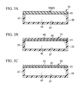
- Fig. 3A is a sectional view taken along line III-III in Fig. 1 showing that the housing is covered with the vibration member composed of a closed-cell porous material.
- Fig. 3B is a sectional view taken along line III-III in Fig. 1 showing that the housing is covered with the vibration member composed of a closed-cell porous material and an open-cell porous material.
- Fig. 3C is a sectional view taken along line III-III in Fig. 1 showing that the housing is covered with the vibration member composed of a closed-cell porous material and an air-permeable member.
- Fig. 4A is a sectional view diagrammatically showing the closed-cell porous material including a plurality of closed cells.
- Fig. 4B is a sectional view diagrammatically showing the open-cell porous material including a plurality of open cells.
- Fig. 5 is a graph showing open-cell and closed-cell characteristic curves based on experimental results with a 10-mm-thickness air cavity formed in the rear side of the vibration member in the sound absorbing structure.
- Fig. 6 is a graph showing open-cell and closed-cell characteristic curves based on experimental results with a 20-mm-thickness air cavity formed in the rear side of the vibration member in the sound absorbing structure.
- Fig. 7 is a graph showing open-cell and closed-cell characteristic curves based on experimental results with a 30-mm-thickness air cavity formed in the rear side of the vibration member in the sound absorbing structure.
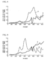
- Fig. 8 is a graph showing open-cell and closed-cell characteristic curves based on experimental results with a 10-mm-thickness air cavity formed in the rear side of the vibration member in the sound absorbing structure.
- Fig. 9 is a graph showing open-cell and closed-cell characteristic curves based on experimental results with a 20-mm-thickness air cavity formed in the rear side of the vibration member in the sound absorbing structure.
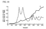
- Fig. 10 is a graph showing open-cell and closed-cell characteristic curves based on experimental results with a 30-mm-thickness air cavity formed in the rear side of the vibration member in the sound absorbing structure.
- Fig. 11 is a graph showing simulation results of normal incidence sound absorption coefficients on a sound absorbing structure according to a third variation of the present embodiment, wherein five characteristic curves are plotted with respect to various surface densities at the center of the vibration member.
- Fig. 1 is a perspective view showing the constitution of a sound absorbing structure 10 according to a preferred embodiment of the present invention.
- Fig. 2 is an exploded perspective view of the sound absorbing structure 10.
- Figs. 3A to 3C are sectional views taken along line III-III in Fig. 1 .
- Figs. 1 and 2 and Figs 3A to 3C are illustrated with prescribed dimensions, which do not precisely match the actual design dimensions, in order to distinctively show the constituent elements of the sound absorbing structure 10.
- the sound absorbing structure 10 is constituted of a housing 20 (serving as the base of the sound absorbing structure 10), a vibration member 30 for covering an opening 23 of the housing 20, and an air cavity 40 which is formed inside the housing 20 equipped with the vibration member 30.
- the housing 20 is formed in a closed-bottom rectangular prismatic shape composed of a synthetic resin (e.g. an ABS resin), which is constituted of a base 21 and a side wall 22 as well as the opening 23.
- the base 21 is disposed opposite to the opening 23, while the side wall 22 is disposed to encompass the opening 23.
- the vibration member 30 is a squared board composed of a high polymer compound (e.g. a silicon foam, a urethane foam, a polyethylene foam, an ethylene-propylene rubber foam, etc.).
- the periphery of the vibration member 30 is bonded to the edge of the opening 23. Since the vibration member 30 is fixed upon the opening 23 of the housing 20, a tightly-closed air cavity 40 is formed inside the sound absorbing structure 10 (or in the rear side of the vibration member 30).
- the vibration member 30 is not necessarily formed in a plate (or board) shape but is formed in a film (or membrane) shape. In short, the present embodiment requires that the vibration member 30 be formed of any type of material which is deformable upon receiving an external force and is restorable in shape due to elasticity.
- the plate shape is defined as a thin three-dimensional shape (or a rectangular parallelepiped shape) which is reduced in thickness and is enlarged in a two-dimensional area, while the film shape (or sheet shape) is further reduced in thickness compared to the plate shape and is restorable in shape due to tension.
- the vibration member 30 is formed in a prescribed shape and of a prescribed material which is reduced in terms of a rigidity (i.e. a Young's modulus, a thickness, and a geometrical moment of inertia) and/or a mechanical impedance, i.e. 8x ⁇ (bending rigidity)x(surface density) ⁇ 1/2 , in comparison with the housing 20. That is, the vibration member 30 possesses elastic-vibration ability relative to the housing 20, so that the sound absorbing structure 10 demonstrates the sound absorbing operation by means of the vibration member 30.
- a rigidity i.e. a Young's modulus, a thickness, and a geometrical moment of inertia
- a mechanical impedance i.e. 8x ⁇ (bending rigidity)x(surface density) ⁇ 1/2
- the sound absorbing structure 10 having the above basic constitution is characterized in that the vibration member 30 is formed using a closed-cell porous material 50 shown in Fig. 3A .
- the airflow rate of the closed-cell porous material 50 is less than 0.1 dm 3 /s, thus shutting off an airflow therethrough.
- the closed-cell porous material it is possible to use a silicon foam and an ethylene-propylene rubber foam (or EPDM, i.e. ethylene-propylene-diene-methylene rubber), for example.
- Figs. 4A and 4B illustrate the cross-sectional comparison between the closed-cell porous material 50 and an open-cell porous material 60.
- closed-cell porous material 50 shown in Fig. 4A a plurality of closed cells 51 do not communicate with each other and overlap with each other so that they are independent of each other.
- the closed-cell porous material 51 having elasticity serves as an integrally vibrating board, in other words, the closed-cell porous material 51 has elasticity but does not have air permeability.
- Fig. 4A diagrammatically shows that the closed cells 51 are regularly aligned, but they may be aligned in a random manner; that is, the closed-cell porous material 50 includes the closed cells 51, which do not overlap with each other, so as to prevent an airflow occurring between the surface and the backside thereof.
- a plurality of open cells 61 partially overlap with each other and communicate with each other; hence, the open-cell porous material 60 has a sponge-like texture dependent upon the material and the size of the cell 61.
- Fig. 4B diagrammatically shows that the open cells 61 are regularly aligned, but they may be aligned in a random manner; that is, the open-cell porous material 60 includes the open cells 61, which adjoin together to partially overlap with each other, so as to establish an air flow occurring between the surface and the backside thereof.
- the sound absorbing structure 10 serves as a spring-mass system composed of the mass of the vibration member 30 and the spring component of the air cavity 40.
- a resonance frequency f [Hz] of the spring-mass system is given by equation (1) using an air density ⁇ 0 [kg/m 3 ], the speed of sound c 0 [m/s], a density ⁇ [kg/m 3 ], a thickness t [m] of the vibration member 30, and a thickness L [m] of the air cavity 40.
- f 1 2 ⁇ ⁇ ⁇ ⁇ 0 ⁇ c 0 2 ⁇ tL 1 / 2
- the sound absorbing structure 10 includes the vibration member 30 having elasticity subjected to elastic vibration, a bending system (representing the elastic vibration) is applied to the spring-mass system.
- a resonance frequency f [Hz] of a plate/film-vibrating sound absorbing structure is given by equation (2) using a one-side length "a" [m] and another-side length "b” [m] of the rectangular shape of the vibration member 30, a Poisson ratio ⁇ [-] of the vibration member 30, and integral numbers p, q.
- the calculation result of the above resonance frequency f is used for architectural acoustic designs.
- the resonance frequency f represents the sum of the term of the spring-mass system " ⁇ 0 c 0 2 / ⁇ tL" and the term of the bending system (i.e. the term directly subsequent to the term of the spring-mass system).
- the spring-mass system of the vibration member 30 and the bending system representing the elastic vibration form important factors determining the sound absorbing condition for the sound absorbing structure 10.
- the vibration member 30 is subjected to elastic vibration dependent upon the difference between the external sound pressure applied to the exterior surface of the vibration member 30 and the internal sound pressure occurring inside the air cavity 40, in other words, the sound-pressure difference between the surface and the backside of the vibration member 30. Sound is absorbed in such a way that energy of sound waves reaching the sound absorbing structure 10 is consumed by way of the vibration of the vibration member 30.
- the vibration member 30 absorbs sound in a certain frequency range whose center frequency corresponds to the resonance frequency f according to equation (2).
- Figs. 5 to 7 are graphs of characteristic curves representing results of experiments in which sounds having various frequencies are applied to sound absorbing structures (i.e. experimental subjects) so as to measure normal incidence sound absorbing coefficients.
- Figs. 5 to 7 show experimental results with respect to two types of sound absorbing structures, one of which includes an open-cell type vibration member composed of a 10-mm-thickness open-cell urethane foam and the other of which includes a closed-cell type vibration member composed of a 10-mm-thickness closed-cell silicon foam. That is, an open-cell characteristic curve A represents the sound absorption characteristic regarding the open-cell type vibration member, while a closed-cell characteristic curve B represents the sound absorption characteristic regarding the closed-cell type vibration member.
- Figs. 5 to 7 differ from each other in terms of the thickness of an air cavity formed in the rear side of the vibration member; that is, Fig. 5 shows the experimental result with regard to a 10-mm-thickness air cavity; Fig. 6 shows the experimental result with regard to a 20-mm-thickness air cavity; and Fig. 7 shows the experimental result with regard to a 30-mm-thickness air cavity.
- the open-cell characteristic curves A of Figs. 5 to 7 show that sound absorption coefficients decrease in a low frequency range but increase in a high frequency range, while the closed-cell characteristic curves B show that sound absorption coefficients peak at maximum values in a further low frequency range.
- the sound absorbing structure 10 including the vibration member 30 composed of a closed-cell porous material demonstrates an adequate sound absorbing effect.
- the density of the closed-cell porous material is set to 250 kg/m 3
- the density of the open-cell porous material is set to 35 kg/m 3 .
- Figs. 8 to 10 show experimental results with respect to two types of sound absorbing structures, one of which includes an open-cell type vibration member composed of a 10-mm-thickness open-cell urethane foam and the other of which includes a closed-cell type vibration member composed of a 10-mm-thickness closed-cell EPDM, i.e. an ethylene-propylene-diene-methylene rubber.
- an open-cell characteristic curve A represents the sound absorption characteristic regarding the open-cell type vibration member
- a closed-cell characteristic curve B represents the sound absorption characteristic regarding the closed-cell type vibration member.
- Figs. 8 to 10 differ from each other in terms of the thickness of an air cavity formed in the rear side of the vibration member; that is, Fig. 8 shows the experimental result with regard to a 10-mm-thickness air cavity; Fig. 9 shows the experimental result with regard to a 20-mm-thickness air cavity; and Fig. 10 shows the experimental result with regard to a 30-mm-thickness air cavity.
- the sound absorbing structure 10 including the vibration member 30 composed of the closed-cell porous material 50 is capable of absorbing sound in a low frequency range regardless of the "slim" thickness of the vibration member 30 and the air cavity 40 in total which is 50 mm or less.
- the closed-cell porous material 50 shuts off an airflow therethrough, it is possible to prevent external air from entering into the air cavity 40 via the vibration member 30 even when the sound absorbing structure 10 is positioned in a dusty sound field or environment. That is, it is possible to prevent the air cavity 40 from being contaminated with dust or foreign matter.
- the closed-cell porous material 50 inherently blocks air or humidity entering therein, it is possible to enhance the durability of the vibration member 30 and to thereby improve the reliability of the sound absorbing structure 10.
- the closed-cell porous material 50 is lower in manufacturing cost than the open-cell porous material 60, it is possible to manufacture the sound absorbing structure 10 at a relatively low cost. Since it is easier to perform cutting on the closed-cell porous material 50 rather than the open-cell porous material 60, it is possible to improve the productivity. As described above, the present embodiment demonstrates various outstanding effects.
- the present embodiment exemplifies the sound absorbing structure 10 including the vibration member 30 composed of the closed-cell porous material 50, which can be modified in various ways.
- Fig. 3B is a sectional view of a vibration member 31 in which the open-cell porous material 60 is laminated on the surface (i.e. the sound-incidence side) of the closed-cell porous material 50.
- the vibration member 31 is fixed to the housing 20 in such a way that the air cavity 40 is formed in the rear side of the closed-cell porous material 50.
- Fig. 3C is a sectional view of a vibration member 32 in which an air-permeable member 70 composed of a fabric material such as a mesh, cloth, and flocked fabric is laminated on the surface (i.e. the sound-incidence side) of the closed-cell porous material 50.
- the vibration member 32 is fixed to the housing 20 in such a way that the air cavity 40 is formed in the rear side of the closed-cell porous material 50.
- the vibration member 31 it is possible to further modify the vibration member 31 such that three or more layers of the open-cell porous material 60 are laminated on the closed-cell porous material 50.
- the first variation requires that the vibration member be formed using the closed-cell porous material 50 so as to reliably shut off the airflow occurring between the air cavity 40 and the external air.
- the present inventor performed various detailed experiments so as to determine inequality (3) regarding the relationship between a fundamental frequency fa of the bending system and a resonance frequency fb of the spring-mass system.
- inequality (3) the present inventor actually verified an improvement of the sound absorption, since the fundamental vibration of the bending system cooperates with the spring component of the rear air cavity so that a relatively high amplitude of vibration occurs in a frequency band between the resonance frequency of the spring-mass system and the fundamental frequency of the bending system, i.e. (resonance frequency fa of bending system) ⁇ (peak sound-absorption frequency f) ⁇ (fundamental frequency fb of spring-mass system).
- the sound absorbing structure including parameters according to inequality (4) is suitable for absorbing sound in a low frequency range which is 300 Hz or less, since the fundamental frequency of the bending system is sufficiently lowered due to a low-degree elastic vibration mode.
- the present embodiment exemplifies the sound absorbing structure 10 which is constituted of the rectangular housing 20, the vibration member 30 for closing the opening 23 of the housing 20, and the air cavity 40 formed inside the housing 20.
- the housing 20 is not necessarily formed in a rectangular shape, which can be changed to other shapes such as a circular shape and a polygonal shape.
- the sound absorbing structure 10 possesses a sound absorption mechanism composed of the spring-mass system and the bending system.
- the present inventor performed experiments on sound absorption coefficients at resonance frequencies with various surface densities applied to the vibration member 30.
- Fig. 11 show simulation results on normal incidence sound absorption coefficients with respect to the sound absorbing structure 10, in which the vibration member 30 having the length and breadth of 100 mm ⁇ 100 mm and the thickness of 0.85 mm is fixed to the housing 20 containing the air cavity 40 having the length and breadth of 100 mm ⁇ 100 mm and the thickness of 10 mm and in which the surface density is changed with respect to the center portion having the length and breadth of 20 mm ⁇ 20 mm and the thickness of 0.85 mm.
- the simulation is performed based on JIS A 1405-2 (titled “Acoustics - Determination of sound absorption coefficient and impedance in impedance tubes - Part 2: Transfer-function method") so as to determine a sound field of a sound chamber for arranging the sound absorbing structure 10 in accordance with the finite element method, thus calculating sound absorption characteristics by way of transfer functions.
- Fig. 11 shows five characteristic curves D1 to D5 which are plotted using the same surface density of the periphery of the vibration member 30 of 799 g/m 2 while changing the surface density of the center portion of the vibration member 30 as 399.5 g/m 2 799 g/m 2 , 1199 g/m 2 , 1598 g/m 2 , and 2297 g/m 2 in D1, D2, D3, D4, and D5 respectively.
- the average density of the vibration member 30 is set to 783 g/m 2 , 799 g/m 2 , 815 g/m 2 831 g/m 2 , and 863- g/m 2 in D1, D2, D3, D4, and D5 respectively.
- the simulation results of Fig. 11 clarify that sound absorption coefficients peak in a frequency range between 300 Hz and 500 Hz and at a frequency around 700 Hz.
- Sound absorption coefficients peak around 700 Hz due to the resonance of the spring-mass system composed of the mass of the vibration member 30 and the spring component of the air cavity 40.
- the sound absorbing structure 10 absorbs sound in such a way that the sound absorption coefficient peaks at the resonance frequency of the bending system in a low frequency range, wherein the resonance frequency of the bending system gradually decreases as the surface density of the center portion of the vibration member 30 increases.
- the resonance frequency of the bending system is determined by the equation of motion directing the elastic vibration of the vibration member 30 and varies in inverse proportion to the surface density of the vibration member 30.
- the resonance frequency is greatly affected by the density of the antinode of the characteristic vibration (at which the amplitude becomes maximum).
- the simulation is performed by changing the surface density of the center portion with respect to the antinode region of 1 ⁇ 1 characteristic mode, thus causing variations of the resonance frequency of the bending system.
- the simulation result clarifies that, by increasing the surface density of the center portion to be higher than the surface density of the periphery, the prescribed frequencies causing peak sound absorption coefficients are further lowered in a low frequency range.
- the prescribed frequencies causing peak sound absorption coefficients are further lowered in a low frequency range.
- the sound absorbing structure 10 is capable of shifting the prescribed frequency causing a peak sound absorption coefficient by simply changing the surface density of the center portion of the vibration member 30, it is possible to lower the sound absorption frequency without greatly changing the overall weight of the sound absorbing structure 10 in contrast to a typical example of the sound absorbing structure whose sound absorption frequency is changed by increasing the overall weight.
- a sound absorbent group including a plurality of sound absorbing structures it is possible to form a sound absorbent group including a plurality of sound absorbing structures according to one of the present embodiment and variations. Alternatively, it is possible to form a sound absorbent group including a plurality of sound absorbing structures having different sound absorption characteristics or a plurality of sound absorbing structures having three or more different sound absorption characteristics.
- the sound absorbing structure and the sound absorbent group are applicable to various types of sound chambers having controlled acoustic characteristics such as soundproof chambers, halls, theaters, listening rooms of audio devices, conference rooms, compartment spaces of transportation such as vehicles, and housings of speakers and musical instruments.
Landscapes
- Physics & Mathematics (AREA)
- Engineering & Computer Science (AREA)
- Acoustics & Sound (AREA)
- Multimedia (AREA)
- Soundproofing, Sound Blocking, And Sound Damping (AREA)
- Building Environments (AREA)
Abstract
A sound absorbing structure (10) is constituted of a housing (20), a vibration member (30) composed of a closed-cell porous material whose airflow rate is less than 0.1 dm3/s, and an air cavity (40) formed inside the housing in the rear side of the vibration member. Alternatively, the vibration member is formed by laminating an open-cell porous material or an air-permeable member with the closed-cell porous material. The sound absorbing structure demonstrates a high sound absorption in a low frequency range due to the closed-cell porous material.
Description
- The present invention relates to sound absorbing structures using closed-cell porous media. The present invention also relates to sound chambers using sound absorbing structures.
- The present application claims priority on Japanese Patent Application No.
2008-211972 - In generally-known sound absorbing structures using open-cell porous media (e.g. glass wools), the sound absorption increases proportionally to the particle velocity of sound waves so that it becomes high in a high frequency range but it becomes low in a low frequency range. Generating high sound absorption in a low frequency range requires sound absorbing structures having a thickness of about λ/4 (e.g. 34 cm for 250 Hz), which are difficult to be installed in a small space.
- It is possible to generate a high sound absorption in a low frequency range by use of a sound absorbing structure which absorbs sound by way of a plate or membrane vibration member and its rear air cavity, wherein a laminated board having a thickness of 4 mm is equipped with a rear air cavity having a thickness of 45 mm which is filled with glass wools therein, so that the sound absorption coefficient thereof peaks at 0.6 in a low frequency of 250 Hz, for example.
Patent Document 1: Japanese Unexamined Patent Application Publication No.2003-316364
Patent Document 2: Japanese Unexamined Patent Application Publication No. - Patent Document 1 discloses sound absorbing media using open-cell porous materials (or cellular porous materials), which are well known in the fields of sound absorbing technology.
- Patent Document 2 discloses sound absorbing media using open-cell porous materials and closed-cell porous materials with an airflow rate of 0.1 dm3/s or more. A high airflow rate does not cause a sound pressure difference between the surface and the backside of the porous material, which in turn makes it difficult for a plate vibration member to vibrate, thus degrading a sound absorbing effect of a plate-vibration sound absorbing structure.
- It is an object of the present invention to provide a sound absorbing structure using a closed-cell porous material having elasticity but not having air permeability. Specifically, the present invention aims at demonstrating a high sound absorbing effect in a low frequency range with a thin sound absorbing structure whose total thickness (i.e. the sum of the thickness of a porous material and the thickness of a rear air cavity) is about 50 mm.
- A sound absorbing structure of the present invention is constituted of a vibration member composed of a closed-cell porous material, and an air cavity formed in the rear side of the vibration member.
- Alternatively, the vibration member is formed by laminating an open-cell porous material with the closed-cell porous material or by laminating an air-permeable member with the closed-cell porous material.
- In the above, it is preferable that an airflow rate of the closed-cell porous material be less than 0.1 dm3/s.
- A sound absorbent group is formed using a plurality of sound absorbing structures, each of which is constituted of the vibration member and the air cavity.
- A sound chamber is formed using at least one sound absorbing structure including the vibration member and the air cavity.
- As described above, the sound absorbing structure of the present invention is a plate/film-vibration sound absorbing structure in which the air cavity formed inside the housing is closed with the vibration member composed of the closed-cell porous material, wherein it is possible to prevent the degradation of the vibration member while securing high sound absorption characteristics, thus improving the reliability in sound absorption.
- These and other objects, aspects, and embodiments of the present invention will be described in more detail with reference to the following drawings.
-
Fig. 1 is a perspective view showing the constitution of a sound absorbing structure according to a preferred embodiment of the present invention. -
Fig. 2 is an exploded perspective view of the sound absorbing structure which is constituted of a housing, a vibration member, and an air cavity. -
Fig. 3A is a sectional view taken along line III-III inFig. 1 showing that the housing is covered with the vibration member composed of a closed-cell porous material. -
Fig. 3B is a sectional view taken along line III-III inFig. 1 showing that the housing is covered with the vibration member composed of a closed-cell porous material and an open-cell porous material. -
Fig. 3C is a sectional view taken along line III-III inFig. 1 showing that the housing is covered with the vibration member composed of a closed-cell porous material and an air-permeable member. -
Fig. 4A is a sectional view diagrammatically showing the closed-cell porous material including a plurality of closed cells. -
Fig. 4B is a sectional view diagrammatically showing the open-cell porous material including a plurality of open cells. -
Fig. 5 is a graph showing open-cell and closed-cell characteristic curves based on experimental results with a 10-mm-thickness air cavity formed in the rear side of the vibration member in the sound absorbing structure. -
Fig. 6 is a graph showing open-cell and closed-cell characteristic curves based on experimental results with a 20-mm-thickness air cavity formed in the rear side of the vibration member in the sound absorbing structure. -
Fig. 7 is a graph showing open-cell and closed-cell characteristic curves based on experimental results with a 30-mm-thickness air cavity formed in the rear side of the vibration member in the sound absorbing structure. -
Fig. 8 is a graph showing open-cell and closed-cell characteristic curves based on experimental results with a 10-mm-thickness air cavity formed in the rear side of the vibration member in the sound absorbing structure. -
Fig. 9 is a graph showing open-cell and closed-cell characteristic curves based on experimental results with a 20-mm-thickness air cavity formed in the rear side of the vibration member in the sound absorbing structure. -
Fig. 10 is a graph showing open-cell and closed-cell characteristic curves based on experimental results with a 30-mm-thickness air cavity formed in the rear side of the vibration member in the sound absorbing structure. -
Fig. 11 is a graph showing simulation results of normal incidence sound absorption coefficients on a sound absorbing structure according to a third variation of the present embodiment, wherein five characteristic curves are plotted with respect to various surface densities at the center of the vibration member. - The present invention will be described in further detail by way of examples with reference to the accompanying drawings.
-
Fig. 1 is a perspective view showing the constitution of asound absorbing structure 10 according to a preferred embodiment of the present invention.Fig. 2 is an exploded perspective view of thesound absorbing structure 10.Figs. 3A to 3C are sectional views taken along line III-III inFig. 1 . For the sake of convenience,Figs. 1 and 2 andFigs 3A to 3C are illustrated with prescribed dimensions, which do not precisely match the actual design dimensions, in order to distinctively show the constituent elements of thesound absorbing structure 10. - The
sound absorbing structure 10 is constituted of a housing 20 (serving as the base of the sound absorbing structure 10), avibration member 30 for covering an opening 23 of thehousing 20, and anair cavity 40 which is formed inside thehousing 20 equipped with thevibration member 30. - The
housing 20 is formed in a closed-bottom rectangular prismatic shape composed of a synthetic resin (e.g. an ABS resin), which is constituted of abase 21 and aside wall 22 as well as the opening 23. Thebase 21 is disposed opposite to the opening 23, while theside wall 22 is disposed to encompass the opening 23. Thevibration member 30 is a squared board composed of a high polymer compound (e.g. a silicon foam, a urethane foam, a polyethylene foam, an ethylene-propylene rubber foam, etc.). The periphery of thevibration member 30 is bonded to the edge of the opening 23. Since thevibration member 30 is fixed upon the opening 23 of thehousing 20, a tightly-closedair cavity 40 is formed inside the sound absorbing structure 10 (or in the rear side of the vibration member 30). - The
vibration member 30 is not necessarily formed in a plate (or board) shape but is formed in a film (or membrane) shape. In short, the present embodiment requires that thevibration member 30 be formed of any type of material which is deformable upon receiving an external force and is restorable in shape due to elasticity. - In this connection, the plate shape is defined as a thin three-dimensional shape (or a rectangular parallelepiped shape) which is reduced in thickness and is enlarged in a two-dimensional area, while the film shape (or sheet shape) is further reduced in thickness compared to the plate shape and is restorable in shape due to tension.
- The
vibration member 30 is formed in a prescribed shape and of a prescribed material which is reduced in terms of a rigidity (i.e. a Young's modulus, a thickness, and a geometrical moment of inertia) and/or a mechanical impedance, i.e. 8x{(bending rigidity)x(surface density)}1/2, in comparison with thehousing 20. That is, thevibration member 30 possesses elastic-vibration ability relative to thehousing 20, so that thesound absorbing structure 10 demonstrates the sound absorbing operation by means of thevibration member 30. - The
sound absorbing structure 10 having the above basic constitution is characterized in that thevibration member 30 is formed using a closed-cellporous material 50 shown inFig. 3A . The airflow rate of the closed-cellporous material 50 is less than 0.1 dm3/s, thus shutting off an airflow therethrough. As the closed-cell porous material, it is possible to use a silicon foam and an ethylene-propylene rubber foam (or EPDM, i.e. ethylene-propylene-diene-methylene rubber), for example. -
Figs. 4A and 4B illustrate the cross-sectional comparison between the closed-cellporous material 50 and an open-cellporous material 60. - In the closed-cell
porous material 50 shown inFig. 4A , a plurality ofclosed cells 51 do not communicate with each other and overlap with each other so that they are independent of each other. The closed-cellporous material 51 having elasticity serves as an integrally vibrating board, in other words, the closed-cellporous material 51 has elasticity but does not have air permeability. -
Fig. 4A diagrammatically shows that theclosed cells 51 are regularly aligned, but they may be aligned in a random manner; that is, the closed-cellporous material 50 includes theclosed cells 51, which do not overlap with each other, so as to prevent an airflow occurring between the surface and the backside thereof. - In the open-cell
porous material 60 shown inFig. 4B , a plurality ofopen cells 61 partially overlap with each other and communicate with each other; hence, the open-cellporous material 60 has a sponge-like texture dependent upon the material and the size of thecell 61.Fig. 4B diagrammatically shows that theopen cells 61 are regularly aligned, but they may be aligned in a random manner; that is, the open-cellporous material 60 includes theopen cells 61, which adjoin together to partially overlap with each other, so as to establish an air flow occurring between the surface and the backside thereof. - Generally speaking, the
sound absorbing structure 10 serves as a spring-mass system composed of the mass of thevibration member 30 and the spring component of theair cavity 40. - A resonance frequency f [Hz] of the spring-mass system is given by equation (1) using an air density ρ0 [kg/m3], the speed of sound c0 [m/s], a density ρ [kg/m3], a thickness t [m] of the
vibration member 30, and a thickness L [m] of theair cavity 40.
- When the
sound absorbing structure 10 includes thevibration member 30 having elasticity subjected to elastic vibration, a bending system (representing the elastic vibration) is applied to the spring-mass system. - A resonance frequency f [Hz] of a plate/film-vibrating sound absorbing structure is given by equation (2) using a one-side length "a" [m] and another-side length "b" [m] of the rectangular shape of the
vibration member 30, a Poisson ratio σ [-] of thevibration member 30, and integral numbers p, q. In the field of architectural acoustics, the calculation result of the above resonance frequency f is used for architectural acoustic designs.
- According to equation (2), the resonance frequency f represents the sum of the term of the spring-mass system "ρ0c0 2/ρtL" and the term of the bending system (i.e. the term directly subsequent to the term of the spring-mass system). According to equation (2), the spring-mass system of the
vibration member 30 and the bending system representing the elastic vibration form important factors determining the sound absorbing condition for thesound absorbing structure 10. - In the
sound absorbing structure 10 of the present embodiment, thevibration member 30 is subjected to elastic vibration dependent upon the difference between the external sound pressure applied to the exterior surface of thevibration member 30 and the internal sound pressure occurring inside theair cavity 40, in other words, the sound-pressure difference between the surface and the backside of thevibration member 30. Sound is absorbed in such a way that energy of sound waves reaching thesound absorbing structure 10 is consumed by way of the vibration of thevibration member 30. Thevibration member 30 absorbs sound in a certain frequency range whose center frequency corresponds to the resonance frequency f according to equation (2). - The sound absorbing effect of the
sound absorbing structure 10 will be described with reference toFigs. 5 to 7. Figs. 5 to 7 are graphs of characteristic curves representing results of experiments in which sounds having various frequencies are applied to sound absorbing structures (i.e. experimental subjects) so as to measure normal incidence sound absorbing coefficients. - Specifically,
Figs. 5 to 7 show experimental results with respect to two types of sound absorbing structures, one of which includes an open-cell type vibration member composed of a 10-mm-thickness open-cell urethane foam and the other of which includes a closed-cell type vibration member composed of a 10-mm-thickness closed-cell silicon foam. That is, an open-cell characteristic curve A represents the sound absorption characteristic regarding the open-cell type vibration member, while a closed-cell characteristic curve B represents the sound absorption characteristic regarding the closed-cell type vibration member. - In addition,
Figs. 5 to 7 differ from each other in terms of the thickness of an air cavity formed in the rear side of the vibration member; that is,Fig. 5 shows the experimental result with regard to a 10-mm-thickness air cavity;Fig. 6 shows the experimental result with regard to a 20-mm-thickness air cavity; andFig. 7 shows the experimental result with regard to a 30-mm-thickness air cavity. - The open-cell characteristic curves A of
Figs. 5 to 7 show that sound absorption coefficients decrease in a low frequency range but increase in a high frequency range, while the closed-cell characteristic curves B show that sound absorption coefficients peak at maximum values in a further low frequency range. This proves that thesound absorbing structure 10 including thevibration member 30 composed of a closed-cell porous material demonstrates an adequate sound absorbing effect. In the above, the density of the closed-cell porous material is set to 250 kg/m3, while the density of the open-cell porous material is set to 35 kg/m3. -
Figs. 8 to 10 show experimental results with respect to two types of sound absorbing structures, one of which includes an open-cell type vibration member composed of a 10-mm-thickness open-cell urethane foam and the other of which includes a closed-cell type vibration member composed of a 10-mm-thickness closed-cell EPDM, i.e. an ethylene-propylene-diene-methylene rubber. Herein, an open-cell characteristic curve A represents the sound absorption characteristic regarding the open-cell type vibration member, while a closed-cell characteristic curve B represents the sound absorption characteristic regarding the closed-cell type vibration member. - In addition,
Figs. 8 to 10 differ from each other in terms of the thickness of an air cavity formed in the rear side of the vibration member; that is,Fig. 8 shows the experimental result with regard to a 10-mm-thickness air cavity;Fig. 9 shows the experimental result with regard to a 20-mm-thickness air cavity; andFig. 10 shows the experimental result with regard to a 30-mm-thickness air cavity. - Similar to the experimental results of
Figs. 5 to 7 , the experimental results ofFigs. 8 to 10 , which are measured using the closed-cell vibration member composed of EPDM, sound absorption coefficients peak at maximum values in a low frequency range. - According to the above experimental results, the
sound absorbing structure 10 including thevibration member 30 composed of the closed-cellporous material 50 is capable of absorbing sound in a low frequency range regardless of the "slim" thickness of thevibration member 30 and theair cavity 40 in total which is 50 mm or less. - Since the closed-cell
porous material 50 shuts off an airflow therethrough, it is possible to prevent external air from entering into theair cavity 40 via thevibration member 30 even when thesound absorbing structure 10 is positioned in a dusty sound field or environment. That is, it is possible to prevent theair cavity 40 from being contaminated with dust or foreign matter. - Since the closed-cell
porous material 50 inherently blocks air or humidity entering therein, it is possible to enhance the durability of thevibration member 30 and to thereby improve the reliability of thesound absorbing structure 10. - Since the closed-cell
porous material 50 is lower in manufacturing cost than the open-cellporous material 60, it is possible to manufacture thesound absorbing structure 10 at a relatively low cost. Since it is easier to perform cutting on the closed-cellporous material 50 rather than the open-cellporous material 60, it is possible to improve the productivity. As described above, the present embodiment demonstrates various outstanding effects. - The present invention is not necessarily limited to the present embodiment, which can be modified in various ways.
- The present embodiment exemplifies the
sound absorbing structure 10 including thevibration member 30 composed of the closed-cellporous material 50, which can be modified in various ways. -
Fig. 3B is a sectional view of avibration member 31 in which the open-cellporous material 60 is laminated on the surface (i.e. the sound-incidence side) of the closed-cellporous material 50. Thevibration member 31 is fixed to thehousing 20 in such a way that theair cavity 40 is formed in the rear side of the closed-cellporous material 50. -
Fig. 3C is a sectional view of avibration member 32 in which an air-permeable member 70 composed of a fabric material such as a mesh, cloth, and flocked fabric is laminated on the surface (i.e. the sound-incidence side) of the closed-cellporous material 50. Thevibration member 32 is fixed to thehousing 20 in such a way that theair cavity 40 is formed in the rear side of the closed-cellporous material 50. - It is possible to demonstrate the foregoing effect of the present embodiment by use of the
vibration members porous material 60 or the air-permeability member 70 on the surface of the closed-cellporous material 50, it is possible to demonstrate an additional effect that sound is easily absorbed by thematerial - It is possible to further modify the
vibration member 31 such that three or more layers of the open-cellporous material 60 are laminated on the closed-cellporous material 50. Alternatively, it is possible to further laminate the air-permeability member 70 on the open-cellporous material 60 above the closed-cellporous material 50. In short, the first variation requires that the vibration member be formed using the closed-cellporous material 50 so as to reliably shut off the airflow occurring between theair cavity 40 and the external air. - Although the relevancy between the resonance frequency of the spring-mass system and the resonance frequency of the bending system based on the elastic vibration of the plate is univocally defined by equation (2), the actual behavior of the sound absorbing structure has not been fully clarified, hence, the actual working model of the sound absorbing structure demonstrating a high sound absorption in a low frequency range has not been established.
- For this reason, the present inventor performed various detailed experiments so as to determine inequality (3) regarding the relationship between a fundamental frequency fa of the bending system and a resonance frequency fb of the spring-mass system. By setting parameters to suit inequality (3), the present inventor actually verified an improvement of the sound absorption, since the fundamental vibration of the bending system cooperates with the spring component of the rear air cavity so that a relatively high amplitude of vibration occurs in a frequency band between the resonance frequency of the spring-mass system and the fundamental frequency of the bending system, i.e. (resonance frequency fa of bending system) < (peak sound-absorption frequency f) < (fundamental frequency fb of spring-mass system).

- By setting parameters to suit inequality (4), it is possible to substantially make the peak sound-absorption frequency lower than the resonance frequency of the spring-mass system. Herein, the present inventor verified that the sound absorbing structure including parameters according to inequality (4) is suitable for absorbing sound in a low frequency range which is 300 Hz or less, since the fundamental frequency of the bending system is sufficiently lowered due to a low-degree elastic vibration mode.

- By setting parameters to suit inequalities (3) and (4), it is possible to design the sound absorbing structure whose peak sound-absorption frequency is lowered in a low frequency range.
- The present embodiment exemplifies the
sound absorbing structure 10 which is constituted of therectangular housing 20, thevibration member 30 for closing theopening 23 of thehousing 20, and theair cavity 40 formed inside thehousing 20. Thehousing 20 is not necessarily formed in a rectangular shape, which can be changed to other shapes such as a circular shape and a polygonal shape. In addition, it is possible to dispose the concentrated mass, which is an important factor for changing the vibration condition with respect to thevibration member 30, at the center of thevibration member 30. - As described above, the
sound absorbing structure 10 possesses a sound absorption mechanism composed of the spring-mass system and the bending system. The present inventor performed experiments on sound absorption coefficients at resonance frequencies with various surface densities applied to thevibration member 30. -
Fig. 11 show simulation results on normal incidence sound absorption coefficients with respect to thesound absorbing structure 10, in which thevibration member 30 having the length and breadth of 100 mm × 100 mm and the thickness of 0.85 mm is fixed to thehousing 20 containing theair cavity 40 having the length and breadth of 100 mm × 100 mm and the thickness of 10 mm and in which the surface density is changed with respect to the center portion having the length and breadth of 20 mm × 20 mm and the thickness of 0.85 mm. The simulation is performed based on JIS A 1405-2 (titled "Acoustics - Determination of sound absorption coefficient and impedance in impedance tubes - Part 2: Transfer-function method") so as to determine a sound field of a sound chamber for arranging thesound absorbing structure 10 in accordance with the finite element method, thus calculating sound absorption characteristics by way of transfer functions. - Specifically,
Fig. 11 shows five characteristic curves D1 to D5 which are plotted using the same surface density of the periphery of thevibration member 30 of 799 g/m2 while changing the surface density of the center portion of thevibration member 30 as 399.5 g/m2 799 g/m2, 1199 g/m2, 1598 g/m2, and 2297 g/m2 in D1, D2, D3, D4, and D5 respectively. Thus, the average density of thevibration member 30 is set to 783 g/m2, 799 g/m2, 815 g/m2 831 g/m2, and 863- g/m2 in D1, D2, D3, D4, and D5 respectively. - The simulation results of
Fig. 11 clarify that sound absorption coefficients peak in a frequency range between 300 Hz and 500 Hz and at a frequency around 700 Hz. - Sound absorption coefficients peak around 700 Hz due to the resonance of the spring-mass system composed of the mass of the
vibration member 30 and the spring component of theair cavity 40. Thesound absorbing structure 10 absorbs sound in such a way that the sound absorption coefficient peaks at the resonance frequency of the bending system in a low frequency range, wherein the resonance frequency of the bending system gradually decreases as the surface density of the center portion of thevibration member 30 increases. - Generally speaking, the resonance frequency of the bending system is determined by the equation of motion directing the elastic vibration of the
vibration member 30 and varies in inverse proportion to the surface density of thevibration member 30. The resonance frequency is greatly affected by the density of the antinode of the characteristic vibration (at which the amplitude becomes maximum). The simulation is performed by changing the surface density of the center portion with respect to the antinode region of 1×1 characteristic mode, thus causing variations of the resonance frequency of the bending system. - The simulation result clarifies that, by increasing the surface density of the center portion to be higher than the surface density of the periphery, the prescribed frequencies causing peak sound absorption coefficients are further lowered in a low frequency range. In other words, by changing the surface density of the center portion, it is possible to partially shift prescribed frequencies causing peak sound absorption coefficients to a further low frequency range or a further high frequency range.
- Since the
sound absorbing structure 10 is capable of shifting the prescribed frequency causing a peak sound absorption coefficient by simply changing the surface density of the center portion of thevibration member 30, it is possible to lower the sound absorption frequency without greatly changing the overall weight of thesound absorbing structure 10 in contrast to a typical example of the sound absorbing structure whose sound absorption frequency is changed by increasing the overall weight. - In this connection, it is possible to further increase the peak sound absorption coefficient by filling other porous sound-absorbent materials (e.g. resin foams, felts, cottony fibers such as polyester wools) inside the
air cavity 40 of thesound absorbing structure 10. - It is possible to form a sound absorbent group including a plurality of sound absorbing structures according to one of the present embodiment and variations. Alternatively, it is possible to form a sound absorbent group including a plurality of sound absorbing structures having different sound absorption characteristics or a plurality of sound absorbing structures having three or more different sound absorption characteristics.
- The sound absorbing structure and the sound absorbent group are applicable to various types of sound chambers having controlled acoustic characteristics such as soundproof chambers, halls, theaters, listening rooms of audio devices, conference rooms, compartment spaces of transportation such as vehicles, and housings of speakers and musical instruments.
- Lastly, the present invention is not necessarily limited to the present invention and variations, which can be further modified in a variety of ways within the scope of the invention defined by the appended claims.
Claims (12)
- A sound absorbing structure comprising:a vibration member composed of a closed-cell porous material; andan air cavity formed in a rear side of the vibration member.
- A sound absorbing structure comprising:a vibration member composed of a closed-cell porous material and an open-cell porous material which are laminated together; andan air cavity formed in a rear side of the closed-cell porous material.
- A sound absorbing structure comprising:a vibration member composed of a closed-cell porous material and an air-permeable member which are laminated together; andan air cavity formed in a rear side of the closed-cell porous material.
- The sound absorbing structure according to claim 1, wherein an airflow rate of the closed-cell porous material is less than 0.1 dm3/s.
- The sound absorbing structure according to claim 2, wherein an airflow rate of the closed-cell porous material is less than 0.1 dm3/s.
- The sound absorbing structure according to claim 3, wherein an airflow rate of the closed-cell porous material is less than 0.1 dm3/s.
- A sound absorbent group including a plurality of sound absorbing structures, each of which is constituted of a vibration member composed of a closed-cell porous material, and an air cavity formed in a rear side of the vibration member.
- A sound absorbent group including a plurality of sound absorbing structures, each of which is constituted of a vibration member composed of a closed-cell porous material and an open-cell porous material which are laminated together, and an air cavity formed in a rear side of the closed-cell porous material.
- A sound absorbent group including a plurality of sound absorbing structures, each of which is constituted of a vibration member composed of a closed-cell porous material and an air-permeable member which are laminated together, and an air cavity formed in a rear side of the closed-cell porous material.
- A sound chamber including at least one sound absorbing structure, which is constituted of a vibration member composed of a closed-cell porous material, and an air cavity formed in a rear side of the vibration member.
- A sound chamber including at least one sound absorbing structure, which is constituted of a vibration member composed of a closed-cell porous material and an open-cell porous material which are laminated together, and an air cavity formed in a rear side of the closed-cell porous material.
- A sound chamber including at least one sound absorbing structure, which is constituted of a vibration member composed of a closed-cell porous material and an air-permeable member which are laminated together, and an air cavity formed in a rear side of the closed-cell porous material.
Applications Claiming Priority (1)
| Application Number | Priority Date | Filing Date | Title |
|---|---|---|---|
| JP2008211972A JP5245641B2 (en) | 2008-08-20 | 2008-08-20 | Sound absorbing structure |
Publications (1)
| Publication Number | Publication Date |
|---|---|
| EP2157567A2 true EP2157567A2 (en) | 2010-02-24 |
Family
ID=41395109
Family Applications (1)
| Application Number | Title | Priority Date | Filing Date |
|---|---|---|---|
| EP09010237A Withdrawn EP2157567A2 (en) | 2008-08-20 | 2009-08-07 | Sound absorbing structure using closed-cell porous medium |
Country Status (3)
| Country | Link |
|---|---|
| US (1) | US20100044148A1 (en) |
| EP (1) | EP2157567A2 (en) |
| JP (1) | JP5245641B2 (en) |
Cited By (1)
| Publication number | Priority date | Publication date | Assignee | Title |
|---|---|---|---|---|
| CN103072588A (en) * | 2011-12-13 | 2013-05-01 | 杨弘 | Micro-perforated transparent plate sound absorption device for glazed partition and door at joint of carriages of high-speed train |
Families Citing this family (15)
| Publication number | Priority date | Publication date | Assignee | Title |
|---|---|---|---|---|
| JP5326472B2 (en) * | 2007-10-11 | 2013-10-30 | ヤマハ株式会社 | Sound absorption structure |
| EP2085962A2 (en) * | 2008-02-01 | 2009-08-05 | Yamaha Corporation | Sound absorbing structure and vehicle component having sound absorbing properties |
| US20090223738A1 (en) * | 2008-02-22 | 2009-09-10 | Yamaha Corporation | Sound absorbing structure and vehicle component having sound absorption property |
| DE102009007891A1 (en) * | 2009-02-07 | 2010-08-12 | Willsingh Wilson | Resonance sound absorber in multilayer design |
| JP5847715B2 (en) * | 2010-07-15 | 2016-01-27 | 日本音響エンジニアリング株式会社 | Open air layer vibration reduction structure |
| JP5816007B2 (en) * | 2011-07-08 | 2015-11-17 | 大成建設株式会社 | Sound absorbing material |
| CN104464709B (en) * | 2014-11-03 | 2017-11-17 | 江苏大学 | A kind of adaptive damping mechanical impedance compound sound-absorption structural |
| CN104751836A (en) * | 2015-03-03 | 2015-07-01 | 北京市劳动保护科学研究所 | Magnetic negative-stiffness sound absorption device and method |
| US9390700B1 (en) | 2015-03-10 | 2016-07-12 | Awi Licensing Llc | Laminate acoustic panel |
| US9615165B2 (en) * | 2015-08-07 | 2017-04-04 | Sound Solutions International Co., Ltd. | Loudspeaker device having foam insert to improve gas distribution in sound adsorber material |
| US9630575B2 (en) * | 2015-09-30 | 2017-04-25 | GM Global Technology Operations LLC | Panel assembly with noise attenuation system |
| JP2017197914A (en) * | 2016-04-25 | 2017-11-02 | 清水建設株式会社 | Sound absorbing structure |
| CN110249382B (en) * | 2017-02-16 | 2020-07-31 | 富士胶片株式会社 | Sound insulation structure |
| CN108915301A (en) * | 2018-07-03 | 2018-11-30 | 章娱信息科技(上海)有限公司 | Playroom |
| CN109388886B (en) * | 2018-10-09 | 2022-10-28 | 山东理工大学 | A Calculation Method of Sound Absorption Coefficient of Porous Materials |
Citations (3)
| Publication number | Priority date | Publication date | Assignee | Title |
|---|---|---|---|---|
| JP2003316364A (en) | 2002-02-20 | 2003-11-07 | Showa Electric Wire & Cable Co Ltd | Foam and acoustic material using the same, and method for manufacturing the same |
| JP2006011412A (en) | 2004-05-28 | 2006-01-12 | Showa Electric Wire & Cable Co Ltd | Film-like sound absorbing material and film-like sound absorbing structure using the same |
| JP2008211972A (en) | 2007-02-28 | 2008-09-18 | Iseki & Co Ltd | Operation device for seedling transplanter |
Family Cites Families (23)
| Publication number | Priority date | Publication date | Assignee | Title |
|---|---|---|---|---|
| US4214411A (en) * | 1978-01-16 | 1980-07-29 | The Fanwall Corporation | Panel and joint system and transparent acoustic barriers employing same |
| DE3220023C2 (en) * | 1982-05-27 | 1993-05-27 | Cellofoam Deutschland Gmbh, 7950 Biberach | Sound-absorbing flow channel and method for its manufacture |
| JPS59180593A (en) * | 1983-03-31 | 1984-10-13 | 三菱製鋼株式会社 | Low frequency sound absorbor |
| JPH089852B2 (en) * | 1990-04-11 | 1996-01-31 | 神鋼鋼線工業株式会社 | Sound absorption and sound insulation panel |
| CH686667A5 (en) * | 1992-09-23 | 1996-05-31 | Rieter Automotive Int Ag | Vibrationsdaempfende headliner construction. |
| US5369701A (en) * | 1992-10-28 | 1994-11-29 | At&T Corp. | Compact loudspeaker assembly |
| US5368500A (en) * | 1993-01-04 | 1994-11-29 | Dedering; Charles E. | Closure for electric plug |
| DE4414566C2 (en) * | 1994-04-27 | 1997-11-20 | Freudenberg Carl Fa | Air silencer |
| US6789645B1 (en) * | 1999-06-09 | 2004-09-14 | The Dow Chemical Company | Sound-insulating sandwich element |
| JP2002082671A (en) * | 2000-09-06 | 2002-03-22 | Nichias Corp | Sound absorbing structure |
| JP2002180845A (en) * | 2000-12-12 | 2002-06-26 | Nichias Corp | Soundproof cover for automobile engine |
| WO2002059870A1 (en) * | 2001-01-23 | 2002-08-01 | Kasai Kogyo Co., Ltd. | Soundproof material for vehicle and method of manufacturing the material |
| JP2004341470A (en) * | 2003-04-22 | 2004-12-02 | Taisei Corp | Sound absorbing plate |
| WO2005015539A1 (en) * | 2003-08-08 | 2005-02-17 | Sekisui Plastics Co., Ltd. | Foam sheet for interior material of automobile and interior material of automobile |
| US20050215295A1 (en) * | 2004-03-29 | 2005-09-29 | Arneson Theodore R | Ambulatory handheld electronic device |
| US20080135332A1 (en) * | 2004-09-03 | 2008-06-12 | Kobe Corporate Research Laboratories In Kobe Steel | Double Wall Structure |
| US7602933B2 (en) * | 2004-09-28 | 2009-10-13 | Westone Laboratories, Inc. | Conformable ear piece and method of using and making same |
| KR20070114288A (en) * | 2005-03-17 | 2007-11-30 | 가부시키가이샤 쇼와 전선 디바이스 테크놀로지 | Sound absorbing material and structure using same |
| JP2006328763A (en) * | 2005-05-25 | 2006-12-07 | Iida Sangyo Kk | Wall body and wall structure |
| US7416773B2 (en) * | 2006-10-18 | 2008-08-26 | Yamaha Corporation | Sound absorbing body |
| JP5326472B2 (en) * | 2007-10-11 | 2013-10-30 | ヤマハ株式会社 | Sound absorption structure |
| EP2085962A2 (en) * | 2008-02-01 | 2009-08-05 | Yamaha Corporation | Sound absorbing structure and vehicle component having sound absorbing properties |
| US20090223738A1 (en) * | 2008-02-22 | 2009-09-10 | Yamaha Corporation | Sound absorbing structure and vehicle component having sound absorption property |
-
2008
- 2008-08-20 JP JP2008211972A patent/JP5245641B2/en not_active Expired - Fee Related
-
2009
- 2009-08-07 EP EP09010237A patent/EP2157567A2/en not_active Withdrawn
- 2009-08-07 US US12/537,929 patent/US20100044148A1/en not_active Abandoned
Patent Citations (3)
| Publication number | Priority date | Publication date | Assignee | Title |
|---|---|---|---|---|
| JP2003316364A (en) | 2002-02-20 | 2003-11-07 | Showa Electric Wire & Cable Co Ltd | Foam and acoustic material using the same, and method for manufacturing the same |
| JP2006011412A (en) | 2004-05-28 | 2006-01-12 | Showa Electric Wire & Cable Co Ltd | Film-like sound absorbing material and film-like sound absorbing structure using the same |
| JP2008211972A (en) | 2007-02-28 | 2008-09-18 | Iseki & Co Ltd | Operation device for seedling transplanter |
Cited By (2)
| Publication number | Priority date | Publication date | Assignee | Title |
|---|---|---|---|---|
| CN103072588A (en) * | 2011-12-13 | 2013-05-01 | 杨弘 | Micro-perforated transparent plate sound absorption device for glazed partition and door at joint of carriages of high-speed train |
| CN103072588B (en) * | 2011-12-13 | 2016-04-13 | 隋富生 | For the micropunch transparent panel sound absorber of high speed train glass partition and door |
Also Published As
| Publication number | Publication date |
|---|---|
| US20100044148A1 (en) | 2010-02-25 |
| JP2010047942A (en) | 2010-03-04 |
| JP5245641B2 (en) | 2013-07-24 |
Similar Documents
| Publication | Publication Date | Title |
|---|---|---|
| US20100044148A1 (en) | Sound absorbing structure using closed-cell porous medium | |
| US8011472B2 (en) | Sound absorbing structure and vehicle component having sound absorbing property | |
| US8360201B2 (en) | Sound absorbing structure and sound chamber | |
| US20090223738A1 (en) | Sound absorbing structure and vehicle component having sound absorption property | |
| EP2764509B1 (en) | High bandwidth antiresonant membrane | |
| CN108847211B (en) | Acoustic structure and design method thereof | |
| US20210237394A1 (en) | Acoustic material structure and method for assembling same and acoustic radiation structure | |
| US6186270B1 (en) | Layered sound absorber for absorbing acoustic sound waves | |
| JP2009139556A (en) | Sound absorbing body | |
| JP2007069816A (en) | Double-wall structure | |
| JP5446134B2 (en) | Sound absorbing structure | |
| CN113096626A (en) | Silent box | |
| KR20210001934U (en) | sound insulation panel | |
| JP2009167702A (en) | Sound absorbing body and its manufacturing method | |
| WO2006080150A1 (en) | Double-wall structure | |
| JP5315861B2 (en) | Car body structure and instrument panel | |
| JP7141473B2 (en) | Silencer for electric vehicles | |
| JP2009055605A (en) | Damped loudspeaker unit and loudspeaker system | |
| JP5286949B2 (en) | Sound absorption structure | |
| CN112447161A (en) | Breathable acoustic superabsorbent devices and barriers | |
| JP4027068B2 (en) | Sound absorbing material | |
| JP2009145740A (en) | Sound absorber, sound absorber group and acoustic room | |
| CN211507112U (en) | Breathable acoustic superabsorbent devices and barriers | |
| JP2003122370A (en) | Acoustic material | |
| CN115116420A (en) | Sound absorption and insulation unit and design method thereof |
Legal Events
| Date | Code | Title | Description |
|---|---|---|---|
| PUAI | Public reference made under article 153(3) epc to a published international application that has entered the european phase |
Free format text: ORIGINAL CODE: 0009012 |
|
| AK | Designated contracting states |
Kind code of ref document: A2 Designated state(s): AT BE BG CH CY CZ DE DK EE ES FI FR GB GR HR HU IE IS IT LI LT LU LV MC MK MT NL NO PL PT RO SE SI SK SM TR |
|
| AX | Request for extension of the european patent |
Extension state: AL BA RS |
|
| STAA | Information on the status of an ep patent application or granted ep patent |
Free format text: STATUS: THE APPLICATION HAS BEEN WITHDRAWN |
|
| 18W | Application withdrawn |
Effective date: 20141017 |