EP2157310A2 - Verfahren zur Freisetzung des Energieinhaltes von Knallgas - Google Patents
Verfahren zur Freisetzung des Energieinhaltes von Knallgas Download PDFInfo
- Publication number
- EP2157310A2 EP2157310A2 EP09006882A EP09006882A EP2157310A2 EP 2157310 A2 EP2157310 A2 EP 2157310A2 EP 09006882 A EP09006882 A EP 09006882A EP 09006882 A EP09006882 A EP 09006882A EP 2157310 A2 EP2157310 A2 EP 2157310A2
- Authority
- EP
- European Patent Office
- Prior art keywords
- water
- gas
- container
- oxyhydrogen
- releasing
- Prior art date
- Legal status (The legal status is an assumption and is not a legal conclusion. Google has not performed a legal analysis and makes no representation as to the accuracy of the status listed.)
- Granted
Links
Images


Classifications
-
- F—MECHANICAL ENGINEERING; LIGHTING; HEATING; WEAPONS; BLASTING
- F02—COMBUSTION ENGINES; HOT-GAS OR COMBUSTION-PRODUCT ENGINE PLANTS
- F02M—SUPPLYING COMBUSTION ENGINES IN GENERAL WITH COMBUSTIBLE MIXTURES OR CONSTITUENTS THEREOF
- F02M25/00—Engine-pertinent apparatus for adding non-fuel substances or small quantities of secondary fuel to combustion-air, main fuel or fuel-air mixture
- F02M25/10—Engine-pertinent apparatus for adding non-fuel substances or small quantities of secondary fuel to combustion-air, main fuel or fuel-air mixture adding acetylene, non-waterborne hydrogen, non-airborne oxygen, or ozone
- F02M25/12—Engine-pertinent apparatus for adding non-fuel substances or small quantities of secondary fuel to combustion-air, main fuel or fuel-air mixture adding acetylene, non-waterborne hydrogen, non-airborne oxygen, or ozone the apparatus having means for generating such gases
-
- F—MECHANICAL ENGINEERING; LIGHTING; HEATING; WEAPONS; BLASTING
- F23—COMBUSTION APPARATUS; COMBUSTION PROCESSES
- F23C—METHODS OR APPARATUS FOR COMBUSTION USING FLUID FUEL OR SOLID FUEL SUSPENDED IN A CARRIER GAS OR AIR
- F23C3/00—Combustion apparatus characterised by the shape of the combustion chamber
- F23C3/004—Combustion apparatus characterised by the shape of the combustion chamber the chamber being arranged for submerged combustion
-
- F—MECHANICAL ENGINEERING; LIGHTING; HEATING; WEAPONS; BLASTING
- F23—COMBUSTION APPARATUS; COMBUSTION PROCESSES
- F23D—BURNERS
- F23D14/00—Burners for combustion of a gas, e.g. of a gas stored under pressure as a liquid
- F23D14/38—Torches, e.g. for brazing or heating
- F23D14/44—Torches, e.g. for brazing or heating for use under water
-
- F—MECHANICAL ENGINEERING; LIGHTING; HEATING; WEAPONS; BLASTING
- F02—COMBUSTION ENGINES; HOT-GAS OR COMBUSTION-PRODUCT ENGINE PLANTS
- F02P—IGNITION, OTHER THAN COMPRESSION IGNITION, FOR INTERNAL-COMBUSTION ENGINES; TESTING OF IGNITION TIMING IN COMPRESSION-IGNITION ENGINES
- F02P3/00—Other installations
- F02P3/12—Piezoelectric ignition; Electrostatic ignition
-
- F—MECHANICAL ENGINEERING; LIGHTING; HEATING; WEAPONS; BLASTING
- F23—COMBUSTION APPARATUS; COMBUSTION PROCESSES
- F23D—BURNERS
- F23D2207/00—Ignition devices associated with burner
-
- Y—GENERAL TAGGING OF NEW TECHNOLOGICAL DEVELOPMENTS; GENERAL TAGGING OF CROSS-SECTIONAL TECHNOLOGIES SPANNING OVER SEVERAL SECTIONS OF THE IPC; TECHNICAL SUBJECTS COVERED BY FORMER USPC CROSS-REFERENCE ART COLLECTIONS [XRACs] AND DIGESTS
- Y02—TECHNOLOGIES OR APPLICATIONS FOR MITIGATION OR ADAPTATION AGAINST CLIMATE CHANGE
- Y02E—REDUCTION OF GREENHOUSE GAS [GHG] EMISSIONS, RELATED TO ENERGY GENERATION, TRANSMISSION OR DISTRIBUTION
- Y02E60/00—Enabling technologies; Technologies with a potential or indirect contribution to GHG emissions mitigation
- Y02E60/30—Hydrogen technology
- Y02E60/36—Hydrogen production from non-carbon containing sources, e.g. by water electrolysis
-
- Y—GENERAL TAGGING OF NEW TECHNOLOGICAL DEVELOPMENTS; GENERAL TAGGING OF CROSS-SECTIONAL TECHNOLOGIES SPANNING OVER SEVERAL SECTIONS OF THE IPC; TECHNICAL SUBJECTS COVERED BY FORMER USPC CROSS-REFERENCE ART COLLECTIONS [XRACs] AND DIGESTS
- Y02—TECHNOLOGIES OR APPLICATIONS FOR MITIGATION OR ADAPTATION AGAINST CLIMATE CHANGE
- Y02T—CLIMATE CHANGE MITIGATION TECHNOLOGIES RELATED TO TRANSPORTATION
- Y02T10/00—Road transport of goods or passengers
- Y02T10/10—Internal combustion engine [ICE] based vehicles
- Y02T10/12—Improving ICE efficiencies
Definitions
- the invention relates to a method for releasing the energy content of oxyhydrogen gas.
- the invention relates to a method for releasing the energy content of nascent or original oxyhydrogen gas.
- the invention further relates to an apparatus for carrying out such a method and to a motor comprising such a device.
- the object of the invention is to propose an improved method and an improved device for releasing the energy content of oxyhydrogen gas.
- the oxyhydrogen gas which is preferably nascent (original) oxyhydrogen gas, is ignited in a liquid or gaseous or solid medium.
- the liquid medium may in particular be liquid water.
- the gaseous medium is in particular air.
- As a solid medium in particular a porous solid medium can be used.
- the oxyhydrogen gas can burn or explode. It is advantageous if the detonating gas explodes because in an explosion higher energies are released than in a combustion.
- the ignition of the detonating gas can be done by a spark gap.
- the ignition of the detonating gas can be effected by a piezoelectric igniter or another piezoelectric element.
- the detonating gas is generated by the fact that a liquid is treated electrolytically. It is advantageous if an ion exchanger is present in the liquid, in particular water, to which the or one of the gases to be produced, in particular hydrogen and / or oxygen, adheres.
- the electrolytic treatment of the liquid can in particular according to DE 103 59 509 B4 be performed.
- water is treated electrolytic, wherein in the water, a preferably gel-ion exchanger is present, the hydrogen, preferably in ionic bonding, adheres.
- the ion exchanger is preferably a strongly acid, gel-type ion exchanger with sulfonic acid groups as anchor groups.
- the ion exchanger has the general chemical formula R-SO 3 -H, where R denotes a matrix, in particular a crosslinked polystyrene matrix, SO 3 denotes a sulfonic acid anchor group and H denotes hydrogen. Also the further details from the DE 103 59 509 B4 or the DE 10 2006 07 272 B4 can be done.
- a device according to the invention for carrying out the method according to the invention comprises a container with an inlet for oxyhydrogen gas and an igniter for igniting the blast gas.
- the engine according to the invention in particular for a vehicle, in particular for a motor vehicle, comprises a device according to the invention.
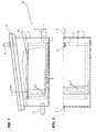
- a plate blast gas generator comprises a base container 1, which is substantially cuboid and which is closed at the top by a glass plate 2.
- the basic container consists of plates of material 1.4301, which are tightly welded together.
- the upper glass plate 2 is screwed to the base container 1. Between the upper edge of the base container 1 and the glass plate 2 is provided as a seal, an O-ring made of PTFE.
- the basic container In the basic container, vertical electrode plates 3 are arranged parallel to each other and spaced from each other. The electrode plates 3 are connected to each other alternately. They are also arranged in a meandering shape.
- the basic container is filled with water, in which there is an ion exchanger. The water level is designated 4.
- a water inlet 5 and a cable bushing for sensors and electrodes are provided in the basic container 1.
- a plastic insert 7 made of PE or PTFE is placed for holding the electrode plates, which may be bolted to the bottom of the base container.
- closable holes 8 are provided for the exchange of water in the bottom region of the basic container.
- a flange 9 for the gas extraction.
- a cover 10 is placed with a plastic fabric, which retains the ion exchanger.
- the electrode plates are made of material 1.4301. They are 1 mm thick and spaced at 3 mm. The connections of the electrode plates 3 are welded.
- the material of the electrode plates 3 may be made of platinum, platinum-plated platinum or a platinum-coated base material.
- Electrode plates 3 Between the electrode plates 3 is an acidic or alkaline ion exchanger.
- a base material which is in an ion bond or van der Waals bond with H + or OH-, ie a material which has to give up the originally present bond by confronting it with electrons or protons, thus becoming highly energetic and thus makes a significant contribution to water splitting.
- the normal cleavage energy necessary for water splitting can therefore be kept much lower.
- the input energy is thus only an active energy (starter energy).
- the base tank 5 water is supplied through the water inlet.
- the supply of electrical energy to the electrode plates 3 takes place through the cable bushing 6.
- the blast gas generated is drawn off via the flange 9.
- the blast gas withdrawn through the flange 9 is nascent blast gas. It will be in one of the in Fig. 3 to 5 shown container.
- Fig. 3 an explosion-proof container 11 is shown, which is filled with water 12, which forms a water level 13.
- a line 14 the detonated gas withdrawn from the container 1 is guided into the container 11.
- the line 14 terminates in the water 12 below the water level 13.
- the explosive gas flowing out of the end 15 of the line 14 forms 12 bubbles 16 in the water, which rise in the water 12 upwards.
- a piezoelectric igniter 17 which ignites the bubble gas located in the bubbles 16.
- the piezoelectric igniter 17 comprises two opposing electrodes 18, 19, which are interconnected by a bracket 20.
- the detonating gas ignited by the piezoelectric igniter 17 burns or explodes and releases its heat to the surrounding water 12, which is thereby heated.
- the process is conducted in such a way that the water 12 is not heated above the boiling point.
- the water 12 can be heated to 80 °.
- the water 12 is continuously supplied to the container 11 and discharged therefrom, as indicated by the double arrow 21.
- the piezoelectric igniter 17 is not arranged below, but above the water level 13.
- the piezoelectric igniter 17 is located above the end 15 of the conduit 14. Above the water level 13, the bubbles 16 open, and the detonating gas therein continues to rise upwards. It enters the region between the electrodes 18, 19 of the piezo igniter 13, where it is ignited. In this way, the piezo igniter 17 ignites the detonating gas, which is located above the water level 13.
- the resulting heat is transferred to the water 12.
- the water 12 is continuously supplied to the container 11 and discharged therefrom, as can be seen from the double arrow 21. In this way, the heat supplied to the water 12 can be removed and used outside of the container 11.
- the piezo igniter 17 is arranged below the water level 13. It is overarched by a dome 22, which is closed at the top and open at the bottom and into which the oxyhydrogen bubbles 16 ascend.
- the piezo igniter 17 is located in the region of the end 15 of the line 14.
- the dome 22 is configured areal and vaulted the piezoelectric igniter 17 in the manner of an inverted tub.
- the oxyhydrogen gas it is possible to first extract the oxyhydrogen gas from the container in which it is produced, for example by means of a vacuum pump, and to lead into a water-flow-through explosion-proof container 11.
- This container 11 can be continuously or discontinuously traversed by water.
- the oxyhydrogen may then be detonated either above the water level or under water to explode or burn.
- ignition and combustion or explosion under water pay attention to the size of the bubbles and the frequency of bubbles in terms of their formation and their ignition or combustion or explosion. It is also possible to burn the explosive gas in a submerged dome 18 or explode.
- Another possibility according to the invention is to burn or explode the oxyhydrogen in the container in which it is generated.
- the method can be performed in such a way that first hydrogen and oxygen are separated and then burned controlled or exploded.
- the oxyhydrogen could be separated by a membrane in hydrogen and oxygen, so that only burns hydrogen.
- the oxygen could be put to further use. However, a certain amount of oxygen is needed for the combustion of hydrogen.
Landscapes
- Engineering & Computer Science (AREA)
- Chemical & Material Sciences (AREA)
- Combustion & Propulsion (AREA)
- Mechanical Engineering (AREA)
- General Engineering & Computer Science (AREA)
- Electrolytic Production Of Non-Metals, Compounds, Apparatuses Therefor (AREA)
- Disintegrating Or Milling (AREA)
Abstract
Description
- Die Erfindung betrifft ein Verfahren zur Freisetzung des Energieinhaltes von Knallgas. Insbesondere betrifft die Erfindung ein Verfahren zur Freisetzung des Energieinhaltes von naszierendem bzw. originärem Knallgas. Die Erfindung betrifft ferner eine Vorrichtung zur Durchführung eines derartigen Verfahrens und einen Motor, der eine derartige Vorrichtung umfaßt.
- Aus der
DE 103 59 509 B4 ist ein Verfahren zur Herstellung von Knallgas bekannt, bei dem Wasser elektrolytisch behandelt wird. In dem Wasser ist ein lonenaustauscher vorhanden, dem Wasserstoff anhaftet. - Aufgabe der Erfindung ist es, ein verbessertes Verfahren und eine verbesserte Vorrichtung zur Freisetzung des Energieinhaltes von Knallgas vorzuschlagen.
- Erfindungsgemäß wird diese Aufgabe durch die Merkmale des Anspruchs 1 gelöst. Das Knallgas, bei dem es sich vorzugsweise um naszierendes (originäres) Knallgas handelt, wird in einem flüssigen oder gasförmigen oder festen Medium entzündet. Bei dem flüssigen Medium kann es sich insbesondere um flüssiges Wasser handeln. Das gasförmige Medium ist insbesondere Luft. Als festes Medium kann insbesondere ein poröses festes Medium verwendet werden. Das Knallgas kann brennen oder explodieren. Vorteilhaft ist es, wenn das Knallgas explodiert, da bei einer Explosion höhere Energien frei werden als bei einer Verbrennung.
- Vorteilhafte Weiterbildungen sind in den Unteransprüchen beschrieben.
- Die Entzündung des Knallgases kann durch eine Funkenstrecke erfolgen.
- Insbesondere kann die Entzündung des Knallgases durch einen Piezozünder oder ein sonstiges Piezoelement erfolgen.
- Nach einer weiteren vorteilhaften Weiterbildung wird das Knallgas dadurch erzeugt, daß eine Flüssigkeit elektrolytisch behandelt wird. Dabei ist es vorteilhaft, wenn in der Flüssigkeit, insbesondere Wasser, ein Ionenaustauscher vorhanden ist, dem das oder eines der herzustellenden Gase, insbesondere Wasserstoff und/oder Sauerstoff anhaftet.
- Die elektrolytische Behandlung der Flüssigkeit kann insbesondere nach der
DE 103 59 509 B4 durchgeführt werden. Bei diesem Verfahren wird Wasser elektrolytische behandelt, wobei in dem Wasser ein vorzugsweise gelförmiger Ionenaustauscher vorhanden ist, dem Wasserstoff, vorzugsweise in Ionenbindung, anhaftet. Bei dem Ionenaustauscher handelt es sich vorzugsweise um einen stark sauren, gelförmigen lonenaustauscher mit Sulfonsäuregruppen als Ankergruppen. Der lonenaustauscher hat die allgemeine chemische Formel R-SO3-H, wobei R eine Matrix, insbesondere eine vernetzte Polystyrol-Matrix bezeichnet, SO3 eine Sulfonsäure-Ankergruppe und H Wasserstoff. Auch die weiteren Einzelheiten aus derDE 103 59 509 B4 oder derDE 10 2006 07 272 B4 können durchgeführt werden. - Eine erfindungsgemäße Vorrichtung zur Durchführung des erfindungsgemäßen Verfahrens umfaßt einen Behälter mit einem Zulauf für Knallgas und einem Zünder zum Entzünden des Knallgases.
- Der erfindungsgemäße Motor, insbesondere für ein Fahrzeug, insbesondere für ein Kraftfahrzeug, umfaßt eine erfindungsgemäße Vorrichtung.
- Ein Ausführungsbeispiel der Erfindung wird nachstehend anhand der beigefügten Zeichnung im einzelnen erläutert. In der Zeichnung zeigt
- Fig. 1
- eine Vorrichtung zur Erzeugung von Knallgas in einer Seitenansicht,
- Fig. 2
- die Vorrichtung gemäß
Fig. 1 in einer Draufsicht, - Fig. 3
- eine Vorrichtung zum Entzünden von Knallgas mit einem Zünder,
- Fig. 4
- eine Abwandlung der Vorrichtung gemäß
Fig. 3 und - Fig. 5
- eine weitere Abwandlung der Vorrichtung gemäß
Fig. 3 und 4 . - Die in
Fig. 1 und 2 dargestellte Vorrichtung zur Erzeugung von Knallgas, die auch als Plattenknallgaserzeuger bezeichnet werden kann, umfaßt einen Grundbehälter 1, der im wesentlichen quaderförmig ist und der oben durch eine Glasplatte 2 verschlossen ist. Der Grundbehälter besteht aus Platten des Materials 1.4301, die dicht miteinander verschweißt sind. Die obere Glasplatte 2 ist mit dem Grundbehälter 1 verschraubt. Zwischen dem oberen Rand des Grundbehälters 1 und der Glasplatte 2 ist als Dichtung ein O-Ring aus PTFE vorgesehen. - In dem Grundbehälter sind vertikale Elektrodenplatten 3 parallel zueinander und im Abstand voneinander angeordnet. Die Elektrodenplatten 3 sind alternierend miteinander verbunden. Sie sind ferner in Mäanderform angeordnet. Der Grundbehälter ist mit Wasser gefüllt, in dem sich ein lonenaustauscher befindet. Der Wasserstand ist mit 4 bezeichnet. Im Grundbehälter 1 sind ein Wasserzulauf 5 und eine Kabeldurchführung für Sensoren und Elektroden vorgesehen. Auf den Boden des Grundbehälters 1 ist ein Kunststoffeinsatz 7 aus PE oder PTFE zum Halten der Elektrodenplatten aufgesetzt, der mit dem Boden des Grundbehälters verschraubt sein kann. Ferner sind im Bodenbereich des Grundbehälters verschließbare Bohrungen 8 für den Wasseraustausch vorgesehen.
- In der Glasplatte 2 befindet sich ein Flansch 9 für die Gasentnahme. Auf das obere Ende des Kunststoffeinsatzes 7 ist eine Abdeckung 10 mit einem Kunststoffgewebe aufgelegt, die den lonenaustauscher zurückhält.
- Die Elektrodenplatten bestehen aus dem Material 1.4301. Sie sind 1 mm dick und im Abstand von 3 mm angeordnet. Die Verbindungen der Elektrodenplatten 3 sind geschweißt. Das Material der Elektrodenplatten 3 kann aus Platin, aus platiniertem Platin oder aus einem platinbeschichteten Grundmaterial bestehen.
- Zwischen den Elektrodenplatten 3 befindet sich ein saurer oder alkalischer Ionenaustauscher. Es kann allerdings auch ein Grundmaterial, das mit H+ oder OH- in einer Ionenbindung oder van der Waal'schen Bindung steht, Verwendung finden, also ein Material, das durch Konfrontation mit Elektronen oder Protonen die ursprünglich vorhandene Bindung aufgeben muß, somit hochenergetisch wird und damit einen erheblichen Beitrag zur Wasserspaltung liefert. Die normale Spaltungsenergie, die zur Wasserspaltung notwendig ist, kann deshalb wesentlich geringer gehalten werden. Die Eingangsenergie ist somit nur noch eine Wirkenergie (Starterenergie).
- Im Betrieb wird dem Grundbehälter durch den Wasserzulauf 5 Wasser zugeführt. Die Zuführung elektrischer Energie zu den Elektrodenplatten 3 erfolgt durch die Kabeldurchführung 6. Das erzeugte Knallgas wird über den Flansch 9 abgezogen.
- Bei dem durch den Flansch 9 abgezogenen Knallgas handelt es sich um naszierendes Knallgas. Es wird in einen der in
Fig. 3 bis 5 gezeigten Behälter geleitet. - In
Fig. 3 ist ein explosionsgeschützter Behälter 11 dargestellt, der mit Wasser 12 gefüllt ist, das einen Wasserspiegel 13 ausbildet. Durch eine Leitung 14 wird das aus dem Behälter 1 abgezogene Knallgas in den Behälter 11 geführt. Die Leitung 14 endet im Wasser 12 unterhalb des Wasserspiegels 13. Das aus dem Ende 15 der Leitung 14 strömende Knallgas bildet im Wasser 12 Blasen 16, die im Wasser 12 nach oben steigen. Über dem Ende 15 der Leitung 14 befindet sich ein Piezozünder 17, der das in den Blasen 16 befindliche Knallgas entzündet. Der Piezozünder 17 umfaßt zwei einander gegenüberliegende Elektroden 18, 19, die durch einen Bügel 20 miteinander verbunden sind. Das durch den Piezozünder 17 entzündete Knallgas verbrennt oder explodiert und gibt seine Wärme an das umgebende Wasser 12 ab, das dadurch aufgeheizt wird. - Das Verfahren wird in der Weise geführt, daß das Wasser 12 nicht über den Siedepunkt hinaus erhitzt wird. Beispielsweise kann das Wasser 12 auf 80° erhitzt werden. Es ist allerdings auch möglich, durch einen höheren Druck höhere Temperaturen zu erreichen. Das Wasser 12 wird laufend dem Behälter 11 zugeführt und aus diesem abgeführt, wie durch den Doppelpfeil 21 angedeutet.
- Die in
Fig. 4 gezeigte Ausführungsform unterscheidet sich von derjenigen nachFig. 3 dadurch, daß der Piezozünder 17 nicht unter, sondern über dem Wasserspiegel 13 angeordnet ist. Der Piezozünder 17 befindet sich oberhalb des Endes 15 der Leitung 14. Über dem Wasserspiegel 13 öffnen sich die Blasen 16, und das darin befindliche Knallgas steigt weiter nach oben. Es gelangt in den Bereich zwischen den Elektroden 18, 19 des Piezozünders 13, wo es entzündet wird. Auf diese Weise zündet der Piezozünder 17 das Knallgas, das sich über dem Wasserspiegel 13 befindet. Die dadurch entstandene Wärme wird auf das Wasser 12 übertragen. Das Wasser 12 wird laufend dem Behälter 11 zugeführt und aus diesem abgeführt, wie aus dem Doppelpfeil 21 ersichtlich. Auf diese Weise kann die dem Wasser 12 zugeführte Wärme abtransportiert und außerhalb des Behälters 11 genutzt werden. - Bei der Abwandlung nach
Fig. 5 ist der Piezozünder 17 unter dem Wasserspiegel 13 angeordnet. Er wird von einem Dom 22 überwölbt, der oben geschlossen und unten offen ist und in den die Knallgas-Blasen 16 aufsteigen. Der Piezozünder 17 befindet sich im Bereich des Endes 15 der Leitung 14. Der Dom 22 ist flächig ausgestaltet und überwölbt den Piezozünder 17 nach Art einer umgedrehten Wanne. - Gemäß der Erfindung besteht sowohl die Möglichkeit, das Knallgas zunächst aus dem Behälter, in dem es erzeugt wird, abzuziehen, beispielsweise mittels einer Vakuumpumpe, und in einen von Wasser durchströmten explosionsgesicherten Behälter 11 zu leiten. Dieser Behälter 11 kann kontinuierlich oder diskontinuierlich von Wasser durchströmt werden. Das Knallgas kann dann mittels Zündung entweder über dem Wasserspiegel oder unter Wasser zur Explosion oder Verbrennung gebracht werden. Bei einer Zündung und Verbrennung oder Explosion unter Wasser ist auf die Größe der Blasen und auf die Blasenhäufigkeit hinsichtlich ihrer Entstehung und hinsichtlich ihrer Zündung bzw. Verbrennung bzw. Explosion zu achten. Es ist auch möglich, das Knallgas in einem unter Wasser befindlichen Dom 18 verbrennen oder explodieren zu lassen.
- Eine weitere Möglichkeit gemäß der Erfindung besteht darin, das Knallgas in dem Behälter zu verbrennen oder explodieren zu lassen, in dem es erzeugt wird. Insbesondere kann das Verfahren in der Weise geführt werden, daß zunächst Wasserstoff und Sauerstoff getrennt werden und anschließend kontrolliert verbrannt oder zur Explosion gebracht werden.
- Das Knallgas könnte durch eine Membran in Wasserstoff und Sauerstoff getrennt werden, so daß nur Wasserstoff verbrennt. Der Sauerstoff könnte einer weiteren Verwendung zugeführt werden. Ein gewisser Anteil von Sauerstoff ist allerdings für die Verbrennung des Wasserstoffes nötig.
Claims (7)
- Verfahren zur Freisetzung des Energieinhaltes von Knallgas,
dadurch gekennzeichnet,
daß das Knallgas in einem flüssigen oder gasförmigen oder festen Medium entzündet (17) wird. - Verfahren nach Anspruch 1, dadurch gekennzeichnet, daß die Entzündung durch eine Funkenstrecke erfolgt.
- Verfahren nach Anspruch 1 oder 2, dadurch gekennzeichnet, daß die Entzündung durch einen Piezozünder (17) erfolgt.
- Verfahren nach einem der vorhergehenden Ansprüche, dadurch gekennzeichnet, daß das Knallgas dadurch erzeugt wird, daß eine Flüssigkeit elektrolytisch behandelt wird.
- Verfahren nach Anspruch 4, dadurch gekennzeichnet, daß in der Flüssigkeit, insbesondere Wasser (12), ein lonenaustauscher vorhanden ist, dem das oder eines der herzustellenden Gase, insbesondere Wasserstoff und/oder Sauerstoff, anhaftet.
- Vorrichtung zur Durchführung des Verfahrens nach einem der vorhergehenden Ansprüche, umfassend: einen Behälter (11), einen Zulauf (15) für Knallgas und einen Zünder, insbesondere einen Piezozünder (17), zum Entzünden des Knallgases.
- Motor, insbesondere für ein Fahrzeug, insbesondere für ein Kraftfahrzeug, gekennzeichnet durch eine Vorrichtung nach Anspruch 6.
Applications Claiming Priority (1)
| Application Number | Priority Date | Filing Date | Title |
|---|---|---|---|
| DE102008038155A DE102008038155A1 (de) | 2008-08-18 | 2008-08-18 | Verfahren zur Freisetzung des Energieinhaltes von Knallgas |
Publications (3)
| Publication Number | Publication Date |
|---|---|
| EP2157310A2 true EP2157310A2 (de) | 2010-02-24 |
| EP2157310A3 EP2157310A3 (de) | 2014-02-26 |
| EP2157310B1 EP2157310B1 (de) | 2016-05-04 |
Family
ID=41279458
Family Applications (1)
| Application Number | Title | Priority Date | Filing Date |
|---|---|---|---|
| EP09006882.6A Not-in-force EP2157310B1 (de) | 2008-08-18 | 2009-05-22 | Verfahren zur Freisetzung des Energieinhaltes von Knallgas |
Country Status (2)
| Country | Link |
|---|---|
| EP (1) | EP2157310B1 (de) |
| DE (1) | DE102008038155A1 (de) |
Cited By (2)
| Publication number | Priority date | Publication date | Assignee | Title |
|---|---|---|---|---|
| DE102016000791A1 (de) | 2016-01-26 | 2017-07-27 | Norbert Pautz | Verfahren und Vorrichtung einer Energiegewinnung bei einer Elektrokoagulation der Abwasserreinigung, durch Nutzung, bei dem Verfahren entstehende Wasserstoff-Sauerstoff-Gasmischung |
| CN109884118A (zh) * | 2019-04-02 | 2019-06-14 | 中国工程物理研究院化工材料研究所 | 一种基于升温法的爆容自动测试系统及方法 |
Citations (2)
| Publication number | Priority date | Publication date | Assignee | Title |
|---|---|---|---|---|
| DE10359509B4 (de) | 2003-11-28 | 2005-12-29 | Roiner, Franz, Prof. | Verfahren zur Herstellung eines oder mehrerer Gase |
| DE102006007272A1 (de) | 2006-02-16 | 2007-09-06 | Franz Prof. Roiner | Verfahren und Vorrichtung zur Herstellung eines oder mehrerer Gase und/oder zur Erzeugung und/oder Speicherung von elektrischer Energie |
Family Cites Families (9)
| Publication number | Priority date | Publication date | Assignee | Title |
|---|---|---|---|---|
| GB367829A (en) * | 1930-11-19 | 1932-02-19 | Robert Henry Davis | Improvements in ignition devices for oxy-acetylene and like cutting apparatus |
| GB491678A (en) * | 1936-11-02 | 1938-09-07 | Silesia Ver Chemischeb Fabrike | Improvements in immersion or under-water burners |
| EP0202262B1 (de) * | 1984-11-16 | 1989-10-04 | BALSIGER, Benno | Vorrichtung zur aktivierung des verbrennungsvorganges |
| JPS62272008A (ja) * | 1986-05-20 | 1987-11-26 | Masahiro Aiura | 水中バ−ナ− |
| US5370528A (en) * | 1992-08-03 | 1994-12-06 | Martin Marietta Energy Systems, Inc. | Submergible torch for treating waste solutions and method thereof |
| JP3669600B2 (ja) * | 1994-12-29 | 2005-07-06 | 本田技研工業株式会社 | 内燃機関の点火装置 |
| US6289868B1 (en) * | 2000-02-11 | 2001-09-18 | Michael E. Jayne | Plasma ignition for direct injected internal combustion engines |
| US20050126155A1 (en) * | 2000-09-11 | 2005-06-16 | Petur Thordarson | Hydrogen motor |
| US7340893B1 (en) * | 2004-05-14 | 2008-03-11 | Rowan James A | Steam generator system |
-
2008
- 2008-08-18 DE DE102008038155A patent/DE102008038155A1/de not_active Withdrawn
-
2009
- 2009-05-22 EP EP09006882.6A patent/EP2157310B1/de not_active Not-in-force
Patent Citations (2)
| Publication number | Priority date | Publication date | Assignee | Title |
|---|---|---|---|---|
| DE10359509B4 (de) | 2003-11-28 | 2005-12-29 | Roiner, Franz, Prof. | Verfahren zur Herstellung eines oder mehrerer Gase |
| DE102006007272A1 (de) | 2006-02-16 | 2007-09-06 | Franz Prof. Roiner | Verfahren und Vorrichtung zur Herstellung eines oder mehrerer Gase und/oder zur Erzeugung und/oder Speicherung von elektrischer Energie |
Cited By (3)
| Publication number | Priority date | Publication date | Assignee | Title |
|---|---|---|---|---|
| DE102016000791A1 (de) | 2016-01-26 | 2017-07-27 | Norbert Pautz | Verfahren und Vorrichtung einer Energiegewinnung bei einer Elektrokoagulation der Abwasserreinigung, durch Nutzung, bei dem Verfahren entstehende Wasserstoff-Sauerstoff-Gasmischung |
| CN109884118A (zh) * | 2019-04-02 | 2019-06-14 | 中国工程物理研究院化工材料研究所 | 一种基于升温法的爆容自动测试系统及方法 |
| CN109884118B (zh) * | 2019-04-02 | 2023-08-29 | 中国工程物理研究院化工材料研究所 | 一种基于升温法的爆容自动测试系统及方法 |
Also Published As
| Publication number | Publication date |
|---|---|
| EP2157310A3 (de) | 2014-02-26 |
| DE102008038155A1 (de) | 2010-02-25 |
| EP2157310B1 (de) | 2016-05-04 |
Similar Documents
| Publication | Publication Date | Title |
|---|---|---|
| DE2810528C3 (de) | Verfahren und Vorrichtung zur elektrolytischen Erzeugung von Wasserstoff und Sauerstoff | |
| EP3380713B1 (de) | Verfahren zum betreiben einer verbrennungskraftmaschine mit einem der verbrennungsluft zugeführten, durch wasserelektrolyse erzeugten gasgemisch sowie anordnung und eletrolysegerät zur durchführung des verfahrens | |
| US7793621B2 (en) | Alternative fuel engine | |
| DE3490295T1 (de) | Wasserstoffmaschine | |
| WO2007138363A1 (en) | Method and device for purifying and enrichment of hydrocarbon material | |
| EP2157310B1 (de) | Verfahren zur Freisetzung des Energieinhaltes von Knallgas | |
| DE102012006086B4 (de) | Verfahren zur Herstellung eines Gasgemisches | |
| US4124463A (en) | Electrolytic cell | |
| CN1382200A (zh) | 改进烃类燃料的方法及改进烃类燃料的装置 | |
| DE102010049792B4 (de) | Kleinkraftwerk sowie Verfahren und Vorrichtung zur Gewinnung von hochreinem Wasserstoff | |
| DE102012222105A1 (de) | Brennstoffzellenanordnung und Verfahren zum Betrieb der Brennstoffzellenanordnung | |
| WO2013159755A1 (en) | Generator assembly with internal combustion engine having energy efficiency increasing means | |
| DE19523939C2 (de) | Anlage zur Speicherung und Nutzbarmachung von Solar-, Wind- und/oder Wasserkraftenergie | |
| DE102015102998A1 (de) | Verfahren und Anordnung zur Durchführung des Verfahrens zum elektrochemischen Verbinden von Wasserstoff und der Sauerstoff als Elektrolysegas mit zumindest einem an sich bekannten Brenngas als Trägergas zu einem verbundenen Gas | |
| DE102006007773A1 (de) | Anordnung und Verfahren zum Spalten von Wasser | |
| US20090092540A1 (en) | Method and apparatus of modifying bond angles of molecules | |
| EP3865455A1 (de) | Verfahren und vorrichtung zur gewinnung von browns-gas und/oder sauerstoff und wasserstoff, insbesondere für verbrennungsmotoren, heizungsbrenner oder brennstoffzellen | |
| DE102006030449A1 (de) | Verfahren zum Speichern von Wasserstoff | |
| JP2017155244A (ja) | 加水燃料の製造方法及び製造装置 | |
| DE19528681C2 (de) | Verfahren zur Speicherung und Nutzbarmachung von Solar-, Wind- oder Wasserkraftenergie | |
| DE345048C (de) | ||
| DE102006007272B4 (de) | Verfahren und Vorrichtung zur Herstellung eines oder mehrerer Gase und/oder zur Speicherung von elektrischer Energie | |
| CN210559873U (zh) | 一种精细化工生产用废水回收处理装置 | |
| DE472398C (de) | Zur elektrolytischen Gewinnung von Wasserstoff und Sauerstoff bestimmter Elektrolysierapparat | |
| DE406979C (de) | Vorrichtung zur Erzeugung eines gasfoermigen Brennstoffs |
Legal Events
| Date | Code | Title | Description |
|---|---|---|---|
| PUAI | Public reference made under article 153(3) epc to a published international application that has entered the european phase |
Free format text: ORIGINAL CODE: 0009012 |
|
| AK | Designated contracting states |
Kind code of ref document: A2 Designated state(s): AT BE BG CH CY CZ DE DK EE ES FI FR GB GR HR HU IE IS IT LI LT LU LV MC MK MT NL NO PL PT RO SE SI SK TR |
|
| AX | Request for extension of the european patent |
Extension state: AL BA RS |
|
| REG | Reference to a national code |
Ref country code: DE Ref legal event code: R079 Ref document number: 502009012508 Country of ref document: DE Free format text: PREVIOUS MAIN CLASS: F02M0025120000 Ipc: F23D0014440000 |
|
| PUAL | Search report despatched |
Free format text: ORIGINAL CODE: 0009013 |
|
| AK | Designated contracting states |
Kind code of ref document: A3 Designated state(s): AT BE BG CH CY CZ DE DK EE ES FI FR GB GR HR HU IE IS IT LI LT LU LV MC MK MT NL NO PL PT RO SE SI SK TR |
|
| AX | Request for extension of the european patent |
Extension state: AL BA RS |
|
| RIC1 | Information provided on ipc code assigned before grant |
Ipc: F23Q 2/28 20060101ALI20140122BHEP Ipc: F02M 25/12 20060101ALI20140122BHEP Ipc: F24H 1/10 20060101ALI20140122BHEP Ipc: F02P 3/12 20060101ALI20140122BHEP Ipc: F23D 14/44 20060101AFI20140122BHEP |
|
| 17P | Request for examination filed |
Effective date: 20140825 |
|
| RBV | Designated contracting states (corrected) |
Designated state(s): AT BE BG CH CY CZ DE DK EE ES FI FR GB GR HR HU IE IS IT LI LT LU LV MC MK MT NL NO PL PT RO SE SI SK TR |
|
| 17Q | First examination report despatched |
Effective date: 20141219 |
|
| GRAP | Despatch of communication of intention to grant a patent |
Free format text: ORIGINAL CODE: EPIDOSNIGR1 |
|
| INTG | Intention to grant announced |
Effective date: 20151123 |
|
| GRAS | Grant fee paid |
Free format text: ORIGINAL CODE: EPIDOSNIGR3 |
|
| GRAA | (expected) grant |
Free format text: ORIGINAL CODE: 0009210 |
|
| AK | Designated contracting states |
Kind code of ref document: B1 Designated state(s): AT BE BG CH CY CZ DE DK EE ES FI FR GB GR HR HU IE IS IT LI LT LU LV MC MK MT NL NO PL PT RO SE SI SK TR |
|
| REG | Reference to a national code |
Ref country code: GB Ref legal event code: FG4D Free format text: NOT ENGLISH |
|
| REG | Reference to a national code |
Ref country code: CH Ref legal event code: EP |
|
| REG | Reference to a national code |
Ref country code: AT Ref legal event code: REF Ref document number: 797254 Country of ref document: AT Kind code of ref document: T Effective date: 20160515 |
|
| REG | Reference to a national code |
Ref country code: IE Ref legal event code: FG4D Free format text: LANGUAGE OF EP DOCUMENT: GERMAN |
|
| REG | Reference to a national code |
Ref country code: DE Ref legal event code: R096 Ref document number: 502009012508 Country of ref document: DE |
|
| REG | Reference to a national code |
Ref country code: NL Ref legal event code: MP Effective date: 20160504 |
|
| REG | Reference to a national code |
Ref country code: LT Ref legal event code: MG4D |
|
| PG25 | Lapsed in a contracting state [announced via postgrant information from national office to epo] |
Ref country code: NL Free format text: LAPSE BECAUSE OF FAILURE TO SUBMIT A TRANSLATION OF THE DESCRIPTION OR TO PAY THE FEE WITHIN THE PRESCRIBED TIME-LIMIT Effective date: 20160504 Ref country code: FI Free format text: LAPSE BECAUSE OF FAILURE TO SUBMIT A TRANSLATION OF THE DESCRIPTION OR TO PAY THE FEE WITHIN THE PRESCRIBED TIME-LIMIT Effective date: 20160504 Ref country code: NO Free format text: LAPSE BECAUSE OF FAILURE TO SUBMIT A TRANSLATION OF THE DESCRIPTION OR TO PAY THE FEE WITHIN THE PRESCRIBED TIME-LIMIT Effective date: 20160804 Ref country code: LT Free format text: LAPSE BECAUSE OF FAILURE TO SUBMIT A TRANSLATION OF THE DESCRIPTION OR TO PAY THE FEE WITHIN THE PRESCRIBED TIME-LIMIT Effective date: 20160504 |
|
| PG25 | Lapsed in a contracting state [announced via postgrant information from national office to epo] |
Ref country code: HR Free format text: LAPSE BECAUSE OF FAILURE TO SUBMIT A TRANSLATION OF THE DESCRIPTION OR TO PAY THE FEE WITHIN THE PRESCRIBED TIME-LIMIT Effective date: 20160504 Ref country code: SE Free format text: LAPSE BECAUSE OF FAILURE TO SUBMIT A TRANSLATION OF THE DESCRIPTION OR TO PAY THE FEE WITHIN THE PRESCRIBED TIME-LIMIT Effective date: 20160504 Ref country code: LV Free format text: LAPSE BECAUSE OF FAILURE TO SUBMIT A TRANSLATION OF THE DESCRIPTION OR TO PAY THE FEE WITHIN THE PRESCRIBED TIME-LIMIT Effective date: 20160504 Ref country code: GR Free format text: LAPSE BECAUSE OF FAILURE TO SUBMIT A TRANSLATION OF THE DESCRIPTION OR TO PAY THE FEE WITHIN THE PRESCRIBED TIME-LIMIT Effective date: 20160805 Ref country code: ES Free format text: LAPSE BECAUSE OF FAILURE TO SUBMIT A TRANSLATION OF THE DESCRIPTION OR TO PAY THE FEE WITHIN THE PRESCRIBED TIME-LIMIT Effective date: 20160504 Ref country code: PT Free format text: LAPSE BECAUSE OF FAILURE TO SUBMIT A TRANSLATION OF THE DESCRIPTION OR TO PAY THE FEE WITHIN THE PRESCRIBED TIME-LIMIT Effective date: 20160905 |
|
| REG | Reference to a national code |
Ref country code: DE Ref legal event code: R119 Ref document number: 502009012508 Country of ref document: DE |
|
| PG25 | Lapsed in a contracting state [announced via postgrant information from national office to epo] |
Ref country code: BE Free format text: LAPSE BECAUSE OF NON-PAYMENT OF DUE FEES Effective date: 20160531 Ref country code: IT Free format text: LAPSE BECAUSE OF FAILURE TO SUBMIT A TRANSLATION OF THE DESCRIPTION OR TO PAY THE FEE WITHIN THE PRESCRIBED TIME-LIMIT Effective date: 20160504 |
|
| REG | Reference to a national code |
Ref country code: CH Ref legal event code: PL |
|
| PG25 | Lapsed in a contracting state [announced via postgrant information from national office to epo] |
Ref country code: EE Free format text: LAPSE BECAUSE OF FAILURE TO SUBMIT A TRANSLATION OF THE DESCRIPTION OR TO PAY THE FEE WITHIN THE PRESCRIBED TIME-LIMIT Effective date: 20160504 Ref country code: CZ Free format text: LAPSE BECAUSE OF FAILURE TO SUBMIT A TRANSLATION OF THE DESCRIPTION OR TO PAY THE FEE WITHIN THE PRESCRIBED TIME-LIMIT Effective date: 20160504 Ref country code: LI Free format text: LAPSE BECAUSE OF NON-PAYMENT OF DUE FEES Effective date: 20160531 Ref country code: DK Free format text: LAPSE BECAUSE OF FAILURE TO SUBMIT A TRANSLATION OF THE DESCRIPTION OR TO PAY THE FEE WITHIN THE PRESCRIBED TIME-LIMIT Effective date: 20160504 Ref country code: CH Free format text: LAPSE BECAUSE OF NON-PAYMENT OF DUE FEES Effective date: 20160531 Ref country code: RO Free format text: LAPSE BECAUSE OF FAILURE TO SUBMIT A TRANSLATION OF THE DESCRIPTION OR TO PAY THE FEE WITHIN THE PRESCRIBED TIME-LIMIT Effective date: 20160504 Ref country code: SK Free format text: LAPSE BECAUSE OF FAILURE TO SUBMIT A TRANSLATION OF THE DESCRIPTION OR TO PAY THE FEE WITHIN THE PRESCRIBED TIME-LIMIT Effective date: 20160504 |
|
| REG | Reference to a national code |
Ref country code: IE Ref legal event code: MM4A |
|
| PG25 | Lapsed in a contracting state [announced via postgrant information from national office to epo] |
Ref country code: PL Free format text: LAPSE BECAUSE OF FAILURE TO SUBMIT A TRANSLATION OF THE DESCRIPTION OR TO PAY THE FEE WITHIN THE PRESCRIBED TIME-LIMIT Effective date: 20160504 |
|
| PLBE | No opposition filed within time limit |
Free format text: ORIGINAL CODE: 0009261 |
|
| STAA | Information on the status of an ep patent application or granted ep patent |
Free format text: STATUS: NO OPPOSITION FILED WITHIN TIME LIMIT |
|
| PG25 | Lapsed in a contracting state [announced via postgrant information from national office to epo] |
Ref country code: MC Free format text: LAPSE BECAUSE OF FAILURE TO SUBMIT A TRANSLATION OF THE DESCRIPTION OR TO PAY THE FEE WITHIN THE PRESCRIBED TIME-LIMIT Effective date: 20160504 |
|
| REG | Reference to a national code |
Ref country code: FR Ref legal event code: ST Effective date: 20170306 |
|
| 26N | No opposition filed |
Effective date: 20170207 |
|
| GBPC | Gb: european patent ceased through non-payment of renewal fee |
Effective date: 20160804 |
|
| PG25 | Lapsed in a contracting state [announced via postgrant information from national office to epo] |
Ref country code: DE Free format text: LAPSE BECAUSE OF NON-PAYMENT OF DUE FEES Effective date: 20161201 Ref country code: FR Free format text: LAPSE BECAUSE OF NON-PAYMENT OF DUE FEES Effective date: 20160704 |
|
| PG25 | Lapsed in a contracting state [announced via postgrant information from national office to epo] |
Ref country code: SI Free format text: LAPSE BECAUSE OF FAILURE TO SUBMIT A TRANSLATION OF THE DESCRIPTION OR TO PAY THE FEE WITHIN THE PRESCRIBED TIME-LIMIT Effective date: 20160504 Ref country code: IE Free format text: LAPSE BECAUSE OF NON-PAYMENT OF DUE FEES Effective date: 20160522 |
|
| REG | Reference to a national code |
Ref country code: AT Ref legal event code: MM01 Ref document number: 797254 Country of ref document: AT Kind code of ref document: T Effective date: 20160522 |
|
| PG25 | Lapsed in a contracting state [announced via postgrant information from national office to epo] |
Ref country code: GB Free format text: LAPSE BECAUSE OF NON-PAYMENT OF DUE FEES Effective date: 20160804 |
|
| PG25 | Lapsed in a contracting state [announced via postgrant information from national office to epo] |
Ref country code: AT Free format text: LAPSE BECAUSE OF NON-PAYMENT OF DUE FEES Effective date: 20160522 |
|
| PG25 | Lapsed in a contracting state [announced via postgrant information from national office to epo] |
Ref country code: CY Free format text: LAPSE BECAUSE OF FAILURE TO SUBMIT A TRANSLATION OF THE DESCRIPTION OR TO PAY THE FEE WITHIN THE PRESCRIBED TIME-LIMIT Effective date: 20160504 Ref country code: HU Free format text: LAPSE BECAUSE OF FAILURE TO SUBMIT A TRANSLATION OF THE DESCRIPTION OR TO PAY THE FEE WITHIN THE PRESCRIBED TIME-LIMIT; INVALID AB INITIO Effective date: 20090522 |
|
| PG25 | Lapsed in a contracting state [announced via postgrant information from national office to epo] |
Ref country code: LU Free format text: LAPSE BECAUSE OF NON-PAYMENT OF DUE FEES Effective date: 20160522 Ref country code: TR Free format text: LAPSE BECAUSE OF FAILURE TO SUBMIT A TRANSLATION OF THE DESCRIPTION OR TO PAY THE FEE WITHIN THE PRESCRIBED TIME-LIMIT Effective date: 20160504 Ref country code: MT Free format text: LAPSE BECAUSE OF FAILURE TO SUBMIT A TRANSLATION OF THE DESCRIPTION OR TO PAY THE FEE WITHIN THE PRESCRIBED TIME-LIMIT Effective date: 20160504 Ref country code: MK Free format text: LAPSE BECAUSE OF FAILURE TO SUBMIT A TRANSLATION OF THE DESCRIPTION OR TO PAY THE FEE WITHIN THE PRESCRIBED TIME-LIMIT Effective date: 20160504 Ref country code: IS Free format text: LAPSE BECAUSE OF FAILURE TO SUBMIT A TRANSLATION OF THE DESCRIPTION OR TO PAY THE FEE WITHIN THE PRESCRIBED TIME-LIMIT Effective date: 20160504 |
|
| PG25 | Lapsed in a contracting state [announced via postgrant information from national office to epo] |
Ref country code: BG Free format text: LAPSE BECAUSE OF FAILURE TO SUBMIT A TRANSLATION OF THE DESCRIPTION OR TO PAY THE FEE WITHIN THE PRESCRIBED TIME-LIMIT Effective date: 20160504 |