EP2157249A2 - Drainage fittings with smell lock - Google Patents
Drainage fittings with smell lock Download PDFInfo
- Publication number
- EP2157249A2 EP2157249A2 EP09168394A EP09168394A EP2157249A2 EP 2157249 A2 EP2157249 A2 EP 2157249A2 EP 09168394 A EP09168394 A EP 09168394A EP 09168394 A EP09168394 A EP 09168394A EP 2157249 A2 EP2157249 A2 EP 2157249A2
- Authority
- EP
- European Patent Office
- Prior art keywords
- dip tube
- nozzle
- housing
- elevation
- volume
- Prior art date
- Legal status (The legal status is an assumption and is not a legal conclusion. Google has not performed a legal analysis and makes no representation as to the accuracy of the status listed.)
- Granted
Links
- 230000008859 change Effects 0.000 claims abstract description 6
- XLYOFNOQVPJJNP-UHFFFAOYSA-N water Substances O XLYOFNOQVPJJNP-UHFFFAOYSA-N 0.000 claims description 67
- 230000004888 barrier function Effects 0.000 claims description 14
- 230000007423 decrease Effects 0.000 claims description 7
- 230000009467 reduction Effects 0.000 claims description 4
- 238000007654 immersion Methods 0.000 abstract description 8
- 238000010276 construction Methods 0.000 abstract description 3
- 238000007789 sealing Methods 0.000 description 39
- 230000006870 function Effects 0.000 description 2
- 108010023321 Factor VII Proteins 0.000 description 1
- 239000007789 gas Substances 0.000 description 1
- 230000006872 improvement Effects 0.000 description 1
- 239000012535 impurity Substances 0.000 description 1
- 238000009434 installation Methods 0.000 description 1
- 230000007257 malfunction Effects 0.000 description 1
- 230000000717 retained effect Effects 0.000 description 1
Images


Classifications
-
- E—FIXED CONSTRUCTIONS
- E03—WATER SUPPLY; SEWERAGE
- E03F—SEWERS; CESSPOOLS
- E03F5/00—Sewerage structures
- E03F5/04—Gullies inlets, road sinks, floor drains with or without odour seals or sediment traps
- E03F5/0407—Floor drains for indoor use
- E03F5/0408—Floor drains for indoor use specially adapted for showers
-
- E—FIXED CONSTRUCTIONS
- E03—WATER SUPPLY; SEWERAGE
- E03F—SEWERS; CESSPOOLS
- E03F5/00—Sewerage structures
- E03F5/04—Gullies inlets, road sinks, floor drains with or without odour seals or sediment traps
- E03F2005/0416—Gullies inlets, road sinks, floor drains with or without odour seals or sediment traps with an odour seal
- E03F2005/0418—Gullies inlets, road sinks, floor drains with or without odour seals or sediment traps with an odour seal in the form of a bell siphon
Abstract
Description
Die Erfindung betrifft eine Ablaufarmatur mit Geruchverschluss mit einem einen Stutzen für den Anschluss an ein Leitungssystem aufweisenden Gehäuse, welches eine sich von einem Ablauf zu einem Auslauf erstreckende Gehäusekammer mit einem Gehäusegrund und Gehäuseseitenwänden bildet, und mit einem sich in die Gehäusekammer erstreckenden Tauchrohr, welches vom Gehäusegrund und den Gehäuseseitenwänden beabstandet ist und ein Reservoirvolumen begrenzt,
wobei der Stutzen einen Stutzenanschlussabschnitt aufweist, der das Innere des Stutzens mit der übrigen Gehäusekammer verbindet und einen Teil des Reservoirvolumens bildet, und wobei der Geruchverschluss mittels in dem Tauchrohr und in dem Reservoirvolumen vorgehaltenem Sperrwasser bewirkt wird.The invention relates to a drain fitting with odor trap with a connecting piece for connection to a conduit having housing, which forms a extending from a drain to a spout housing chamber with a housing base and housing side walls, and with a extending into the housing chamber dip tube, which from Housing base and the housing side walls is spaced and limits a reservoir volume,
wherein the nozzle has a nozzle connection portion which connects the interior of the nozzle with the rest of the housing chamber and forms part of the reservoir volume, and wherein the odor trap is effected by means of barrier water held in the dip tube and in the reservoir volume.
Ablaufarmaturen mit Geruchverschluss sind bereits im Stand der Technik bekannt. Die
Es sind auch Ablaufarmaturen ohne Kugel bekannt, die wie die eingangs beschriebene Ablaufarmatur, von der die Erfindung ausgeht, ein Gehäuse mit einem Stutzen zum Anschluss an ein Leitungssystem sowie mit einem sich in die Gehäusekammer erstreckenden Tauchrohr aufweisen, wobei einem Unterdruck im Leitungssystem wenn überhaupt nur dadurch entgegengewirkt wird, dass ein besonders hoher Sperrwasserstand (auch Sperrwasserniveau genannt) vorgesehen ist. Dadurch hat die Ablaufarmatur eine sehr große Bauhöhe und kann folglich insbesondere nicht unter flachen Duschwannen eingesetzt werden. Im Übrigen wird das Sperrwasser bei einem relativ großen Unterdruck im Leitungssystem oder bei mehreren aufeinanderfolgenden Störungen, die einen Unterdruck zur Folge haben, vollständig aus der Gehäusekammer abgezogen. Eine solche Ablaufarmatur ist beispielsweise aus der
Es ist daher die Aufgabe der vorliegenden Erfindung, eine Ablaufarmatur anzugeben, welche auch bei einem geringen Bauraum einen Geruchverschluss zuverlässig gewährleistet.It is therefore an object of the present invention to provide a drain fitting which reliably ensures odor trap even with a small space.
Die Aufgabe wird bei einer Ablaufarmatur mit Geruchverschluss nach dem Oberbegriff des Patentanspruchs 1 dadurch gelöst, dass als ein Konstruktionselement, welches eine Änderung des Strömungsverhaltens in einem vom Innern des Tauchrohrs zum Stutzenanschlussabschnitt führenden Strömungskanal bewirkt, der Boden des Stutzens eine sich von einer ersten Seitenwand zu einer gegenüberliegenden zweiten Seitenwand des Stutzens erstreckende Erhebung mit einem Höhenversatz aufweist, die den Strömungskanal verengt und im Stutzenanschlussabschnitt das Reservoirvolumen zum Auslauf hin begrenzt.The object is achieved in a drain fitting with odor trap according to the preamble of
Durch Vorsehen einer Erhebung wird bei der erfindungsgemäßen Ablaufarmatur eine sogenannte Sperrwasserbarriere gebildet, die einerseits bewirkt, dass sich das Sperrwasser bei ausgeglichenen Druckverhältnissen in der Gehäusekammer nicht über den Stutzenanschlussabschnitt hinaus verteilt, sondern durch die Erhebung zurückgehalten wird. Durch die Erhebung wird also eine Möglichkeit geschaffen, durch die auch im Stutzenanschlussabschnitt Sperrwasser stehen bzw. gespeichert werden kann, wobei der tiefste Punkt der Erhebung die maximale Sperrwasserhöhe (das maximale Sperrwasserniveau) im Reservoirvolumen definiert. Durch die Erhebung kann also auch ein Teil des Stutzens, nämlich der Stutzenanschlussabschnitt, zur Speicherung von Sperrwasser und damit als Zusatzspeicher genutzt werden, wodurch die Bauhöhe der Ablaufarmatur gegenüber dem Stand der Technik reduziert werden kann.By providing a survey a so-called barrier water barrier is formed in the drain fitting according to the invention, on the one hand causes the sealing water is not distributed at balanced pressure conditions in the housing chamber over the nozzle connection portion addition, but is retained by the survey. By collecting a possibility is thus created by the sealing connection in the nozzle connection section or can be stored, the lowest point of the survey defines the maximum sealing water level (the maximum sealing water level) in the reservoir volume. By survey so can also be a part of the nozzle, namely the nozzle connection portion, used to store sealing water and thus as an additional memory, whereby the height of the drain fitting over the prior art can be reduced.
Neben der Funktion als Sperrwasserbarriere bildet die Erhebung aber erfindungsgemäß andererseits auch ein Konstruktionselement, welches eine Änderung der Strömungseigenschaften des im Strömungskanal im Bereich zwischen Tauchrohrunterkante und Stutzenanschlussabschnitt strömenden Wassers, insbesondere zwischen Tauchrohrunterkante und Erhebung, bewirkt. So weist die Erhebung einen Höhenversatz auf, das heißt die Höhe der Erhebung ändert sich über ihre Länge. Mit anderen Worten hat die Oberkante der Erhebung quer zur Strömungsrichtung (gemeint ist die Strömungsrichtung des ablaufenden Wassers) einen ungleichmäßigen bzw. abgestuften Verlauf, so dass die Erhebung an einer oder an mehreren Stellen höher als an einer oder mehreren anderen Stellen ist. Vorzugsweise steigt die Erhebung zu einer oder beiden Seitenwänden des Stutzens hin an, hat also in einem vorbestimmten Abstand zu der oder den Seitenwänden ihren tiefsten Punkt, der insbesondere in der Mitte zwischen den Seitenwänden liegt. Grundsätzlich wäre es auch denkbar, dass die Erhebung nicht in der Mitte zwischen den Seitenwänden, sondern im Randbereich, also benachbart zur Seitenwand, am niedrigsten ist. Durch einen Höhenversatz an der Sperrwasserbarriere wird erreicht, dass bei einem Störfall, wenn also ein Unterdruck im Leitungssystem Sperrwasser aus dem Reservoirvolumen ansaugt, das Sperrwasser an dem/den höheren Abschnitt(en) der Erhebung gegenüber dem/den niedrigeren Abschnitt(en) der Erhebung gestaut wird, wodurch das Sperrwasser im Stutzenanschlussabschnitt keine ebene Oberfläche mehr hat, sondern, in einem Schnitt quer zur Strömungsrichtung, einen gebogenen Oberflächenverlauf erhält. Erreicht während des Störfalls das Sperrwasserniveau innerhalb des Tauchrohrs aufgrund des Unterdrucks im Leitungssystem in etwa die Höhe der dem Gehäusegrund zugewandten Stirnseite des Tauchrohrs, wird durch den gebogenen Verlauf der Wasseroberfläche im Stutzenanschlussabschnitt das Strömungsverhalten im Bereich zwischen Stutzenanschlussabschnitt und Tauchrohrunterkante so beeinflusst, dass sich in diesem Bereich ein Luftkanal ausbildet, durch welchen über den Ablauf angesaugte Luft in das Leitungssystem gelangen kann. Durch diese Art "Kurzschluss" wird weitgehend vermieden, dass zu viel Sperrwasser bei Druckstörungen in das Leitungssystem verloren geht. Nach dem Ende der Druckstörung kann mittels des Rückflusses des in dem oberen Bereich des Reservoirvolumens, insbesondere auch in dem Stutzenanschlussabschnitt vorgehaltenen Sperrwassers im Tauchrohr das für die zuverlässige Funktion des Geruchverschlusses erforderliche Sperrwasserniveau wieder hergestellt werden. Dabei liegt das Sperrwasserniveau nach der Störung (minimales Sperrwasserniveau) etwas unterhalb des Sperrwasserniveaus vor der Störung (maximales Sperrwasserniveau), da das Volumen des vor dem Störfall im Tauchrohr befindlichen Sperrwassers in das Leitungssystem verlorengegangen ist.In addition to the function as a barrier barrier, the survey on the other hand according to the invention also forms a structural element, which is a change in the flow characteristics of the flow channel in the area between the lower edge of the dip tube and the nozzle connection section flowing water, in particular between dip tube bottom and elevation causes. Thus, the survey has a height offset, that is, the height of the survey changes over its length. In other words, the upper edge of the elevation transverse to the flow direction (meaning the flow direction of the outflowing water) has a non-uniform course, so that the elevation at one or more locations is higher than at one or more other locations. Preferably, the elevation rises to one or both side walls of the nozzle towards, so at a predetermined distance from the side walls or has its lowest point, which lies in particular in the middle between the side walls. In principle, it would also be conceivable that the elevation is not in the middle between the side walls, but in the edge region, ie adjacent to the side wall, lowest. By a height offset at the barrier barrier is achieved that in a fault, so if a negative pressure in the line system sucks sealing water from the reservoir volume, the sealing water at the / the higher portion (s) of the survey against the / the lower portion (s) of the survey is stowed, whereby the sealing water in the nozzle connection section no longer has a flat surface, but, in a section transverse to the flow direction, receives a curved surface profile. Achieved during the accident, the sealing water level within the dip tube due to the negative pressure in the pipe system in about the height of the housing base facing end of the dip tube, the flow behavior in the area between the nozzle connection portion and dip tube bottom is influenced by the curved course of the water surface in the nozzle connection section that in this Area an air duct forms, through which the air sucked through the drain can get into the piping system. This type of "short circuit" largely avoids that too much sealing water is lost during pressure disturbances in the piping system. After the end of the pressure disturbance, the sealing water level required for the reliable function of the odor trap can be restored by means of the return flow of the sealing water held in the upper region of the reservoir volume, in particular also in the nozzle connection section. In this case, the lock water level after the fault (minimum lock water level) is slightly below the lock water level before the fault (maximum lock water level), since the volume of the located before the accident in the dip tube sealing water has been lost in the pipe system.
Durch den Höhenversatz quer zur Strömungsrichtung innerhalb der Erhebung wird ein relativ hoher Widerstand für das Sperrwasser und ein relativ kleiner Widerstand für die Luft erzeugt. Weil zumindest ein Teil des Sperrwasser während einer durch einen Unterdruck hervorgerufenen Störung durch den erwähnten Kurzschluss nicht wie im Stand der Technik verloren geht, und das nominell vorgesehene Sperrwasserniveau reduziert werden kann, können Ablaufarmaturen mit flacherer und damit platzsparenderer Bauform gebildet werden, die dennoch zuverlässig auch bei Druckstörungen einen Geruchverschluss gewährleisten. Die flache Bauweise, die wie zuvor erwähnt durch das Vorsehen einer Sperrwasserbarriere innerhalb des Stutzens begünstigt wird, erlaubt auch die Verwendung eines gegenüber dem Stand der Technik kürzeren Tauchrohrs und entsprechend weniger Sperrwassers, wodurch der genannte Kurzschluss besonders schnell erfolgt.Due to the height offset transversely to the flow direction within the survey, a relatively high resistance to the sealing water and a relatively small resistance to the air is generated. Because at least a portion of the sealing water during a negative pressure caused by the mentioned short circuit is not lost as in the prior art, and the nominal intended sealing water level can be reduced, drain fittings can be formed with a flatter and thus space-saving design, which nevertheless reliable In case of pressure disturbances, ensure an odor trap. The flat construction, which as previously mentioned is favored by the provision of a barrier water barrier within the nozzle, also allows the use of a shorter than the prior art immersion tube and correspondingly less sealing water, whereby said short circuit is particularly fast.
Erfindungsgemäß wird also das für ein normgerechtes Funktionieren notwendige Speichervolumen bei minimaler Bauhöhe der Ablaufarmatur erreicht.Thus, according to the invention, the storage volume necessary for standard-compliant functioning is achieved with the minimum construction height of the drainage fitting.
Ferner wird durch das Vorhalten des Sperrwassers in dem Reservoirvolumen die Wiederherstellung des Geruchverschlusses mittels Sperrwasser auch bei wiederholten Druckstörungen sichergestellt. Die entsprechend ausgestaltete Ablaufarmatur ist somit insbesondere zur Anbindung an Leitungssysteme, in denen Druckschwankungen häufiger auftreten, geeignet.Furthermore, the provision of the sealing water in the reservoir volume ensures the restoration of the odor trap by means of sealing water even with repeated pressure disturbances. The appropriately designed drain fitting is thus particularly suitable for connection to piping systems in which pressure fluctuations occur more frequently.
Gemäß einer Ausgestaltung der erfindungsgemäßen Ablaufarmatur erstreckt sich mindestens eine Schottwand von der Erhebung, insbesondere parallel zu den Seitenwänden des Stutzens, in den Stutzenanschlussabschnitt, wobei die jeweilige Schottwand den Boden im Stutzenanschlussabschnitt berührt. Auf diese Weise werden in Verbindung mit dem oder den höheren Abschnitten der Erhebung Stautaschen gebildet, in denen im Störfall das vom Leitungssystem angesaugte Sperrwasser noch besser aufgestaut werden kann, womit sich gegenüber dem Bereich, in dem die Erhebung am niedrigsten ist, ein besonders großer Höhenunterschied innerhalb der Wasseroberfläche des Sperrwassers im Stutzenanschlussabschnitt erzielen läßt. Je größer dieser Höhenunterschied, je höher sich also das Sperrwasser gegenüber dem flacheren Bereich anstaut, umso schneller bzw. umso eher wird der gewünschte Kurzschluss herbeigeführt.According to one embodiment of the drain fitting according to the invention, at least one bulkhead extends from the elevation, in particular parallel to the side walls of the nozzle, into the nozzle connection section, wherein the respective bulkhead touches the bottom in the nozzle connection section. In this way, stowage pockets are formed in connection with the higher sections or the collection, in which in case of failure, the drawn from the pipe system sealing water can be dammed even better, which is compared to the area in which the survey is the lowest, a particularly large difference in height can be achieved within the water surface of the sealing water in the nozzle connection section. The greater this difference in height, the higher the sealing water accumulates in relation to the shallower region, the faster or the sooner the desired short circuit is brought about.
Optimale Stautaschen ergeben sich, indem gemäß einer weiteren Ausgestaltung die mindestens eine Schottwand jeweils zwischen einem Abschnitt mit einer größeren Höhe und einem Abschnitt mit einer geringeren Höhe mit der Erhebung verbunden ist.Optimal stowage pockets result from the at least one bulkhead being connected in each case between a section with a greater height and a section with a smaller height with the survey according to a further embodiment.
Vorzugsweise sind zwei Schottwände vorgesehen und der Abschnitt mit der geringeren Höhe ist zwischen den Schottwänden oder zwischen den gedachten Verlängerungen der Schottwände angeordnet. Auf diese Weise können zu beiden Seiten des Strömungskanals innerhalb des Stutzenanschlussabschnitts Stautaschen ausgebildet werden, wohingegen zwischen den Stautaschen in der Mitte des Strömungskanals ein freier Abfluss und damit ein relativ niedriger Wasserpegel bewirkt wird.Preferably, two bulkheads are provided and the lower height portion is disposed between the bulkheads or between the imaginary extensions of the bulkheads. In this way, stowage pockets can be formed on both sides of the flow channel within the nozzle connection portion, whereas between the stowage pockets in the middle of the flow channel a free drain and thus a relatively low water level is effected.
Die Höhe der mindestens einen Schottwand, vorzugsweise aller Schottwände, entspricht dabei insbesondere der maximalen Höhe der Erhebung. Die Schottwände ragen also nicht über die Erhebung nach oben in den Strömungskanal hinaus, wodurch bei einem regulären Abfluss von Wasser, wenn beispielsweise ein Benutzer duscht, der Strömungswiderstand minimiert wird.The height of the at least one bulkhead, preferably all bulkheads, corresponds in particular to the maximum height of the survey. Thus, the bulkheads do not protrude above the elevation up into the flow channel, thereby minimizing drag in the event of regular drainage of water, such as when a user is showering.
Gemäß einer weiteren Ausgestaltung der erfindungsgemäßen Ablaufarmatur steigt in Strömungsrichtung die Oberfläche der Erhebung allmählich an und sinkt ab dem höchsten Punkt wieder allmählich ab. "Allmählich" bedeutet dabei, dass die Oberfläche der Erhebung in einem relativ kleinen Winkel, bevorzugt kleiner 60°, besonders bevorzugt kleiner 45°, vom Boden ansteigt und nicht etwa, wie bei einer senkrechten Wand, schlagartig ansteigt. Der allmähliche Anstieg und das allmähliche Absinken der Oberfläche führt zu einer weiteren Reduzierung des Reibungswiderstands bei einem regulären Abfließen von Wasser. Insbesondere hat in Strömungsrichtung die Oberfläche der Erhebung einen konvexen, beispielsweise einen parabelförmigen, elliptischen oder kreisförmigen, Verlauf.According to a further embodiment of the drain fitting according to the invention, the surface of the elevation gradually increases in the flow direction and gradually decreases again from the highest point. "Gradually" means that the surface of the survey at a relatively small angle, preferably less than 60 °, more preferably less than 45 °, rises from the ground and does not rise, as with a vertical wall, abruptly. The gradual increase and the gradual decrease of the surface leads to a further reduction of the frictional resistance with a regular outflow of water. In particular, in the flow direction, the surface of the survey has a convex, for example, a parabolic, elliptical or circular course.
Zur Erreichung eines möglichst schnellen Kurzschlusses hat sich ferner als vorteilhaft erwiesen, wenn gemäß einer weiteren Ausgestaltung der Ablaufarmatur der vertikale Abstand zwischen der Unterkante des Tauchrohrs und dem Gehäusegrund kleiner, bevorzugt um mehr als 20% kleiner, besonders bevorzugt um mehr als 25% kleiner, als der horizontale Abstand der Unterkante des Tauchrohrs und der am nächsten liegenden Gehäuseseitenwand ist. Auf diese Weise wird eine Erweiterung des Strömungskanals in Strömungsrichtung erreicht, die einen Kurzschluss durch gezielte Änderung des Strömungsverhaltens begünstigt.In order to achieve a short circuit as fast as possible, it has also proved advantageous if, according to a further embodiment of the drain fitting, the vertical distance between the lower edge of the dip tube and the housing base is smaller, preferably smaller by more than 20%, particularly preferably smaller by more than 25%, as the horizontal distance of the lower edge of the dip tube and the closest housing side wall. In this way, an extension of the flow channel is achieved in the flow direction, which favors a short circuit through targeted change in the flow behavior.
Aus demselben Grund kann zusätzlich oder alternativ vorgesehen sein, dass gemäß noch einer weiteren Ausgestaltung der erfindungsgemäßen Ablaufarmatur der Radius des Tauchrohrs kleiner als der Abstand oder gleich dem Abstand zwischen Tauchrohr und nächstliegender Gehäuseseitenwand ist. Auch diese Ausgestaltung begünstigt das Entstehen eines Kurzschlusses.For the same reason, it may additionally or alternatively be provided that according to yet another embodiment of the drain fitting according to the invention, the radius of the dip tube is smaller than the distance or equal to the distance between the dip tube and the nearest side wall of the housing. This embodiment also promotes the emergence of a short circuit.
Gemäß wiederum einer weiteren Ausgestaltung der erfindungsgemäßen Ablaufarmatur erweitern sich eine oder mehrere der Gehäuseseitenwände vom Gehäusegrund aus nach außen und verlaufen zumindest abschnittsweise in einem Winkel von mindestens 10°, bevorzugt mindestens 20°, besonders bevorzugt mindestens 25°, relativ zur Mittelachse des Tauchrohrs. Besagte Mittelachse des Tauchrohrs verläuft dabei im bestimmungsgemäß eingebauten Zustand der Ablaufarmatur in vertikaler Richtung. Durch die in einem relativ großen Winkel relativ zur Vertikalen sich nach außen hin erweiternden Gehäuseseitenwände wird erreicht, dass sich das Reservoirvolumen vom Gehäusegrund aus mit zunehmender Höhe relativ schnell zur Seite hin bzw. in radialer Richtung erweitert. Durch gezielte Vermeidung einer lediglich allmählichen Erweiterung, sondern durch eine deutliche Erweiterung der Seitenwände nach außen wird bei minimaler Bauhöhe ein relativ großes Reservoirvolumen außerhalb des Tauchrohres geschaffen, was wiederum dazu beiträgt, dass nach einem Störfall der Unterschied zwischen maximalem Sperrwasserniveau und minimalem Sperrwasserniveau minimiert wird. Außerdem wird durch den schrägen Verlauf der Seitenwände der Reibungswiderstand im Falle regulär ablaufenden Wassers minimiert.According to yet another embodiment of the drain fitting according to the invention extend one or more of the housing side walls from the housing base outwards and extend at least in sections at an angle of at least 10 °, preferably at least 20 °, more preferably at least 25 ° relative to the central axis of the dip tube. Said center axis of the dip tube runs in the intended installed state of the drain fitting in the vertical direction. By at a relatively large angle relative to the vertical outwardly widening housing side walls is achieved that the reservoir volume from the housing base with increasing height expanded relatively quickly to the side or in the radial direction. Targeted avoidance of only gradual expansion, but by a significant extension of the side walls to the outside a relatively large reservoir volume outside of the dip tube is created with minimal height, which in turn helps that after a major accident, the difference between maximum water level and minimum water level is minimized minimal. In addition, the frictional resistance in the case of regularly running water is minimized by the oblique course of the side walls.
Um einen möglichst geringen Höhenunterschied zwischen maximalem Sperrwasserniveau (vor einem Störfall) und minimalem Sperrwasserniveau (nach einem Störfall) zu gewährleisten, ist gemäß einer weiteren Ausgestaltung vorgesehen, dass das Volumen innerhalb des Tauchrohrs, welches nach oben vom Niveau des niedrigsten Punktes der Erhebung und nach unten vom Niveau der Unterkante des Tauchrohrs begrenzt ist, und das Teilvolumen des Reservoirvolumens, welches nach oben vom Niveau des niedrigsten Punktes der Erhebung und nach unten vom Niveau der Unterkante des Tauchrohrs begrenzt ist, so gewählt sind, dass, nach einer Reduzierung des unterhalb des Niveaus des niedrigsten Punktes der Erhebung befindlichen Gesamtvolumens um das Teilvolumen, das Sperrwasserniveau höchstens um 40%, bevorzugt höchstens um 35%, besonders bevorzugt um höchstens 30%, auf ein minimales Sperrwasserniveau sinkt. Mit anderen Worten wird das Volumen innerhalb des Tauchrohrs und das Teilvolumen des Reservoirvolumens so gewählt und so aufeinander abgestimmt, dass nach einem durch Unterdruck im Leitungssystem bedingten Störfall eine Absenkung des Sperrwasserniveaus von höchstens 40%, bevorzugt höchstens 35%, besonders bevorzugt höchstens 30%, gegenüber dem maximalen Sperrwasserniveau vor dem Störfall gewährleistet ist. Beispielsweise kann bei einem maximalen Sperrwasserniveau von 50 mm durchaus ein minimales Sperrwasserniveau von 30 mm oder mehr gewährleistet werden. Dabei hat sich als besonders geeignet erwiesen, wenn das genannte Teilvolumen des Reservoirvolumens mindestens um den Faktor 4, bevorzugt mindestens um den Faktor 5,5, besonders bevorzugt mindestens um den Faktor 7, größer als das genannte Volumen innerhalb des Tauchrohrs ist.In order to ensure the least possible height difference between the maximum sealing water level (before a fault) and the minimum sealing water level (after an accident), it is provided according to a further embodiment, that the volume within the dip tube, which upward from the level of the lowest point of the survey and after is limited below the level of the lower edge of the dip tube, and the partial volume of the reservoir volume, which is limited upwards from the level of the lowest point of the survey and down from the level of the lower edge of the dip tube, are selected so that, after a reduction of the below Levels of the lowest point of the survey total volume around the sub-volume, the Sperrwassernniveau at most by 40%, preferably at most by 35%, more preferably by at most 30%, to a minimum water level drops. In other words, the volume within the dip tube and the partial volume of the reservoir volume is selected and coordinated so that after a conditional by negative pressure in the line system a drop in the Locking water levels of at most 40%, preferably at most 35%, more preferably at most 30%, is guaranteed against the maximum water level before the accident. For example, with a maximum sealing water level of 50 mm, a minimum sealing water level of 30 mm or more can be guaranteed. It has proven to be particularly suitable if the said partial volume of the reservoir volume is at least a factor of 4, preferably at least a factor of 5.5, particularly preferably at least a factor of 7, greater than said volume within the dip tube.
Gemäß noch einer weiteren Ausgestaltung der erfindungsgemäßen Ablaufarmatur steigt der Boden des Stutzens in Strömungsrichtung vom Anfang des Stutzenanschlussabschnitts bis zu der Erhebung an und sinkt insbesondere nach der Erhebung wieder ab (bei bestimmungsgemäßem Einbau). Auf diese Weise wird das Strömungsverhalten sowohl im Falle eines normalen Wasserablaufs, als auch zu Beginn und nach einem Störfall weiter verbessert. Eine noch weitere Verbesserung des Strömungsverhaltens ist zu erwarten, wenn gemäß noch einer weiteren Ausgestaltung das Tauchrohr sich zum Gehäusegrund hin weitet, also eine Auskragung bildet. Zusätzlich oder alternativ kann sich auch ein Dorn vom Gehäusegrund koaxial zur Mittelachse des Tauchrohrs in Richtung des Tauchrohrs erstrecken.According to yet another embodiment of the drain fitting according to the invention, the bottom of the nozzle increases in the flow direction from the beginning of the nozzle connection portion to the survey and decreases in particular after the survey again (when installed as intended). In this way, the flow behavior is further improved both in the case of a normal water flow, as well as at the beginning and after an accident. An even further improvement of the flow behavior is to be expected if, according to yet another embodiment, the dip tube widens toward the housing base, thus forming a projection. Additionally or alternatively, a mandrel from the housing base may extend coaxially to the central axis of the dip tube in the direction of the dip tube.
Es gibt nun eine Vielzahl von Möglichkeiten, die erfindungsgemäße Ablaufarmatur auszugestalten und weiterzubilden. Hierzu sei einerseits verwiesen auf die dem Patentanspruch 1 nachgeordneten Patentansprüche, andererseits auf die Beschreibung eines Ausführungsbeispiels in Verbindung mit der Zeichnung. In der Zeichnung zeigen:
- Fig. 1
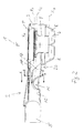
- ein Ausführungsbeispiel der Ablaufarmatur gemäß der vorliegenden Erfindung in einer isometrischen Querschnittsansicht,
- Fig. 2
- einen Schnitt in Strömungsrichtung durch die Ablaufarmatur gemäß
Fig. 1 , - Fig. 3
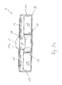
- einen Schnitt quer zur Strömungsrichtung durch die Ablaufarmatur gemäß
Fig. 1 im Bereich der Sperrwasserbarriere und - Fig. 4
- schematisch die verschiedenen Volumina und Volumenverhältnisse im Reservoirvolumen der Ablaufarmatur gemäß
Fig. 1 .
- Fig. 1
- An embodiment of the drain fitting according to the present invention in an isometric cross-sectional view,
- Fig. 2
- a section in the flow direction through the drain fitting according to
Fig. 1 . - Fig. 3
- a section transverse to the flow direction through the drain fitting according to
Fig. 1 in the area of the barrier barrier and - Fig. 4
- schematically the different volumes and volume ratios in the reservoir volume of the drain fitting according to
Fig. 1 ,
Der Stutzen 2 weist einen Stutzenanschlussabschnitt 2a auf, der das Innere des Stutzens 2 mit der übrigen Gehäusekammer 6 verbindet und einen Teil des Reservoirvolumens VR bildet,
wobei der Geruchverschluss mittels in dem Tauchrohr 9 und in dem Reservoirvolumen VR vorgehaltenem Sperrwasser bewirkt wird. Das Sperrwasser kann ein maximales Sperrwasserniveau X1 (vor einem Störfall) und ein darunter befindliches minimales Sperrwasserniveau X2 (nach einem Störfall) einnehmen, wie dies anhand von gestrichelten Linien in
wherein the odor trap is effected by means of barrier water stored in the
Der Boden 12 des Stutzens 2 weist eine sich von einer ersten Seitenwand 13 zu einer gegenüberliegenden zweiten Seitenwand 14 des Stutzens 2 erstreckende Erhebung 15 mit einem Höhenversatz 14a auf, die den Strömungskanal 11 vorübergehend verengt und im Stutzenanschlussabschnitt 2a das Reservoirvolumen VR zum Auslauf 5 hin begrenzt. Die Erhebung 15 ist ein Konstruktionselement 10, welches eine Änderung der Strömungseigenschaften bzw. des Strömungsverhaltens in dem vom Innern des Tauchrohrs 9 zum Stutzenanschlussabschnitt 2a führenden Strömungskanal 11 bewirkt.The bottom 12 of the
Wie
In den
Um geeignete Stautaschen zu bilden, sind beide Schottwände 16 sowohl mit dem Boden im Stutzenanschlussabschnitt 2a als auch mit dem vorderen Teil der Erhebung 15 verbunden. Dabei entspricht die Höhe der Schottwände 16 (gemeint ist der Abstand zwischen der Schottwandoberkante und dem Stutzenboden) der Höhe der Erhebung 15 im höchsten Punkt, also der maximalen Höhe der Erhebung 15.In order to form suitable stowage pockets, both
Auch die Erhebung 15 hat eine besondere Form. So steigt die Oberfläche der Erhebung 15 in Strömungsrichtung zunächst allmählich an und sinkt dann nach dem höchsten Punkt wieder allmählich ab. Dabei hat die Erhebung 15 im vorliegenden Fall einen konvexen, und zwar einen parabelförmigen, Verlauf.The
Auch der Strömungskanal 11 ist zwischen dem Tauchrohr 9, insbesondere der Unterkante des Tauchrohrs 9, und dem vorderen Ende des Stutzenanschlussabschnitts 2a auf besondere Weise ausgebildet. So ist der vertikale Abstand zwischen der Unterkante des Tauchrohrs 9 und dem Gehäusegrund 7 um mehr als 25% kleiner als der horizontale Abstand zwischen der Unterkante des Tauchrohrs 9 und der am nächsten liegenden Gehäuseseitenwand 8, die hier, wie auch die gegenüberliegende Gehäuseseitenwand 8, einen schrägen Verlauf hat. So verlaufen die Gehäuseseitenwände 8, wie der Schnitt in den
Ferner zeigt
Claims (15)
Priority Applications (1)
| Application Number | Priority Date | Filing Date | Title |
|---|---|---|---|
| PL09168394T PL2157249T3 (en) | 2008-08-22 | 2009-08-21 | Drainage fitting with odour trap |
Applications Claiming Priority (1)
| Application Number | Priority Date | Filing Date | Title |
|---|---|---|---|
| DE202008011197U DE202008011197U1 (en) | 2008-08-22 | 2008-08-22 | Drain fitting with odor trap |
Publications (3)
| Publication Number | Publication Date |
|---|---|
| EP2157249A2 true EP2157249A2 (en) | 2010-02-24 |
| EP2157249A3 EP2157249A3 (en) | 2011-05-11 |
| EP2157249B1 EP2157249B1 (en) | 2014-06-18 |
Family
ID=41268210
Family Applications (2)
| Application Number | Title | Priority Date | Filing Date |
|---|---|---|---|
| EP09165624.9A Active EP2157248B1 (en) | 2008-08-22 | 2009-07-16 | Drainage fittings with smell lock |
| EP09168394.6A Active EP2157249B1 (en) | 2008-08-22 | 2009-08-21 | Drainage fitting with odour trap |
Family Applications Before (1)
| Application Number | Title | Priority Date | Filing Date |
|---|---|---|---|
| EP09165624.9A Active EP2157248B1 (en) | 2008-08-22 | 2009-07-16 | Drainage fittings with smell lock |
Country Status (6)
| Country | Link |
|---|---|
| EP (2) | EP2157248B1 (en) |
| DE (1) | DE202008011197U1 (en) |
| DK (2) | DK2157248T3 (en) |
| ES (2) | ES2527777T3 (en) |
| PL (2) | PL2157248T3 (en) |
| PT (2) | PT2157248E (en) |
Families Citing this family (6)
| Publication number | Priority date | Publication date | Assignee | Title |
|---|---|---|---|---|
| EP2426283A3 (en) * | 2010-09-01 | 2014-07-23 | Urs Gassmann | Multipurpose siphon |
| DE102010044940B4 (en) * | 2010-09-10 | 2022-01-27 | Stephan Wedi | Sewage drain with odor trap |
| DE102010046179A1 (en) * | 2010-09-23 | 2012-03-29 | Stephan Wedi | Wastewater drain with odor trap, especially as a drain for shower trays |
| CN103104025B (en) * | 2013-02-06 | 2015-12-09 | 开平市新明光五金制品有限公司 | A kind of floor drain with refuse container |
| KR20220142056A (en) * | 2021-04-14 | 2022-10-21 | 양정석 | Drain trap with a structure to block the transmission of between floors pathogens |
| CN113216364B (en) * | 2021-05-25 | 2022-09-20 | 广东电白建设集团有限公司 | Municipal deep well drainage device based on siphon effect |
Citations (7)
| Publication number | Priority date | Publication date | Assignee | Title |
|---|---|---|---|---|
| DE1864695U (en) | 1961-12-28 | 1962-12-27 | Gerard Beerts | SIPHON FOR WASHBASIN, TUBE, BATHTUBS, OR. DGL. |
| US3651826A (en) | 1969-11-19 | 1972-03-28 | Noriatsu Kojima | Drain trap for horizontal drain pipe |
| EP0634530A1 (en) | 1993-07-13 | 1995-01-18 | Firma Franz Viegener II | Odour seal for drainage device |
| EP1098041A1 (en) | 1999-11-03 | 2001-05-09 | Force 5 S.A. | Shower tray comprising a base which can be emptied by its lowest point |
| DE202005017965U1 (en) | 2005-11-15 | 2007-03-29 | Viega Gmbh & Co. Kg | Drainage device for a floor-level shower |
| DE102006058259A1 (en) | 2006-12-08 | 2008-06-19 | Kludi Gmbh & Co. Kg | Flat siphon for washstand or sink, comprises pipe body closed at its one end or bypasses into deflecting elbow and upper partition is arranged within tubing cross section of pipe body and lower partition is spaced axial to upper partition |
| DE202008001013U1 (en) | 2008-01-23 | 2009-06-18 | Viega Gmbh & Co. Kg | Drain fitting, especially for shower or bathtubs |
Family Cites Families (5)
| Publication number | Priority date | Publication date | Assignee | Title |
|---|---|---|---|---|
| DE9102860U1 (en) * | 1991-03-09 | 1991-05-29 | Fa. Franz Viegener Ii, 5952 Attendorn, De | |
| DE19649239A1 (en) * | 1996-06-27 | 1998-01-02 | Scheffer Ohg Franz | Drain fitting with adjustable immersion pipe and welded housing |
| ATE432392T1 (en) * | 2005-12-13 | 2009-06-15 | Geberit Technik Ag | DRAIN FOR SANITARY APPARATUS |
| DE102006053756A1 (en) * | 2006-11-13 | 2008-05-15 | Hansgrohe Ag | Drainage armature for shower tub or bath tub, has separating wall arranged between interior and discharge nozzle, and limiting wall of interior connected with upper wall of housing in gas-tight manner and designed as single unit |
| DE102006053751A1 (en) | 2006-11-13 | 2008-05-15 | Hansgrohe Ag | Drainage fitting for e.g. shower tub, has opening formed in partition, and stopper closing opening and comprising starting device that is accessible from interior space of housing, where partition is between space and discharge nozzle |
-
2008
- 2008-08-22 DE DE202008011197U patent/DE202008011197U1/en not_active Expired - Lifetime
-
2009
- 2009-07-16 PT PT91656249T patent/PT2157248E/en unknown
- 2009-07-16 EP EP09165624.9A patent/EP2157248B1/en active Active
- 2009-07-16 ES ES09165624.9T patent/ES2527777T3/en active Active
- 2009-07-16 PL PL09165624T patent/PL2157248T3/en unknown
- 2009-07-16 DK DK09165624.9T patent/DK2157248T3/en active
- 2009-08-21 PT PT91683946T patent/PT2157249E/en unknown
- 2009-08-21 ES ES09168394.6T patent/ES2496667T3/en active Active
- 2009-08-21 DK DK09168394.6T patent/DK2157249T3/en active
- 2009-08-21 EP EP09168394.6A patent/EP2157249B1/en active Active
- 2009-08-21 PL PL09168394T patent/PL2157249T3/en unknown
Patent Citations (7)
| Publication number | Priority date | Publication date | Assignee | Title |
|---|---|---|---|---|
| DE1864695U (en) | 1961-12-28 | 1962-12-27 | Gerard Beerts | SIPHON FOR WASHBASIN, TUBE, BATHTUBS, OR. DGL. |
| US3651826A (en) | 1969-11-19 | 1972-03-28 | Noriatsu Kojima | Drain trap for horizontal drain pipe |
| EP0634530A1 (en) | 1993-07-13 | 1995-01-18 | Firma Franz Viegener II | Odour seal for drainage device |
| EP1098041A1 (en) | 1999-11-03 | 2001-05-09 | Force 5 S.A. | Shower tray comprising a base which can be emptied by its lowest point |
| DE202005017965U1 (en) | 2005-11-15 | 2007-03-29 | Viega Gmbh & Co. Kg | Drainage device for a floor-level shower |
| DE102006058259A1 (en) | 2006-12-08 | 2008-06-19 | Kludi Gmbh & Co. Kg | Flat siphon for washstand or sink, comprises pipe body closed at its one end or bypasses into deflecting elbow and upper partition is arranged within tubing cross section of pipe body and lower partition is spaced axial to upper partition |
| DE202008001013U1 (en) | 2008-01-23 | 2009-06-18 | Viega Gmbh & Co. Kg | Drain fitting, especially for shower or bathtubs |
Also Published As
| Publication number | Publication date |
|---|---|
| EP2157248A3 (en) | 2011-05-11 |
| PT2157249E (en) | 2014-09-08 |
| PT2157248E (en) | 2015-02-04 |
| EP2157249A3 (en) | 2011-05-11 |
| DK2157248T3 (en) | 2015-01-26 |
| PL2157248T3 (en) | 2015-04-30 |
| DK2157249T3 (en) | 2014-09-15 |
| EP2157248B1 (en) | 2014-11-19 |
| DE202008011197U1 (en) | 2009-12-31 |
| PL2157249T3 (en) | 2014-11-28 |
| ES2527777T3 (en) | 2015-01-29 |
| ES2496667T3 (en) | 2014-09-19 |
| EP2157248A2 (en) | 2010-02-24 |
| EP2157249B1 (en) | 2014-06-18 |
Similar Documents
| Publication | Publication Date | Title |
|---|---|---|
| EP2157249B1 (en) | Drainage fitting with odour trap | |
| EP2508686B1 (en) | Retention assembly for precipitation and waste water | |
| WO2015185460A1 (en) | Deflecting bend | |
| DE202014007392U1 (en) | Water outlet with multiple siphon trap | |
| DE102005012439A1 (en) | Water drain, especially for a building roof, has an inflow opening with an outflow pipe for surface water and a second inflow with a smaller outflow pipe to take a pressure flow of higher accumulated water | |
| EP2157247B1 (en) | Drain outlet | |
| EP1882786B1 (en) | Pipe elbow for a sanitary conduit | |
| EP2369088A1 (en) | Device for removing water from roofs | |
| EP2765249B1 (en) | Outlet fitting for a toilet cistern | |
| EP3106574A1 (en) | Pipe branch section for downpipes | |
| EP3199715B1 (en) | Overflow for a basin, in particular rinsing basin | |
| EP3469158B1 (en) | Discharge valve | |
| EP2995731B1 (en) | Water outlet with multiple siphon odour trap | |
| DE4212205C2 (en) | Swimming pool drain system | |
| DE102018111300A1 (en) | Packing unit, packing system and shaft element | |
| EP0518912B1 (en) | Clearing or sedimentation tank | |
| EP3183048B1 (en) | Rain water filter | |
| DE102007056294B3 (en) | Submersible wall system for floating matter retention in overflow systems | |
| DE102005012438B4 (en) | water draining | |
| DE2822299A1 (en) | Flow regulator for fluid - has flexible walled chamber filled with low density fluid and acting as throttle valve | |
| EP3896234A1 (en) | Fitting assembly | |
| DE102005019190A1 (en) | Drain body and method for removing a liquid | |
| CH716375B1 (en) | Fitting arrangement, in particular for flush mounting. | |
| EP2921596B1 (en) | Drain valve | |
| WO2019002332A1 (en) | Odour trap element for installation in an outflow, in particular in the outflow of a waterless urinal |
Legal Events
| Date | Code | Title | Description |
|---|---|---|---|
| PUAI | Public reference made under article 153(3) epc to a published international application that has entered the european phase |
Free format text: ORIGINAL CODE: 0009012 |
|
| AK | Designated contracting states |
Kind code of ref document: A2 Designated state(s): AT BE BG CH CY CZ DE DK EE ES FI FR GB GR HR HU IE IS IT LI LT LU LV MC MK MT NL NO PL PT RO SE SI SK SM TR |
|
| AX | Request for extension of the european patent |
Extension state: AL BA RS |
|
| REG | Reference to a national code |
Ref country code: DE Ref legal event code: R079 Ref document number: 502009009524 Country of ref document: DE Free format text: PREVIOUS MAIN CLASS: E03C0001290000 Ipc: E03F0005040000 |
|
| PUAL | Search report despatched |
Free format text: ORIGINAL CODE: 0009013 |
|
| AK | Designated contracting states |
Kind code of ref document: A3 Designated state(s): AT BE BG CH CY CZ DE DK EE ES FI FR GB GR HR HU IE IS IT LI LT LU LV MC MK MT NL NO PL PT RO SE SI SK SM TR |
|
| AX | Request for extension of the european patent |
Extension state: AL BA RS |
|
| RIC1 | Information provided on ipc code assigned before grant |
Ipc: E03F 5/04 20060101AFI20110401BHEP |
|
| 17P | Request for examination filed |
Effective date: 20110620 |
|
| 17Q | First examination report despatched |
Effective date: 20130417 |
|
| GRAP | Despatch of communication of intention to grant a patent |
Free format text: ORIGINAL CODE: EPIDOSNIGR1 |
|
| INTG | Intention to grant announced |
Effective date: 20140311 |
|
| GRAS | Grant fee paid |
Free format text: ORIGINAL CODE: EPIDOSNIGR3 |
|
| GRAA | (expected) grant |
Free format text: ORIGINAL CODE: 0009210 |
|
| AK | Designated contracting states |
Kind code of ref document: B1 Designated state(s): AT BE BG CH CY CZ DE DK EE ES FI FR GB GR HR HU IE IS IT LI LT LU LV MC MK MT NL NO PL PT RO SE SI SK SM TR |
|
| REG | Reference to a national code |
Ref country code: GB Ref legal event code: FG4D Free format text: NOT ENGLISH |
|
| REG | Reference to a national code |
Ref country code: CH Ref legal event code: NV Representative=s name: TROESCH SCHEIDEGGER WERNER AG, CH Ref country code: CH Ref legal event code: EP |
|
| REG | Reference to a national code |
Ref country code: AT Ref legal event code: REF Ref document number: 673458 Country of ref document: AT Kind code of ref document: T Effective date: 20140715 |
|
| REG | Reference to a national code |
Ref country code: IE Ref legal event code: FG4D Free format text: LANGUAGE OF EP DOCUMENT: GERMAN |
|
| REG | Reference to a national code |
Ref country code: DE Ref legal event code: R096 Ref document number: 502009009524 Country of ref document: DE Effective date: 20140731 |
|
| REG | Reference to a national code |
Ref country code: NL Ref legal event code: T3 |
|
| REG | Reference to a national code |
Ref country code: PT Ref legal event code: SC4A Free format text: AVAILABILITY OF NATIONAL TRANSLATION Effective date: 20140827 |
|
| REG | Reference to a national code |
Ref country code: DK Ref legal event code: T3 Effective date: 20140909 |
|
| REG | Reference to a national code |
Ref country code: ES Ref legal event code: FG2A Ref document number: 2496667 Country of ref document: ES Kind code of ref document: T3 Effective date: 20140919 |
|
| PG25 | Lapsed in a contracting state [announced via postgrant information from national office to epo] |
Ref country code: FI Free format text: LAPSE BECAUSE OF FAILURE TO SUBMIT A TRANSLATION OF THE DESCRIPTION OR TO PAY THE FEE WITHIN THE PRESCRIBED TIME-LIMIT Effective date: 20140618 Ref country code: LT Free format text: LAPSE BECAUSE OF FAILURE TO SUBMIT A TRANSLATION OF THE DESCRIPTION OR TO PAY THE FEE WITHIN THE PRESCRIBED TIME-LIMIT Effective date: 20140618 Ref country code: GR Free format text: LAPSE BECAUSE OF FAILURE TO SUBMIT A TRANSLATION OF THE DESCRIPTION OR TO PAY THE FEE WITHIN THE PRESCRIBED TIME-LIMIT Effective date: 20140919 Ref country code: CY Free format text: LAPSE BECAUSE OF FAILURE TO SUBMIT A TRANSLATION OF THE DESCRIPTION OR TO PAY THE FEE WITHIN THE PRESCRIBED TIME-LIMIT Effective date: 20140618 Ref country code: NO Free format text: LAPSE BECAUSE OF FAILURE TO SUBMIT A TRANSLATION OF THE DESCRIPTION OR TO PAY THE FEE WITHIN THE PRESCRIBED TIME-LIMIT Effective date: 20140918 |
|
| REG | Reference to a national code |
Ref country code: LT Ref legal event code: MG4D |
|
| PG25 | Lapsed in a contracting state [announced via postgrant information from national office to epo] |
Ref country code: SE Free format text: LAPSE BECAUSE OF FAILURE TO SUBMIT A TRANSLATION OF THE DESCRIPTION OR TO PAY THE FEE WITHIN THE PRESCRIBED TIME-LIMIT Effective date: 20140618 Ref country code: HR Free format text: LAPSE BECAUSE OF FAILURE TO SUBMIT A TRANSLATION OF THE DESCRIPTION OR TO PAY THE FEE WITHIN THE PRESCRIBED TIME-LIMIT Effective date: 20140618 Ref country code: LV Free format text: LAPSE BECAUSE OF FAILURE TO SUBMIT A TRANSLATION OF THE DESCRIPTION OR TO PAY THE FEE WITHIN THE PRESCRIBED TIME-LIMIT Effective date: 20140618 |
|
| REG | Reference to a national code |
Ref country code: PL Ref legal event code: T3 |
|
| PG25 | Lapsed in a contracting state [announced via postgrant information from national office to epo] |
Ref country code: RO Free format text: LAPSE BECAUSE OF FAILURE TO SUBMIT A TRANSLATION OF THE DESCRIPTION OR TO PAY THE FEE WITHIN THE PRESCRIBED TIME-LIMIT Effective date: 20140618 Ref country code: EE Free format text: LAPSE BECAUSE OF FAILURE TO SUBMIT A TRANSLATION OF THE DESCRIPTION OR TO PAY THE FEE WITHIN THE PRESCRIBED TIME-LIMIT Effective date: 20140618 |
|
| REG | Reference to a national code |
Ref country code: SK Ref legal event code: T3 Ref document number: E 17340 Country of ref document: SK |
|
| PG25 | Lapsed in a contracting state [announced via postgrant information from national office to epo] |
Ref country code: IS Free format text: LAPSE BECAUSE OF FAILURE TO SUBMIT A TRANSLATION OF THE DESCRIPTION OR TO PAY THE FEE WITHIN THE PRESCRIBED TIME-LIMIT Effective date: 20141018 |
|
| REG | Reference to a national code |
Ref country code: DE Ref legal event code: R097 Ref document number: 502009009524 Country of ref document: DE |
|
| PG25 | Lapsed in a contracting state [announced via postgrant information from national office to epo] |
Ref country code: LU Free format text: LAPSE BECAUSE OF FAILURE TO SUBMIT A TRANSLATION OF THE DESCRIPTION OR TO PAY THE FEE WITHIN THE PRESCRIBED TIME-LIMIT Effective date: 20140821 Ref country code: MC Free format text: LAPSE BECAUSE OF FAILURE TO SUBMIT A TRANSLATION OF THE DESCRIPTION OR TO PAY THE FEE WITHIN THE PRESCRIBED TIME-LIMIT Effective date: 20140618 |
|
| PLBE | No opposition filed within time limit |
Free format text: ORIGINAL CODE: 0009261 |
|
| STAA | Information on the status of an ep patent application or granted ep patent |
Free format text: STATUS: NO OPPOSITION FILED WITHIN TIME LIMIT |
|
| REG | Reference to a national code |
Ref country code: IE Ref legal event code: MM4A |
|
| 26N | No opposition filed |
Effective date: 20150319 |
|
| PG25 | Lapsed in a contracting state [announced via postgrant information from national office to epo] |
Ref country code: SI Free format text: LAPSE BECAUSE OF FAILURE TO SUBMIT A TRANSLATION OF THE DESCRIPTION OR TO PAY THE FEE WITHIN THE PRESCRIBED TIME-LIMIT Effective date: 20140618 |
|
| PG25 | Lapsed in a contracting state [announced via postgrant information from national office to epo] |
Ref country code: IE Free format text: LAPSE BECAUSE OF NON-PAYMENT OF DUE FEES Effective date: 20140821 |
|
| PG25 | Lapsed in a contracting state [announced via postgrant information from national office to epo] |
Ref country code: SM Free format text: LAPSE BECAUSE OF FAILURE TO SUBMIT A TRANSLATION OF THE DESCRIPTION OR TO PAY THE FEE WITHIN THE PRESCRIBED TIME-LIMIT Effective date: 20140618 |
|
| PG25 | Lapsed in a contracting state [announced via postgrant information from national office to epo] |
Ref country code: MT Free format text: LAPSE BECAUSE OF FAILURE TO SUBMIT A TRANSLATION OF THE DESCRIPTION OR TO PAY THE FEE WITHIN THE PRESCRIBED TIME-LIMIT Effective date: 20140618 Ref country code: BG Free format text: LAPSE BECAUSE OF FAILURE TO SUBMIT A TRANSLATION OF THE DESCRIPTION OR TO PAY THE FEE WITHIN THE PRESCRIBED TIME-LIMIT Effective date: 20140618 |
|
| PG25 | Lapsed in a contracting state [announced via postgrant information from national office to epo] |
Ref country code: HU Free format text: LAPSE BECAUSE OF FAILURE TO SUBMIT A TRANSLATION OF THE DESCRIPTION OR TO PAY THE FEE WITHIN THE PRESCRIBED TIME-LIMIT; INVALID AB INITIO Effective date: 20090821 Ref country code: TR Free format text: LAPSE BECAUSE OF FAILURE TO SUBMIT A TRANSLATION OF THE DESCRIPTION OR TO PAY THE FEE WITHIN THE PRESCRIBED TIME-LIMIT Effective date: 20140618 |
|
| REG | Reference to a national code |
Ref country code: FR Ref legal event code: PLFP Year of fee payment: 8 |
|
| REG | Reference to a national code |
Ref country code: DE Ref legal event code: R082 Ref document number: 502009009524 Country of ref document: DE Representative=s name: COHAUSZ & FLORACK PATENT- UND RECHTSANWAELTE P, DE Ref country code: DE Ref legal event code: R081 Ref document number: 502009009524 Country of ref document: DE Owner name: VIEGA TECHNOLOGY GMBH & CO. KG, DE Free format text: FORMER OWNER: VIEGA GMBH & CO. KG, 57439 ATTENDORN, DE |
|
| REG | Reference to a national code |
Ref country code: NL Ref legal event code: PD Owner name: VIEGA TECHNOLOGY GMBH & CO. KG; DE Free format text: DETAILS ASSIGNMENT: CHANGE OF OWNER(S), ASSIGNMENT; FORMER OWNER NAME: VIEGA GMBH & CO. KG Effective date: 20170412 |
|
| REG | Reference to a national code |
Ref country code: SK Ref legal event code: PC4A Ref document number: E 17340 Country of ref document: SK Owner name: VIEGA TECHNOLOGY GMBH & CO. KG, ATTENDORN, DE Free format text: FORMER OWNER: VIEGA GMBH & CO. KG, ATTENDORN, DE Effective date: 20161230 Ref country code: GB Ref legal event code: 732E Free format text: REGISTERED BETWEEN 20170706 AND 20170715 |
|
| REG | Reference to a national code |
Ref country code: FR Ref legal event code: PLFP Year of fee payment: 9 |
|
| REG | Reference to a national code |
Ref country code: ES Ref legal event code: PC2A Owner name: VIEGA TECHNOLOGY GMBH & CO. KG Effective date: 20170925 |
|
| REG | Reference to a national code |
Ref country code: FR Ref legal event code: TP Owner name: VIEGA TECHNOLOGY GMBH & CO. KG, DE Effective date: 20171013 |
|
| REG | Reference to a national code |
Ref country code: CH Ref legal event code: PUE Owner name: VIEGA TECHNOLOGY GMBH AND CO. KG, DE Free format text: FORMER OWNER: VIEGA GMBH AND CO. KG, DE |
|
| PG25 | Lapsed in a contracting state [announced via postgrant information from national office to epo] |
Ref country code: MK Free format text: LAPSE BECAUSE OF FAILURE TO SUBMIT A TRANSLATION OF THE DESCRIPTION OR TO PAY THE FEE WITHIN THE PRESCRIBED TIME-LIMIT Effective date: 20140618 |
|
| REG | Reference to a national code |
Ref country code: FR Ref legal event code: PLFP Year of fee payment: 10 |
|
| PGFP | Annual fee paid to national office [announced via postgrant information from national office to epo] |
Ref country code: NL Payment date: 20210824 Year of fee payment: 13 |
|
| PGFP | Annual fee paid to national office [announced via postgrant information from national office to epo] |
Ref country code: CZ Payment date: 20210715 Year of fee payment: 13 Ref country code: AT Payment date: 20210824 Year of fee payment: 13 |
|
| PGFP | Annual fee paid to national office [announced via postgrant information from national office to epo] |
Ref country code: BE Payment date: 20210823 Year of fee payment: 13 Ref country code: PL Payment date: 20210714 Year of fee payment: 13 Ref country code: SK Payment date: 20210714 Year of fee payment: 13 Ref country code: DK Payment date: 20210826 Year of fee payment: 13 |
|
| PGFP | Annual fee paid to national office [announced via postgrant information from national office to epo] |
Ref country code: PT Payment date: 20210720 Year of fee payment: 13 |
|
| PGFP | Annual fee paid to national office [announced via postgrant information from national office to epo] |
Ref country code: GB Payment date: 20220822 Year of fee payment: 14 Ref country code: ES Payment date: 20220922 Year of fee payment: 14 |
|
| PGFP | Annual fee paid to national office [announced via postgrant information from national office to epo] |
Ref country code: FR Payment date: 20220822 Year of fee payment: 14 |
|
| REG | Reference to a national code |
Ref country code: DK Ref legal event code: EBP Effective date: 20220831 |
|
| REG | Reference to a national code |
Ref country code: NL Ref legal event code: MM Effective date: 20220901 |
|
| REG | Reference to a national code |
Ref country code: SK Ref legal event code: MM4A Ref document number: E 17340 Country of ref document: SK Effective date: 20220821 |
|
| REG | Reference to a national code |
Ref country code: AT Ref legal event code: MM01 Ref document number: 673458 Country of ref document: AT Kind code of ref document: T Effective date: 20220821 |
|
| PG25 | Lapsed in a contracting state [announced via postgrant information from national office to epo] |
Ref country code: PT Free format text: LAPSE BECAUSE OF NON-PAYMENT OF DUE FEES Effective date: 20230221 Ref country code: CZ Free format text: LAPSE BECAUSE OF NON-PAYMENT OF DUE FEES Effective date: 20220821 Ref country code: AT Free format text: LAPSE BECAUSE OF NON-PAYMENT OF DUE FEES Effective date: 20220821 |
|
| REG | Reference to a national code |
Ref country code: BE Ref legal event code: MM Effective date: 20220831 |
|
| PG25 | Lapsed in a contracting state [announced via postgrant information from national office to epo] |
Ref country code: SK Free format text: LAPSE BECAUSE OF NON-PAYMENT OF DUE FEES Effective date: 20220821 |
|
| PG25 | Lapsed in a contracting state [announced via postgrant information from national office to epo] |
Ref country code: NL Free format text: LAPSE BECAUSE OF NON-PAYMENT OF DUE FEES Effective date: 20220901 |
|
| PG25 | Lapsed in a contracting state [announced via postgrant information from national office to epo] |
Ref country code: DK Free format text: LAPSE BECAUSE OF NON-PAYMENT OF DUE FEES Effective date: 20220831 |
|
| PG25 | Lapsed in a contracting state [announced via postgrant information from national office to epo] |
Ref country code: BE Free format text: LAPSE BECAUSE OF NON-PAYMENT OF DUE FEES Effective date: 20220831 |
|
| PGFP | Annual fee paid to national office [announced via postgrant information from national office to epo] |
Ref country code: IT Payment date: 20230823 Year of fee payment: 15 Ref country code: CH Payment date: 20230902 Year of fee payment: 15 |
|
| PG25 | Lapsed in a contracting state [announced via postgrant information from national office to epo] |
Ref country code: PL Free format text: LAPSE BECAUSE OF NON-PAYMENT OF DUE FEES Effective date: 20220821 |
|
| PGFP | Annual fee paid to national office [announced via postgrant information from national office to epo] |
Ref country code: DE Payment date: 20230823 Year of fee payment: 15 |
|
| GBPC | Gb: european patent ceased through non-payment of renewal fee |
Effective date: 20230821 |