EP2156925A2 - Sander - Google Patents
Sander Download PDFInfo
- Publication number
- EP2156925A2 EP2156925A2 EP20090168250 EP09168250A EP2156925A2 EP 2156925 A2 EP2156925 A2 EP 2156925A2 EP 20090168250 EP20090168250 EP 20090168250 EP 09168250 A EP09168250 A EP 09168250A EP 2156925 A2 EP2156925 A2 EP 2156925A2
- Authority
- EP
- European Patent Office
- Prior art keywords
- platen
- sander
- power tool
- tool according
- tool body
- Prior art date
- Legal status (The legal status is an assumption and is not a legal conclusion. Google has not performed a legal analysis and makes no representation as to the accuracy of the status listed.)
- Granted
Links
- 230000000717 retained effect Effects 0.000 claims description 2
- 230000001419 dependent effect Effects 0.000 claims 2
- 239000000428 dust Substances 0.000 description 18
- 238000000605 extraction Methods 0.000 description 11
- 238000000034 method Methods 0.000 description 9
- 230000008878 coupling Effects 0.000 description 8
- 238000010168 coupling process Methods 0.000 description 8
- 238000005859 coupling reaction Methods 0.000 description 8
- 238000010276 construction Methods 0.000 description 4
- 239000003082 abrasive agent Substances 0.000 description 2
- 238000001816 cooling Methods 0.000 description 2
- 230000002093 peripheral effect Effects 0.000 description 2
- 241000283973 Oryctolagus cuniculus Species 0.000 description 1
- 244000137852 Petrea volubilis Species 0.000 description 1
- 241000270666 Testudines Species 0.000 description 1
- 239000003086 colorant Substances 0.000 description 1
- 238000004891 communication Methods 0.000 description 1
- 230000009977 dual effect Effects 0.000 description 1
- 239000004744 fabric Substances 0.000 description 1
- 239000000463 material Substances 0.000 description 1
- 230000013011 mating Effects 0.000 description 1
- 239000007769 metal material Substances 0.000 description 1
- 238000012986 modification Methods 0.000 description 1
- 230000004048 modification Effects 0.000 description 1
- NJPPVKZQTLUDBO-UHFFFAOYSA-N novaluron Chemical compound C1=C(Cl)C(OC(F)(F)C(OC(F)(F)F)F)=CC=C1NC(=O)NC(=O)C1=C(F)C=CC=C1F NJPPVKZQTLUDBO-UHFFFAOYSA-N 0.000 description 1
Images


Classifications
-
- B—PERFORMING OPERATIONS; TRANSPORTING
- B24—GRINDING; POLISHING
- B24B—MACHINES, DEVICES, OR PROCESSES FOR GRINDING OR POLISHING; DRESSING OR CONDITIONING OF ABRADING SURFACES; FEEDING OF GRINDING, POLISHING, OR LAPPING AGENTS
- B24B41/00—Component parts such as frames, beds, carriages, headstocks
- B24B41/04—Headstocks; Working-spindles; Features relating thereto
-
- B—PERFORMING OPERATIONS; TRANSPORTING
- B24—GRINDING; POLISHING
- B24B—MACHINES, DEVICES, OR PROCESSES FOR GRINDING OR POLISHING; DRESSING OR CONDITIONING OF ABRADING SURFACES; FEEDING OF GRINDING, POLISHING, OR LAPPING AGENTS
- B24B23/00—Portable grinding machines, e.g. hand-guided; Accessories therefor
- B24B23/02—Portable grinding machines, e.g. hand-guided; Accessories therefor with rotating grinding tools; Accessories therefor
- B24B23/03—Portable grinding machines, e.g. hand-guided; Accessories therefor with rotating grinding tools; Accessories therefor the tool being driven in a combined movement
-
- B—PERFORMING OPERATIONS; TRANSPORTING
- B24—GRINDING; POLISHING
- B24B—MACHINES, DEVICES, OR PROCESSES FOR GRINDING OR POLISHING; DRESSING OR CONDITIONING OF ABRADING SURFACES; FEEDING OF GRINDING, POLISHING, OR LAPPING AGENTS
- B24B23/00—Portable grinding machines, e.g. hand-guided; Accessories therefor
- B24B23/04—Portable grinding machines, e.g. hand-guided; Accessories therefor with oscillating grinding tools; Accessories therefor
-
- B—PERFORMING OPERATIONS; TRANSPORTING
- B24—GRINDING; POLISHING
- B24B—MACHINES, DEVICES, OR PROCESSES FOR GRINDING OR POLISHING; DRESSING OR CONDITIONING OF ABRADING SURFACES; FEEDING OF GRINDING, POLISHING, OR LAPPING AGENTS
- B24B45/00—Means for securing grinding wheels on rotary arbors
- B24B45/006—Quick mount and release means for disc-like wheels, e.g. on power tools
-
- B—PERFORMING OPERATIONS; TRANSPORTING
- B24—GRINDING; POLISHING
- B24B—MACHINES, DEVICES, OR PROCESSES FOR GRINDING OR POLISHING; DRESSING OR CONDITIONING OF ABRADING SURFACES; FEEDING OF GRINDING, POLISHING, OR LAPPING AGENTS
- B24B49/00—Measuring or gauging equipment for controlling the feed movement of the grinding tool or work; Arrangements of indicating or measuring equipment, e.g. for indicating the start of the grinding operation
-
- Y—GENERAL TAGGING OF NEW TECHNOLOGICAL DEVELOPMENTS; GENERAL TAGGING OF CROSS-SECTIONAL TECHNOLOGIES SPANNING OVER SEVERAL SECTIONS OF THE IPC; TECHNICAL SUBJECTS COVERED BY FORMER USPC CROSS-REFERENCE ART COLLECTIONS [XRACs] AND DIGESTS
- Y10—TECHNICAL SUBJECTS COVERED BY FORMER USPC
- Y10T—TECHNICAL SUBJECTS COVERED BY FORMER US CLASSIFICATION
- Y10T29/00—Metal working
- Y10T29/49—Method of mechanical manufacture
- Y10T29/49826—Assembling or joining
- Y10T29/49863—Assembling or joining with prestressing of part
- Y10T29/4987—Elastic joining of parts
Definitions
- the present invention relates to a sander or other power tool for moving an abrasive medium, having a plurality of platens that can be selectively attached to a common base, preferably without the use of a hand tool.
- Sanders typically have a platen to which an abrasive medium, such as sandpaper, is attached.
- abrasive medium such as sandpaper
- Sanders with removable, differently shaped platens are available to permit the user of the sander to change the platen to one with a shape that is best suited for a given sander task.
- Such removable platens typically are secured to the sander by way of one or more threaded fasteners (e.g., socket head cap screws). These threaded fasteners require the use of tools (e.g., Allen wrenches) to remove them from the sander to thereby decouple the platen from the sander.
- a power tool for moving an abrasive medium comprising a tool body and a drive system housed in the tool body, the drive system including an output member.
- a retaining member may be disposed on the tool body.
- a first platen having a first attachment hub may be selectively coupled with the retaining member in an installed position.
- the first platen may have a first rotatable member that selectively attaches to the output member in a first mode of operation.
- a second platen having a second attachment hub may selectively couple with the retaining member in an installed position.
- the second platen may have a second rotatable member that selectively attaches to the output member in a second mode of operation.
- a mode selector may be disposed on the tool body.
- the mode selector may have a movable member, and preferably has a visible key, for example a pictorial or other symbolic key (e.g. one or more letters and/or numbers and/or images).
- the movable member may be movable between at least a first position that corresponds to a first output member speed and a second position that corresponds to a second output member speed.
- the movable member may be substantially aligned with a first graphic (i.e. symbol or set of symbols) on the visible key that corresponds to the first platen in the first position and second graphic on the visible key that corresponds to the second platen in the second position.
- a second aspect of the invention provides a power tool for moving an abrasive medium, comprising: a tool body; a drive system housed in the tool body and including an output member; a retaining member disposed on the tool body; a first platen having a first attachment hub that selectively couples with the retaining member in an installed position, the first platen having a first rotatable member that selectively attaches to the output member in a first mode of operation; a second platen having a second attachment hub that selectively couples with the retaining member in an installed position, the second platen having a second rotatable member that selectively attaches to the output member in a second mode of operation; and a mode selector disposed on the tool body and having a movable member, wherein the movable member is movable between at least a first position in which the first platen is used in the first mode of operation at a first output member speed and a second position in which the second platen is used (instead of the first platen) in the second
- the movable member preferably is substantially aligned with a first graphic (i.e. symbol or set of symbols) that corresponds to the first platen when the movable member is in the first position, and preferably is substantially aligned with a second graphic that corresponds to the second platen when the movable member is in the second position.
- a first graphic i.e. symbol or set of symbols
- a second graphic that corresponds to the second platen when the movable member is in the second position.
- the first rotatable member of the first platen may be mounted for an orbit having a first offset relative to the output member.
- the second rotatable member of the second platen may be mounted for an orbit having a second offset relative to the output member.
- the first and second offsets may be distinct.
- the first rotatable member may include a first fan having a first counterbalance disposed thereon.
- the second rotatable member may comprise a second fan having a second counterbalance disposed thereon.
- the first and second counterbalances may have distinct masses.
- the first platen may be an orbital platen configured for orbital sanding in the installed position and the second platen may be a random orbit platen configured for random orbit sanding in the installed position.
- the first platen may, for example, comprise a plurality of flexible columns having first ends coupled to the first platen and second ends that are selectively retained by the tool body in the installed position.
- the retaining member may comprise a wireframe that selectively nests in respective grooves defined around each of the first and second attachment hubs respectively in the installed position.
- a button or other actuator may be disposed on the tool body. The actuator may cooperate with the wireframe and be movable to a release position to spread the wireframe and release the wireframe from the respective grooves to exchange between the first and second platens.
- a chamfered annular leading edge is defined on each of the first and second attachment hubs respectively. Movement of a respective first or second platen to the installed position may cause the annular leading edge to spread the wireframe until continued movement toward the installed position causes the wireframe to nest in the respective grooves.
- the tool may include a third platen having a third attachment hub that selectively couples with the retaining member in an installed position.
- the third platen may have a third rotatable member that selectively attaches to the output member in a third mode of operation.
- the first platen may define an iron-shaped profile having a substantially flat first end and a substantially pointed second end.
- the first platen may comprise a dust chute arranged proximate to the substantially pointed second end.
- the third platen may define an iron-shaped profile having a substantially pointed first end and a substantially flat second end.
- the third platen may comprise a dust chute arranged proximate to the substantially flat second end.
- the substantially flat first end of the first platen is aligned with a forward end of the tool in the installed position and the substantially pointed first end of a third platen is aligned with a forward end of the tool in the installed position.
- the tool may comprise a speed control switch that communicates with the mode selector.
- the mode selector may define a rib that cams across an input of the speed control switch upon movement of the mode selector to toggle between the first output member speed and the second output member speed.
- a third aspect of the invention provides a method of selecting an appropriate operating rotational speed and abrading platen (e.g. sanding platen) of a powered abrading tool (e.g. a sander), including providing the tool with a tool body, a drive system and first and second platens.
- the tool body may have a mode selector including a movable member and a visible key, for example a pictorial or other symbolic key (e.g. one or more letters and/or numbers and/or images).
- the drive system can have an output member.
- the method preferably further includes moving the movable member to one of a first position or a second position.
- the first position may correspond to a graphic (i.e.
- the method may further include, mounting one of the first or second platen to the tool body according to the selected first or second position.
- the method may include rotating a dial causing a rib defined on the dial to cam across an input of a speed control switch and change the speed of the output member between a first and second output member speed.
- mounting one of the first or second platens to the tool body may include urging an attachment hub associated with a respective first or second platen into engagement with a wireframe retaining member disposed on the tool body.
- the method further includes, urging the attachment hub into engagement with the wireframe retaining member, such that the wireframe retaining member rides over a chamfered annular leading edge defined on the attachment hub and spreads outwardly until the wireframe retaining member nests at least partially around the selected attachment hub in a groove defined on the selected attachment hub.
- an exemplary abrasive material removal tool is generally indicated by reference numeral 10.
- the abrasive material removal tool hereinafter sander 10
- the sander 10 can further include a drive system 18 that is housed in a cavity defined by the clam shell portions 14 and 16.
- the tool body 12 and the drive system 18 can be conventional in their construction and operation, and as such, need not be discussed in significant detail herein.
- the tool body 12 can further define a dust extraction port 20 ( Fig. 4 ) to which dust can be extracted to a dust chamber 21.
- the drive system 18 can selectively couple with a plurality of platens, collectively referred at reference numeral 22 as will be described in greater detail herein.
- a mode selector 24 can be arranged on a forward portion of the tool body 12.
- the mode selector 24 can include a movable member or dial 26 and a pictorial key 28.
- a base release button 30 can be provided proximate to the mode selector 24.
- a power cord 32 can extend from the tool body 12 to supply electrical current to the sander 10. It is appreciated that while the sander 10 is shown operatively associated with a power cord 32 for alternating current (AC) operation, the sander 10 can also be configured for operation with other power sources, such as direct current (DC) or a pneumatic input.
- AC alternating current
- DC direct current
- the drive system 18 can include an electric motor 36 ( Fig. 4 ) mounted within the tool body 12 and having an output member 38.
- the output member 38 can define a male spline 40.
- a fan (not shown) can be mounted on the output member 38 for rotation therewith.
- the fan can include a plurality of upwardly projecting blades generally arranged to direct air toward the motor 36. In this manner, the upwardly projecting fan blades can operate to generate a cooling air flow when the motor 36 is turned on to help cool the motor 36 during operation of the sander 10.
- a bearing 44 can radially support the output member 38.
- each of the plurality of platens 22 can be releasably connected to the tool body 12 without the use of a hand tool (such as a screwdriver, Allen wrench, etc.).
- the exemplary platens 22 can include a finishing sander platen 50, a detail sander platen 52, and a random orbit sander platen 54.
- the detail sander platen 52 can include a releasable finger attachment 56 for detail sander.
- finishing sander platen 50 and detail sander platen 52 are configured for orbital motion while the random orbit sander platen 54 is configured for random orbit motion.
- U.S. Patent Nos. 6,132,300 and 5,885,146 provide examples of abrading tools that provide orbital and random orbit motion. These patents are hereby incorporated by reference as is fully set forth in detail herein.
- the finishing sander platen 50 can define a substantially flat bottom surface 62, a curved upper surface 64, and a peripheral edge with a point 66 that provides the finishing sander platen 50 with an iron-shape.
- the point 66 can be used for sander corners or other areas.
- an abrasive sheet (not shown) can be applied to the flat bottom surface 62 by way of a hook and loop fabric fastener.
- An underside of the abrasive sheet can have a first hook and/or loop surface, which can be attachable to a second hook and/or loop surface (not shown) provided on the flat bottom surface 62 of the finishing sander platen 50.
- a portion 68 of the finishing sander platen 50 can be detachable from the remainder of the finishing sander platen 50.
- the detachable portion 68 can be loosened or completely detached from the finishing sander platen 50 and rotated through 180°, or even replaced, as the edges on either side of the point become worn. Further details of the detachable portion 68 can be found in commonly owned U.S. Patent No. 5,839,949 , which is hereby incorporated by reference as if fully set forth in detail herein.
- the finger attachment portion 56 of the detail sander platen 52 can occupy the space of an otherwise located point 66 (i.e., see finishing sander platen 50).
- the shape and configuration of the finishing sander platen 50 and detail sander platen 52 are substantially equivalent, the finishing sander platen 50 being configured for mounting to the tool body 12 with a flat forward end 70 facing toward the front of the sander 10, whereas the detail sander platen 52, having the finger attachment 56, can be secured to the tool body 12 having the finger attachment 56 being oriented toward the forward end of the sander 10.
- the detail sander platen 52 can also be mounted to the sander 10 without the finger attachment 56.
- the finishing sander platen 50 can further define a plurality of elastomeric legs 72.
- four elastomeric legs 72 are used, one pair toward the front of the sander 10 and another pair disposed toward the rear of the sander 10.
- First ends 76 of the elastomeric legs 72 can be selectively received by mounting hubs 78 defined in the front and rear clam shell portions 14, 16.
- Second ends 80 of the elastomeric legs 72 can be fixedly secured to the finishing sander platen 50 by mounting bosses 79.
- Other configurations may be employed for securing the elastomeric legs 72 between the tool body 12 and the finishing sander platen 50.
- the finishing sander platen 50 can further define a centrally located attachment hub 82 and a chute 84.
- the attachment hub 82 can generally house a rotatable member 88 ( Fig. 6 ).
- the rotatable member 88 can generally be in the form of a fan 90 having a counterweight 92.
- the fan 90 can be configured to direct air through the chute 84 and into the dust extraction port 20.
- the rotatable member 88 can define a mounting hub 93 that aligns for rotation with a female spline 94 that cooperatively receives the male spline 40 of the output member 38 in an installed position.
- the mounting hub 93 can be offset from a central axis 98 of the rotatable member 88.
- the offset can be any suitable distance to provide an orbital motion of the finishing sander platen 50 during operation.
- the offset can be 2mm.
- Other configurations are contemplated.
- other finishing sander platens may be provided having other offsets.
- the attachment hub 82 can define a chamfered annular leading edge 100.
- the attachment hub 82 can further define a groove 102 defined around a cylindrical outboard surface 104.
- a shroud 106 can be defined on the finishing sander platen 50.
- the shroud 106 can generally surround the rotatable member 88.
- the attachment hub 82, the chute 84 and the shroud 106 can be monolithic or integrally formed.
- the detail sander platen 52 can be constructed similarly to the finishing sander platen 50. Therefore, a detailed description of the detail sander platen 52 will not be repeated.
- a chute 84' ( Fig. 1 ) can be arranged proximate to its rearward end (i.e., its flat end 70') for cooperatively aligning with the dust extraction port 20 provided in the tool body 12.
- An attachment hub 82' can house a rotatable member 88' ( Fig. 1 ).
- the random orbit sander platen 54 can generally define a circular platen body 114 having an attachment hub 116.
- the attachment hub 116 can be formed generally equivalent to the attachment hub 82 described above with respect to the finishing sander platen 50.
- a rotatable member 120 Housed within the attachment hub 116 is a rotatable member 120 ( Fig. 7 ).
- the rotatable member 120 can define a similar mounting hub 93', fan 90' and counterweight 92' arrangement as described above with respect to the fan 90, counterweight 92 and mounting hub 93.
- the rotatable member 120 can define a distinct offset (e.g. the mounting hub can be offset from its central axis) as compared to the orbit sander platens 50 and 52, described above.
- the offset can be about 4mm.
- the offset can be 2mm and the orbit can be 4mm.
- each of the platens 22 can define mounting hubs (i.e., 93) that have an offset relative to a central axis of the rotatable member (i.e., 88) for providing a desired offset according to a given application.
- each of the counterweights i.e., 92
- each of the counterweights can be provided with a mass that is specific to a given platen (i.e., 50, 52 or 54).
- the shroud 130 includes a first chute 132 and a second chute 134 formed thereon.
- the shroud 130 can be integrally formed with an attachment hub 136.
- the attachment hub 136 can be formed equivalently to the attachment hubs 82 and 116 described above.
- the shroud 130 having first and second chutes 132 and 134, can operatively align with the dust extraction port 20 in either a forward mounted position (i.e., the pointed end aligned with the front of the sander 10 for an iron-shaped platen) or a rearward mounted position (i.e., the flat end arranged toward the front of the sander 10).
- a plug 140 can be provided in the tool body 12 for aligning with an unused chute 132, 134.
- the plug 140 can be formed of a compliant material and be generally captured by one of, or both of the clam shell housings 14, 16.
- a dust chute connector 144 can be interposed between the functioning chute 132 or 134 and the dust extraction port 20.
- the shroud 130 can be adapted for use with any of the platens 22 disclosed herein.
- the shroud 130 is shown in Fig. 8 operatively associated with a circular random orbit sander platen, whereas the shroud 130 is shown in Figs. 9 and 10 cooperatively with an iron-shaped finishing sander platen.
- the sander 10 can include an attachment assembly 150 for releasably coupling the respective sander platens 22 to the tool body 12.
- the attachment assembly 150 can generally include the button 30, a retaining member or wireframe 152 and a spreader block 154.
- the retaining member 152 is in the form of a wireframe.
- the wireframe 152 can selectively nest with the groove (i.e., groove 102) of a respective attachment hub (i.e., attachment hub 82).
- the attachment assembly 150 can selectively couple with an identified sander platen 22 without the use of a hand tool (such as a screwdriver or Allen key, etc.).
- a hand tool such as a screwdriver or Allen key, etc.
- An exemplary method of attaching the finishing sander platen 50 according to one example of the present teachings will now be described with reference to Figs. 4, 5 and 11-19 . It is appreciated that attaching (and removing) other platens (i.e., 52 or 54) will be carried out similarly.
- a user can generally align the female spline 94 of the rotatable member 88 with the male spline 40 of the output member 38 ( Fig. 4 ).
- a user can align the first ends 76 of the legs 72 with the respective hubs 78 defined in the tool body 12. The user can then urge the tool body 12 downwardly (and/or the finishing sander platen 50 in a direction upward) as viewed in Fig. 11 .
- the wireframe 152 can slidably urge over the chamfered annular leading edge 100 of the attachment hub 82 causing the wireframe 152 to generally spread outwardly until the wireframe 152 "snaps" into the groove 102 (see sequence of Figs. 11-14 ).
- the wireframe 152 can have spring-like characteristics, such that in its relaxed state, the wireframe 152 can occupy a nested position within the groove 102 and therefore retain a respective sander platen 22.
- the wireframe 152 can be formed of a metallic material.
- the attachment assembly 150 and/or the wireframe 152 can be configured differently. During the advancement of the attachment hub 82 toward the tool body 12, the first ends 76 of the legs 72 can nest into the respective hubs 78 defined in the tool body 12.
- a user can push the base release button 30 inwardly (i.e., in a direction leftward as viewed in Fig. 16 ). Movement of the base release button 30 in a direction leftward (i.e., into the tool body 12) can cause the button to slide along the wireframe 152 and therefore urge an intermediate portion of the wireframe 152 to spread radially out of engagement with the groove 102. With the wireframe 152 in a position clear from the groove 102 ( Figs. 16 and 19 ), a user can then pull the finishing sander platen 50 in a direction downward (i.e., in a direction along an axis defined by the female spline 94) and away from the tool body 12.
- the mode selector 24 can generally define a control panel 160 that rotatably supports the movable member 26 to a backing plate 162 by way of a threaded fastener 164 and washer 166.
- a rear face 170 of the control panel 160 can define a pair of supports 172 that mount a pair of detent springs 176, respectively.
- the backing plate 162 can define a plurality of depressions 180 formed around its annular surface. As will be described, the detent springs 176 can selectively nest within an aligned pair of depressions 180 to positively locate the movable member 26 at a desired operating location.
- the backing plate 162 can further define a rib 182.
- the rib 182 can be aligned with a toggle bar 184 associated with a speed control switch 188.
- the toggle bar 184 can toggle between a first and second position upon movement of the rib 182 across the toggle bar 184.
- the first and second position can correspond to a first and second speed of the motor 36 (and therefore the output member 38).
- the speed control switch 188 can include a diode 192.
- the speed control switch 188 can be electrically connected to an on/off switch 194 of the sander 10. In n one example, when the speed control switch 188 is moved to the first or “on” position, current bypasses the diode 192 and the sander 10 runs at full speed. When the speed control switch 188 is turned to the second or “off” position, the current is forced through the diode 192 and the voltage is dropped causing the motor 36 (and, as a result, the output member 38 to rotate at a reduced speed).
- the pictorial key 28 of the mode selector 24 can have a first outer zone 200, a second outer zone 202, and a third outer zone 204.
- each of the first, second and third outer zones 200, 202, and 204 can include graphical information, such as photos and/or sketches that correspond to a given sander task.
- the first outer zone 200 can include a graphic with a pictorial representation of the detail sander platen 52.
- the second outer zone 202 can have a graphical representation of the finishing sander platen 50.
- the third outer zone 204 can have a graphical representation of the random orbit sander platen 54.
- each of the outer zones can be color-coded with a distinct color.
- a picture of a turtle can be provided on the first outer zone 200 and a picture of a rabbit can be provided on the third outer zone 204.
- a rotational orientation of the movable member 26 pointing toward the third outer zone 204 can correspond with the first speed and with the toggle bar 184 in the first position, such that the speed control switch 188 is in the "on" position.
- the toggle bar 184 is toggled to the second position (via movement of the rib 182 across the toggle bar 184) corresponding to the speed control switch 188 in the "off" position.
- additional speed settings may be provided according to the outer zones and/or the inner zones (described below). It is contemplated that a potentiometer could be implemented to control speed.
- indicia can be arranged around the pictorial key 28 that correspond to a grit value of sand paper optimized for a given task.
- the pictorial key 28 can have a graphic (e.g. picture, sketch, photograph, etc.) that corresponds to an exemplary article for sander (i.e., a door, a table, a pedestal, etc.).
- the grit value and picture of the article to be sanded can be arranged as a first inner zone 205, a second inner zone 206, a third inner zone 207, a fourth inner zone 208 and a fifth inner zone 209.
- mode selector 24 has been shown and described above in connection to a movable member 26 that rotates around an axis in the form of a dial or pointer, the mode selector can take alternate forms.
- the mode selector 24 can alternatively comprise a lever configured for linear movement or other configurations.
- the sander 210 can generally include a tool body or housing 212 having a pair of clam shell portions 214 and 216.
- the sander 210 can further include a drive system 218 that is housed in a cavity defined by the clam shell portions 214 and 216.
- the tool body 212 and the drive system 218 can be conventional in their construction and operation, and as such, need not be discussed in significant detail herein.
- a mode selector 224 can be rotatably coupled to the tool body 212.
- the sander 210 can be configured for selectively mating with a plurality of platens 222.
- An underside of the mode selector 224 can define a first plurality of notches 225 formed around an annular ring 226.
- the first plurality of notches 225 can cooperatively align with a second plurality of notches 227 defined in the tool body 212.
- the mode selector 224 can further define a pictorial key 228 arranged therearound.
- the pictorial key 228 can define similar graphical representations as described above with respect to the pictorial key 28. In the mode selector 224, according to this example, however, the pictorial key 228 of the mode selector 224 is rotated to align with an arrow 230 provided on the tool body 212.
- the plurality of platens 222 can define a finishing sander platen 250 and a random orbit sander platen 254. Other platens may be provided.
- the detail sander platen 252 can define an attachment hub 260 that includes a series of nubs 262 extending outwardly around a shroud 264 thereof.
- a female spline 268 can be provided on the finishing sander platen 250 and be configured for meshingly engaging a male spline 270 provided on an electric motor 272 of the drive system 218.
- the nubs 262 are configured for slidably aligning and inserting into corresponding first and second notches 225 and 227 defined on the ring 226 of the mode selector 224 and the tool body 212, respectively.
- the first plurality of notches 225 will be rotationally aligned with specific second plurality of notches 227 for accepting the correct platen 222 that corresponds with a given graphic provided on the pictorial key 228 aligning with the arrow 230.
- the random orbit sander platen 254 can include nubs 274 arranged around an attachment hub 276.
- a tongue 280 can extend outwardly adjacent from the attachment hub 276.
- the tongue 280 can be configured to cooperatively nest in a pocket 282 formed on the tool body 212.
- the nubs 274 are located at a radially distinct location around the attachment of 276 as compared to the nubs 262 arranged around the attachment hub 260.
- the nubs 274 cooperatively align with predetermined notches 225 (of the ring 226 of the mode selector 224) and notches 227 (of the tool body 212).
- the rotational orientation of the notches 225, 227 will permit attachment with only the sander platen 222 identified in the pictorial key 228 aligned with the arrow 230. Therefore, attachment of other sander platens 222 is precluded.
- a rotatable member can be provided in the respective attachment hubs 260 and 276 that can be configured to provide a desired offset and/or counterbalance mass according to a given task.
- the platens 222 can be selectively coupled to the sander 210, such as by way of an attachment assembly (see attachment assembly 150 described above), or other methods of attachment.
- the sander 310 can comprise the features as described in herein with respect to other sanders.
- the sander 310 can include a tool body or housing 312 having a pair of clam shell portions 314 and 316.
- the sander 310 can further include a drive system 318 that is housed in a cavity defined by the clam shell portions 314 and 316.
- the tool body 312 and the drive system 318 can be conventional in their construction and operation, and as such, need not be discussed in significant detail herein.
- the drive system 318 can selectively couple with a plurality of platens, collectively referred to a reference 322.
- the sander 310 can include a window 324 that provides viewing access to a wheel 326.
- the wheel 326 can define a pictorial key 328.
- the pictorial key 328 can include a first zone 330, a second zone 332, and a third zone 334.
- the respective zones 330, 332 and 334 can correspond to a graphic (i.e., picture, sketch) that illustrates the shape of a given platen 322 as well as a directional path that such given platen 322 will operate in.
- the platens 322 can include a finishing sander platen 350, a random orbit sander platen 354, and a square footprint detail sander platen 356.
- a finger, or other structure 360, such as shown on the detail sander platen 356 can be provided for rotating the wheels 326 into a rotational position that corresponds to the zone (i.e., 330, 332, or 334) associated with the attached platen 322 being viewed through the window 324.
- a flip key 366 can extend from the output member 338 of the sander 310.
- the flip key 366 can pass through the corresponding opening 370, shown on the finishing sander platen 350 and rotated to a secured position to lock a given platen 322 relative to the tool body 312. While not specifically shown, a similar opening is defined on the other platens 354 and 356.
- the flip key 366 can also be provided on other sanders disclosed herein for securing other platens described herein.
- a sander 410 can comprise the features as described herein with respect to other sanders.
- the sander 410 can be constructed similar to the sanders 10, 210 and 310 described above and also include a dust extraction fan 411 provided in a canister 413 of the tool body 412. Because a dust extraction fan 411 is provided in a canister 413, a plurality of platens (i.e., such as 350, 354 and 356, Fig. 25 ) can include rotatable members tuned for each platen. As such, each rotatable member can define a counterweight mass and offset, but without a fan (i.e., the fan 90 described above in relation with the sander 10).
- the sander 510 can comprise the features as described herein with respect to other sanders.
- the sander 510 can include a tool body or housing 512 having a pair of clam shell portions 514 and 516.
- the sander 510 can further include a drive system 518 that is housed in a cavity defined by the clam shell portions 514 and 516.
- the tool body 512 and the drive system 518 can be conventional in their construction and operation, and as such, need not be discussed in significant detail.
- the drive system 518 can selectively couple with a plurality of platens.
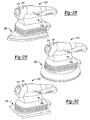
- the platens are shown as a finishing sander platen 520 ( fig. 28 ), a random orbit sander platen 522 ( Fig. 29 ) and a square finishing sander platen 524 ( Fig. 32 ).
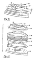
- the sander 510 provides elastomeric bellows 528 for securing a respective platen 520, 522, 524 to the tool body 512.
- the elastomeric bellows 528 is shown coupled between a plate 530 having a fan shroud 532 and an exemplary finishing sander platen 520.
- the fan shroud 532 can generally bound a fan 534 adapted for cooling the motor.
- the plate 530 can further define a dust chute 536 that is configured to exhaust air through a dust extraction chute (such as dust extraction chute 20).
- the elastomeric bellows 528 can couple between a pair of hose clips 560.
- the hose clips 560 can couple on opposite ends to the plate 530 and a securing plate 562.
- the securing plate 562 can define bosses 566 for selectively receiving pegs 568 formed on the finishing sander platen 520.
- the elastomeric bellows 528 provides an enclosure for effective dust extraction.
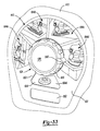
- the mode selector 624 can be operably disposed on a tool body 612 and can include a movable member 630, a control panel 632, a wheel 634 ( Fig. 34 ) and a central hub 636.
- the movable member 630 can be in the form of a dial or knob.
- the movable member 630 can have an indicator 640 formed thereon.
- the control panel 632 can include a pictorial key 642 that includes graphics in a first zone 644a, a second zone 644b, a third zone 644c and a fourth zone 644d.
- the movable member can be configured to rotate, such that the indicator 640 is aligned with a preferred graphic on the pictorial key 642 according to the desired sanding task.
- the control panel 632 can also define an opening 648, a window 650 and a button passage 652.
- the control panel 632 can also define recesses 654 adjacent to the opening 648 for selectively receiving a cap 658 that is biased by a spring 660 in a nested position.
- the biased cap 658 can give a user positive tactile feedback that the movable member 630 is located at the desired position aligned with a respective zone 644a-644d of the pictorial key 642.
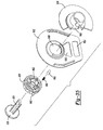
- a stem 661 of the central hub 636 locates through an opening 662 formed in the movable member 630, through the opening 648 in the control panel 632 and couples with a hub 663 on the wheel 634.
- the movable member 630, the central hub 636 and the wheel 634 can then collectively rotate relative to the opening 648 of the control panel 632.
- the wheel 634 can include a first image 664a, a second image 664b, a third image 664c, and a fourth image 664d.
- the wheel 634 is fixed for rotation with the movable member 630, such that one of the first through fourth images 664a-664d can be viewable through the window 650.
- the images 664a-664d correspond with the appropriate graphic 644a-644d on the pictorial key 642 according to the desired task identified by the user.
- a user can rotate the movable member 630 from the location shown in Fig. 36 to the location shown in Fig. 37 when it is desired to change the sanding task. While not expressly described here, rotation of the movable member 630 can cooperate with a speed control switch, such as the speed control switch 188 to correspond with first and second speeds of the motor as described above in relation to Figs. 20-22 .
- the movable member 630 is shown rotated to a location, such that the indicator 640 is pointing at the fourth zone 644d.
- a button 653 constructed similar to the button 30 described above is shown extending through the button passage 652. Because the movable member 630 is rotatably fixed with the wheel 634, this position corresponds to the fourth image 664d of the wheel 634 to be viewable through the window 650 of the control panel 632.
- the user can rotate the movable member, such as in a counterclockwise direction until the indicator 640 is pointing at the second zone 644b of the pictorial key 642. In this position, the second image 664b is viewable through the window 650 of the control panel 632.
- the first image 664a of the wheel 634 will be viewable through the window 650 when the indicator 640 is pointing at the first zone 644a of the pictorial key 642.
- the third image 644c of the wheel 634 will be viewable through the window 650 of the control panel 632 when the indicator 640 is pointing at the third zone 644c of the pictorial key 642.
- the respective images 664a-664d can be provided with different colors indicating that some of the selected modes of sanding can include a change in motor speed. It is also appreciated that the mode selector 624 and related features can be configured for operation with any of the sanders described herein.
Abstract
Description
- The present invention relates to a sander or other power tool for moving an abrasive medium, having a plurality of platens that can be selectively attached to a common base, preferably without the use of a hand tool.
- Sanders typically have a platen to which an abrasive medium, such as sandpaper, is attached. Sanders with removable, differently shaped platens (e.g., rectangular, square, round) are available to permit the user of the sander to change the platen to one with a shape that is best suited for a given sander task. Such removable platens typically are secured to the sander by way of one or more threaded fasteners (e.g., socket head cap screws). These threaded fasteners require the use of tools (e.g., Allen wrenches) to remove them from the sander to thereby decouple the platen from the sander.
- Various tool-less coupling systems have been developed for coupling a platen to the rotating output member of a rotary grinder. Such coupling systems, however are relatively large and costly and do not support an abrasive medium in an area where one element of the coupling system is received against the platen.
- According to a first aspect of the present invention, there is provided a power tool for moving an abrasive medium, comprising a tool body and a drive system housed in the tool body, the drive system including an output member. A retaining member may be disposed on the tool body. A first platen having a first attachment hub may be selectively coupled with the retaining member in an installed position. The first platen may have a first rotatable member that selectively attaches to the output member in a first mode of operation. A second platen having a second attachment hub may selectively couple with the retaining member in an installed position. The second platen may have a second rotatable member that selectively attaches to the output member in a second mode of operation.
- A mode selector may be disposed on the tool body. The mode selector may have a movable member, and preferably has a visible key, for example a pictorial or other symbolic key (e.g. one or more letters and/or numbers and/or images). The movable member may be movable between at least a first position that corresponds to a first output member speed and a second position that corresponds to a second output member speed. The movable member may be substantially aligned with a first graphic (i.e. symbol or set of symbols) on the visible key that corresponds to the first platen in the first position and second graphic on the visible key that corresponds to the second platen in the second position.
- A second aspect of the invention provides a power tool for moving an abrasive medium, comprising: a tool body; a drive system housed in the tool body and including an output member; a retaining member disposed on the tool body; a first platen having a first attachment hub that selectively couples with the retaining member in an installed position, the first platen having a first rotatable member that selectively attaches to the output member in a first mode of operation; a second platen having a second attachment hub that selectively couples with the retaining member in an installed position, the second platen having a second rotatable member that selectively attaches to the output member in a second mode of operation; and a mode selector disposed on the tool body and having a movable member, wherein the movable member is movable between at least a first position in which the first platen is used in the first mode of operation at a first output member speed and a second position in which the second platen is used (instead of the first platen) in the second mode of operation at a second output member speed.
- As indicated above, the movable member preferably is substantially aligned with a first graphic (i.e. symbol or set of symbols) that corresponds to the first platen when the movable member is in the first position, and preferably is substantially aligned with a second graphic that corresponds to the second platen when the movable member is in the second position. In this way, the user knows when to use the first platen, and when to use the second platen.
- According to other preferred features, the first rotatable member of the first platen may be mounted for an orbit having a first offset relative to the output member. The second rotatable member of the second platen may be mounted for an orbit having a second offset relative to the output member. The first and second offsets may be distinct. The first rotatable member may include a first fan having a first counterbalance disposed thereon. The second rotatable member may comprise a second fan having a second counterbalance disposed thereon. The first and second counterbalances may have distinct masses. In one example, the first platen may be an orbital platen configured for orbital sanding in the installed position and the second platen may be a random orbit platen configured for random orbit sanding in the installed position. The first platen may, for example, comprise a plurality of flexible columns having first ends coupled to the first platen and second ends that are selectively retained by the tool body in the installed position.
- According to additional preferred features, the retaining member may comprise a wireframe that selectively nests in respective grooves defined around each of the first and second attachment hubs respectively in the installed position. A button or other actuator may be disposed on the tool body. The actuator may cooperate with the wireframe and be movable to a release position to spread the wireframe and release the wireframe from the respective grooves to exchange between the first and second platens. According to one example, a chamfered annular leading edge is defined on each of the first and second attachment hubs respectively. Movement of a respective first or second platen to the installed position may cause the annular leading edge to spread the wireframe until continued movement toward the installed position causes the wireframe to nest in the respective grooves.
- According to still other preferred features, the tool may include a third platen having a third attachment hub that selectively couples with the retaining member in an installed position. The third platen may have a third rotatable member that selectively attaches to the output member in a third mode of operation. The first platen may define an iron-shaped profile having a substantially flat first end and a substantially pointed second end. The first platen may comprise a dust chute arranged proximate to the substantially pointed second end. The third platen may define an iron-shaped profile having a substantially pointed first end and a substantially flat second end. The third platen may comprise a dust chute arranged proximate to the substantially flat second end. The substantially flat first end of the first platen is aligned with a forward end of the tool in the installed position and the substantially pointed first end of a third platen is aligned with a forward end of the tool in the installed position.
- According to still other preferred features, the tool may comprise a speed control switch that communicates with the mode selector. The mode selector may define a rib that cams across an input of the speed control switch upon movement of the mode selector to toggle between the first output member speed and the second output member speed.
- A third aspect of the invention provides a method of selecting an appropriate operating rotational speed and abrading platen (e.g. sanding platen) of a powered abrading tool (e.g. a sander), including providing the tool with a tool body, a drive system and first and second platens. The tool body may have a mode selector including a movable member and a visible key, for example a pictorial or other symbolic key (e.g. one or more letters and/or numbers and/or images). The drive system can have an output member. The method preferably further includes moving the movable member to one of a first position or a second position. The first position may correspond to a graphic (i.e. a symbol or set of symbols) on the visible key illustrating the first platen and associated with a first output member speed and the second position corresponding to a graphic (i.e. a symbol or set of symbols) on the visible key illustrating the second platen and associated with a second output member speed. The method may further include, mounting one of the first or second platen to the tool body according to the selected first or second position.
- According to additional preferred features, the method may include rotating a dial causing a rib defined on the dial to cam across an input of a speed control switch and change the speed of the output member between a first and second output member speed. According to one example of the method, mounting one of the first or second platens to the tool body may include urging an attachment hub associated with a respective first or second platen into engagement with a wireframe retaining member disposed on the tool body. The method further includes, urging the attachment hub into engagement with the wireframe retaining member, such that the wireframe retaining member rides over a chamfered annular leading edge defined on the attachment hub and spreads outwardly until the wireframe retaining member nests at least partially around the selected attachment hub in a groove defined on the selected attachment hub.
- Embodiments of the invention will now be described, by way of example, with reference to the accompanying drawings, of which:
-
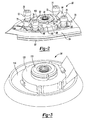
Fig. 1 is a front perspective view of an exemplary sander constructed in accordance to the present teachings and shown operatively associated with a series of sander platens that can be interchangeably secured to the sander,Fig. 1 also including an enlarged plan view of an exemplary mode selector provided on the sander; -
Fig. 2 is a side perspective view of an exemplary finishing sander platen; -
Fig. 3 is a side perspective view of an exemplary random orbit sander platen; -
Fig. 4 is a partial cut-away view of the sander and shown with the detail sander platen aligned prior to engagement with the tool body of the sander; -
Fig. 5 is a partial cut-away view of the sander ofFig. 4 and shown with the detail sander platen selectively coupled to the tool body of the sander; -
Fig. 6 is an exemplary plan view of a rotatable member having a fan and a counterweight and constructed in accordance to one example of the present teachings; -
Fig. 7 is a plan view of another rotatable member including a fan and a counterweight constructed in accordance to additional features of the present disclosure; -
Fig. 8 is a side perspective view of an exemplary random orbit sander platen and shown with a dual-outlet shroud according to one example of the present disclosure; -
Fig. 9 is a partial cut-away view of the tool body of the sander and shown prior to engagement with a platen having the dual shroud; -
Fig. 10 is an assembled view of an exemplary sander platen having the dual-outlet shroud and connected to the tool body of the sander, wherein one of the outlets is aligned for coupling with a plug and the other outlet is aligned for communicating air through a dust extraction port formed in the tool body; -
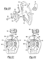
Figs. 11-14 illustrate an exemplary assembly sequence wherein an attachment assembly selectively couples with an attachment hub provided on an exemplary sander platen; -
Figs. 15 and 16 illustrate an exemplary sequence of releasing a sander platen from the tool body wherein a button of the attachment assembly is actuated causing a wireframe to spread and therefore release from engagement with a groove defined on the attachment hub; -
Figs. 17-19 illustrate an exemplary sequence of releasing a sander platen from the tool body wherein the button is actuated causing release of the wireframe from the groove defined in the attachment hub; -
Fig. 20 is an exploded perspective view of the mode selector ofFig. 1 ; -
Fig. 21 is a rear perspective view of a control panel of the mode selector ofFig. 20 and shown cooperating with a speed control switch; -
Fig. 22 is a rear perspective view of the control panel ofFig. 21 and shown with the speed control switch and electrical communication with an on/off switch; -
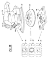
Fig. 23 is a side perspective view of a sander constructed in accordance to additional features of the present teachings; -
Fig. 24 is a front perspective view of a pair of exemplary sander platens that include nubs that selectively communicate with a first and second plurality of notches provided on the sander for coupling a desired platen to the tool body of the sander; -
Fig. 25 is a front perspective view of a sander constructed in accordance to additional features of the present teachings and shown operatively associated with a series of exemplary sander platens; -
Fig. 26 is a bottom perspective view of the sander ofFig. 25 and shown with an exemplary key for selectively attaching a desired platen to the tool body; -
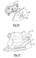
Fig. 27 is a front perspective view of a sander constructed in accordance to additional features of the present teachings and including a dust collection canister; -
Figs. 28-30 are front perspective views of sanders constructed in accordance to additional features of the present disclosure and including elastomeric bellows; -
Fig. 31 is a side perspective view of the exemplary sander platen ofFig. 28 and shown cooperating with elastomeric bellows for coupling the sander platen to the tool body; -
Fig. 32 is a side perspective exploded view of the bellows associated with the sander platen ofFig. 31 ; -
Fig. 33 is a front perspective view of a tool body and mode selector constructed in accordance to additional features of the present teachings; -
Fig. 34 is a front exploded view of the mode selector ofFig. 33 including a central hub, a knob, a control panel and a wheel; -
Fig. 35 is a rear perspective view of the mode selector ofFig. 34 ; -
Fig. 36 is a front view of the mode selector shown with the knob located in a fourth position revealing a fourth image of the wheel through a window formed in the control panel; and -
Fig. 37 is a front view of the mode selector illustrating the knob in a second position corresponding to the second image of the wheel being viewable through the window in the control panel. - Example embodiments will now be described more fully with reference to the accompanying drawings. Corresponding reference numerals indicate corresponding parts throughout the several views of the drawings.
- With initial reference to
Figs. 1-5 , an exemplary abrasive material removal tool is generally indicated byreference numeral 10. The abrasive material removal tool, hereinaftersander 10, can include a tool body orhousing 12 having a pair ofclam shell portions sander 10 can further include adrive system 18 that is housed in a cavity defined by theclam shell portions tool body 12 and thedrive system 18 can be conventional in their construction and operation, and as such, need not be discussed in significant detail herein. Thetool body 12 can further define a dust extraction port 20 (Fig. 4 ) to which dust can be extracted to adust chamber 21. Thedrive system 18 can selectively couple with a plurality of platens, collectively referred atreference numeral 22 as will be described in greater detail herein. - A
mode selector 24 can be arranged on a forward portion of thetool body 12. Themode selector 24 can include a movable member or dial 26 and apictorial key 28. Abase release button 30 can be provided proximate to themode selector 24. Apower cord 32 can extend from thetool body 12 to supply electrical current to thesander 10. It is appreciated that while thesander 10 is shown operatively associated with apower cord 32 for alternating current (AC) operation, thesander 10 can also be configured for operation with other power sources, such as direct current (DC) or a pneumatic input. - The
sander 10 will be further described. Thedrive system 18 can include an electric motor 36 (Fig. 4 ) mounted within thetool body 12 and having anoutput member 38. In the exemplary configuration, theoutput member 38 can define amale spline 40. A fan (not shown) can be mounted on theoutput member 38 for rotation therewith. The fan can include a plurality of upwardly projecting blades generally arranged to direct air toward themotor 36. In this manner, the upwardly projecting fan blades can operate to generate a cooling air flow when themotor 36 is turned on to help cool themotor 36 during operation of thesander 10. A bearing 44 can radially support theoutput member 38. - With specific reference now to
Figs. 1-7 , theexemplary platens 22 will be described in greater detail. According to the present teachings, each of the plurality ofplatens 22 can be releasably connected to thetool body 12 without the use of a hand tool (such as a screwdriver, Allen wrench, etc.). Theexemplary platens 22 can include a finishingsander platen 50, adetail sander platen 52, and a randomorbit sander platen 54. Thedetail sander platen 52 can include areleasable finger attachment 56 for detail sander. As will be described, the finishingsander platen 50 anddetail sander platen 52 are configured for orbital motion while the randomorbit sander platen 54 is configured for random orbit motion.U.S. Patent Nos. 6,132,300 and5,885,146 provide examples of abrading tools that provide orbital and random orbit motion. These patents are hereby incorporated by reference as is fully set forth in detail herein. - The finishing
sander platen 50 can define a substantiallyflat bottom surface 62, a curvedupper surface 64, and a peripheral edge with apoint 66 that provides the finishingsander platen 50 with an iron-shape. Thepoint 66 can be used for sander corners or other areas. In one example, an abrasive sheet (not shown) can be applied to theflat bottom surface 62 by way of a hook and loop fabric fastener. An underside of the abrasive sheet can have a first hook and/or loop surface, which can be attachable to a second hook and/or loop surface (not shown) provided on theflat bottom surface 62 of the finishingsander platen 50. - According to one example, a
portion 68 of the finishingsander platen 50, adjacent to thepoint 66 of the peripheral edge, can be detachable from the remainder of the finishingsander platen 50. Thedetachable portion 68 can be loosened or completely detached from the finishingsander platen 50 and rotated through 180°, or even replaced, as the edges on either side of the point become worn. Further details of thedetachable portion 68 can be found in commonly ownedU.S. Patent No. 5,839,949 , which is hereby incorporated by reference as if fully set forth in detail herein. As can be appreciated, thefinger attachment portion 56 of thedetail sander platen 52 can occupy the space of an otherwise located point 66 (i.e., see finishing sander platen 50). Those skilled in the art will readily appreciate that the shape and configuration of the finishingsander platen 50 anddetail sander platen 52 are substantially equivalent, the finishingsander platen 50 being configured for mounting to thetool body 12 with a flatforward end 70 facing toward the front of thesander 10, whereas thedetail sander platen 52, having thefinger attachment 56, can be secured to thetool body 12 having thefinger attachment 56 being oriented toward the forward end of thesander 10. Those skilled in the art will also appreciate that thedetail sander platen 52 can also be mounted to thesander 10 without thefinger attachment 56. - With specific reference to
Figs. 2 and4 , the finishingsander platen 50 can further define a plurality ofelastomeric legs 72. In the example shown, fourelastomeric legs 72 are used, one pair toward the front of thesander 10 and another pair disposed toward the rear of thesander 10. First ends 76 of theelastomeric legs 72 can be selectively received by mountinghubs 78 defined in the front and rearclam shell portions elastomeric legs 72 can be fixedly secured to the finishingsander platen 50 by mountingbosses 79. Other configurations may be employed for securing theelastomeric legs 72 between thetool body 12 and the finishingsander platen 50. - The finishing
sander platen 50 can further define a centrally locatedattachment hub 82 and achute 84. Theattachment hub 82 can generally house a rotatable member 88 (Fig. 6 ). Therotatable member 88 can generally be in the form of afan 90 having acounterweight 92. Thefan 90 can be configured to direct air through thechute 84 and into thedust extraction port 20. Therotatable member 88 can define a mountinghub 93 that aligns for rotation with afemale spline 94 that cooperatively receives themale spline 40 of theoutput member 38 in an installed position. The mountinghub 93 can be offset from acentral axis 98 of therotatable member 88. As can be appreciated, the offset can be any suitable distance to provide an orbital motion of the finishingsander platen 50 during operation. In one example, the offset can be 2mm. Other configurations are contemplated. For example, other finishing sander platens may be provided having other offsets. - With reference again to
Figs. 2 and4 , theattachment hub 82 can define a chamfered annularleading edge 100. Theattachment hub 82 can further define agroove 102 defined around a cylindrical outboard surface 104. Ashroud 106 can be defined on the finishingsander platen 50. Theshroud 106 can generally surround therotatable member 88. In one example, theattachment hub 82, thechute 84 and theshroud 106 can be monolithic or integrally formed. - As can be appreciated, the
detail sander platen 52 can be constructed similarly to the finishingsander platen 50. Therefore, a detailed description of thedetail sander platen 52 will not be repeated. As illustrated, however, a chute 84' (Fig. 1 ) can be arranged proximate to its rearward end (i.e., its flat end 70') for cooperatively aligning with thedust extraction port 20 provided in thetool body 12. An attachment hub 82' can house a rotatable member 88' (Fig. 1 ). - With specific attention now to
Figs. 3 and7 , the randomorbit sander platen 54 can generally define acircular platen body 114 having anattachment hub 116. Those skilled in the art will recognize that the randomorbit sander platen 54 is not constrained outboard of the attachment hub 116 (i.e., such as with elastomeric legs) allowing arandom orbit sander 54 to move in a motion during use. Theattachment hub 116 can be formed generally equivalent to theattachment hub 82 described above with respect to the finishingsander platen 50. Housed within theattachment hub 116 is a rotatable member 120 (Fig. 7 ). Therotatable member 120 can define asimilar mounting hub 93', fan 90' andcounterweight 92' arrangement as described above with respect to thefan 90,counterweight 92 and mountinghub 93. Therotatable member 120, however, can define a distinct offset (e.g. the mounting hub can be offset from its central axis) as compared to theorbit sander platens platens 22 can define mounting hubs (i.e., 93) that have an offset relative to a central axis of the rotatable member (i.e., 88) for providing a desired offset according to a given application. It is also appreciated that each of the counterweights (i.e., 92) can be provided with a mass that is specific to a given platen (i.e., 50, 52 or 54). - Turning now to
Figs. 8-10 , ashroud 130 constructed in accordance to another example is shown. Theshroud 130 includes afirst chute 132 and asecond chute 134 formed thereon. Theshroud 130 can be integrally formed with anattachment hub 136. Theattachment hub 136 can be formed equivalently to theattachment hubs shroud 130, having first andsecond chutes dust extraction port 20 in either a forward mounted position (i.e., the pointed end aligned with the front of thesander 10 for an iron-shaped platen) or a rearward mounted position (i.e., the flat end arranged toward the front of the sander 10). In one example, aplug 140 can be provided in thetool body 12 for aligning with anunused chute plug 140 can be formed of a compliant material and be generally captured by one of, or both of theclam shell housings dust chute connector 144 can be interposed between the functioningchute dust extraction port 20. It is appreciated that theshroud 130 can be adapted for use with any of theplatens 22 disclosed herein. For example, theshroud 130 is shown inFig. 8 operatively associated with a circular random orbit sander platen, whereas theshroud 130 is shown inFigs. 9 and 10 cooperatively with an iron-shaped finishing sander platen. - With renewed reference now to
Figs. 4 and 5 , thesander 10 can include anattachment assembly 150 for releasably coupling therespective sander platens 22 to thetool body 12. Theattachment assembly 150 can generally include thebutton 30, a retaining member orwireframe 152 and a spreader block 154. In the exemplary embodiment, the retainingmember 152 is in the form of a wireframe. However, other configurations are contemplated. In general, thewireframe 152 can selectively nest with the groove (i.e., groove 102) of a respective attachment hub (i.e., attachment hub 82). - As mentioned above, the
attachment assembly 150 can selectively couple with an identifiedsander platen 22 without the use of a hand tool (such as a screwdriver or Allen key, etc.). An exemplary method of attaching the finishingsander platen 50 according to one example of the present teachings will now be described with reference toFigs. 4, 5 and11-19 . It is appreciated that attaching (and removing) other platens (i.e., 52 or 54) will be carried out similarly. At the outset, a user can generally align thefemale spline 94 of therotatable member 88 with themale spline 40 of the output member 38 (Fig. 4 ). Concurrently, a user can align the first ends 76 of thelegs 72 with therespective hubs 78 defined in thetool body 12. The user can then urge thetool body 12 downwardly (and/or the finishingsander platen 50 in a direction upward) as viewed inFig. 11 . During such motion, thewireframe 152 can slidably urge over the chamfered annularleading edge 100 of theattachment hub 82 causing thewireframe 152 to generally spread outwardly until thewireframe 152 "snaps" into the groove 102 (see sequence ofFigs. 11-14 ). Those skilled in the art will appreciate that thewireframe 152 can have spring-like characteristics, such that in its relaxed state, thewireframe 152 can occupy a nested position within thegroove 102 and therefore retain arespective sander platen 22. In one example, thewireframe 152 can be formed of a metallic material. Those skilled in the art will appreciate that theattachment assembly 150 and/or thewireframe 152 can be configured differently. During the advancement of theattachment hub 82 toward thetool body 12, the first ends 76 of thelegs 72 can nest into therespective hubs 78 defined in thetool body 12. - An exemplary method of releasing the finishing
sander platen 50 according to the present teachings will now be described. Again, it is appreciated that releasing other platens (i.e., 52 or 54) will be carried out similarly. A user can push thebase release button 30 inwardly (i.e., in a direction leftward as viewed inFig. 16 ). Movement of thebase release button 30 in a direction leftward (i.e., into the tool body 12) can cause the button to slide along thewireframe 152 and therefore urge an intermediate portion of thewireframe 152 to spread radially out of engagement with thegroove 102. With thewireframe 152 in a position clear from the groove 102 (Figs. 16 and19 ), a user can then pull the finishingsander platen 50 in a direction downward (i.e., in a direction along an axis defined by the female spline 94) and away from thetool body 12. - With reference now to
Figs. 1 and20-22 , themode selector 24 will be described in greater detail. Themode selector 24 can generally define acontrol panel 160 that rotatably supports themovable member 26 to abacking plate 162 by way of a threadedfastener 164 andwasher 166. Arear face 170 of thecontrol panel 160 can define a pair ofsupports 172 that mount a pair of detent springs 176, respectively. Thebacking plate 162 can define a plurality ofdepressions 180 formed around its annular surface. As will be described, the detent springs 176 can selectively nest within an aligned pair ofdepressions 180 to positively locate themovable member 26 at a desired operating location. Thebacking plate 162 can further define arib 182. Therib 182 can be aligned with atoggle bar 184 associated with aspeed control switch 188. According to one example, thetoggle bar 184 can toggle between a first and second position upon movement of therib 182 across thetoggle bar 184. As will be described, the first and second position can correspond to a first and second speed of the motor 36 (and therefore the output member 38). - An exemplary circuit associated with the
mode selector 24 will be described briefly. Thespeed control switch 188 can include adiode 192. Thespeed control switch 188 can be electrically connected to an on/offswitch 194 of thesander 10. In n one example, when thespeed control switch 188 is moved to the first or "on" position, current bypasses thediode 192 and thesander 10 runs at full speed. When thespeed control switch 188 is turned to the second or "off" position, the current is forced through thediode 192 and the voltage is dropped causing the motor 36 (and, as a result, theoutput member 38 to rotate at a reduced speed). - With reference again to
Fig. 1 , thepictorial key 28 of themode selector 24 will be described in greater detail. As shown, the pictorial key 28 can have a firstouter zone 200, a secondouter zone 202, and a thirdouter zone 204. In one example, each of the first, second and thirdouter zones outer zone 200 can include a graphic with a pictorial representation of thedetail sander platen 52. The secondouter zone 202 can have a graphical representation of the finishingsander platen 50. The thirdouter zone 204 can have a graphical representation of the randomorbit sander platen 54. In one example, each of the outer zones can be color-coded with a distinct color. In addition, a picture of a turtle can be provided on the firstouter zone 200 and a picture of a rabbit can be provided on the thirdouter zone 204. As can be appreciated, a rotational orientation of themovable member 26 pointing toward the thirdouter zone 204 can correspond with the first speed and with thetoggle bar 184 in the first position, such that thespeed control switch 188 is in the "on" position. Likewise, when themovable member 26 rotated to be pointed toward the firstouter zone 200, thetoggle bar 184 is toggled to the second position (via movement of therib 182 across the toggle bar 184) corresponding to thespeed control switch 188 in the "off" position. It is appreciated that additional speed settings may be provided according to the outer zones and/or the inner zones (described below). It is contemplated that a potentiometer could be implemented to control speed. - According to other examples, indicia can be arranged around the pictorial key 28 that correspond to a grit value of sand paper optimized for a given task. Additionally or alternatively, the pictorial key 28 can have a graphic (e.g. picture, sketch, photograph, etc.) that corresponds to an exemplary article for sander (i.e., a door, a table, a pedestal, etc.). The grit value and picture of the article to be sanded can be arranged as a first
inner zone 205, a secondinner zone 206, a thirdinner zone 207, a fourthinner zone 208 and a fifthinner zone 209. It can be appreciated that while themode selector 24 has been shown and described above in connection to amovable member 26 that rotates around an axis in the form of a dial or pointer, the mode selector can take alternate forms. For example, themode selector 24 can alternatively comprise a lever configured for linear movement or other configurations. - With reference now to
Figs. 23 and 24 , asander 210 constructed in accordance to another example of the present teachings is shown. Except as otherwise described, thesander 210 can comprise the features as discussed herein with respect to other sanders. Thesander 210 can generally include a tool body orhousing 212 having a pair ofclam shell portions sander 210 can further include adrive system 218 that is housed in a cavity defined by theclam shell portions tool body 212 and thedrive system 218 can be conventional in their construction and operation, and as such, need not be discussed in significant detail herein. Amode selector 224 can be rotatably coupled to thetool body 212. As with thetool 10 described above, thesander 210 can be configured for selectively mating with a plurality of platens 222. An underside of themode selector 224 can define a first plurality ofnotches 225 formed around anannular ring 226. The first plurality ofnotches 225 can cooperatively align with a second plurality ofnotches 227 defined in thetool body 212. Themode selector 224 can further define apictorial key 228 arranged therearound. Thepictorial key 228 can define similar graphical representations as described above with respect to thepictorial key 28. In themode selector 224, according to this example, however, thepictorial key 228 of themode selector 224 is rotated to align with anarrow 230 provided on thetool body 212. - The plurality of platens 222 can define a finishing
sander platen 250 and a randomorbit sander platen 254. Other platens may be provided. The detail sander platen 252 can define anattachment hub 260 that includes a series ofnubs 262 extending outwardly around ashroud 264 thereof. Afemale spline 268 can be provided on the finishingsander platen 250 and be configured for meshingly engaging a male spline 270 provided on an electric motor 272 of thedrive system 218. Thenubs 262 are configured for slidably aligning and inserting into corresponding first andsecond notches ring 226 of themode selector 224 and thetool body 212, respectively. As can be appreciated, the first plurality ofnotches 225 will be rotationally aligned with specific second plurality ofnotches 227 for accepting the correct platen 222 that corresponds with a given graphic provided on thepictorial key 228 aligning with thearrow 230. - The random
orbit sander platen 254 can includenubs 274 arranged around anattachment hub 276. Atongue 280 can extend outwardly adjacent from theattachment hub 276. Thetongue 280 can be configured to cooperatively nest in apocket 282 formed on thetool body 212. As illustrated, thenubs 274 are located at a radially distinct location around the attachment of 276 as compared to thenubs 262 arranged around theattachment hub 260. As can be appreciated, once a user rotates themode selector 224 to a location in which a graphic of thepictorial key 228 that illustrates the randomorbit sander platen 254 is aligned with thearrow 230, thenubs 274 cooperatively align with predetermined notches 225 (of thering 226 of the mode selector 224) and notches 227 (of the tool body 212). As can be appreciated, the rotational orientation of thenotches pictorial key 228 aligned with thearrow 230. Therefore, attachment of other sander platens 222 is precluded. - It is appreciated that while the above embodiment has been described in association with "notches" and "nubs" other geometries may be provided for selectively keying specific platens to the
tool body 212. - While not specifically shown, a rotatable member can be provided in the
respective attachment hubs sander 210, such as by way of an attachment assembly (seeattachment assembly 150 described above), or other methods of attachment. - Turning now to
Figs. 25 and26 , asander 310 according to another example, of the present teachings is shown. Except as otherwise described, thesander 310 can comprise the features as described in herein with respect to other sanders. Thesander 310 can include a tool body orhousing 312 having a pair ofclam shell portions sander 310 can further include adrive system 318 that is housed in a cavity defined by theclam shell portions tool body 312 and thedrive system 318 can be conventional in their construction and operation, and as such, need not be discussed in significant detail herein. Thedrive system 318 can selectively couple with a plurality of platens, collectively referred to a reference 322. Thesander 310 can include awindow 324 that provides viewing access to awheel 326. In one configuration, thewheel 326 can define apictorial key 328. Thepictorial key 328 can include afirst zone 330, asecond zone 332, and athird zone 334. Therespective zones - The platens 322 can include a finishing
sander platen 350, a randomorbit sander platen 354, and a square footprintdetail sander platen 356. According to one example, a finger, orother structure 360, such as shown on thedetail sander platen 356 can be provided for rotating thewheels 326 into a rotational position that corresponds to the zone (i.e., 330, 332, or 334) associated with the attached platen 322 being viewed through thewindow 324. In one example, aflip key 366 can extend from theoutput member 338 of thesander 310. Theflip key 366 can pass through thecorresponding opening 370, shown on the finishingsander platen 350 and rotated to a secured position to lock a given platen 322 relative to thetool body 312. While not specifically shown, a similar opening is defined on theother platens flip key 366 can also be provided on other sanders disclosed herein for securing other platens described herein. - Turning now to
Fig. 27 , asander 410 according to additional features of the present teachings is shown. Except as otherwise described, thesander 410 can comprise the features as described herein with respect to other sanders. Thesander 410 can be constructed similar to thesanders dust extraction fan 411 provided in acanister 413 of thetool body 412. Because adust extraction fan 411 is provided in acanister 413, a plurality of platens (i.e., such as 350, 354 and 356,Fig. 25 ) can include rotatable members tuned for each platen. As such, each rotatable member can define a counterweight mass and offset, but without a fan (i.e., thefan 90 described above in relation with the sander 10). - Turning now to
Figs. 28-30 , asander 510 constructed in accordance with additional features of the present teachings is shown. Except as otherwise described, thesander 510 can comprise the features as described herein with respect to other sanders. Thesander 510 can include a tool body orhousing 512 having a pair ofclam shell portions sander 510 can further include adrive system 518 that is housed in a cavity defined by theclam shell portions tool body 512 and thedrive system 518 can be conventional in their construction and operation, and as such, need not be discussed in significant detail. Thedrive system 518 can selectively couple with a plurality of platens. The platens are shown as a finishing sander platen 520 (fig. 28 ), a random orbit sander platen 522 (Fig. 29 ) and a square finishing sander platen 524 (Fig. 32 ). Thesander 510 provideselastomeric bellows 528 for securing arespective platen tool body 512. - As shown in
Fig. 29 , the elastomeric bellows 528 is shown coupled between aplate 530 having afan shroud 532 and an exemplaryfinishing sander platen 520. Thefan shroud 532 can generally bound afan 534 adapted for cooling the motor. Theplate 530 can further define adust chute 536 that is configured to exhaust air through a dust extraction chute (such as dust extraction chute 20). Referring toFig. 30 , the elastomeric bellows 528 can couple between a pair of hose clips 560. The hose clips 560 can couple on opposite ends to theplate 530 and a securingplate 562. In one example, the securingplate 562 can definebosses 566 for selectively receivingpegs 568 formed on the finishingsander platen 520. The elastomeric bellows 528 provides an enclosure for effective dust extraction. - Turning now to
Figs. 33-37 , amode selector 624 constructed in accordance to additional features of the present teachings will be described. Themode selector 624 can be operably disposed on atool body 612 and can include amovable member 630, acontrol panel 632, a wheel 634 (Fig. 34 ) and acentral hub 636. Themovable member 630 can be in the form of a dial or knob. Themovable member 630 can have anindicator 640 formed thereon. Thecontrol panel 632 can include apictorial key 642 that includes graphics in afirst zone 644a, asecond zone 644b, athird zone 644c and afourth zone 644d. As will become appreciated, the movable member can be configured to rotate, such that theindicator 640 is aligned with a preferred graphic on thepictorial key 642 according to the desired sanding task. Thecontrol panel 632 can also define anopening 648, awindow 650 and abutton passage 652. Thecontrol panel 632 can also definerecesses 654 adjacent to theopening 648 for selectively receiving acap 658 that is biased by aspring 660 in a nested position. Thebiased cap 658 can give a user positive tactile feedback that themovable member 630 is located at the desired position aligned with arespective zone 644a-644d of thepictorial key 642. In an assembled position, astem 661 of thecentral hub 636 locates through anopening 662 formed in themovable member 630, through theopening 648 in thecontrol panel 632 and couples with ahub 663 on thewheel 634. Themovable member 630, thecentral hub 636 and thewheel 634 can then collectively rotate relative to theopening 648 of thecontrol panel 632. - The
wheel 634 can include afirst image 664a, asecond image 664b, athird image 664c, and afourth image 664d. Thewheel 634 is fixed for rotation with themovable member 630, such that one of the first throughfourth images 664a-664d can be viewable through thewindow 650. Theimages 664a-664d correspond with the appropriate graphic 644a-644d on thepictorial key 642 according to the desired task identified by the user. Explained further, and as illustrated inFigs. 36-37 , a user can rotate themovable member 630 from the location shown inFig. 36 to the location shown inFig. 37 when it is desired to change the sanding task. While not expressly described here, rotation of themovable member 630 can cooperate with a speed control switch, such as thespeed control switch 188 to correspond with first and second speeds of the motor as described above in relation toFigs. 20-22 . - As illustrated in
Fig. 36 , themovable member 630 is shown rotated to a location, such that theindicator 640 is pointing at thefourth zone 644d. Also shown inFigs. 36 and 37 , abutton 653 constructed similar to thebutton 30 described above is shown extending through thebutton passage 652. Because themovable member 630 is rotatably fixed with thewheel 634, this position corresponds to thefourth image 664d of thewheel 634 to be viewable through thewindow 650 of thecontrol panel 632. In the example shown inFig. 37 , the user can rotate the movable member, such as in a counterclockwise direction until theindicator 640 is pointing at thesecond zone 644b of thepictorial key 642. In this position, thesecond image 664b is viewable through thewindow 650 of thecontrol panel 632. - While not specifically shown, those skilled in the art will appreciate that the
first image 664a of thewheel 634 will be viewable through thewindow 650 when theindicator 640 is pointing at thefirst zone 644a of thepictorial key 642. Similarly, thethird image 644c of thewheel 634 will be viewable through thewindow 650 of thecontrol panel 632 when theindicator 640 is pointing at thethird zone 644c of thepictorial key 642. According to additional examples, therespective images 664a-664d can be provided with different colors indicating that some of the selected modes of sanding can include a change in motor speed. It is also appreciated that themode selector 624 and related features can be configured for operation with any of the sanders described herein. - The foregoing description of embodiments of the invention has been provided for purposes of illustration and description. It is not intended to be exhaustive. Individual elements or features of a particular embodiment are generally not limited to that particular embodiment, but, where applicable, are interchangeable and can be used in a selected embodiment, even if not specifically shown or described. The same may also be varied in many ways. Such variations are not to be regarded as a departure from the invention, and all such modifications are intended to be included within the scope of the invention.
Claims (15)
- A power tool (10), (210), (310), (410), (510) for moving an abrasive medium, characterized in that it includes:a tool body (12), (212), (312), (412), (512) (612);a drive system (18), (218), (318), (518) housed in the tool body and including an output member (38), (338);a retaining member (152), disposed on the tool body;a first platen (50) having a first attachment hub (82) that selectively couples with the retaining member in an installed position, the first platen having a first rotatable member (94) that selectively attaches to the output member in a first mode of operation;a second platen (54) having a second attachment hub (116) that selectively couples with the retaining member in an installed position, the second platen having a second rotatable member (120) that selectively attaches to the output member in a second mode of operation; anda mode selector (24), (224), (624) disposed on the tool body and having a movable member (26), (224), (630), wherein the movable member is movable between at least a first position in which the first platen is used in the first mode of operation at a first output member speed and a second position in which the second platen is used in the second mode of operation at a second output member speed.
- A power tool according to claim 1, wherein the mode selector includes a visible key (28), (228), (642), and the movable member is substantially aligned with a first graphic (28), (228), (644a-644d) on the visible key that corresponds to the first platen when the movable member is in the first position, and the movable member is substantially aligned with a second graphic (28), (228), (644a-644d) on the visible key that corresponds to the second platen when the movable member is in the second position.
- A power tool according to claim 1 or claim 2, wherein the first rotatable member of the first platen is mounted for an orbit having a first offset relative to the output member and the second rotatable member of the second platen is mounted for an orbit having a second offset relative to the output member, wherein the first and second offsets are distinct.
- A power tool according to any preceding claim, wherein the first rotatable member comprises a first fan (90) having a first counterbalance (92) disposed thereon and wherein the second rotatable member comprises a second fan (120) having a second counterbalance (92') disposed thereon and wherein the first and second counterbalances have distinct masses.
- A power tool according to any preceding claim, wherein the first platen is an orbital platen configured for orbital sanding in the installed position and the second platen is a random orbital platen configured for random orbital sanding in the installed position.
- A power tool according to any preceding claim, wherein the first platen comprises a plurality of flexible columns (72) having first ends (80) coupled to the first platen and second ends (76) that are selectively retained by the tool body in the installed position.
- A power tool according to any preceding claim, wherein the retaining member comprises a wireframe that selectively nests in respective grooves (102) defined around each of the respective first and second attachment hubs in the installed position.
- A power tool according to claim 7, further comprising an actuator (30) disposed on the tool body, the actuator cooperating with the wireframe and movable to a release position to spread the wireframe and release the wireframe from the respective grooves to exchange between the first and second platens.
- A power tool according to claim 7 or claim 8, wherein a chamfered annular leading edge (100) is defined on each of the first and second attachment hubs respectively, wherein movement of a respective first or second platen to the installed position causes the annular leading edge to spread the wireframe until continued movement toward the installed position causes the wireframe to nest in the respective grooves.
- A power tool according to any preceding claim, in which the second platen has a different shape to that of the first platen.
- A power tool according to any preceding claim, further comprising a third platen (52) having a third attachment hub (82') that selectively couples with the retaining member in an installed position, the third platen having a third rotatable member (88') that selectively attaches to the output member in a third mode of operation.
- A power tool according to claim 11 when dependent upon claim 2, wherein the movable member is substantially aligned with a third graphic on the visible key that corresponds to the third platen when the movable member is in a third position.
- A power tool according to any preceding claim, further comprising a speed control switch (188) that communicates with the mode selector, arranged such that when the mode selector is moved between the first position and the second position, it causes a switching member of the speed control switch to move between a first setting defining the first output member speed and a second setting defining the second output member speed, respectively.
- A power tool according to any preceding claim, wherein the first and second graphics of the visible key comprise representations of the first and second platens respectively, and preferably the first and second graphics of the visible key further comprise representations of work surfaces suitable for sanding with the first and second platens respectively.
- A power tool according to claim 2 or any claim dependent thereon, wherein the mode selector comprises:a control panel (632) defining an opening (648) and a window (650), the movable member being at least partially received by the opening; anda wheel (634) having at least a first and a second image (664a-664d) thereon, the wheel being coupled for rotation with the movable member and aligning one of the first or second images for viewing through the window during rotation of the movable member to correspond with the alignment of an indicator (640) on the movable member with the first or second graphic on the visible key.
Priority Applications (1)
| Application Number | Priority Date | Filing Date | Title |
|---|---|---|---|
| EP16160202.4A EP3050672B1 (en) | 2008-08-20 | 2009-08-20 | Sander |
Applications Claiming Priority (2)
| Application Number | Priority Date | Filing Date | Title |
|---|---|---|---|
| US9041708P | 2008-08-20 | 2008-08-20 | |
| US12/540,189 US8172642B2 (en) | 2008-08-20 | 2009-08-12 | Multi-sander |
Related Child Applications (2)
| Application Number | Title | Priority Date | Filing Date |
|---|---|---|---|
| EP16160202.4A Division EP3050672B1 (en) | 2008-08-20 | 2009-08-20 | Sander |
| EP16160202.4A Division-Into EP3050672B1 (en) | 2008-08-20 | 2009-08-20 | Sander |
Publications (3)
| Publication Number | Publication Date |
|---|---|
| EP2156925A2 true EP2156925A2 (en) | 2010-02-24 |
| EP2156925A3 EP2156925A3 (en) | 2013-09-04 |
| EP2156925B1 EP2156925B1 (en) | 2016-05-18 |
Family
ID=41328574
Family Applications (2)
| Application Number | Title | Priority Date | Filing Date |
|---|---|---|---|
| EP16160202.4A Active EP3050672B1 (en) | 2008-08-20 | 2009-08-20 | Sander |
| EP09168250.0A Active EP2156925B1 (en) | 2008-08-20 | 2009-08-20 | Sander |
Family Applications Before (1)
| Application Number | Title | Priority Date | Filing Date |
|---|---|---|---|
| EP16160202.4A Active EP3050672B1 (en) | 2008-08-20 | 2009-08-20 | Sander |
Country Status (4)
| Country | Link |
|---|---|
| US (6) | US8172642B2 (en) |
| EP (2) | EP3050672B1 (en) |
| CN (1) | CN201579686U (en) |
| CA (1) | CA2676053C (en) |
Cited By (2)
| Publication number | Priority date | Publication date | Assignee | Title |
|---|---|---|---|---|
| EP2607016A3 (en) * | 2011-12-21 | 2014-09-03 | Makita Corporation | Sander |
| EP2548702A3 (en) * | 2011-07-18 | 2018-05-09 | Black & Decker Inc. | Multi-Head Power Tool with Reverse Lock-Out Capability |
Families Citing this family (27)
| Publication number | Priority date | Publication date | Assignee | Title |
|---|---|---|---|---|
| US8172642B2 (en) * | 2008-08-20 | 2012-05-08 | Black & Decker Inc. | Multi-sander |
| DE102010012024B4 (en) * | 2010-03-19 | 2015-05-28 | Festool Gmbh | Hand tool machine with a forced rotation eccentric gear |
| DE102010033602B4 (en) * | 2010-08-06 | 2021-11-18 | Mafell Ag | Grinding system |
| US9776315B2 (en) | 2011-11-11 | 2017-10-03 | Black & Decker Inc. | Power tool having interchangeable tool heads with an independent accessory switch |
| US9408513B2 (en) * | 2011-12-19 | 2016-08-09 | Carine Elen | Motorized scrubbing, buffing, and polishing tool |
| US10399218B2 (en) * | 2011-12-19 | 2019-09-03 | Carine Elen | Motorized scrubbing, buffing, and polishing tool |
| US9393658B2 (en) | 2012-06-14 | 2016-07-19 | Black & Decker Inc. | Portable power tool |
| USD734116S1 (en) * | 2012-06-27 | 2015-07-14 | Kwai Sun Oliver Wong | Replacement head for a hand-held sanding implement |
| US9032576B2 (en) * | 2012-12-19 | 2015-05-19 | Newton Medical, Llc | Apparatus with elliptical movement for microdermabrasion and topical delivery of treatments |
| EP2953515B1 (en) | 2013-02-08 | 2017-04-05 | Techtronic Floor Care Technology Limited | Battery-powered cordless cleaning system |
| US9956677B2 (en) | 2013-05-08 | 2018-05-01 | Black & Decker Inc. | Power tool with interchangeable power heads |
| CN109773635A (en) * | 2013-07-12 | 2019-05-21 | 南京德朔实业有限公司 | Hand-held sander |
| US9387578B2 (en) | 2013-10-28 | 2016-07-12 | Black & Decker Inc. | Handle arrangement for sander |
| USD741557S1 (en) | 2014-01-15 | 2015-10-20 | Milwaukee Electric Tool Corporation | Dust collector |
| USD742081S1 (en) | 2014-01-15 | 2015-10-27 | Milwaukee Electric Tool Corporation | Dust collector |
| US9751176B2 (en) | 2014-05-30 | 2017-09-05 | Black & Decker Inc. | Power tool accessory attachment system |
| US10286516B2 (en) * | 2015-10-15 | 2019-05-14 | Makita Corporation | Polishers |
| WO2018001284A1 (en) | 2016-06-28 | 2018-01-04 | 苏州宝时得电动工具有限公司 | Sanding machine, operating method thereof and working baseplate disassembly-assembly method |
| US10020629B1 (en) * | 2017-07-13 | 2018-07-10 | Adam Michael Wise | Hotstick tool for assisting linemen tapping high power lines using wedge tap connectors |
| CN113043133B (en) * | 2017-08-04 | 2022-10-14 | 苏州宝时得电动工具有限公司 | Polishing tool |
| CN107855926A (en) * | 2017-12-07 | 2018-03-30 | 金翰阳科技(大连)股份有限公司 | Polishing machine tool Workpiece exchanging apparatus |
| CN209868288U (en) * | 2018-01-15 | 2019-12-31 | 苏州宝时得电动工具有限公司 | Polishing tool |
| USD910396S1 (en) * | 2018-09-24 | 2021-02-16 | 3M Innovative Properties Company | Attachment for a sanding device |
| CN110919555B (en) * | 2019-12-19 | 2024-04-16 | 宋京新 | Outer-rotating inner-cooling interchangeable electroplating cup type grinding wheel |
| US20210196322A1 (en) * | 2019-12-27 | 2021-07-01 | Candace Fletcher | Foot Sander Assembly |
| USD974869S1 (en) * | 2021-03-08 | 2023-01-10 | Photonix Corp | Cutting tool |
| CN114888680B (en) * | 2022-05-09 | 2023-06-06 | 常州赛迪工具有限公司 | Quick-change bottom plate of sander and multifunctional sander |
Citations (3)
| Publication number | Priority date | Publication date | Assignee | Title |
|---|---|---|---|---|
| US5839949A (en) | 1995-10-04 | 1998-11-24 | Black & Decker Inc. | Sander with multiple-layered platen |
| US5885146A (en) | 1995-12-06 | 1999-03-23 | Black & Decker Inc. | Oscillating hand tool |
| US6132300A (en) | 1994-07-26 | 2000-10-17 | Black & Decker Inc. | Dual function oscillating tool |
Family Cites Families (168)
| Publication number | Priority date | Publication date | Assignee | Title |
|---|---|---|---|---|
| US1965669A (en) | 1932-08-12 | 1934-07-10 | James C Robb | Portable electric tool |
| US2713271A (en) | 1951-07-17 | 1955-07-19 | Mall Tool Company | Motion converting means |
| US2898616A (en) | 1955-01-28 | 1959-08-11 | Kay Busser | Brush holder for waxing and polishing machines |
| US2795901A (en) * | 1955-07-28 | 1957-06-18 | Bruce H Mosbacher | Rubbing and abrading machines |
| US2893175A (en) * | 1957-12-19 | 1959-07-07 | American Lincoln Corp | Surfacing machine |
| US3525912A (en) | 1966-03-28 | 1970-08-25 | Scovill Manufacturing Co | Selectable power source for a motor driven appliance |
| US3390412A (en) * | 1966-06-22 | 1968-07-02 | Sunbeam Corp | Shoe polisher |
| JPS4812852Y1 (en) | 1968-01-20 | 1973-04-07 | ||
| US3533193A (en) * | 1968-11-25 | 1970-10-13 | Singer Co | Dual motion pad sanders |
| DE1938350A1 (en) * | 1969-07-29 | 1971-02-11 | Stoll Kg Kurt | Hand grinder |
| US3724237A (en) | 1971-06-07 | 1973-04-03 | Black & Decker Mfg Co | Attachment coupling for power tool |
| US3747594A (en) | 1971-11-19 | 1973-07-24 | Dormeyer A F Mfg Co | Portable electric appliance |
| US3761663A (en) | 1971-12-08 | 1973-09-25 | Cutler Hammer Inc | Trigger switch with selective two-position trigger-depression limiting means |
| US3759336A (en) | 1972-01-21 | 1973-09-18 | D Marcovitz | Interchangeable power operated tools |
| US3793776A (en) | 1972-07-21 | 1974-02-26 | Black & Decker Mfg Co | Double insulated portable sander |
| US3841416A (en) * | 1972-08-15 | 1974-10-15 | Black & Decker Mfg Co | Portable jig-saw and spindle sander |
| DE2316286A1 (en) * | 1973-03-31 | 1974-10-17 | Bosch Gmbh Robert | ORBITAL GRINDER |
| US3908139A (en) | 1974-06-10 | 1975-09-23 | Singer Co | Portable power tools |
| US3952239A (en) | 1974-08-23 | 1976-04-20 | The Black And Decker Manufacturing Company | Modular cordless tools |
| US3899852A (en) | 1974-08-23 | 1975-08-19 | Singer Co | Spindle drive assembly for a surface-treating machine |
| US3973179A (en) | 1974-08-23 | 1976-08-03 | The Black And Decker Manufacturing Company | Modular cordless tools |
| US4050528A (en) | 1975-09-05 | 1977-09-27 | Concept, Inc. | Wire inserter |
| US4091880A (en) | 1975-10-17 | 1978-05-30 | Concept Inc. | Surgical wire inserter apparatus |
| USRE30680E (en) | 1976-10-04 | 1981-07-21 | Firma Kress Elektrik Gmbh & Co. | Connecting arrangement for a machine tool |
| US4103511A (en) | 1976-10-04 | 1978-08-01 | Firma Kress Elektrik Gmbh & Co. | Connecting arrangement for a machine tool |
| US4052824A (en) * | 1976-11-29 | 1977-10-11 | Hutchins Manufacturing Company | Abrading tool suction system |
| US4125339A (en) | 1977-06-29 | 1978-11-14 | Pittinger Sr Charles B | Releasably interlocked, assymmetrical, lugged flange joint with fixed relative orientation |
| DE2748502B2 (en) | 1977-10-28 | 1979-08-30 | Licentia Patent-Verwaltungs-Gmbh, 6000 Frankfurt | Power tool with electrical speed measurement by means of a tachometer generator |
| DE2852327A1 (en) | 1978-12-04 | 1980-06-26 | Robert Wolff | SCREW-ON CLAMP NECK FOR NECKLESS ELECTRIC HAND DRILLING MACHINES |
| IT1163681B (en) | 1979-06-28 | 1987-04-08 | Star Utensili Elett | SPEEDOMETER GENERATOR |
| DE2933355A1 (en) | 1979-08-17 | 1981-03-26 | Scintilla Ag, Solothurn | ELECTRIC HAND TOOL |
| US4307325A (en) | 1980-01-28 | 1981-12-22 | Black & Decker Inc. | Digital control system for electric motors in power tools and the like |
| EP0033161B1 (en) | 1980-01-28 | 1985-04-17 | Black & Decker Inc. | Method and control circuit for temperature monitoring of an electric motor |
| US4304071A (en) | 1980-02-08 | 1981-12-08 | Poma 2.000 S.A | Safety device for sliding doors |
| DE3012637C2 (en) | 1980-04-01 | 1984-06-28 | Metabowerke GmbH & Co, 7440 Nürtingen | Electric motor-driven hand tool with a slip clutch |
| US4504769A (en) | 1980-10-28 | 1985-03-12 | Makita Electric Works, Ltd. | Electrically-powered tool |
| EP0086114A1 (en) | 1982-02-10 | 1983-08-17 | Hitachi Koki Co., Ltd. | Electrical tool having speed control circuit |
| US4513381A (en) * | 1982-06-07 | 1985-04-23 | The Singer Company | Speed regulator for power tool |
| JPS59163608A (en) * | 1983-03-08 | 1984-09-14 | Hitachi Koki Co Ltd | Jigsaw |
| FR2568377A1 (en) | 1984-07-25 | 1986-01-31 | Jouan | Hall-effect speed sensor built into a rotating machine. |
| JPS6161761A (en) * | 1984-08-29 | 1986-03-29 | Makita Denki Seisakusho:Kk | Cordless polishing machine |
| DE3518984A1 (en) * | 1985-05-25 | 1986-11-27 | Festo KG, 7300 Esslingen | BALANCED ORBIT SANDER |
| DE3538225C2 (en) | 1985-10-26 | 1997-08-14 | Wilo Gmbh | Centrifugal pump or fan |
| GB8529006D0 (en) | 1985-11-25 | 1986-01-02 | Highgate D J | Hydrophilic materials |
| US4728942A (en) | 1985-12-09 | 1988-03-01 | The Scott & Fetzer Company | Self-powered rotation indicator |
| DE3615799C2 (en) * | 1986-05-10 | 1994-10-13 | Bosch Gmbh Robert | Eccentric sander with a device for changing the grinding movement |
| US4834596A (en) | 1987-11-23 | 1989-05-30 | T.M. Smith Tool International Corporation | Quick change spindle adaptor for tool holder |
| US4871629A (en) | 1988-02-04 | 1989-10-03 | Black & Decker Inc. | Latching arrangement for battery packs |
| US4835410A (en) | 1988-02-26 | 1989-05-30 | Black & Decker Inc. | Dual-mode corded/cordless system for power-operated devices |
| US4835409A (en) | 1988-02-26 | 1989-05-30 | Black & Decker Inc. | Corded/cordless dual-mode power-operated device |
| US4827552A (en) | 1988-03-14 | 1989-05-09 | Better Health Concepts, Inc. | Rotary electric toothbrush |
| US5018411A (en) | 1988-07-03 | 1991-05-28 | Padura Nathan P | Multiple-head tool |
| US4962681A (en) | 1988-11-09 | 1990-10-16 | Yang Tai Her | Modular manual electric appliance |
| DE3906549A1 (en) * | 1989-03-02 | 1990-09-06 | Bosch Gmbh Robert | Eccentric grinder |
| US5018314A (en) * | 1989-06-08 | 1991-05-28 | Makita Electric Works, Ltd. | Sander |
| CN2074697U (en) | 1989-10-30 | 1991-04-10 | 宋文广 | Hand polishing machine with load indicator |
| US5128783A (en) | 1990-01-31 | 1992-07-07 | Ois Optical Imaging Systems, Inc. | Diffusing/collimating lens array for a liquid crystal display |
| US4995148A (en) | 1990-03-30 | 1991-02-26 | Imta | Robotically controlled multi-task end effector |
| US5033552A (en) | 1990-07-24 | 1991-07-23 | Hu Cheng Te | Multi-function electric tool |
| US5241053A (en) | 1990-09-05 | 1993-08-31 | Takeda Chemical Industries, Ltd. | Fused proteins comprising glycoprotein gD of HSV-1 and LTB |
| DE59101383D1 (en) | 1991-01-16 | 1994-05-19 | Fein C & E | Portable grinder with quick clamping device. |
| US5149230A (en) | 1991-03-04 | 1992-09-22 | Nett Daniel R | Rotating dual attachment receptacle apparatus tool |
| DE4113641A1 (en) | 1991-04-26 | 1992-10-29 | Bosch Gmbh Robert | HAND MACHINE TOOL |
| DE4137385C2 (en) | 1991-11-14 | 1993-11-18 | Hilti Ag | Speed control device for a hand-held power tool and method for its production |
| DE4233729A1 (en) | 1992-10-07 | 1994-04-14 | Bosch Gmbh Robert | Eccentric disc grinder with grinding disc brake |
| DE4223107A1 (en) | 1992-07-14 | 1994-01-20 | Bosch Gmbh Robert | Surface grinding machine |
| US5398457A (en) * | 1992-12-11 | 1995-03-21 | Updegrave; Scott A. | Edge and corner sanding attachment |
| DE4300037C1 (en) | 1993-01-02 | 1994-04-21 | Raymond A & Cie | Releasable socket coupling device for pipe - has formed retaining edges onto rib with deformable guides for plug insertion |
| DE4303044A1 (en) | 1993-02-04 | 1994-08-11 | Bosch Gmbh Robert | Hand tool for surface processing |
| DE59400402D1 (en) | 1993-02-04 | 1996-08-14 | Bosch Gmbh Robert | Hand tool for surface processing |
| DE4314799C2 (en) * | 1993-05-05 | 1995-04-13 | Fein C & E | Power tool |
| GB9320181D0 (en) | 1993-09-30 | 1993-11-17 | Black & Decker Inc | Improvements in and relating to power tools |
| US5392568A (en) | 1993-12-22 | 1995-02-28 | Black & Decker Inc. | Random orbit sander having braking member |
| DE59410331D1 (en) * | 1994-02-03 | 2003-11-27 | Bosch Gmbh Robert | Hand tool for surface processing |
| US5580302A (en) | 1994-02-28 | 1996-12-03 | Black & Decker Inc. | Random orbit sander having air directing baffle |
| US5421053A (en) | 1994-04-28 | 1995-06-06 | Aar Corp. | Removable brush coupling |
| US5490683A (en) | 1994-07-27 | 1996-02-13 | Mednext Inc. | Tool shaft coupler |
| US6062575A (en) | 1994-07-27 | 2000-05-16 | Mednext, Inc. | Tool shaft coupler |
| US6270087B1 (en) | 1994-07-27 | 2001-08-07 | Mednext, Inc. | Tool shaft coupler |
| US5759094A (en) | 1995-02-09 | 1998-06-02 | Porter-Cable Corporation | In-line detail sander |
| DE19617572A1 (en) | 1996-05-02 | 1997-11-13 | Bosch Gmbh Robert | Electric hand grinder |
| US5715156A (en) | 1996-06-24 | 1998-02-03 | Yilmaz; G. George | Method and apparatus for providing AC or DC power for battery powered tools |
| DE19731949C2 (en) | 1996-07-26 | 2001-04-26 | Makita Corp | Screw conveyor in a continuously working screwdriver tool |
| US5888200A (en) | 1996-08-02 | 1999-03-30 | Stryker Corporation | Multi-purpose surgical tool system |
| US5771516A (en) | 1996-08-26 | 1998-06-30 | Huang; Chen Shu-Hsia | Exchangeable power hand tool |
| JPH10286772A (en) | 1997-04-09 | 1998-10-27 | Nikon Corp | Polishing tool, and grinding tool |
| GB9718337D0 (en) | 1997-08-30 | 1997-11-05 | Black & Decker Inc | Power tool |
| GB9718312D0 (en) | 1997-08-30 | 1997-11-05 | Black & Decker Inc | Power tool |
| GB9718305D0 (en) | 1997-08-30 | 1997-11-05 | Black & Decker Inc | Power tool |
| GB9718336D0 (en) | 1997-08-30 | 1997-11-05 | Black & Decker Inc | Power tool |
| GB9720721D0 (en) | 1997-10-01 | 1997-11-26 | Black & Decker Inc | Power Tool |
| DE69805150T2 (en) | 1997-12-03 | 2002-12-12 | Ykk Corp | Tool holder for portable oscillating grinder |
| GB9802587D0 (en) | 1998-02-07 | 1998-04-01 | Black & Decker Inc | Power tool |
| GB9804472D0 (en) | 1998-03-04 | 1998-04-29 | Black & Decker Inc | A switch lock-off mechanism |
| US6062960A (en) * | 1998-04-27 | 2000-05-16 | Ryobi North America, Inc. | Orbital tool |
| US5947804A (en) * | 1998-04-27 | 1999-09-07 | Ryobi North America, Inc. | Adjustable eccentricity orbital tool |
| GB9809030D0 (en) | 1998-04-29 | 1998-06-24 | Black & Decker Inc | Powered oscillating hand tool |
| DE19820873A1 (en) | 1998-05-09 | 1999-11-11 | Bosch Gmbh Robert | Electric hand tool esp. for use in grinding and/or sanding |
| US6039126A (en) | 1998-05-15 | 2000-03-21 | Hsieh; An-Fu | Multi-usage electric tool with angle-changeable grip |
| US6126370A (en) | 1998-07-22 | 2000-10-03 | Black & Decker Inc. | Removable tool holder |
| JP2000176818A (en) | 1998-12-21 | 2000-06-27 | Ykk Corp | Fixture for coated abrasive |
| US6296065B1 (en) | 1998-12-30 | 2001-10-02 | Black & Decker Inc. | Dual-mode non-isolated corded system for transportable cordless power tools |
| US7828630B2 (en) | 1999-02-08 | 2010-11-09 | Black & Decker Inc. | Tool body |
| US6243276B1 (en) | 1999-05-07 | 2001-06-05 | S-B Power Tool Company | Power supply system for battery operated devices |
| AU5701200A (en) | 1999-07-02 | 2001-01-22 | Petrus Besselink | Reinforced expandable cage |
| US6244933B1 (en) | 1999-07-07 | 2001-06-12 | Wolfgang Morkvenas | Random orbital finishing apparatus |
| US6104162A (en) | 1999-09-11 | 2000-08-15 | Sainsbury; Simon R. | Method and apparatus for multi-power source for power tools |
| US6286609B1 (en) | 1999-12-10 | 2001-09-11 | Black & Decker Inc. | AC/DC chopper for power tool |
| US6237698B1 (en) | 1999-12-10 | 2001-05-29 | Black & Decker Inc. | Terminal protection system for portable power tools |
| GB0005937D0 (en) | 2000-03-10 | 2000-05-03 | Black & Decker Inc | Interlock mechanism |
| GB0005821D0 (en) | 2000-03-10 | 2000-05-03 | Black & Decker Inc | Coupling method |
| GB0005822D0 (en) | 2000-03-10 | 2000-05-03 | Black & Decker Inc | Coupling mechanism |
| GB0005897D0 (en) | 2000-03-10 | 2000-05-03 | Black & Decker Inc | Power tool |
| JP2001300867A (en) | 2000-04-21 | 2001-10-30 | Makita Corp | Adapter for power tool |
| US6523214B1 (en) * | 2000-06-14 | 2003-02-25 | Richard A. Kaiser | Quick mount attachment for rotary finishing tool |
| NL1015488C2 (en) * | 2000-06-21 | 2001-12-28 | Skil Europ Bv | Orbital sander with interchangeable part of sanding sole. |
| US6613089B1 (en) | 2000-10-25 | 2003-09-02 | Sdgi Holdings, Inc. | Laterally expanding intervertebral fusion device |
| US6573621B2 (en) | 2000-12-01 | 2003-06-03 | S-B Power Tool Company | AC/DC power supply system for power tools |
| DE10104993A1 (en) * | 2001-02-03 | 2002-08-22 | Bosch Gmbh Robert | Hand tool for grinding, polishing or the like |
| CN1381336A (en) | 2001-04-17 | 2002-11-27 | 上海星特浩企业有限公司 | AC/DC exchangeable multi-purpose combined tool |
| US6601621B2 (en) | 2001-04-18 | 2003-08-05 | Black & Decker Inc. | Portable Power Planer |
| DE10124971B4 (en) | 2001-05-21 | 2013-06-20 | Hilti Aktiengesellschaft | Quick clamping device for a circular saw |
| GB2377662B (en) | 2001-07-20 | 2004-09-22 | Black & Decker Inc | Oscillating hand tool |
| GB2380151B (en) | 2001-07-20 | 2004-09-22 | Black & Decker Inc | Oscillating hand tool |
| US6494916B1 (en) | 2001-07-30 | 2002-12-17 | Biomed Solutions, Llc | Apparatus for replacing musculo-skeletal parts |
| US20030097178A1 (en) | 2001-10-04 | 2003-05-22 | Joseph Roberson | Length-adjustable ossicular prosthesis |
| US6889878B2 (en) * | 2001-11-08 | 2005-05-10 | Armament Systems And Procedures, Inc. | Baton carrier |
| US7048617B1 (en) | 2002-05-17 | 2006-05-23 | Spiva Neal A | Method and apparatus for smoothing unfinished surfaces |
| US7653963B2 (en) | 2002-11-12 | 2010-02-02 | Black & Decker Inc. | AC/DC hand portable wet/dry vacuum having improved portability and convenience |
| US20040220672A1 (en) | 2003-05-03 | 2004-11-04 | Shadduck John H. | Orthopedic implants, methods of use and methods of fabrication |
| US7270910B2 (en) | 2003-10-03 | 2007-09-18 | Black & Decker Inc. | Thermal management systems for battery packs |
| DE102004003203A1 (en) | 2004-01-22 | 2005-08-11 | Robert Bosch Gmbh | Electric hand tool with optimized working area |
| US20050221738A1 (en) | 2004-04-06 | 2005-10-06 | Cooper Vincent P | Orbital sander with vertical handle |
| ATE502725T1 (en) | 2004-04-13 | 2011-04-15 | Black & Decker Inc | ELECTRIC GRINDING MACHINE AND ITS MOTOR CONTROL |
| US7114824B2 (en) | 2004-05-03 | 2006-10-03 | Picone Products, Inc. | Multi-functional tool with interchangeable adjustable wrench head unit |
| US20060019585A1 (en) | 2004-07-26 | 2006-01-26 | Zayat Charles D | Device for circular grinding, sanding and stripping tools to attach to any power drive |
| US7220174B2 (en) | 2004-09-29 | 2007-05-22 | Black & Decker Inc. | Drywall sander |
| US7198559B2 (en) | 2004-12-23 | 2007-04-03 | Black & Decker, Inc. | Modular sander-casing architecture |
| US7384173B2 (en) | 2004-12-30 | 2008-06-10 | 3M Innovative Properties Company | Brightness enhancement article |
| US7235005B2 (en) | 2005-03-24 | 2007-06-26 | Black & Decker Inc. | Belt sander |
| US7649337B2 (en) | 2005-05-17 | 2010-01-19 | Milwaukee Electric Tool Corporation | Power tool including a fuel gauge and method of operating the same |
| DE102005045310B3 (en) * | 2005-09-16 | 2007-03-22 | Alfred Kärcher Gmbh & Co. Kg | Mobile floor cleaning machine |
| US7775855B2 (en) * | 2005-12-29 | 2010-08-17 | 3M Innovative Properties Company | Sanding tool with rotatable handle |
| US20090010725A1 (en) | 2006-03-01 | 2009-01-08 | Robatti Aps | Turret head hand-held drilling machine/driver |
| US7743683B2 (en) | 2006-08-15 | 2010-06-29 | Umagination Labs, L.P. | Systems and methods of a power tool system with interchangeable functional attachments powered by a direct rotational drive |
| US7913345B2 (en) | 2006-08-15 | 2011-03-29 | Umagination Labs, L.P. | Systems and methods of a power tool system with interchangeable functional attachments |
| US7926141B2 (en) | 2006-08-15 | 2011-04-19 | Umagination Labs, L.P. | Systems and methods of a gutter cleaning system |
| US7713110B2 (en) * | 2006-09-05 | 2010-05-11 | Dynabrade, Inc. | Locking random orbital dual-action head assembly |
| DE102006045157B4 (en) | 2006-09-25 | 2020-06-18 | Robert Bosch Gmbh | Hand tool |
| DE102006048315A1 (en) | 2006-10-12 | 2008-04-17 | Robert Bosch Gmbh | Hand tool, in particular electric scissors |
| US7568867B2 (en) | 2006-10-18 | 2009-08-04 | Bryan Steve M | Air driven spindle assembly |
| US7719230B2 (en) | 2006-10-27 | 2010-05-18 | Snap-On Incorporated | Kit of power tools |
| US7609025B2 (en) | 2006-11-03 | 2009-10-27 | Snap-On Incorporated | Kit of power tools |
| US7722435B2 (en) * | 2007-06-13 | 2010-05-25 | Black & Decker Inc. | Sander |
| US7825615B2 (en) | 2007-10-16 | 2010-11-02 | Glj, Llc | Intelligent motorized appliances with multiple power sources |
| US7770660B2 (en) | 2007-11-21 | 2010-08-10 | Black & Decker Inc. | Mid-handle drill construction and assembly process |
| US8172650B2 (en) * | 2008-03-18 | 2012-05-08 | Paul W. Huber | Automatic shift dual-action tool |
| US8172642B2 (en) | 2008-08-20 | 2012-05-08 | Black & Decker Inc. | Multi-sander |
| US7736216B2 (en) * | 2008-08-20 | 2010-06-15 | Black & Decker Inc. | Sander having removable platen |
| CN101992456B (en) | 2009-08-11 | 2013-02-06 | 泉峰(中国)贸易有限公司 | Electric tool |
| CN102049762B (en) | 2009-10-28 | 2012-08-22 | 南京德朔实业有限公司 | Electric hammer |
| CN201565933U (en) | 2009-10-30 | 2010-09-01 | 南京德朔实业有限公司 | Electric hammer |
| CN201525004U (en) | 2009-11-04 | 2010-07-14 | 南京德朔实业有限公司 | Electric hammer |
| CN201525005U (en) | 2009-11-05 | 2010-07-14 | 南京德朔实业有限公司 | Electric hammer |
| CN201659545U (en) | 2009-11-09 | 2010-12-01 | 南京德朔实业有限公司 | Electric hammer |
| CN201565934U (en) | 2009-11-06 | 2010-09-01 | 南京德朔实业有限公司 | Electric hammer |
| US20110121782A1 (en) | 2009-11-23 | 2011-05-26 | Marsh Douglas G | Powering a Cordless Drill from AC Line Power |
| EP2388107B1 (en) | 2009-12-18 | 2019-09-04 | Techtronic Power Tools Technology Limited | Multi-function tool system |
-
2009
- 2009-08-12 US US12/540,189 patent/US8172642B2/en active Active
- 2009-08-13 CA CA2676053A patent/CA2676053C/en not_active Expired - Fee Related
- 2009-08-20 EP EP16160202.4A patent/EP3050672B1/en active Active
- 2009-08-20 CN CN2009201798348U patent/CN201579686U/en not_active Expired - Fee Related
- 2009-08-20 EP EP09168250.0A patent/EP2156925B1/en active Active
-
2012
- 2012-05-07 US US13/465,631 patent/US8398457B2/en active Active
-
2013
- 2013-03-14 US US13/804,222 patent/US8613644B2/en active Active
- 2013-09-26 US US14/037,462 patent/US8821220B2/en active Active
-
2014
- 2014-04-16 US US14/254,440 patent/US9724799B2/en active Active
-
2017
- 2017-06-15 US US15/623,738 patent/US10906155B2/en active Active
Patent Citations (3)
| Publication number | Priority date | Publication date | Assignee | Title |
|---|---|---|---|---|
| US6132300A (en) | 1994-07-26 | 2000-10-17 | Black & Decker Inc. | Dual function oscillating tool |
| US5839949A (en) | 1995-10-04 | 1998-11-24 | Black & Decker Inc. | Sander with multiple-layered platen |
| US5885146A (en) | 1995-12-06 | 1999-03-23 | Black & Decker Inc. | Oscillating hand tool |
Cited By (3)
| Publication number | Priority date | Publication date | Assignee | Title |
|---|---|---|---|---|
| EP2548702A3 (en) * | 2011-07-18 | 2018-05-09 | Black & Decker Inc. | Multi-Head Power Tool with Reverse Lock-Out Capability |
| EP2607016A3 (en) * | 2011-12-21 | 2014-09-03 | Makita Corporation | Sander |
| US9114500B2 (en) | 2011-12-21 | 2015-08-25 | Makita Corporation | Sander having battery pack |
Also Published As
| Publication number | Publication date |
|---|---|
| CA2676053C (en) | 2015-09-29 |
| CA2676053A1 (en) | 2010-02-20 |
| CN201579686U (en) | 2010-09-15 |
| US8821220B2 (en) | 2014-09-02 |
| US8613644B2 (en) | 2013-12-24 |
| EP3050672A1 (en) | 2016-08-03 |
| EP3050672B1 (en) | 2017-07-05 |
| US20140024301A1 (en) | 2014-01-23 |
| US20120220203A1 (en) | 2012-08-30 |
| US8398457B2 (en) | 2013-03-19 |
| US20130196571A1 (en) | 2013-08-01 |
| US20140227948A1 (en) | 2014-08-14 |
| US20100048101A1 (en) | 2010-02-25 |
| US8172642B2 (en) | 2012-05-08 |
| US9724799B2 (en) | 2017-08-08 |
| EP2156925B1 (en) | 2016-05-18 |
| EP2156925A3 (en) | 2013-09-04 |
| US20170282328A1 (en) | 2017-10-05 |
| US10906155B2 (en) | 2021-02-02 |
Similar Documents
| Publication | Publication Date | Title |
|---|---|---|
| EP2156925B1 (en) | Sander | |
| EP0953407B1 (en) | Powered oscillating hand tool | |
| CN102152207B (en) | Electric power tool | |
| US10661407B2 (en) | Hand-held and hand-guided power tool having a working element releasably attached thereto, and for such a power tool | |
| US5709595A (en) | Power tool for surface treatment | |
| KR20090041444A (en) | Locking random orbital dual-action head assembly | |
| EP1166963B1 (en) | Plane sander with exchangeable part of sanding sole | |
| US20210205944A1 (en) | Rotating apparatus | |
| CN201300357Y (en) | Polisher and electric tool | |
| CN110039420B (en) | Polishing tool, and method for detaching and installing base plate assembly of polishing tool | |
| EP3132892B1 (en) | Multi-sander kit | |
| CN110944794B (en) | Sanding tool and main body part and sanding part thereof | |
| EP3015220A1 (en) | Power tool dust port connector mechanism | |
| CN100577359C (en) | Multifunctional sander | |
| JP7107554B2 (en) | dust cover | |
| US20090209182A1 (en) | Locking random orbital dual-action head assembly | |
| CN107791130B (en) | Multifunctional sander | |
| JP2020023006A (en) | Cover and tool | |
| JP2012206211A (en) | Dust collection adapter and power tool including dust collection adapter | |
| GB2268428A (en) | Orbital grinding apparatus | |
| CN113146437A (en) | Protective cover for a power tool of the manual type and power tool of the manual type | |
| JP2002046052A (en) | Polishing machine |
Legal Events
| Date | Code | Title | Description |
|---|---|---|---|
| PUAI | Public reference made under article 153(3) epc to a published international application that has entered the european phase |
Free format text: ORIGINAL CODE: 0009012 |
|
| AK | Designated contracting states |
Kind code of ref document: A2 Designated state(s): AT BE BG CH CY CZ DE DK EE ES FI FR GB GR HR HU IE IS IT LI LT LU LV MC MK MT NL NO PL PT RO SE SI SK SM TR |
|
| PUAL | Search report despatched |
Free format text: ORIGINAL CODE: 0009013 |
|
| AK | Designated contracting states |
Kind code of ref document: A3 Designated state(s): AT BE BG CH CY CZ DE DK EE ES FI FR GB GR HR HU IE IS IT LI LT LU LV MC MK MT NL NO PL PT RO SE SI SK SM TR |
|
| RIC1 | Information provided on ipc code assigned before grant |
Ipc: B24B 45/00 20060101ALI20130726BHEP Ipc: B24B 23/04 20060101ALI20130726BHEP Ipc: B24B 23/03 20060101AFI20130726BHEP |
|
| 17P | Request for examination filed |
Effective date: 20140303 |
|
| RBV | Designated contracting states (corrected) |
Designated state(s): AT BE BG CH CY CZ DE DK EE ES FI FR GB GR HR HU IE IS IT LI LT LU LV MC MK MT NL NO PL PT RO SE SI SK SM TR |
|
| 17Q | First examination report despatched |
Effective date: 20140822 |
|
| GRAP | Despatch of communication of intention to grant a patent |
Free format text: ORIGINAL CODE: EPIDOSNIGR1 |
|
| INTG | Intention to grant announced |
Effective date: 20150602 |
|
| GRAJ | Information related to disapproval of communication of intention to grant by the applicant or resumption of examination proceedings by the epo deleted |
Free format text: ORIGINAL CODE: EPIDOSDIGR1 |
|
| INTC | Intention to grant announced (deleted) | ||
| GRAP | Despatch of communication of intention to grant a patent |
Free format text: ORIGINAL CODE: EPIDOSNIGR1 |
|
| INTG | Intention to grant announced |
Effective date: 20160212 |
|
| GRAS | Grant fee paid |
Free format text: ORIGINAL CODE: EPIDOSNIGR3 |
|
| GRAA | (expected) grant |
Free format text: ORIGINAL CODE: 0009210 |
|
| AK | Designated contracting states |
Kind code of ref document: B1 Designated state(s): AT BE BG CH CY CZ DE DK EE ES FI FR GB GR HR HU IE IS IT LI LT LU LV MC MK MT NL NO PL PT RO SE SI SK SM TR |
|
| REG | Reference to a national code |
Ref country code: GB Ref legal event code: FG4D |
|
| REG | Reference to a national code |
Ref country code: CH Ref legal event code: EP |
|
| REG | Reference to a national code |
Ref country code: IE Ref legal event code: FG4D Ref country code: AT Ref legal event code: REF Ref document number: 800008 Country of ref document: AT Kind code of ref document: T Effective date: 20160615 |
|
| REG | Reference to a national code |
Ref country code: DE Ref legal event code: R096 Ref document number: 602009038701 Country of ref document: DE |
|
| REG | Reference to a national code |
Ref country code: FR Ref legal event code: PLFP Year of fee payment: 8 |
|
| REG | Reference to a national code |
Ref country code: NL Ref legal event code: MP Effective date: 20160518 |
|
| REG | Reference to a national code |
Ref country code: LT Ref legal event code: MG4D |
|
| PG25 | Lapsed in a contracting state [announced via postgrant information from national office to epo] |
Ref country code: NO Free format text: LAPSE BECAUSE OF FAILURE TO SUBMIT A TRANSLATION OF THE DESCRIPTION OR TO PAY THE FEE WITHIN THE PRESCRIBED TIME-LIMIT Effective date: 20160818 Ref country code: LT Free format text: LAPSE BECAUSE OF FAILURE TO SUBMIT A TRANSLATION OF THE DESCRIPTION OR TO PAY THE FEE WITHIN THE PRESCRIBED TIME-LIMIT Effective date: 20160518 Ref country code: FI Free format text: LAPSE BECAUSE OF FAILURE TO SUBMIT A TRANSLATION OF THE DESCRIPTION OR TO PAY THE FEE WITHIN THE PRESCRIBED TIME-LIMIT Effective date: 20160518 Ref country code: NL Free format text: LAPSE BECAUSE OF FAILURE TO SUBMIT A TRANSLATION OF THE DESCRIPTION OR TO PAY THE FEE WITHIN THE PRESCRIBED TIME-LIMIT Effective date: 20160518 |
|
| REG | Reference to a national code |
Ref country code: AT Ref legal event code: MK05 Ref document number: 800008 Country of ref document: AT Kind code of ref document: T Effective date: 20160518 |
|
| PG25 | Lapsed in a contracting state [announced via postgrant information from national office to epo] |
Ref country code: LV Free format text: LAPSE BECAUSE OF FAILURE TO SUBMIT A TRANSLATION OF THE DESCRIPTION OR TO PAY THE FEE WITHIN THE PRESCRIBED TIME-LIMIT Effective date: 20160518 Ref country code: SE Free format text: LAPSE BECAUSE OF FAILURE TO SUBMIT A TRANSLATION OF THE DESCRIPTION OR TO PAY THE FEE WITHIN THE PRESCRIBED TIME-LIMIT Effective date: 20160518 Ref country code: PT Free format text: LAPSE BECAUSE OF FAILURE TO SUBMIT A TRANSLATION OF THE DESCRIPTION OR TO PAY THE FEE WITHIN THE PRESCRIBED TIME-LIMIT Effective date: 20160919 Ref country code: GR Free format text: LAPSE BECAUSE OF FAILURE TO SUBMIT A TRANSLATION OF THE DESCRIPTION OR TO PAY THE FEE WITHIN THE PRESCRIBED TIME-LIMIT Effective date: 20160819 Ref country code: HR Free format text: LAPSE BECAUSE OF FAILURE TO SUBMIT A TRANSLATION OF THE DESCRIPTION OR TO PAY THE FEE WITHIN THE PRESCRIBED TIME-LIMIT Effective date: 20160518 Ref country code: ES Free format text: LAPSE BECAUSE OF FAILURE TO SUBMIT A TRANSLATION OF THE DESCRIPTION OR TO PAY THE FEE WITHIN THE PRESCRIBED TIME-LIMIT Effective date: 20160518 |
|
| PG25 | Lapsed in a contracting state [announced via postgrant information from national office to epo] |
Ref country code: BE Free format text: LAPSE BECAUSE OF NON-PAYMENT OF DUE FEES Effective date: 20160831 Ref country code: IT Free format text: LAPSE BECAUSE OF FAILURE TO SUBMIT A TRANSLATION OF THE DESCRIPTION OR TO PAY THE FEE WITHIN THE PRESCRIBED TIME-LIMIT Effective date: 20160518 |
|
| PG25 | Lapsed in a contracting state [announced via postgrant information from national office to epo] |
Ref country code: CZ Free format text: LAPSE BECAUSE OF FAILURE TO SUBMIT A TRANSLATION OF THE DESCRIPTION OR TO PAY THE FEE WITHIN THE PRESCRIBED TIME-LIMIT Effective date: 20160518 Ref country code: RO Free format text: LAPSE BECAUSE OF FAILURE TO SUBMIT A TRANSLATION OF THE DESCRIPTION OR TO PAY THE FEE WITHIN THE PRESCRIBED TIME-LIMIT Effective date: 20160518 Ref country code: SK Free format text: LAPSE BECAUSE OF FAILURE TO SUBMIT A TRANSLATION OF THE DESCRIPTION OR TO PAY THE FEE WITHIN THE PRESCRIBED TIME-LIMIT Effective date: 20160518 Ref country code: DK Free format text: LAPSE BECAUSE OF FAILURE TO SUBMIT A TRANSLATION OF THE DESCRIPTION OR TO PAY THE FEE WITHIN THE PRESCRIBED TIME-LIMIT Effective date: 20160518 Ref country code: EE Free format text: LAPSE BECAUSE OF FAILURE TO SUBMIT A TRANSLATION OF THE DESCRIPTION OR TO PAY THE FEE WITHIN THE PRESCRIBED TIME-LIMIT Effective date: 20160518 |
|
| REG | Reference to a national code |
Ref country code: DE Ref legal event code: R097 Ref document number: 602009038701 Country of ref document: DE |
|
| PG25 | Lapsed in a contracting state [announced via postgrant information from national office to epo] |
Ref country code: BE Free format text: LAPSE BECAUSE OF FAILURE TO SUBMIT A TRANSLATION OF THE DESCRIPTION OR TO PAY THE FEE WITHIN THE PRESCRIBED TIME-LIMIT Effective date: 20160518 Ref country code: PL Free format text: LAPSE BECAUSE OF FAILURE TO SUBMIT A TRANSLATION OF THE DESCRIPTION OR TO PAY THE FEE WITHIN THE PRESCRIBED TIME-LIMIT Effective date: 20160518 Ref country code: SM Free format text: LAPSE BECAUSE OF FAILURE TO SUBMIT A TRANSLATION OF THE DESCRIPTION OR TO PAY THE FEE WITHIN THE PRESCRIBED TIME-LIMIT Effective date: 20160518 Ref country code: AT Free format text: LAPSE BECAUSE OF FAILURE TO SUBMIT A TRANSLATION OF THE DESCRIPTION OR TO PAY THE FEE WITHIN THE PRESCRIBED TIME-LIMIT Effective date: 20160518 |
|
| PLBE | No opposition filed within time limit |
Free format text: ORIGINAL CODE: 0009261 |
|
| STAA | Information on the status of an ep patent application or granted ep patent |
Free format text: STATUS: NO OPPOSITION FILED WITHIN TIME LIMIT |
|
| PG25 | Lapsed in a contracting state [announced via postgrant information from national office to epo] |
Ref country code: MC Free format text: LAPSE BECAUSE OF FAILURE TO SUBMIT A TRANSLATION OF THE DESCRIPTION OR TO PAY THE FEE WITHIN THE PRESCRIBED TIME-LIMIT Effective date: 20160518 |
|
| REG | Reference to a national code |
Ref country code: CH Ref legal event code: PL |
|
| 26N | No opposition filed |
Effective date: 20170221 |
|
| PG25 | Lapsed in a contracting state [announced via postgrant information from national office to epo] |
Ref country code: LI Free format text: LAPSE BECAUSE OF NON-PAYMENT OF DUE FEES Effective date: 20160831 Ref country code: CH Free format text: LAPSE BECAUSE OF NON-PAYMENT OF DUE FEES Effective date: 20160831 |
|
| PG25 | Lapsed in a contracting state [announced via postgrant information from national office to epo] |
Ref country code: SI Free format text: LAPSE BECAUSE OF FAILURE TO SUBMIT A TRANSLATION OF THE DESCRIPTION OR TO PAY THE FEE WITHIN THE PRESCRIBED TIME-LIMIT Effective date: 20160518 |
|
| REG | Reference to a national code |
Ref country code: IE Ref legal event code: MM4A |
|
| REG | Reference to a national code |
Ref country code: FR Ref legal event code: PLFP Year of fee payment: 9 |
|
| PG25 | Lapsed in a contracting state [announced via postgrant information from national office to epo] |
Ref country code: IE Free format text: LAPSE BECAUSE OF NON-PAYMENT OF DUE FEES Effective date: 20160820 |
|
| PG25 | Lapsed in a contracting state [announced via postgrant information from national office to epo] |
Ref country code: LU Free format text: LAPSE BECAUSE OF NON-PAYMENT OF DUE FEES Effective date: 20160820 |
|
| PG25 | Lapsed in a contracting state [announced via postgrant information from national office to epo] |
Ref country code: HU Free format text: LAPSE BECAUSE OF FAILURE TO SUBMIT A TRANSLATION OF THE DESCRIPTION OR TO PAY THE FEE WITHIN THE PRESCRIBED TIME-LIMIT; INVALID AB INITIO Effective date: 20090820 Ref country code: CY Free format text: LAPSE BECAUSE OF FAILURE TO SUBMIT A TRANSLATION OF THE DESCRIPTION OR TO PAY THE FEE WITHIN THE PRESCRIBED TIME-LIMIT Effective date: 20160518 |
|
| PG25 | Lapsed in a contracting state [announced via postgrant information from national office to epo] |
Ref country code: MT Free format text: LAPSE BECAUSE OF NON-PAYMENT OF DUE FEES Effective date: 20160831 Ref country code: MK Free format text: LAPSE BECAUSE OF FAILURE TO SUBMIT A TRANSLATION OF THE DESCRIPTION OR TO PAY THE FEE WITHIN THE PRESCRIBED TIME-LIMIT Effective date: 20160518 Ref country code: TR Free format text: LAPSE BECAUSE OF FAILURE TO SUBMIT A TRANSLATION OF THE DESCRIPTION OR TO PAY THE FEE WITHIN THE PRESCRIBED TIME-LIMIT Effective date: 20160518 Ref country code: IS Free format text: LAPSE BECAUSE OF FAILURE TO SUBMIT A TRANSLATION OF THE DESCRIPTION OR TO PAY THE FEE WITHIN THE PRESCRIBED TIME-LIMIT Effective date: 20160518 |
|
| REG | Reference to a national code |
Ref country code: FR Ref legal event code: PLFP Year of fee payment: 10 |
|
| PG25 | Lapsed in a contracting state [announced via postgrant information from national office to epo] |
Ref country code: BG Free format text: LAPSE BECAUSE OF FAILURE TO SUBMIT A TRANSLATION OF THE DESCRIPTION OR TO PAY THE FEE WITHIN THE PRESCRIBED TIME-LIMIT Effective date: 20160518 |
|
| PGFP | Annual fee paid to national office [announced via postgrant information from national office to epo] |
Ref country code: FR Payment date: 20180813 Year of fee payment: 10 |
|
| PG25 | Lapsed in a contracting state [announced via postgrant information from national office to epo] |
Ref country code: FR Free format text: LAPSE BECAUSE OF NON-PAYMENT OF DUE FEES Effective date: 20190831 |
|
| PGFP | Annual fee paid to national office [announced via postgrant information from national office to epo] |
Ref country code: GB Payment date: 20220630 Year of fee payment: 14 |
|
| PGFP | Annual fee paid to national office [announced via postgrant information from national office to epo] |
Ref country code: DE Payment date: 20220608 Year of fee payment: 14 |
|
| REG | Reference to a national code |
Ref country code: DE Ref legal event code: R119 Ref document number: 602009038701 Country of ref document: DE |