EP2155948B1 - Machine pour la lessive - Google Patents
Machine pour la lessive Download PDFInfo
- Publication number
- EP2155948B1 EP2155948B1 EP08753547.2A EP08753547A EP2155948B1 EP 2155948 B1 EP2155948 B1 EP 2155948B1 EP 08753547 A EP08753547 A EP 08753547A EP 2155948 B1 EP2155948 B1 EP 2155948B1
- Authority
- EP
- European Patent Office
- Prior art keywords
- guide
- movable body
- cabinet
- laundry machine
- base
- Prior art date
- Legal status (The legal status is an assumption and is not a legal conclusion. Google has not performed a legal analysis and makes no representation as to the accuracy of the status listed.)
- Active
Links
- 238000005406 washing Methods 0.000 claims description 30
- 230000003014 reinforcing effect Effects 0.000 claims description 6
- 230000002452 interceptive effect Effects 0.000 claims description 2
- 238000001035 drying Methods 0.000 description 11
- XLYOFNOQVPJJNP-UHFFFAOYSA-N water Substances O XLYOFNOQVPJJNP-UHFFFAOYSA-N 0.000 description 10
- 238000004519 manufacturing process Methods 0.000 description 4
- 230000000694 effects Effects 0.000 description 3
- 238000009434 installation Methods 0.000 description 3
- 230000004048 modification Effects 0.000 description 2
- 238000012986 modification Methods 0.000 description 2
- 238000005452 bending Methods 0.000 description 1
- 238000010276 construction Methods 0.000 description 1
- 239000003599 detergent Substances 0.000 description 1
- 238000002036 drum drying Methods 0.000 description 1
- 238000005096 rolling process Methods 0.000 description 1
- 239000007921 spray Substances 0.000 description 1
Images


Classifications
-
- D—TEXTILES; PAPER
- D06—TREATMENT OF TEXTILES OR THE LIKE; LAUNDERING; FLEXIBLE MATERIALS NOT OTHERWISE PROVIDED FOR
- D06F—LAUNDERING, DRYING, IRONING, PRESSING OR FOLDING TEXTILE ARTICLES
- D06F39/00—Details of washing machines not specific to a single type of machines covered by groups D06F9/00 - D06F27/00
- D06F39/12—Casings; Tubs
-
- D—TEXTILES; PAPER
- D06—TREATMENT OF TEXTILES OR THE LIKE; LAUNDERING; FLEXIBLE MATERIALS NOT OTHERWISE PROVIDED FOR
- D06F—LAUNDERING, DRYING, IRONING, PRESSING OR FOLDING TEXTILE ARTICLES
- D06F29/00—Combinations of a washing machine with other separate apparatus in a common frame or the like, e.g. with rinsing apparatus
Definitions
- the present invention relates to a laundry machine capable of washing or drying laundry.
- a washing machine is known as a home appliance for washing laundry, etc, and a drying machine is known as a home appliance for drying wet laundry.
- a home appliance having a combined function of a washing machine and a drying machine has been widely used.
- a washing machine, a drying machine, and a home appliance having a combined function thereof will be generically referred to as a laundry machine, for convenience of description.
- laundry machines are classified into a top loading type and a front loading type in accordance with the laundry loading position.
- laundry machines are classified into a vertical-axis type, in which a drum or a pulsator rotates, and a horizontal-axis type, in which a drum extending horizontally rotates.
- the representative example of such a horizontal-axis type laundry machine is a drum washing machine or a drum drying machine.
- a conventional laundry machine is directly installed on a floor.
- a front loading type laundry machine it is inconvenient for the user to load and unload laundry because the position of the loading/unloading opening of the laundry machine is low. For this reason, it is necessary to increase the level of the opening of the laundry machine.
- a height increasing member 2 may be installed beneath a laundry machine 1, for user convenience.
- the height increasing member 2 must have a sufficient strength to support the overall weight of the laundry machine 1. This may result in an increase in the manufacturing costs and weight of the height increasing member 2.
- the generation of vibration at the laundry machine 1 increases, as compared to the case in which the height increasing member 2 is not used.
- EP 1 726 703 A1 describes a front loading washing machine with a lower housing having guides, the guides are mounted at the inner side walls of the lower housing to accommodate a drawer.
- EP 1 233 100 describes a washing machine having two compartments. There is a bottom compartment, which can be opened from the outside, which raises the washing tub.
- the bottom compartment is realized as a drawer and has guide rails mounted inside the bottom compartment.
- DE 203 02 572 describes a washing machine having a lower compartment.
- the lower compartment comprises a drawer having a rail mounted on the lower side of the drawer to move out the drawer of the lower compartment.
- US 2005/0150523 A1 describes a drawer guide for a washing machine which is mounted at side walls of a dishwasher.
- US2005/0198851 A1 describes a drying machine having a drying unit located at the bottom portion of the dryer.
- the drying unit has rolls and protrusions, which are guided in grooves formed in the bottom surface of the lower compartment of the drying machine.
- the present invention is directed to a laundry machine that substantially obviates one or more problems due to limitations and disadvantages of the related art.
- the laundry machine comprises: a washing tub arranged in a cabinet, to receive laundry; a movable body arranged in the cabinet, and installed between the washing tub and a base forming a bottom wall of the cabinet, the movable body being outwardly movable from the cabinet; and a guide for guiding a movement of the movable body.
- the guide may comprise a rail provided at an inner wall surface of the cabinet facing the movable body, and a bracket provided at the movable body at a position opposite to the rail.
- the bracket is movable with respect to the rail.
- the rail is arranged at the base forming the bottom wall of the cabinet.
- the rail is firmly fitted between a lower end of a side wall of the cabinet and the base forming the bottom wall of the cabinet.
- the laundry machine may further comprise a strength reinforcing member arranged between the rail and a selected one of the side wall of the cabinet and the side wall of the movable body facing the side wall of the cabinet.
- the rail is arranged on the selected side wall.
- the rail may be integrated with the base forming the bottom wall of the cabinet.
- the guide may be convexly formed at an upper surface of the base, or may be concavely formed at the upper surface of the base.
- the guide may be provided with a stopper formed at an end of the guide to limit an outward movement length of the movable body.
- the laundry machine may further comprise a roller arranged between the rail and the bracket.
- the laundry machine may further comprise a damper for supporting the washing tub, and a damper support for supporting the damper while preventing the damper from interfering with the movement of the movable body. At least a portion of the damper support may be arranged between a side wall of the cabinet and a space, in which the movable body is received.
- the movable body which has a height increasing function to increase the level of an opening of the laundry machine, and thus to enhance user convenience, is arranged in the cabinet.
- the laundry machine is built in kitchen furniture such as a kitchen sink or a kitchen table, it is possible not only to provide a beautiful appearance, but also to achieve user convenience.
- the function of the height increasing member can be provided by manufacturing the cabinet such that the cabinet has a slightly-increased height, and arranging the movable body between the washing tub and the base such that the movable body is outwardly movable. Accordingly, it is possible to reduce the manufacturing costs and weight of the laundry machine.
- the movable body which functions as the height increasing member, is provided such that the movable body is outwardly movable. Since the movable body can be implemented in the form of a drawer and a small-size home appliance, user convenience can be further enhanced.
- the guide which guides the movement of the movable body, is integrated with the base of the cabinet. Accordingly, the guide has a simple structure, so that it can be easily manufactured. Thus, it is possible to achieve a reduction in manufacturing costs.
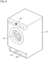
- FIG. 2 is a perspective view illustrating the laundry machine according to the present invention.
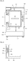
- FIG. 3 is a sectional view illustrating the laundry machine shown in FIG. 2 .
- the cabinet 110 which is included in the laundry machine 100 according to the present invention, includes a base 113 forming a bottom wall of the cabinet 110, side plates forming side walls of the cabinet 110, a rear cover forming a rear wall of the cabinet 110, and a front cover forming a front wall of the cabinet 110.
- a door 115 which is also included in the laundry machine 100, is mounted to the front cover.
- a control panel 170 is arranged on an upper portion of the front wall of the cabinet 110, to enable the user to operate the laundry machine 100.
- a tub 120 is arranged in the cabinet 110 in a state of being supported by a spring 101 and a damper 102.
- the damper 102 is connected to the tub 120 at an upper end of the damper 102, and is connected to one side wall or bottom wall of the cabinet 110 at a lower end of the damper 102.
- a bracket is provided at the side wall of the cabinet 110, to reinforce the strength of the side wall.
- a washing tub namely, a drum 130, which will receive laundry therein, is rotatably arranged in the tub 120.
- the drum 130 is rotated by a motor 140 fixedly mounted to a rear wall of the tub 120.
- a plurality of lifts 135 are arranged on an inner surface of the drum 130. The lifts 135 raise laundry received in the drum 130, and then let the raised laundry fall, to cause frictional force and impact force to be applied to the laundry.
- Water from an external water supply source is supplied to the tub 120 via a water supply hose 103, so that the supplied water is stored in the tub 120.
- the water stored in the tub 120 is outwardly discharged via a water discharge hose 104.
- a circulation hose 105 is also connected to the tub 120.
- a circulation pump 106 is arranged at an intermediate portion of the circulation hose 105. When the circulation pump 106 operates, the water stored in the tub 120 is discharged, and then again sprayed into the tub 120 via the circulation hose 105.
- As the water from the tub 120 is pumped, and is then again sprayed into the tub 120, a variety of water flows are generated in the drum 130, and an impact force and a frictional force are generated in accordance with the spray of water.
- a washing effect and a rinsing effect are enhanced.
- the washing tub of the laundry machine 100 namely, the drum 130, is vertically spaced apart from the installation surface of the laundry machine 100, to define a certain space to increase the level of the opening of the laundry machine 100, and thus to enable the user to easily load/unload laundry.
- the space corresponds to a space defined between a washing tub and a machine installation surface, for example, in a conventional laundry machine, in which a height increasing member is installed beneath the conventional laundry machine.
- the space between the washing tub, namely, the drum 130, and the installation surface is secured by a movable body 200, as shown in FIG. 3 .
- the washing tub, namely, the drum 130 must be arranged at a level increased by the height of the movable body 200, the level of the opening of the drum 130 is increased by the increased level of the drum 130.
- the user can load laundry into the drum 130 and can unload the laundry from the drum 130 upon using the laundry machine 100, without bending down too far.
- user convenience can be enhanced.
- the movable body 200 can be received in a space defined between the drum 130 and the base 113, and can be outwardly drawn from the cabinet 110. For these functions, an opening is formed through the front cover of the cabinet 110, in order to allow the movable body 200 to enter/exit the cabinet 110.
- a handle 210 may be provided at the movable body 200. Accordingly, the user can outwardly draw the movable body 200 from the cabinet 110 by grasping and pulling the handle 210, and can insert the movable body 200 into the space defined between the washing tub and the base 113 by grasping and pushing the handle 210.
- the movable body 200 may be implemented through various structures.
- a representative implementation example of the movable body 200 is a drawer. Where the movable body 200 comprises a drawer, there is a great convenience in that the user can store supplies for washing operations including a detergent, laundry, etc.
- the movable body 200 may comprise a small-size home appliance.
- a washing machine or a drying machine which has a small capacity, is implemented as the movable body 200
- the user may implement an arrangement in which one of the washing machine and drying machine is arranged at an upper position, and the other is arranged at a lower position such that the other machine is implemented as the movable body 200.
- a small-size home appliance which has a structure different from those of the above-described home appliances, and has a relation or no relation with washing operations, may be implemented as the movable body 200.
- a guide 270 which guides the movement of the movable body 200, is mounted to the cabinet 110.
- the guide 270 may have, for example, a rail structure, to smoothly guide a reciprocating movement of the movable body 200.
- FIGs. 4 to 9 illustrate examples for mounting the guide 270 to the cabinet 110.
- the guide 270 will be described in more detail with reference to these drawings.
- FIG. 6 illustrates an embodiment of the present invention.
- FIGs. 4 , 5 , 7 and 8 are included for illustrative purposes.
- the guide 270 is mounted on an inner surface of each side wall of the cabinet 110 at a lower portion of the side wall.
- the guide 270 has an elongated structure, for example, a rail structure.
- the guide 270 extends in a forward/rearward direction, namely, a longitudinal direction of the cabinet 110.
- a reinforcing member 260 may be attached to the side wall of the cabinet 110 at the lower portion of the side wall.
- a structure corresponding to the guide 270 is provided at the movable body 200.
- a bracket 201 is attached to a side surface of the movable body 200 facing the guide 270 at a position corresponding to the guide 270.
- a roller 203 may be provided at the bracket 201 such that the roller 203 rolls along the guide 270.
- the movable body 200 can be smoothly reciprocated by the guide 270 and roller 203.
- the guide 270 is mounted on the base 113, which forms the bottom wall of the cabinet 110, at either side of the base 113. If necessary, a reinforcing member 260 may be attached to the base 113, in order to reinforce the strength of the base 113.
- a structure corresponding to the guide 270 is provided at the bottom wall of the movable body 200.
- a bracket 201 is attached to the bottom wall of the movable body 200 at a position corresponding to the guide 270.
- a roller 203 may be provided at the bracket 201 such that the roller 203 rolls along the guide 270.
- the movable body 200 can be smoothly reciprocated by the guide 270 and roller 203.
- the guide 270 is firmly fitted between a lower end of each side wall of the cabinet 110 and the base 113.
- a flange 111 is formed at the lower end of the side wall of the cabinet 110 so that the flange 111 can be coupled with the base 113.
- One end of the guide 270 is firmly fitted between the lateral end of the base 113, which corresponds to the side wall of the cabinet 110, and the flange 111.
- the guide 270 is fixed by fastening members to fasten the cabinet 110 and base 113 to each other. Accordingly, it is unnecessary to separately fasten the guide 270 to the cabinet 110.
- the guide 270 is arranged on the base 113.
- a structure corresponding to the guide 270 for example, a bracket 201 and a roller 203, is provided at the bottom wall of the movable body 200.
- the movable body 200 can be smoothly moved by the guide 270 and roller 203.
- the guide 270 may be arranged in parallel to the side wall of the cabinet 110, without being arranged on the base 113.
- the guide 270 is firmly fitted between the flange 111 of the cabinet 110 and the base 113 at one end of the guide 270.
- An intermediate portion of the guide 270 is substantially vertically bent from the end of the guide 270 such that the intermediate portion is in close contact with the lower end of the side wall of the cabinet 110 or is arranged in parallel with the lower end of the side wall of the cabinet 110.
- the guide 270 which is mounted to the cabinet 110, as described above, smoothly guides the reciprocation of the movable body 200. If necessary, a reinforcing member 260 is interposed between the cabinet 110 and the guide 270, to reinforce the strength of a region where the guide 270 is mounted, namely, the lower end of the side wall of the cabinet 110 or the base 113. Also, the guide 270 may be firmly fitted between connecting portions of the side wall of the cabinet 110 and base 113.
- a guide 112 is protruded from an upper surface of the base 113.
- the guide 112 has an elongated rail structure.
- the guide 112 extends in a forward/rearward direction of the laundry machine 100, to guide a reciprocation of the movable body 200.
- a structure corresponding to the guide 112 is provided at the movable body 200.
- a bracket 201 is attached to the bottom wall of the movable body 200 at a position corresponding to the guide 112.
- a roller 203 may be provided at the bracket 201 such that the roller 203 rolls along the guide 112.
- the movable body 200 can be smoothly reciprocated by the guide 112 and roller 203.
- a guide 114 is formed at an upper surface of the base 113, in the form of a groove.
- the groove is elongated along a forward/rearward direction of the laundry machine 100.
- a structure corresponding to the guide 114 is provided at the bottom wall of the movable body 200.
- a bracket 201 is attached to the bottom wall of the movable body 200 at a position corresponding to the guide 114.
- a roller 203 may be provided at the bracket 201 such that the roller 203 rolls along the guide 114.
- the movable body 200 can be smoothly reciprocated.
- a protrusion may be provided, in place of the roller 203, at the bottom wall of the movable body 200 such that the protrusion is engaged in the groove-shaped guide 114.
- a stopper 116 may be provided at an end of the guide 114, to limit the outward movement length of the movable body 200.
- the stopper 116 extends upwardly from the bottom of the guide 114 at an end of the guide 114, to limit the rolling of the roller 203, and thus to prevent the movable body 200 from being outwardly drawn beyond a position corresponding to the stopper 116.
- an upwardly-protruded stopper may be provided at an end of the guide 112 in the case of FIG. 7 .
Landscapes
- Engineering & Computer Science (AREA)
- Textile Engineering (AREA)
- Main Body Construction Of Washing Machines And Laundry Dryers (AREA)
- Accessory Of Washing/Drying Machine, Commercial Washing/Drying Machine, Other Washing/Drying Machine (AREA)
Claims (9)
- Machine à laver le linge comprenant :une carrosserie (110) comprenant une base (113) formant un fond, des plaques latérales formant des parois latérales, un couvercle arrière formant une paroi arrière, un couvercle avant formant une paroi avant, et une ouverture prévue dans le couvercle avant ;une cuve de lavage (120) agencée dans la carrosserie (110) pour recevoir du linge ;un corps mobile (200) agencé dans la carrosserie (110) et installé entre la cuve de lavage (120) et la base (113), le corps mobile (200) étant mobile vers l'extérieur hors de la carrosserie (110) à travers l'ouverture ;une monture (201) prévue sur le corps mobile (200) ;un guide (270) prévu sur la carrosserie (110) pour guider un mouvement de la monture (201) ;une bride (111) formée à l'extrémité inférieure des plaques latérales,caractérisé en ce qu'une extrémité du guide (270) est logée entre la bride (111) et la base (113), et le guide (270) est fixé par des éléments de fixation pour fixer la bride (111) et la base (113) l'une à l'autre.
- Machine à laver le linge selon la revendication 1, dans laquelle la monture (201) est prévue dans un fond du corps mobile (200), et le guide (270) est prévue dans la base (113) en face du fond du corps mobile (200).
- Machine à laver le linge selon la revendication 1, dans laquelle le guide (270) est prévu dans les plaques latérales, et la monture (201) est prévue dans une paroi latérale du corps mobile (200) qui fait face vers les plaques latérales.
- Machine à laver le linge selon la revendication 2, comprenant un élément de renfort de solidité (260) agencé entre le guide (270) et la base (113).
- Machine à laver le linge selon la revendication 3, comprenant en outre un élément de renfort de solidité (260) prévu dans un espace entre le guide (270) et les plaques latérales.
- Machine à laver le linge selon la revendication 1, dans laquelle le guide (270) est pourvu d'un arrêt (116) formé à une extrémité du guide (270) pour limiter une longueur du mouvement vers l'extérieur du corps mobile (200).
- Machine à laver le linge selon la revendication 1, comprenant en outre une roulette (203) agencée entre le guide (270) et la monture (201).
- Machine à laver le linge selon la revendication 1, comprenant en outre :un amortisseur (102) pour supporter la cuve de lavage (120) ; etun support d'amortisseur pour supporter l'amortisseur (102) tout en empêchant que l'amortisseur interfère avec le mouvement du corps mobile (200).
- Machine à laver le linge selon la revendication 8, dans laquelle au moins une portion du support d'amortisseur est agencée entre les plaques latérales et un espace dans lequel le corps mobile (200) est reçu.
Applications Claiming Priority (3)
| Application Number | Priority Date | Filing Date | Title |
|---|---|---|---|
| KR1020070048097A KR101443607B1 (ko) | 2007-05-17 | 2007-05-17 | 세탁물 처리 장치 |
| KR1020070048096A KR101467749B1 (ko) | 2007-05-17 | 2007-05-17 | 세탁물 처리 장치 |
| PCT/KR2008/002751 WO2008143436A2 (fr) | 2007-05-17 | 2008-05-16 | Machine pour la lessive |
Publications (3)
| Publication Number | Publication Date |
|---|---|
| EP2155948A2 EP2155948A2 (fr) | 2010-02-24 |
| EP2155948A4 EP2155948A4 (fr) | 2014-06-04 |
| EP2155948B1 true EP2155948B1 (fr) | 2018-04-18 |
Family
ID=40032278
Family Applications (1)
| Application Number | Title | Priority Date | Filing Date |
|---|---|---|---|
| EP08753547.2A Active EP2155948B1 (fr) | 2007-05-17 | 2008-05-16 | Machine pour la lessive |
Country Status (4)
| Country | Link |
|---|---|
| US (1) | US20090013730A1 (fr) |
| EP (1) | EP2155948B1 (fr) |
| CN (1) | CN101970745B (fr) |
| WO (1) | WO2008143436A2 (fr) |
Families Citing this family (9)
| Publication number | Priority date | Publication date | Assignee | Title |
|---|---|---|---|---|
| KR101542389B1 (ko) * | 2009-02-05 | 2015-08-06 | 엘지전자 주식회사 | 히트펌프모듈 및 히트펌프모듈을 이용한 건조장치 |
| US8490438B2 (en) | 2009-02-05 | 2013-07-23 | Lg Electronics Inc. | Laundry treatment device |
| WO2010095833A2 (fr) * | 2009-02-23 | 2010-08-26 | Lg Electronics Inc. | Lave-linge |
| KR101603106B1 (ko) * | 2009-03-03 | 2016-03-14 | 엘지전자 주식회사 | 세탁 장치 |
| KR101742991B1 (ko) | 2009-05-11 | 2017-06-02 | 엘지전자 주식회사 | 세탁장치 |
| WO2011136609A2 (fr) * | 2010-04-30 | 2011-11-03 | Lg Electronics Inc. | Machine à laver le linge |
| US20110294913A1 (en) | 2010-05-17 | 2011-12-01 | Michael Zimmer | Flexible material for surface adhesive rule |
| US20130219972A1 (en) * | 2012-02-27 | 2013-08-29 | General Electric Company | Washing machine appliance with an accessible reservoir |
| WO2024055873A1 (fr) * | 2022-09-15 | 2024-03-21 | 青岛海尔洗衣机有限公司 | Appareil de traitement de vêtements |
Citations (5)
| Publication number | Priority date | Publication date | Assignee | Title |
|---|---|---|---|---|
| US6010200A (en) * | 1998-09-25 | 2000-01-04 | R&R Technologies, Llc | Adapter rail for plastic drawer |
| US6217139B1 (en) * | 1997-09-09 | 2001-04-17 | Kimball International, Inc. | Drawer for standardized furniture unit |
| US6659576B1 (en) * | 2000-05-12 | 2003-12-09 | Herb Welch | Method and device for mounting a modular drawer and support inside a cabinet |
| US20050275325A1 (en) * | 2004-06-14 | 2005-12-15 | Samsung Electronics Co., Ltd | Supporter for clothes washing machine and clothes drying apparatus |
| JP2006029618A (ja) * | 2004-07-13 | 2006-02-02 | Matsushita Electric Ind Co Ltd | 冷蔵庫 |
Family Cites Families (28)
| Publication number | Priority date | Publication date | Assignee | Title |
|---|---|---|---|---|
| DE1135408B (de) * | 1958-03-03 | 1962-08-30 | Lazare Lespinasse | Waschmaschinenaufbau |
| US4002199A (en) * | 1975-11-10 | 1977-01-11 | General Motors Corporation | Refrigerator food conditioning appliance |
| US4618193A (en) * | 1983-12-07 | 1986-10-21 | Whirlpool Corporation | Cabinet construction for an automatic washer |
| SE9001336L (sv) * | 1990-04-12 | 1991-10-13 | Electrolux Ab | Anordning vid en diskmaskin |
| JP3012798B2 (ja) * | 1994-12-20 | 2000-02-28 | 萬都機械株式会社 | キムチ貯蔵庫 |
| US6158257A (en) * | 1995-01-23 | 2000-12-12 | General Electric Company | Horizontal axis clothes washing machine with balance rings |
| CN2256089Y (zh) * | 1995-12-23 | 1997-06-11 | 安徽博西扬家用冷柜有限公司 | 冰箱用滚轮式抽屉 |
| US5829767A (en) * | 1996-03-07 | 1998-11-03 | Grossman; Glenn D. | Knock-down cart |
| US7617702B2 (en) * | 2000-07-25 | 2009-11-17 | Whirlpool Corporation | Modular laundry system with cabinet module |
| US7628043B2 (en) * | 2000-07-25 | 2009-12-08 | Whirlpool Corporation | Modular laundry system with horizontal modules |
| US20020017117A1 (en) * | 2000-07-25 | 2002-02-14 | Sunshine Richard A. | Integrated laundry center |
| US7624600B2 (en) * | 2000-07-25 | 2009-12-01 | Whirlpool Corporation | Modular laundry system with horizontally arranged cabinet module |
| AU760902B2 (en) * | 2000-10-12 | 2003-05-22 | Lg Electronics Inc. | Drawer-type washing machine |
| NZ512503A (en) * | 2000-11-13 | 2002-11-26 | Lg Electronics Inc | Drawer-type washing machine and locking method thereof |
| DE60117953T2 (de) * | 2001-01-26 | 2006-11-30 | Candy S.P.A., Monza | Haushaltswaschmaschine mit zwei abgeteilten Räumen |
| CA2344923A1 (fr) * | 2001-04-20 | 2002-10-20 | Camco Inc. | Tiroir de fermeture de meuble de refrigerateur renforce |
| DE20302572U1 (de) * | 2003-02-18 | 2003-04-24 | Hansen, Nikolaus, 77880 Sasbach | Unterschrank für Waschmaschinen mit einer ausziehbaren und abschließbaren Schublade zum Aufbewahren von Waschmittel |
| ITTO20030236A1 (it) * | 2003-03-28 | 2004-09-29 | Merloni Elettrodomestici Spa | Macchina lavabiancheria, in particolare a caricamento |
| US7640612B2 (en) * | 2004-01-09 | 2010-01-05 | Schock Metallwerk Gmbh | Device incorporating a chamber through which fluid is adapted to flow and the use of a drawer guide in such a device |
| KR101010689B1 (ko) * | 2004-02-06 | 2011-01-24 | 엘지전자 주식회사 | 세탁기용 받침대 |
| US7313933B2 (en) * | 2004-02-18 | 2008-01-01 | Whirlpool Corporation | Laundry appliance utility shelf |
| CN1667177A (zh) * | 2004-03-09 | 2005-09-14 | 三洋电机株式会社 | 干燥机 |
| EP1681525A3 (fr) * | 2004-12-22 | 2006-08-30 | Samsung Electronics Co., Ltd. | Réfrigérateur et procédé de fabrication d'un réfrigérateur |
| EP1849905B1 (fr) * | 2005-02-02 | 2008-11-19 | Girbau, S.A. | Structure support pour machine a laver le linge |
| US7802855B2 (en) * | 2005-09-30 | 2010-09-28 | General Electric Company | Home appliance having a door |
| DE102005053554B3 (de) * | 2005-11-08 | 2006-10-26 | Miele & Cie. Kg | Sockelgestell für eine Wäschebehandlungsmaschine |
| DE102006019608A1 (de) * | 2006-04-25 | 2007-11-08 | Miele & Cie. Kg | System, bestehend aus Haushaltgerät mit Sockel bzw. Unterbausatz |
| EP2063012B1 (fr) * | 2007-11-21 | 2013-09-18 | LG Electronics Inc. | Machine à laver |
-
2008
- 2008-05-16 US US12/122,245 patent/US20090013730A1/en not_active Abandoned
- 2008-05-16 WO PCT/KR2008/002751 patent/WO2008143436A2/fr active Application Filing
- 2008-05-16 CN CN2008800249341A patent/CN101970745B/zh not_active Expired - Fee Related
- 2008-05-16 EP EP08753547.2A patent/EP2155948B1/fr active Active
Patent Citations (5)
| Publication number | Priority date | Publication date | Assignee | Title |
|---|---|---|---|---|
| US6217139B1 (en) * | 1997-09-09 | 2001-04-17 | Kimball International, Inc. | Drawer for standardized furniture unit |
| US6010200A (en) * | 1998-09-25 | 2000-01-04 | R&R Technologies, Llc | Adapter rail for plastic drawer |
| US6659576B1 (en) * | 2000-05-12 | 2003-12-09 | Herb Welch | Method and device for mounting a modular drawer and support inside a cabinet |
| US20050275325A1 (en) * | 2004-06-14 | 2005-12-15 | Samsung Electronics Co., Ltd | Supporter for clothes washing machine and clothes drying apparatus |
| JP2006029618A (ja) * | 2004-07-13 | 2006-02-02 | Matsushita Electric Ind Co Ltd | 冷蔵庫 |
Also Published As
| Publication number | Publication date |
|---|---|
| CN101970745A (zh) | 2011-02-09 |
| EP2155948A2 (fr) | 2010-02-24 |
| EP2155948A4 (fr) | 2014-06-04 |
| US20090013730A1 (en) | 2009-01-15 |
| CN101970745B (zh) | 2012-12-12 |
| WO2008143436A3 (fr) | 2010-10-07 |
| WO2008143436A2 (fr) | 2008-11-27 |
Similar Documents
| Publication | Publication Date | Title |
|---|---|---|
| EP2155948B1 (fr) | Machine pour la lessive | |
| CA2707879C (fr) | Machine a laver | |
| EP2152951B1 (fr) | Machine pour la lessive | |
| EP2189566B1 (fr) | Machine de traitement du linge | |
| US9267228B2 (en) | Laundry treating device | |
| US12035869B2 (en) | Dishwasher | |
| KR101443607B1 (ko) | 세탁물 처리 장치 | |
| KR101467749B1 (ko) | 세탁물 처리 장치 | |
| KR101443606B1 (ko) | 세탁물 처리장치 | |
| KR101396970B1 (ko) | 세탁물 처리 장치와 세탁물 처리 장치용 키높이 부재 | |
| CN214422941U (zh) | 一种用于家用电器的底座和家用电器 | |
| KR101387483B1 (ko) | 세탁물 처리 장치 및 세탁물 처리 장치를 위한 장식용프론트 커버 | |
| KR101435793B1 (ko) | 세탁물 처리장치 | |
| KR101422004B1 (ko) | 세탁물 처리장치 | |
| KR101526964B1 (ko) | 세탁물 처리장치 | |
| KR20080101375A (ko) | 세탁물 처리장치 | |
| KR101356498B1 (ko) | 세탁물 처리장치 | |
| KR20080101381A (ko) | 세탁물 처리장치 | |
| EP1598472A1 (fr) | Machine à laver | |
| EP2065507B1 (fr) | Machine de blanchisserie | |
| KR20230172811A (ko) | 의류처리장치 | |
| KR20230172810A (ko) | 의류처리장치 | |
| KR101443608B1 (ko) | 세탁물 처리 장치 |
Legal Events
| Date | Code | Title | Description |
|---|---|---|---|
| PUAI | Public reference made under article 153(3) epc to a published international application that has entered the european phase |
Free format text: ORIGINAL CODE: 0009012 |
|
| 17P | Request for examination filed |
Effective date: 20091202 |
|
| AK | Designated contracting states |
Kind code of ref document: A2 Designated state(s): AT BE BG CH CY CZ DE DK EE ES FI FR GB GR HR HU IE IS IT LI LT LU LV MC MT NL NO PL PT RO SE SI SK TR |
|
| AX | Request for extension of the european patent |
Extension state: AL BA MK RS |
|
| R17D | Deferred search report published (corrected) |
Effective date: 20101007 |
|
| DAX | Request for extension of the european patent (deleted) | ||
| A4 | Supplementary search report drawn up and despatched |
Effective date: 20140508 |
|
| RIC1 | Information provided on ipc code assigned before grant |
Ipc: D06F 39/12 20060101AFI20140430BHEP Ipc: D06F 29/00 20060101ALI20140430BHEP |
|
| 17Q | First examination report despatched |
Effective date: 20161024 |
|
| GRAP | Despatch of communication of intention to grant a patent |
Free format text: ORIGINAL CODE: EPIDOSNIGR1 |
|
| INTG | Intention to grant announced |
Effective date: 20171025 |
|
| RAP1 | Party data changed (applicant data changed or rights of an application transferred) |
Owner name: LG ELECTRONICS INC. |
|
| GRAJ | Information related to disapproval of communication of intention to grant by the applicant or resumption of examination proceedings by the epo deleted |
Free format text: ORIGINAL CODE: EPIDOSDIGR1 |
|
| GRAR | Information related to intention to grant a patent recorded |
Free format text: ORIGINAL CODE: EPIDOSNIGR71 |
|
| GRAS | Grant fee paid |
Free format text: ORIGINAL CODE: EPIDOSNIGR3 |
|
| GRAA | (expected) grant |
Free format text: ORIGINAL CODE: 0009210 |
|
| INTC | Intention to grant announced (deleted) | ||
| AK | Designated contracting states |
Kind code of ref document: B1 Designated state(s): AT BE BG CH CY CZ DE DK EE ES FI FR GB GR HR HU IE IS IT LI LT LU LV MC MT NL NO PL PT RO SE SI SK TR |
|
| INTG | Intention to grant announced |
Effective date: 20180313 |
|
| REG | Reference to a national code |
Ref country code: GB Ref legal event code: FG4D |
|
| REG | Reference to a national code |
Ref country code: CH Ref legal event code: EP |
|
| REG | Reference to a national code |
Ref country code: AT Ref legal event code: REF Ref document number: 990603 Country of ref document: AT Kind code of ref document: T Effective date: 20180515 |
|
| REG | Reference to a national code |
Ref country code: IE Ref legal event code: FG4D |
|
| REG | Reference to a national code |
Ref country code: DE Ref legal event code: R096 Ref document number: 602008054891 Country of ref document: DE |
|
| REG | Reference to a national code |
Ref country code: FR Ref legal event code: PLFP Year of fee payment: 11 |
|
| REG | Reference to a national code |
Ref country code: NL Ref legal event code: MP Effective date: 20180418 |
|
| REG | Reference to a national code |
Ref country code: LT Ref legal event code: MG4D |
|
| PG25 | Lapsed in a contracting state [announced via postgrant information from national office to epo] |
Ref country code: NL Free format text: LAPSE BECAUSE OF FAILURE TO SUBMIT A TRANSLATION OF THE DESCRIPTION OR TO PAY THE FEE WITHIN THE PRESCRIBED TIME-LIMIT Effective date: 20180418 |
|
| PG25 | Lapsed in a contracting state [announced via postgrant information from national office to epo] |
Ref country code: PL Free format text: LAPSE BECAUSE OF FAILURE TO SUBMIT A TRANSLATION OF THE DESCRIPTION OR TO PAY THE FEE WITHIN THE PRESCRIBED TIME-LIMIT Effective date: 20180418 Ref country code: NO Free format text: LAPSE BECAUSE OF FAILURE TO SUBMIT A TRANSLATION OF THE DESCRIPTION OR TO PAY THE FEE WITHIN THE PRESCRIBED TIME-LIMIT Effective date: 20180718 Ref country code: FI Free format text: LAPSE BECAUSE OF FAILURE TO SUBMIT A TRANSLATION OF THE DESCRIPTION OR TO PAY THE FEE WITHIN THE PRESCRIBED TIME-LIMIT Effective date: 20180418 Ref country code: SE Free format text: LAPSE BECAUSE OF FAILURE TO SUBMIT A TRANSLATION OF THE DESCRIPTION OR TO PAY THE FEE WITHIN THE PRESCRIBED TIME-LIMIT Effective date: 20180418 Ref country code: BG Free format text: LAPSE BECAUSE OF FAILURE TO SUBMIT A TRANSLATION OF THE DESCRIPTION OR TO PAY THE FEE WITHIN THE PRESCRIBED TIME-LIMIT Effective date: 20180718 Ref country code: ES Free format text: LAPSE BECAUSE OF FAILURE TO SUBMIT A TRANSLATION OF THE DESCRIPTION OR TO PAY THE FEE WITHIN THE PRESCRIBED TIME-LIMIT Effective date: 20180418 Ref country code: LT Free format text: LAPSE BECAUSE OF FAILURE TO SUBMIT A TRANSLATION OF THE DESCRIPTION OR TO PAY THE FEE WITHIN THE PRESCRIBED TIME-LIMIT Effective date: 20180418 |
|
| PG25 | Lapsed in a contracting state [announced via postgrant information from national office to epo] |
Ref country code: HR Free format text: LAPSE BECAUSE OF FAILURE TO SUBMIT A TRANSLATION OF THE DESCRIPTION OR TO PAY THE FEE WITHIN THE PRESCRIBED TIME-LIMIT Effective date: 20180418 Ref country code: GR Free format text: LAPSE BECAUSE OF FAILURE TO SUBMIT A TRANSLATION OF THE DESCRIPTION OR TO PAY THE FEE WITHIN THE PRESCRIBED TIME-LIMIT Effective date: 20180719 Ref country code: LV Free format text: LAPSE BECAUSE OF FAILURE TO SUBMIT A TRANSLATION OF THE DESCRIPTION OR TO PAY THE FEE WITHIN THE PRESCRIBED TIME-LIMIT Effective date: 20180418 |
|
| REG | Reference to a national code |
Ref country code: CH Ref legal event code: PL |
|
| REG | Reference to a national code |
Ref country code: AT Ref legal event code: MK05 Ref document number: 990603 Country of ref document: AT Kind code of ref document: T Effective date: 20180418 |
|
| PG25 | Lapsed in a contracting state [announced via postgrant information from national office to epo] |
Ref country code: PT Free format text: LAPSE BECAUSE OF FAILURE TO SUBMIT A TRANSLATION OF THE DESCRIPTION OR TO PAY THE FEE WITHIN THE PRESCRIBED TIME-LIMIT Effective date: 20180820 |
|
| REG | Reference to a national code |
Ref country code: DE Ref legal event code: R097 Ref document number: 602008054891 Country of ref document: DE |
|
| REG | Reference to a national code |
Ref country code: BE Ref legal event code: MM Effective date: 20180531 |
|
| PG25 | Lapsed in a contracting state [announced via postgrant information from national office to epo] |
Ref country code: MC Free format text: LAPSE BECAUSE OF FAILURE TO SUBMIT A TRANSLATION OF THE DESCRIPTION OR TO PAY THE FEE WITHIN THE PRESCRIBED TIME-LIMIT Effective date: 20180418 Ref country code: DK Free format text: LAPSE BECAUSE OF FAILURE TO SUBMIT A TRANSLATION OF THE DESCRIPTION OR TO PAY THE FEE WITHIN THE PRESCRIBED TIME-LIMIT Effective date: 20180418 Ref country code: CZ Free format text: LAPSE BECAUSE OF FAILURE TO SUBMIT A TRANSLATION OF THE DESCRIPTION OR TO PAY THE FEE WITHIN THE PRESCRIBED TIME-LIMIT Effective date: 20180418 Ref country code: RO Free format text: LAPSE BECAUSE OF FAILURE TO SUBMIT A TRANSLATION OF THE DESCRIPTION OR TO PAY THE FEE WITHIN THE PRESCRIBED TIME-LIMIT Effective date: 20180418 Ref country code: EE Free format text: LAPSE BECAUSE OF FAILURE TO SUBMIT A TRANSLATION OF THE DESCRIPTION OR TO PAY THE FEE WITHIN THE PRESCRIBED TIME-LIMIT Effective date: 20180418 Ref country code: AT Free format text: LAPSE BECAUSE OF FAILURE TO SUBMIT A TRANSLATION OF THE DESCRIPTION OR TO PAY THE FEE WITHIN THE PRESCRIBED TIME-LIMIT Effective date: 20180418 Ref country code: SK Free format text: LAPSE BECAUSE OF FAILURE TO SUBMIT A TRANSLATION OF THE DESCRIPTION OR TO PAY THE FEE WITHIN THE PRESCRIBED TIME-LIMIT Effective date: 20180418 |
|
| REG | Reference to a national code |
Ref country code: IE Ref legal event code: MM4A |
|
| PLBE | No opposition filed within time limit |
Free format text: ORIGINAL CODE: 0009261 |
|
| STAA | Information on the status of an ep patent application or granted ep patent |
Free format text: STATUS: NO OPPOSITION FILED WITHIN TIME LIMIT |
|
| PG25 | Lapsed in a contracting state [announced via postgrant information from national office to epo] |
Ref country code: IT Free format text: LAPSE BECAUSE OF FAILURE TO SUBMIT A TRANSLATION OF THE DESCRIPTION OR TO PAY THE FEE WITHIN THE PRESCRIBED TIME-LIMIT Effective date: 20180418 Ref country code: LI Free format text: LAPSE BECAUSE OF NON-PAYMENT OF DUE FEES Effective date: 20180531 Ref country code: CH Free format text: LAPSE BECAUSE OF NON-PAYMENT OF DUE FEES Effective date: 20180531 |
|
| 26N | No opposition filed |
Effective date: 20190121 |
|
| PG25 | Lapsed in a contracting state [announced via postgrant information from national office to epo] |
Ref country code: LU Free format text: LAPSE BECAUSE OF NON-PAYMENT OF DUE FEES Effective date: 20180516 |
|
| PG25 | Lapsed in a contracting state [announced via postgrant information from national office to epo] |
Ref country code: IE Free format text: LAPSE BECAUSE OF NON-PAYMENT OF DUE FEES Effective date: 20180516 |
|
| PG25 | Lapsed in a contracting state [announced via postgrant information from national office to epo] |
Ref country code: SI Free format text: LAPSE BECAUSE OF FAILURE TO SUBMIT A TRANSLATION OF THE DESCRIPTION OR TO PAY THE FEE WITHIN THE PRESCRIBED TIME-LIMIT Effective date: 20180418 Ref country code: BE Free format text: LAPSE BECAUSE OF NON-PAYMENT OF DUE FEES Effective date: 20180531 |
|
| PG25 | Lapsed in a contracting state [announced via postgrant information from national office to epo] |
Ref country code: MT Free format text: LAPSE BECAUSE OF NON-PAYMENT OF DUE FEES Effective date: 20180516 |
|
| PG25 | Lapsed in a contracting state [announced via postgrant information from national office to epo] |
Ref country code: TR Free format text: LAPSE BECAUSE OF FAILURE TO SUBMIT A TRANSLATION OF THE DESCRIPTION OR TO PAY THE FEE WITHIN THE PRESCRIBED TIME-LIMIT Effective date: 20180418 |
|
| PG25 | Lapsed in a contracting state [announced via postgrant information from national office to epo] |
Ref country code: HU Free format text: LAPSE BECAUSE OF FAILURE TO SUBMIT A TRANSLATION OF THE DESCRIPTION OR TO PAY THE FEE WITHIN THE PRESCRIBED TIME-LIMIT; INVALID AB INITIO Effective date: 20080516 |
|
| PG25 | Lapsed in a contracting state [announced via postgrant information from national office to epo] |
Ref country code: CY Free format text: LAPSE BECAUSE OF FAILURE TO SUBMIT A TRANSLATION OF THE DESCRIPTION OR TO PAY THE FEE WITHIN THE PRESCRIBED TIME-LIMIT Effective date: 20180418 |
|
| PG25 | Lapsed in a contracting state [announced via postgrant information from national office to epo] |
Ref country code: IS Free format text: LAPSE BECAUSE OF FAILURE TO SUBMIT A TRANSLATION OF THE DESCRIPTION OR TO PAY THE FEE WITHIN THE PRESCRIBED TIME-LIMIT Effective date: 20180818 |
|
| PGFP | Annual fee paid to national office [announced via postgrant information from national office to epo] |
Ref country code: GB Payment date: 20220405 Year of fee payment: 15 Ref country code: FR Payment date: 20220413 Year of fee payment: 15 |
|
| GBPC | Gb: european patent ceased through non-payment of renewal fee |
Effective date: 20230516 |
|
| PG25 | Lapsed in a contracting state [announced via postgrant information from national office to epo] |
Ref country code: GB Free format text: LAPSE BECAUSE OF NON-PAYMENT OF DUE FEES Effective date: 20230516 |
|
| PG25 | Lapsed in a contracting state [announced via postgrant information from national office to epo] |
Ref country code: FR Free format text: LAPSE BECAUSE OF NON-PAYMENT OF DUE FEES Effective date: 20230531 |
|
| PGFP | Annual fee paid to national office [announced via postgrant information from national office to epo] |
Ref country code: DE Payment date: 20240405 Year of fee payment: 17 |