EP2155286B1 - Gerät und verfahren zur auftrennung einer zusammengesetzten flüssigkeit in wenigstens zwei komponenten - Google Patents
Gerät und verfahren zur auftrennung einer zusammengesetzten flüssigkeit in wenigstens zwei komponenten Download PDFInfo
- Publication number
- EP2155286B1 EP2155286B1 EP07863724.6A EP07863724A EP2155286B1 EP 2155286 B1 EP2155286 B1 EP 2155286B1 EP 07863724 A EP07863724 A EP 07863724A EP 2155286 B1 EP2155286 B1 EP 2155286B1
- Authority
- EP
- European Patent Office
- Prior art keywords
- bag
- component
- transfer
- separation
- separation bag
- Prior art date
- Legal status (The legal status is an assumption and is not a legal conclusion. Google has not performed a legal analysis and makes no representation as to the accuracy of the status listed.)
- Active
Links
Images

Classifications
-
- A—HUMAN NECESSITIES
- A61—MEDICAL OR VETERINARY SCIENCE; HYGIENE
- A61M—DEVICES FOR INTRODUCING MEDIA INTO, OR ONTO, THE BODY; DEVICES FOR TRANSDUCING BODY MEDIA OR FOR TAKING MEDIA FROM THE BODY; DEVICES FOR PRODUCING OR ENDING SLEEP OR STUPOR
- A61M1/00—Suction or pumping devices for medical purposes; Devices for carrying-off, for treatment of, or for carrying-over, body-liquids; Drainage systems
- A61M1/36—Other treatment of blood in a by-pass of the natural circulatory system, e.g. temperature adaptation, irradiation ; Extra-corporeal blood circuits
- A61M1/3693—Other treatment of blood in a by-pass of the natural circulatory system, e.g. temperature adaptation, irradiation ; Extra-corporeal blood circuits using separation based on different densities of components, e.g. centrifuging
-
- A—HUMAN NECESSITIES
- A61—MEDICAL OR VETERINARY SCIENCE; HYGIENE
- A61M—DEVICES FOR INTRODUCING MEDIA INTO, OR ONTO, THE BODY; DEVICES FOR TRANSDUCING BODY MEDIA OR FOR TAKING MEDIA FROM THE BODY; DEVICES FOR PRODUCING OR ENDING SLEEP OR STUPOR
- A61M1/00—Suction or pumping devices for medical purposes; Devices for carrying-off, for treatment of, or for carrying-over, body-liquids; Drainage systems
- A61M1/02—Blood transfusion apparatus
- A61M1/0209—Multiple bag systems for separating or storing blood components
-
- A—HUMAN NECESSITIES
- A61—MEDICAL OR VETERINARY SCIENCE; HYGIENE
- A61M—DEVICES FOR INTRODUCING MEDIA INTO, OR ONTO, THE BODY; DEVICES FOR TRANSDUCING BODY MEDIA OR FOR TAKING MEDIA FROM THE BODY; DEVICES FOR PRODUCING OR ENDING SLEEP OR STUPOR
- A61M1/00—Suction or pumping devices for medical purposes; Devices for carrying-off, for treatment of, or for carrying-over, body-liquids; Drainage systems
- A61M1/36—Other treatment of blood in a by-pass of the natural circulatory system, e.g. temperature adaptation, irradiation ; Extra-corporeal blood circuits
- A61M1/3693—Other treatment of blood in a by-pass of the natural circulatory system, e.g. temperature adaptation, irradiation ; Extra-corporeal blood circuits using separation based on different densities of components, e.g. centrifuging
- A61M1/3696—Other treatment of blood in a by-pass of the natural circulatory system, e.g. temperature adaptation, irradiation ; Extra-corporeal blood circuits using separation based on different densities of components, e.g. centrifuging with means for adding or withdrawing liquid substances during the centrifugation, e.g. continuous centrifugation
-
- A—HUMAN NECESSITIES
- A61—MEDICAL OR VETERINARY SCIENCE; HYGIENE
- A61M—DEVICES FOR INTRODUCING MEDIA INTO, OR ONTO, THE BODY; DEVICES FOR TRANSDUCING BODY MEDIA OR FOR TAKING MEDIA FROM THE BODY; DEVICES FOR PRODUCING OR ENDING SLEEP OR STUPOR
- A61M1/00—Suction or pumping devices for medical purposes; Devices for carrying-off, for treatment of, or for carrying-over, body-liquids; Drainage systems
- A61M1/36—Other treatment of blood in a by-pass of the natural circulatory system, e.g. temperature adaptation, irradiation ; Extra-corporeal blood circuits
- A61M1/3693—Other treatment of blood in a by-pass of the natural circulatory system, e.g. temperature adaptation, irradiation ; Extra-corporeal blood circuits using separation based on different densities of components, e.g. centrifuging
- A61M1/3698—Expressing processed fluid out from the turning rotor using another fluid compressing the treatment chamber; Variable volume rotors
Definitions
- the present invention concerns an apparatus and a method for separating a volume of composite liquid or blood product into at least two components.
- the apparatus and method of the invention are particularly appropriate for the separation of biological fluids comprising an aqueous component and one or more cellular components.
- potential uses of the invention include extracting, from a volume of whole blood, a plasma component, a first cellular component including platelets, a second cellular component including mononuclear cells, and a third cellular component including red blood cells and granulocytes.
- European patent application EP 1 566 191 describes a method and an apparatus for separating a volume of whole blood into at least two components in accordance with various separation protocols.
- one protocol provides for the separation of a volume of whole blood into a plasma component, a platelet component, and a red blood cell component.
- the apparatus comprises a centrifuge adapted to cooperate with various bag sets, in particular a bag set comprising an annular separation bag for whole blood, which is connected to a platelet component bag, a plasma component bag, and a red blood cell component bag.
- the centrifuge includes:
- WO 2006/071496 A2 discloses apparatus and method for centrifugal separation of blood into four layers or components.
- the apparatus further includes a squeezing system, at least one sensor, and a control unit for receiving information from the sensor.
- US 2006/0205581 A1 discloses a blood processing centrifuge for processing whole blood wherein the separated buffy coat may be displaced in a series of intermittent spurts.
- the invention provides a method of separating a composite liquid into at least a first component and a second component, comprising centrifuging a separation bag containing a volume of composite liquid so as to cause the sedimentation of at least a first component and a second component; squeezing the separation bag to transfer some of the second component to a first transfer line attached to a first transfer bag and the separation bag; stopping the transfer of the second component to the first transfer line; squeezing the separation bag after the stopping step to build up an over-pressure in the separation bag; and transferring, using the over-pressure, a part of the second component remaining in the separation bag to the transfer bag through the first transfer line wherein the over-pressure causes the second component to rapidly move toward the first transfer bag.
- the invention will be described with respect to a specific use, namely the separation of whole blood into four components, namely a plasma component, a platelet component, a mononuclear cell component, and a red blood cell component. It should be understood however that this specific use is exemplary only. It should also be understood that the principles can be used for collecting at least two components.
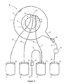
- Figures 1 and 2 show an example of a set of bags adapted to the separation of whole blood into a plasma component (essentially comprising plasma), a platelet component (essentially comprising platelets), a mononuclear cell component (comprising monocytes, lymphocytes and some red blood cells) and a red blood cell component (essentially comprising red blood cells and granulocytes).
- This bag set comprises a flexible separation bag 1 and four flexible satellite bags 2, 3, 4, 5 connected thereto.
- the separation bag 1 comprises an annular separation chamber 6 having generally circular outer and inner edges 7, 8. The outer circular edge 7 and the inner circular edge 8 of separation chamber 6 are substantially concentric.
- Separation chamber 6 comprises a first, acute-angled, funnel-like extension 9 protruding outwardly from its outer edge 7 for helping drain a content of the separation chamber 6 into satellite bag 5. Separation chamber 6 also comprises a second, obtuse-angled, funnel-like extension 10 protruding from inner edge 8, towards the center of bag 1, for helping funnel separated components into first, second and third satellite bags 2, 3, 4.
- Separation bag 1 further comprises a semi-flexible disk-shaped connecting element 11 that is connected to inner edge 8 of annular chamber 5.
- Disk-shaped connecting element 11 comprises three rounded recesses 12 on its inner edge facing second funnel-like extension 10, for partially surrounding three pinch valve members of a rotor of a centrifuge to be described later (diagrammatically shown in doted line in Figure 2 ).
- Disk-shaped connecting element 11 comprises a series of holes 13 for connecting separation bag 1 to the rotor of a centrifuge.
- Satellite bag 2 has two purposes, and is successively used as a whole blood collection bag and as a mononuclear cell component bag. Satellite bag 2 is intended for initially receiving a volume of whole blood from a donor (usually about 450 ml) before the separation process, and the mononuclear cell component during the separation process. Satellite bag 2 is flat, substantially rectangular, and comprises two reinforced ears at its upper corners having holes 14 for hanging the bag. It is connected to separation bag 1 by transfer tube 20 having a first end connected to the upper edge of satellite bag 2 and a second end connected to the second funnel-like extension 10, close to inner circular edge 8.
- Satellite bag 2 contains a volume of anti-coagulant solution (typically about 63 ml of a solution of citrate phosphate dextrose for a blood donation of about 450 ml).
- a frangible connector 21 mounted on transfer tube 20 blocks a liquid flow through transfer tube 20 and prevents the anti-coagulant solution from flowing from satellite bag 2 into separation bag 1.
- the bag set further comprises a collection tube 22 that is connected at one end to the upper edge of satellite bag 2 and comprises, at the other end, a needle protected by a sheath 23.
- Collection tube 22 is fitted with a clamp 24.
- Satellite bag 3 is intended for receiving a plasma component. Satellite bag 3 is flat, substantially rectangular, and comprises two reinforced ears at its upper corners having holes 14 for hanging the bag. It is connected by a transfer tube 25 to separation bag 1. Transfer tube 25 has a first end connected to the upper edge of satellite bag 3 and a second end connected to the second funnel-like extension 10, close to inner circular edge 8, opposite the second end of the first transfer tube 20 with respect to the tip of the second funnel-like extension 10.
- Satellite bag 4 is intended for receiving a platelet component. It is flat, substantially rectangular, and comprises two reinforced ears at its upper corners having holes 14 for hanging the bag. It is connected by a transfer tube 26 to the separation bag 1. Transfer tube 26 has a first end connected to the upper edge of satellite bag 4 and a second end connected to the tip of the second funnel-like extension 10.
- Satellite bag 5 is intended for receiving a red blood cell component. It is flat, substantially rectangular, and comprises two reinforced ears at its upper corners having holes 14 for hanging the bag. It is connected by a transfer tube 27 to separation bag 1. Transfer tube 27 has a first end connected to the upper edge of satellite bag 5 and a second end connected to the tip of the first funnel-like extension 9. It comprises two tube segments respectively connected to the inlet and the outlet of a leuko-reduction filter 28. The tube segment connected to separation bag 1 is fitted with a clamp 24. The tube segment connected to satellite bag 5 is fitted with a frangible connector 29, which, when broken, allows a flow of liquid between separation bag 1 and satellite bag 5.
- the filter may be, for example, a filter of the type RC2D manufactured by Pall Corporation.
- Such a filter comprises a disk-shaped casing to which radial inlet and outlet ports are connected, in diametrical opposition.
- the casing which is made of polycarbonate (GE Lexan HF 1140), has an internal volume of about 33 ml. It is filled with a filtering medium composed of multiple layers of a non-woven web of polyester fibers (about two micron diameter). It is understood, however, that other filters by other manufacturers can also be used.
- Satellite bag 5 contains a volume of storage solution for red blood cells.
- Variants of the separation bag 1 may include a separation chamber 6 having an outer circular edge 7 and/or an inner circular edge 8 that are eccentric.
- a separation chamber 6 may comprise a radial wall extending from inner edge 8 to outer edge 7 so that chamber 6, instead of being annular, is C-shaped.
- all the satellite bags may be connected to the inner edge of the separation bag.
- the separation bag 1 can be shaped so as to fit either on a flat support surface or on a frusto-conical support surface of the rotor of a centrifuge.
- the bags and the tubes of the bag set shown in Figures 1 and 2 are all made of flexible plastic material appropriate to contact blood and blood components.
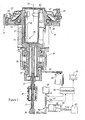
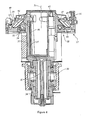
- FIGs 3 and 4 show an embodiment of an apparatus for separating a volume of composite liquid by centrifugation.
- the apparatus comprises a centrifuge adapted for receiving the set of separation bags shown in Figures 1 and 2 , and a component transferring means for causing the transfer of separated components into the satellite bags.
- the centrifuge comprises a rotor that is supported by a bearing assembly 30 allowing the rotor to rotate about a vertical central axis 31.
- the rotor comprises a cylindrical rotor shaft comprising a first upper portion 32 and a second lower portion 33; the upper portion 32 of the shaft extends in part through the bearing assembly 30; a pulley 34 is connected to the lower end of the upper portion 32 of the shaft; a central compartment 35 for containing satellite bags, which is connected to the rotor shaft 32, 33 at the upper end thereof; a support member 36 fitting within the central compartment 34, for supporting at least one satellite bag in a determined position within the central compartment 35; a circular turntable 37 for supporting a separation bag, which is connected to the compartment 35 at the upper end thereof, the central axes of the rotor shaft 32, 33, the compartment 35 and the turntable 37 coinciding with the rotation axis 31; and a balancing assembly 38, which is secured to the turntable 37.
- the centrifuge further comprises a motor 40 coupled to the rotor by a belt 41 engaged in a groove of the pulley 34 so as to rotate the rotor about the central vertical axis 31.
- the separation apparatus further comprises pinch valve members 42, 43, 44 that are mounted on the rotor for selectively blocking or allowing a flow of liquid through a flexible plastic tube, and selectively sealing and cutting a plastic tube.
- Each pinch valve member 42, 43, 44 comprises an elongated cylindrical body and a head having a groove that is defined by a stationary upper jaw and a lower jaw movable between an open and a closed position, the groove being dimensioned so that one of transfer tubes 20, 25, 26 of the bag sets shown in Figures 1 and 2 can be snuggly engaged therein when the lower jaw is in the open position.
- the elongated body contains a mechanism for moving the lower jaw and it is connected to a radio frequency generator that supplies the energy necessary for sealing and cutting a plastic tube.
- Pinch valve members 42, 43, 44 are mounted at the periphery of central compartment 35 so that their longitudinal axes are coplanar, and parallel to central axis 31 of the rotor, and their heads protrude above the rim of central compartment 35.
- the position of pinch valve members 42, 43, 44 with respect to separation bag 1 and transfer tubes 20, 25, 26 connected thereto when separation bag 1 is mounted on turntable 37 is shown in doted lines in Figure 2 .
- Electric power is supplied to pinch valve members 42, 43, 44 through a slip ring array 45 that is mounted around the lower portion 33 of the rotor shaft.
- Support member 36 generally comprises a portion of wall 46 that is tilted with respect to the rotation axis 31 of the rotor.
- a satellite bag secured by an upper portion thereof to an upper part of the tilted wall 46 is pressed against the tilted wall 46 by centrifugation forces during rotation of the rotor and a lower portion of the satellite bag is closer to the axis of rotation than an upper portion thereof.
- a liquid contained in the supported satellite bag drains from the supported satellite bag into the separation bag under centrifugation forces.
- Turntable 37 comprises a central frusto-conical portion 47, the upper, smaller edge of which is connected to the rim of compartment 35, an annular flat portion 48 connected to the lower, larger edge of the frusto-conical portion 47, and an outer cylindrical flange 49 extending upwards from the outer periphery of the annular portion 48.
- Turntable 35 further comprises a vaulted circular lid 50 that is secured to flange 49 by a hinge so as to pivot between an open and a closed position. Lid 50 is fitted with a lock 51 by which it can be blocked in the closed position.
- Lid 50 has an annular interior surface that is so shaped that, when lid 50 is in the closed position, it defines with the frusto-conical portion 47 and the annular flat portion 48 of the turntable 37 a frusto-conical annular compartment 52 having a radial cross-section that has substantially the shape of a parallelogram.
- the frusto-conical annular compartment 52 (later the "separation compartment"), which has a fixed volume, is intended for containing the separation bag 1 shown in Figures 1 and 2 .
- Balancing assembly 38 which has generally the shape of a ring, is mounted on the rotor within the space that extends between the upper end of central compartment 35 and the frusto-conical wall 47 of turntable 37.
- Balancing assembly 38 comprises a ring-shaped housing 53 defining a cavity whose cross-section, along a radial plane, is generally rectangular.
- the balancing assembly further comprises a plurality of ponderous balls 54 having a diameter that is slightly less than the radial depth of the cavity of housing 53. When the balls 54 are in contact with each other they occupy a sector of housing 52 of about 180 degrees.
- the component transferring means comprises a squeezing system for squeezing the separation bag within separation compartment 52 and causing the transfer of separated components into the satellite bags.
- the squeezing system comprises a flexible annular diaphragm 55 that is so shaped as to line the frusto-conical portion 47 and the annular flat portion 48 of turntable 37, to which it is secured along its smaller and larger circular edges.
- the squeezing system further comprises a hydraulic pumping station 60 for pumping a hydraulic liquid in and out an expandable hydraulic or squeezing chamber 56 defined between flexible diaphragm 55 and turntable 37, via a duct 57 extending through the rotor from the lower end of lower portion 33 of the rotor shaft to turntable 37.
- Pumping station 60 comprises a piston pump having a piston 61 movable in a hydraulic cylinder 62 fluidly connected via a rotary fluid coupling 58 to rotor duct 57.
- Piston 61 is actuated by a stepper motor 63 that moves a lead screw 64 linked to piston rod 61.
- Stepper motor 63 can be controlled by discrete increments or steps, each step corresponding to a fraction of turn of the axle of motor 63, a small linear displacement of piston 61, and a small determined volume of liquid being pumped in or out of hydraulic chamber 56.
- Hydraulic cylinder 62 is also connected to a hydraulic liquid reservoir 65 having an access controlled by a valve 66 for selectively allowing the introduction or the withdrawal of hydraulic liquid into and from a hydraulic circuit including hydraulic cylinder 62, rotor duct 57 and the expandable hydraulic chamber 56.
- a pressure gauge 67 is connected to the hydraulic circuit for measuring the hydraulic pressure therein.
- the separation apparatus further comprises four sensors 70, 71, 72, and 73 for detecting characteristics of the separation process occurring within a separation bag 1 when the apparatus operates.
- the four sensors 70, 71, 72, and 73 are embedded in lid 50 at different distances from the rotation axis 31 of the rotor, a sensor 73 being the closest to the rotation axis 31, a sensor 71 being the farthest to the rotation axis 31 and a sensor 72 and a sensor 70 occupying an intermediate position with sensor 70 being closer to the axis of rotation than sensor 72.
- the four sensors 70, 71, 72, and 73 face separation bag 1 as shown in Figure 2 .
- Sensor 70 is embedded in lid 50 so as to be positioned over separation chamber 6 a short distance from the end of tube 25 connected to the second funnel-like extension 10 (plasma outlet). Sensor 70 is able to detect an interface gas/liquid, an interface between plasma and a platelet/mononuclear cell layer, an interface between platelet rich plasma and mononuclear cells, as well as red blood cells. Sensor 71 (later the "outer sensor") is embedded in lid 50 so as to be positioned over separation chamber 6 at about two third of the width of the separation chamber from the inner edge, and it is offset with respect to the second funnel-like extension 10, while being closer to the end of the second transfer tube 25 than to the respective ends of transfer tubes 20, 26.
- Outer sensor 71 is able to detect a liquid, e.g ,. blood.
- Sensor 72 is embedded in lid 50 so as to be positioned over separation chamber 6 at about one third of the width of the separation chamber from inner edge 8 thereof.
- Sensor 72 is able to detect an interface between plasma and blood cells.
- Sensor 73, or the inner sensor, is positioned close to transfer tube 26 (platelet outlet). This sensor is able to detect the top of the red blood cell layer.
- Each sensor 70, 71, 72, and 73 can comprise a photocell including an infra-red LED and a photo-detector. Electric power is supplied to the sensors 70, 71, 72 through slip ring array 45.
- the separation apparatus further comprises a controller 80 including a control unit (microprocessor) and a memory for providing the microprocessor with information and programmed instructions relative to various separation protocols and to the operation of the apparatus in accordance with such separation protocols.
- the microprocessor is programmed for receiving information relative to the centrifugation speed(s) at which the rotor is to be rotated during the various stages of a separation process, and information relative to the various transfer flow rates at which separated components are to be transferred from the separation bag 1 into satellite bags 2, 3, 4.
- the information relative to the various transfer flow rates can be expressed, for example, as hydraulic liquid flow rates in the hydraulic circuit, or as rotation speeds of stepper motor 63 of hydraulic pumping station 60.
- the microprocessor is further programmed for receiving, directly or through the memory, information from pressure gauge 67 and from photocells 70, 71, 72, 73 and for controlling centrifuge motor 40, stepper motor 63, and pinch valve members 42, 43, 44 so as to cause the separation apparatus to operate along a selected separation protocol.
- Control unit 80 is also programmed for determining and displaying on a screen 81 of the separation apparatus the actual volume of the components separated during a separation procedure, as well as the actual volume of the composite liquid (for example, whole blood) initially contained in separation bag 1.
- the composite liquid for example, whole blood
- a first separation protocol aiming at the preparation of four blood components from a whole blood donation, namely a plasma component, a platelet component, a mononuclear cell component and a red blood cell component, is explained below.
- the protocol can be used for a three component collection with mononuclear cells being waste or even for at least a two component collection.
- First stage a bag set as shown in Figure 1, in which satellite bag 2 contains a volume of whole blood, is set in place in the rotor of a centrifuge (as shown in Figures 3, 4).
- satellite bag 2 of the bag set of Figure 1 contains a volume of anti-coagulated whole blood (usually about 500 ml). Collection tube 22 has been sealed and cut close to satellite bag 2. Clamp 24 on transfer tube 27 connecting satellite bag 5 to separation bag 1 is closed.
- the four satellite bags 2, 3, 4, 5 are superposed one upon another so as to form a stack that is inserted bag loader 36 so that satellite bag 2 is adjacent the tilted wall 46 of bag loader 36. Satellite bags 2, 3, 4, 5 are secured by their upper ears to an upper part of bag loader 36, above the tilted wall 46. In this position, they are substantially located on one side of a plane containing the rotation axis 31 of the rotor, and a lower portion of satellite bag 2 containing the volume of whole blood is closer to the rotation axis 31 than an upper portion thereof.
- Separation bag 1 is then laid on turntable 37 and pins (not shown) protruding on turntable 37 around the opening of central compartment 35 are engaged in holes 13 of the disk-shaped connecting element 11 of separation bag 1.
- Transfer tube 20 connecting satellite bag 2 to separation bag 1 is engaged in pinch valve member 42
- transfer tube 25 connecting satellite bag 3 to separation bag 1 is engaged in pinch valve member 43
- transfer tube 26 connecting satellite bag 4 to separation bag 1 is engaged in pinch valve member 44.
- Frangible connector 21 blocking communication between satellite bag 2 and separation bag 1 is broken. Lid 49 of the rotor is closed.
- Second stage the anti-coagulated whole blood contained in satellite bag 2 is transferred into the separation bag 1.
- pinch valve member 42 is open and pinch valve members 43, 44 are closed.
- the rotor is set in motion by centrifuge motor 40 and its rotation speed increases steadily until it reaches a first centrifugation speed (e.g. about 1500 RPM) that is so selected as to be high enough to cause the transfer, under centrifugation forces, of the content of satellite bag 2 into separation bag 1, so that the whole transfer happens in a short period of time; while, at the same time, to be low enough not to cause pressure within satellite bag 2 to substantially exceed a determined pressure threshold above which hemolysis would occur; and to be low enough not to generate shearing forces in the flow of blood entering separation bag 1 that would cause hemolysis.
- a first centrifugation speed e.g. about 1500 RPM
- the pressure threshold above which hemolysis occurs in satellite bag 2 is about 10 PSI, and that the maximum rotation speed at which such pressure threshold is not reached and the shearing forces in the blood flow entering the separation bag do not cause hemolysis is about 1800 RPM. At a rotation speed of about 1500 RPM, it takes about one minute for transferring about 500ml of anti-coagulated blood from satellite bag 2 into separation bag 1.
- valve member 43 controlling a flow of fluid through transfer tube 25 connected to satellite bag 3 (in which a plasma component will be later transferred) is opened for a predetermined amount of time (for example, about 30 seconds) so as to allow air to vent from separation bag 1 when blood pours therein.
- control unit 80 causes the rotor to stop and an alarm to be emitted. This could happen in particular if frangible connector 21 has inadvertently not been broken.
- Third stage the air present in separation bag 1 is purged into satellite bag 2, in which the mononuclear cell component is to be later transferred.
- Fourth stage the blood within the separation chamber is sedimented to a desired level.
- pinch valve members 42 and 43 are closed.
- the speed of the rotor is increased steadily until it reaches a second, high, centrifugation speed (for example, about 3200 RPM, so-called "hard spin") at which the blood components will sediment at the desired level.
- Pinch valve member 44 is open so that any additional air can be expelled to platelet bag 4.
- the pumping station is activated to pump hydraulic fluid at a constant flow rate to the hydraulic chamber to squeeze the separation bag 1. Squeezing continues until the hydraulic pressure is a predetermined variation from the constant pressure as described below.
- the rotor is rotated at the second centrifugation speed for a predetermined period of time (for example, about 220 seconds), which is selected so that, whatever the hematocrit of the whole blood initially transferred in the separation chamber 1, the blood sediments therein at the end of the predetermined period to a point where the hematocrit of the outer annular red blood cell layer is about 90 and the inner annular plasma layer is substantially devoid of cells.
- a predetermined period of time for example, about 220 seconds
- the separation bag 1 exhibits four layers: a first inner layer mainly comprising plasma, a second intermediate layer mainly comprising platelets, a third intermediate layer mainly comprising white blood cells (lymphocytes, monocytes and granulocytes), and a fourth outer layer mainly comprising red blood cells, wherein the third and fourth layers partially overlap (the granulocytes are in part embedded in the fourth layer).
- pinch valve member 42 and 43 are closed.
- Pinch valve member 44 remains open.
- the rotor continues to rotate at the same high centrifugation speed as in the sedimentation stage.
- pinch valve member 43 controlling access to satellite bag 3 is opened.
- Pumping station 60 is actuated so as to pump hydraulic liquid at a constant flow rate (for example, about 150-220 ml/min) into hydraulic chamber 56.
- the expanding hydraulic chamber 56 squeezes separation bag 1 and causes the transfer of plasma into satellite bag 3 and some plasma into transfer tube 26.
- Pinch valve 44 is closed at the turning point of increasing pressure to constant pressure as described below.
- the transfer flow rate of the plasma component (which is directly related to the flow rate of the hydraulic fluid or liquid) is selected to be as high as possible without disturbing the platelet layer so as to avoid contaminating the plasma component with platelets.
- Control unit 80 determines the volume of plasma that has been transferred into satellite bag 3 in the following manner: first, it determines when plasma actually starts pouring into satellite bag 3; second, it counts the number of steps performed by stepper motor 63 between the time plasma actually starts pouring into satellite bag 3, and the time pumping station 60 stops pumping hydraulic liquid into hydraulic chamber 56 after sensor 70 has detected an interface between plasma and the platelet/mononuclear cells; finally, the control unit 80 calculates, from the counted number of steps and the determined small volume associated to one step, the total volume of hydraulic liquid pumped into hydraulic chamber 56 during this stage, which corresponds to the volume of plasma in satellite bag 3.
- Control unit 80 determines when plasma actually starts pouring into satellite bag 3, in the following manner: it continuously records discrete successive values of the pressure of the hydraulic liquid as measured by pressure sensor 67, and it simultaneously analyses how the pressure evolves, for example by calculating, each time a new pressure value is recorded, from the average of the last four measured values, the slope of a curve representing the evolution of the pressure with respect to time, and by comparing the series of slopes so calculated; control unit 80 determines the point in time at which plasma start pouring into satellite bag 3 as corresponding to a drastic turning point between a first phase of steadily increasing pressure and a second phase of substantially constant pressure. This constant pressure as determined by pressure gauge 37 is recorded in the controller as pressure P. This turning point is also the signal for the control unit 80 to close valve 44.
- Control unit 80 can be programmed to cause the actual volume of plasma in satellite bag 3, once determined, to be displayed on screen 81.
- Control unit 80 also determines the volume of anti-coagulated whole blood that has been transferred into separation bag 1 during the second stage, in the following manner: it first counts the number of steps performed by stepper motor 63 between the time pumping station 60 starts pumping hydraulic fluid into hydraulic chamber 56 at the third stage (transfer of air into satellite bag 2), and the time when plasma actually starts pouring into satellite bag 3, as determined above; second, control unit 80 calculates, from the counted number of steps and the determined small volume associated to one step, the total volume of hydraulic liquid pumped into hydraulic chamber 56 until separation compartment 52 does not contain air anymore; finally, control unit 80 calculates the volume of anti-coagulated blood that is in separation chamber 1, by subtracting the volume of hydraulic liquid so calculated from a fixed volume, stored in the memory of control unit 80. This fixed volume corresponds to the fixed volume of separation compartment 52, minus the volume of diaphragm 55, minus the volume of the two superposed rings of plastic sheet delimiting separation chamber 6, and minus a fixed residual volume of hydraulic liquid in hydraulic chamber 56.
- Control unit 80 can be programmed to cause the actual volume of anti-coagulated blood in separation bag 1, once determined, to be displayed on screen 81.
- Pinch valve member 44 controlling the access to satellite bag 4 is open and pinch valve member 42, 43 remain closed.
- the rotor continues to rotate at 3200 rpm.
- Pumping station 60 is actuated so as to pump hydraulic liquid at a first platelet flow rate into hydraulic chamber 56 and consequently squeeze separation bag 1 and cause the transfer of the platelet component and the smaller fraction of the plasma component in tube 26 into satellite bag 4.
- the first platelet flow rate for the platelets (for example, about 15 ml/min) is substantially lower than the flow rate (for example, about 150-220 ml/min) at which the plasma component is transferred into satellite bag 3 in the fifth stage.
- the first transfer flow rate of the platelet component (which is directly related to the first flow rate of the hydraulic fluid) is selected to be high enough for preventing the suspended platelets from sedimenting, without, at the same time, triggering the activation of the platelets.
- Control unit 80 determines the volume of the platelet component that has been transferred into satellite bag 4 at this point in the procedure in the following manner: it first counts the number of steps performed by stepper motor 63 between the time pumping station 60 starts pumping hydraulic fluid into hydraulic chamber 56 following the opening of pinch valve member 44, and the time pumping station 60 is stopped after sensor 73 has detected the interface between the suspended platelets and the mononuclear/red blood cells; second, control unit 80 calculates, from the counted number of steps and the determined small volume associated to one step, the total volume of hydraulic liquid pumped into hydraulic chamber 56 during this stage, which corresponds to the volume of the platelet component transferred to satellite bag 4. This volume is stored in the control unit 80 memory.
- Vx is selected by the controller based on final desired platelet volume as will be more fully explained with respect to the expression or spurt of platelets below. Vx can be indicative of the final plasma concentration in the final platelet product. Variations of Vx can be used to vary the plasma content and to provide plasma rich platelets.
- the reverse pumping of hydraulic pumping station 60 is stopped, the rotor speed is increased to 3200, and pinch valve 43 is opened.
- the returned plasma remixes with the platelets and red blood cells to assure any residual platelets are separated from the red blood cells. At this hard spin the red blood cells sediment out rapidly into a red blood cell layer.
- valves 42, 43, and 44 are closed.
- the rotor continues to rotate at a hard spin or approximately 3200 rpm.
- Hydraulic pumping station 60 is activated to return hydraulic fluid to hydraulic or squeezing chamber 56.
- Hydraulic chamber 56 receives hydraulic fluid until the pressure exerted on separation bag 1 is pressure P plus ⁇ P. That is, the pressure is raised higher than the constant pressure for expression to assure that the separation bag 1 is at a pressure for rapid expression or spurting as will be more fully explained below.
- Control unit 80 determines the volume of the spurted platelet and plasma component that is transferred into satellite bag 4 at this point in the procedure in the following manner: it first counts the number of steps performed by stepper motor 63 between the time pumping station 60 starts pumping hydraulic fluid into hydraulic chamber 56 until the pressure on the separation bag 1 is P and ⁇ P and the pinch valve member 44 is opened. The control unit 80 calculates, from the counted number of steps and the determined small volume associated to one step, the total volume of hydraulic liquid pumped into hydraulic chamber 56 during this stage, which corresponds to the volume of the platelet with any plasma component rapidly expressed or transferred to satellite bag 4 during this stage. This volume is stored in the control unit 80 memory.
- Pinch valve 44 remains open. Hydraulic pumping station 60 is ramped up to provide a low flow rate of the remaining platelets/plasma or plasma rich platelets of approximately 15 ml/min until a predetermined time after the top of the red blood cell layer is detected by inner photocell 73. The predetermined time assures that the maximum number of platelets will be collected. The centrifuge or rotor continues to rotate at 3200 rpm. After the predetermined time, pinch valve 44 is closed and platelet collection is completed.
- Control unit 80 determines the volume of the platelet component that has been transferred into satellite bag 4 during this stage in the following manner: it first counts the number of steps performed by stepper motor 63 between the time pumping station 60 is ramped up to start pumping hydraulic fluid into hydraulic chamber 56 and the time pumping station 60 is stopped after sensor 73 has detected the interface between the suspended platelets and the mononuclear/red blood cells; second, control unit 80 calculates, from the counted number of steps and the determined small volume associated to one step, the total volume of hydraulic liquid pumped into hydraulic chamber 56 during this stage, which corresponds to the volume of the platelet component transferred to satellite bag 4 during this stage.
- control unit 80 retrieves and adds the determined volumes from the platelet collections in the sixth, tenth and eleventh stages.
- the control unit 80 can be programmed to display this total volume on the display screen 81.
- Twelfth stage (first protocol): a mononuclear cell component is transferred into satellite bag 2.
- the twelfth stage can start as soon as pinch valve member 44 is closed at the end of the eleventh stage.
- the three pinch valve members 42, 43, 44 are closed.
- the rotor is rotated at the same centrifugation speed as previously with the flow rate being adjusted by hydraulic pumping station 60.
- Pinch valve member 42 controlling the access to satellite bag 2 is opened and hydraulic pumping system 60 is actuated so as to pump hydraulic liquid at a constant flow rate (for example, about 60 ml/min) into hydraulic chamber 56.
- the expanding hydraulic chamber 56 squeezes separation bag 1 and causes the transfer, into first satellite bag 2, of a mononuclear cell component comprising lymphocytes, monocytes, and a small amount of red blood cells.
- Pumping system 60 is stopped and pinch valve member 42 is closed after a predetermined volume (e.g., between 10 and 20 ml) has been transferred into satellite bag 2.
- a predetermined volume e.g., between 10 and 20 ml
- the rotor continues to rotate at 3200 rpm to maintain separation between the red blood cell and mononuclear cell layers.
- Control unit 80 determines the actual volume of the mononuclear cell component in satellite bag 2 by adding the volume of the mononuclear cell component actually transferred into satellite bag 2, which volume corresponds to the number of steps performed by the stepper motor between the opening and the closing of pinch valve member 42, to an empirically determined volume of whole blood remaining in satellite bag 2, which is stored in the memory of the control unit.
- Control unit 80 can be programmed to cause the actual volume of the mononuclear cell component in satellite bag 2, once determined, to be displayed on screen 81.
- the rotation speed of the rotor is decreased until the rotor stops, pumping system 60 is actuated and reversed so as to pump the hydraulic liquid from hydraulic chamber 56 at a high flow rate (for example, about 800 ml/min) until hydraulic chamber 56 is substantially empty, and pinch valve members 42, 43, 44 are actuated so as to seal and cut transfer tubes 20, 25, 26. Red blood cells remain in separation bag 1.
- a high flow rate for example, about 800 ml/min
- Control unit 80 determines the volume of red blood cells remaining in separation bag 1 by subtracting, from the previously determined volume of anti-coagulated whole blood the previously determined volumes of plasma component, platelet component and mononuclear cell component.
- Lid 50 of the rotor is opened and separation bag 1 connected to satellite bag 5 is removed therefrom.
- Clamp 24 on transfer tube 27 is opened.
- Frangible connector 29 blocking communication between satellite bag 5 and leuko-reduction filter 28 is broken.
- the storage solution contained in satellite bag 5 is allowed to flow by gravity through filter 28 and into separation bag 1 where it is mixed with the red blood cells so as to lower the viscosity thereof.
- the content of separation bag 1 is then allowed to flow by gravity drain through filter 28 and into satellite bag 5.
- the white blood cells granulocytes and residual monocytes and lymphocytes
- Control unit 80 can also determine the volume of red blood cells in satellite bag 5, which will result from the actual subsequent transfer of red blood cells from separation bag 1 into satellite bag 5 at the outcome of the fourteenth stage of the first separation protocol.
- Control unit 80 calculates the volume of red blood cells by subtracting, from the previously determined volume of anti-coagulated whole blood, the previously determined volumes of plasma component, platelet component, mononuclear cell component, and the internal volume of leuko-reduction filter 28, and adding to the result the known volume of red blood cell storage solution contained in satellite bag 5.
- Control unit 80 can be programmed to cause either one of the actual volume of the red blood cell component in separation bag 1 and the actual volume of the red blood cell component in satellite bag 5, or both, once determined, to be displayed on screen 81.
Landscapes
- Health & Medical Sciences (AREA)
- Heart & Thoracic Surgery (AREA)
- Vascular Medicine (AREA)
- Biomedical Technology (AREA)
- Engineering & Computer Science (AREA)
- Anesthesiology (AREA)
- Hematology (AREA)
- Life Sciences & Earth Sciences (AREA)
- Animal Behavior & Ethology (AREA)
- General Health & Medical Sciences (AREA)
- Public Health (AREA)
- Veterinary Medicine (AREA)
- Cardiology (AREA)
- External Artificial Organs (AREA)
- Centrifugal Separators (AREA)
Claims (16)
- Verfahren zum Trennen einer zusammengesetzten Flüssigkeit in mindestens eine erste Komponente und eine zweite Komponente, wobei das Verfahren umfasst:Zentrifugieren eines Trennbeutels (6), der ein Volumen einer zusammengesetzten Flüssigkeit enthält, sodass die Sedimentation von mindestens einer ersten Komponente und einer zweiten Komponente bewirkt wird;Pressen des Trennbeutels (6), um etwas von der zweiten Komponente zu einer ersten Übertragungsleitung (26) zu übertragen, die an einem ersten Übertragungsbeutel (4) und dem Trennbeutel (6) angebracht ist;Stoppen der Übertragung der zweiten Komponente zur ersten Übertragungsleitung (26);Pressen des Trennbeutels (6) nach dem Stoppschritt, um einen Überdruck im Trennbeutel (6) aufzubauen; undÜbertragen eines Teils der zweiten Komponente, die im Trennbeutel (6) verblieben ist, zum ersten Übertragungsbeutel (4) durch die erste Übertragungsleitung (26) unter Verwendung des Überdrucks, wobei der Überdruck bewirkt, dass sich die zweite Komponente schnell zum ersten Übertragungsbeutel (4) bewegt.
- Verfahren nach Anspruch 1, weiter umfassend das Pressen von etwas von der ersten Komponente vom Trennbeutel in einen zweiten Übertragungsbeutel vor dem Pressschritt, um einen Überdruck aufzubauen.
- Verfahren nach Anspruch 2, wobei die Schritte des Pressens, um die erste und zweite Komponente zu übertragen, das Vorwärtsbewegen einer Hydraulikanlage umfassen, um zu bewirken, dass Hydraulikflüssigkeit den Trennbeutel presst.
- Verfahren nach Anspruch 3, weiter umfassend
Umkehren der Hydraulikanlage, um die Hydraulikflüssigkeit umzukehren und das Pressen des Trennbeutels zu reduzieren;
Übertragen von etwas von der ersten Komponente vom zweiten Übertragungsbeutel zurück zum Trennbehälter nach dem Umkehrschritt; und
neu Mischen jeder ersten und zweiten Komponente im Trennbeutel. - Verfahren nach Anspruch 4, wobei die Umkehr- und Neumischschritte nach dem Stoppschritt erfolgen.
- Verfahren nach irgendeinem der vorhergehenden Ansprüche, wobei das Verfahren zum Trennen der zusammengesetzten Flüssigkeit in mindestens erste, zweite und dritte Komponenten dient, wobei der Zentrifugierschritt weiter die Sedimentation von mindestens der ersten, zweiten und dritten Komponenten bewirkt.
- Verfahren nach irgendeinem der vorhergehenden Ansprüche, wobei das Verfahren zum Trennen der zusammengesetzten Flüssigkeit in vier Komponenten dient, wobei der Zentrifugierschritt weiter die Sedimentation von mindestens ersten, zweiten, dritten und vierten Komponenten bewirkt.
- Verfahren nach irgendeinem der vorhergehenden Ansprüche, wobei die zweite Komponente Blutplättchen umfasst und die erste Komponente Plasma umfasst.
- Verfahren nach Anspruch 7, wobei die erste Komponente Plasma umfasst, die zweite Komponente Blutplättchen umfasst, die dritte Komponente mononukleäre Zellen umfasst und die vierte Komponente rote Blutkörperchen umfasst.
- Verfahren nach irgendeinem der vorhergehenden Ansprüche, wobei der Zentrifugierschritt umfasst:Drehen einer Zentrifuge mit ausreichenden Umdrehungen pro Minute für eine starke Drehung, um Sedimentation zu bewirken; undwobei der Pressschritt, um etwas von der zweiten Komponente zu übertragen, bei ca. den gleichen Umdrehungen pro Minute für die starke Drehung auftritt.
- Verfahren nach irgendeinem der vorhergehenden Ansprüche, weiter umfassend das Erkennen, wann die zusammengesetzte Flüssigkeit im Trennbeutel ist.
- Verfahren nach irgendeinem der vorhergehenden Ansprüche, weiter umfassend das Erkennen der Grenzschicht zwischen den ersten und zweiten Komponenten.
- Verfahren nach Anspruch 1, wobei das Verfahren zum Anpassen der Plasmakonzentration eines Blutplättchenproduktes dient, wobei die erste Komponente eine Plasmakomponente ist und die zweite Komponente eine Blutplättchenkomponente ist;
wobei der Trennbeutel (6) mit der Hydraulikflüssigkeit in einer Presskammer (56) gepresst wird, um etwas von der Plasmakomponente zu einem Plasmaübertragungsbeutel (3) zu übertragen;
wobei der erste Übertragungsbeutel ein Blutplättchenübertragungsbeutel ist;
wobei der Trennbeutel (6) mit Hydraulikflüssigkeit in einer Presskammer (56) gepresst wird, um etwas von der Blutplättchenkomponente zum Blutplättchenübertragungsbeutel (4) zu übertragen;
wobei das Verfahren weiter umfasst:Umkehren von mindestens einem der Pressschritte durch Entfernen eines Hydraulikflüssigkeitsvolumens aus der Presskammer (56);Rückführen eines Volumens der Plasmakomponente, die mit dem Volumen der entfernten Hydraulikflüssigkeit in Zusammenhang steht, zum Trennbeutel (6);neu Mischen des zurückgeführten Plasmavolumens mit den restlichen Blutplättchen im Trennbeutel (6); undPressen des Trennbeutels (6), um gemischte Blutplättchen und Plasma zum Blutplättchenübertragungsbeutel (4) zu übertragen. - Verfahren nach Anspruch 13, weiter umfassend
das Anpassen der Menge an Plasma, die zurückzuführen und mit den Blutplättchen im Trennbeutel zu mischen ist, durch Anpassen der Menge an zu entfernender Hydraulikflüssigkeit. - Verfahren nach Anspruch 13, wobei der Schritt des Pressens um einen Überdruck aufzubauen, umfasst
Pressen des Trennbeutels (6) mit der Hydraulikflüssigkeit, während des Verhinderns der Übertragung irgendwelcher Komponenten vom Trennbeutel (6). - Vorrichtung zum Trennen einer zusammengesetzten Flüssigkeit in mindestens eine erste Komponente und eine zweite Komponente, wobei die Vorrichtung umfasst:einen Trennsatz (1), umfassend:einen Trennbeutel (6);einen ersten Übertragungsbeutel (2, 3, 4);einen ersten Übertragungsschlauch (20, 25, 26), der den ersten Übertragungsbeutel (2, 3, 4) mit dem Trennbeutel (6) verbindet;einen Rotor für das Aufnehmen des Trennsatzes (1), wobei sich der Trennsatz (1) auf dem Rotor befindet, und wobei der Rotor umfasst:ein erstes Ventil (42, 43, 44) für das Empfangen des ersten Übertragungsschlauches (20, 25, 26);einen Motor (40), um den Rotor zu drehen, um die Sedimentation von mindestens einer ersten Komponente und einer zweiten Komponente im Trennbeutel (6) herbeiführen;eine Pressvorrichtung (56) für das Bereitstellen von Pressdruck an den Trennbeutel (6), um mindestens eine der getrennten Komponenten vom Trennbeutel (6) durch den ersten Übertragungsschlauch (20, 25, 26) zum ersten Übertragungsbeutel (2, 3, 4) zu pressen;einen Controller (80) für das Steuern des Drehens des Rotors und der Pressvorrichtung (56), wobei der Controller programmiert ist zum:Zentrifugieren des Trennbeutels (6), der ein Volumen einer zusammengesetzten Flüssigkeit enthält, sodass die Sedimentation von mindestens einer ersten Komponente und einer zweiten Komponente bewirkt wird;Pressen des Trennbeutels (6), um etwas von der zweiten Komponente zu einer ersten Übertragungsleitung (26) zu übertragen, die an einem ersten Übertragungsbeutel (4) und dem Trennbeutel (6) angebracht ist;Stoppen der Übertragung der zweiten Komponente zur ersten Übertragungsleitung (26);Pressen des Trennbeutels (6) nach dem Stoppschritt, um einen Überdruck im Trennbeutel (6) aufzubauen; undÜbertragen eines Teils der zweiten Komponente, die im Trennbeutel (6) verblieben ist, zum ersten Übertragungsbeutel (4) durch die erste Übertragungsleitung (26) unter Verwendung des Überdrucks, wobei der Überdruck bewirkt, dass die zweite Komponente schnell zum ersten Übertragungsbeutel (4) bewegt wird.
Priority Applications (3)
| Application Number | Priority Date | Filing Date | Title |
|---|---|---|---|
| EP14162842.0A EP2764878B1 (de) | 2007-05-14 | 2007-10-31 | Vorrichtung zum Auftrennen von Blut in vier Bestandteile |
| EP14162845.3A EP2764879B1 (de) | 2007-05-14 | 2007-10-31 | Vorrichtung und Verfahren zum Gewinnen von vier Bestandteilen aus einem zusammengesetzten Blutprodukt |
| EP14162848.7A EP2764880B1 (de) | 2007-05-14 | 2007-10-31 | Vorrichtung und Verfahren zum Trennen einer Verbundstoffflüssigkeit in mindestens zwei Bestandteile |
Applications Claiming Priority (2)
| Application Number | Priority Date | Filing Date | Title |
|---|---|---|---|
| US91779407P | 2007-05-14 | 2007-05-14 | |
| PCT/US2007/083204 WO2008140561A1 (en) | 2007-05-14 | 2007-10-31 | Apparatus and method for separating a composite liquid into at least two components |
Related Child Applications (6)
| Application Number | Title | Priority Date | Filing Date |
|---|---|---|---|
| EP14162845.3A Division EP2764879B1 (de) | 2007-05-14 | 2007-10-31 | Vorrichtung und Verfahren zum Gewinnen von vier Bestandteilen aus einem zusammengesetzten Blutprodukt |
| EP14162845.3A Division-Into EP2764879B1 (de) | 2007-05-14 | 2007-10-31 | Vorrichtung und Verfahren zum Gewinnen von vier Bestandteilen aus einem zusammengesetzten Blutprodukt |
| EP14162848.7A Division EP2764880B1 (de) | 2007-05-14 | 2007-10-31 | Vorrichtung und Verfahren zum Trennen einer Verbundstoffflüssigkeit in mindestens zwei Bestandteile |
| EP14162848.7A Division-Into EP2764880B1 (de) | 2007-05-14 | 2007-10-31 | Vorrichtung und Verfahren zum Trennen einer Verbundstoffflüssigkeit in mindestens zwei Bestandteile |
| EP14162842.0A Division EP2764878B1 (de) | 2007-05-14 | 2007-10-31 | Vorrichtung zum Auftrennen von Blut in vier Bestandteile |
| EP14162842.0A Division-Into EP2764878B1 (de) | 2007-05-14 | 2007-10-31 | Vorrichtung zum Auftrennen von Blut in vier Bestandteile |
Publications (2)
| Publication Number | Publication Date |
|---|---|
| EP2155286A1 EP2155286A1 (de) | 2010-02-24 |
| EP2155286B1 true EP2155286B1 (de) | 2015-07-22 |
Family
ID=39253933
Family Applications (4)
| Application Number | Title | Priority Date | Filing Date |
|---|---|---|---|
| EP07863724.6A Active EP2155286B1 (de) | 2007-05-14 | 2007-10-31 | Gerät und verfahren zur auftrennung einer zusammengesetzten flüssigkeit in wenigstens zwei komponenten |
| EP14162845.3A Not-in-force EP2764879B1 (de) | 2007-05-14 | 2007-10-31 | Vorrichtung und Verfahren zum Gewinnen von vier Bestandteilen aus einem zusammengesetzten Blutprodukt |
| EP14162842.0A Active EP2764878B1 (de) | 2007-05-14 | 2007-10-31 | Vorrichtung zum Auftrennen von Blut in vier Bestandteile |
| EP14162848.7A Not-in-force EP2764880B1 (de) | 2007-05-14 | 2007-10-31 | Vorrichtung und Verfahren zum Trennen einer Verbundstoffflüssigkeit in mindestens zwei Bestandteile |
Family Applications After (3)
| Application Number | Title | Priority Date | Filing Date |
|---|---|---|---|
| EP14162845.3A Not-in-force EP2764879B1 (de) | 2007-05-14 | 2007-10-31 | Vorrichtung und Verfahren zum Gewinnen von vier Bestandteilen aus einem zusammengesetzten Blutprodukt |
| EP14162842.0A Active EP2764878B1 (de) | 2007-05-14 | 2007-10-31 | Vorrichtung zum Auftrennen von Blut in vier Bestandteile |
| EP14162848.7A Not-in-force EP2764880B1 (de) | 2007-05-14 | 2007-10-31 | Vorrichtung und Verfahren zum Trennen einer Verbundstoffflüssigkeit in mindestens zwei Bestandteile |
Country Status (4)
| Country | Link |
|---|---|
| US (1) | US8236184B2 (de) |
| EP (4) | EP2155286B1 (de) |
| JP (1) | JP5161301B2 (de) |
| WO (1) | WO2008140561A1 (de) |
Families Citing this family (18)
| Publication number | Priority date | Publication date | Assignee | Title |
|---|---|---|---|---|
| JP5405313B2 (ja) * | 2006-12-20 | 2014-02-05 | テルモ ビーシーティー、インコーポレーテッド | 複合液体を少なくとも2つの成分に分離するための機器および方法 |
| WO2009134521A1 (en) * | 2008-05-02 | 2009-11-05 | Caridianbct, Inc. | Centrifuge apparatus and method for selectively reducing forces on a biologic fluid |
| WO2010014330A2 (en) * | 2008-07-31 | 2010-02-04 | Caridianbct, Inc. | Method and apparatus for determining the yield of at least one component |
| US9327296B2 (en) | 2012-01-27 | 2016-05-03 | Fenwal, Inc. | Fluid separation chambers for fluid processing systems |
| US8803090B2 (en) | 2012-11-09 | 2014-08-12 | Fenwal, Inc. | Citrate detector for blood processing system |
| US9968738B2 (en) | 2014-03-24 | 2018-05-15 | Fenwal, Inc. | Biological fluid filters with molded frame and methods for making such filters |
| US9782707B2 (en) | 2014-03-24 | 2017-10-10 | Fenwal, Inc. | Biological fluid filters having flexible walls and methods for making such filters |
| US10159778B2 (en) | 2014-03-24 | 2018-12-25 | Fenwal, Inc. | Biological fluid filters having flexible walls and methods for making such filters |
| US10376627B2 (en) | 2014-03-24 | 2019-08-13 | Fenwal, Inc. | Flexible biological fluid filters |
| US9796166B2 (en) | 2014-03-24 | 2017-10-24 | Fenwal, Inc. | Flexible biological fluid filters |
| EP2987515A1 (de) * | 2014-08-19 | 2016-02-24 | Reapplix APS | Zentrifuge und Verfahren zum Zentrifugieren einer Blutprobe |
| JP6714310B2 (ja) | 2015-02-20 | 2020-06-24 | テルモ ビーシーティー、インコーポレーテッド | 複合液体バッグシステムホルダ |
| EP3124063B1 (de) | 2015-07-29 | 2019-04-10 | Fenwal, Inc. | Bluttrennkammer mit fünf anschlüssen und verfahren zur verwendung davon |
| WO2018094310A1 (en) * | 2016-11-18 | 2018-05-24 | Bullington Gregory J | Systems and methods for sample collection with reduced hemolysis |
| WO2018102823A1 (en) | 2016-12-02 | 2018-06-07 | Terumo Bct, Inc | Composite fluid separation |
| WO2018129467A1 (en) * | 2017-01-08 | 2018-07-12 | Cesca Therapeutics, Inc. | Devices and methods for bio-processing cellular samples |
| EP3533522A1 (de) * | 2018-02-28 | 2019-09-04 | Alfa Laval Corporate AB | Zentrifugalabscheider und verfahren zum betrieb eines zentrifugalabscheiders |
| US12343738B2 (en) | 2021-04-05 | 2025-07-01 | Fenwal, Inc. | Continuous flow centrifugation chambers |
Family Cites Families (47)
| Publication number | Priority date | Publication date | Assignee | Title |
|---|---|---|---|---|
| UST955355I4 (de) | 1959-06-24 | 1900-01-01 | ||
| US3326458A (en) | 1965-05-28 | 1967-06-20 | Harold T Meryman | Container and process of storing blood |
| BE754683A (fr) | 1969-08-11 | 1971-01-18 | Aga Ab | Recipient destine a contenir du sang |
| SE332906B (de) | 1969-08-11 | 1971-02-22 | Aga Ab | |
| US3724747A (en) | 1971-03-15 | 1973-04-03 | Aga Ab | Centrifuge apparatus with means for moving material |
| US3737096A (en) | 1971-12-23 | 1973-06-05 | Ibm | Blood processing control apparatus |
| JPS50107565A (de) | 1974-01-29 | 1975-08-25 | ||
| US4146172A (en) | 1977-10-18 | 1979-03-27 | Baxter Travenol Laboratories, Inc. | Centrifugal liquid processing system |
| US4187979A (en) * | 1978-09-21 | 1980-02-12 | Baxter Travenol Laboratories, Inc. | Method and system for fractionating a quantity of blood into the components thereof |
| US4405079A (en) | 1980-11-10 | 1983-09-20 | Haemonetics Corporation | Centrifugal displacer pump |
| US4389207A (en) | 1981-03-16 | 1983-06-21 | Baxter Travenol Laboratories, Inc. | Rotatable bowl assembly for centrifugal processing apparatus having a bonded and prewound umbilical system |
| US4421503A (en) | 1981-07-09 | 1983-12-20 | Haemonetics Corporation | Fluid processing centrifuge and apparatus thereof |
| US4482342A (en) | 1982-06-17 | 1984-11-13 | Haemonetics Corporation | Blood processing system for cell washing |
| DE3786263T2 (de) | 1986-05-16 | 1994-01-05 | Omega Medicinteknik Ab | Vorrichtung zur Plasmaphorese. |
| US4720284A (en) | 1986-10-03 | 1988-01-19 | Neotech, Inc. | Method and means for separation of blood components |
| US4850995A (en) | 1987-08-19 | 1989-07-25 | Cobe Laboratories, Inc. | Centrifugal separation of blood |
| SE462015B (sv) | 1987-09-15 | 1990-04-30 | Omega Medicinteknik Ab | Saett och anordning foer tvaettning av blodceller |
| SE9002255D0 (sv) | 1990-06-26 | 1990-06-26 | Eric Westberg | Metod och anordning vid framstaellning av blod |
| US5092996A (en) | 1991-02-19 | 1992-03-03 | Miles Inc. | Blood filtering system |
| JP3231086B2 (ja) | 1992-06-30 | 2001-11-19 | テルモ株式会社 | 液体分離装置 |
| DE69324754T2 (de) | 1992-10-07 | 2000-01-13 | Asahi Medical Co. Ltd., Tokio/Tokyo | Filter und System zur Trennung der Leukozyten |
| SE9302369D0 (sv) | 1993-07-08 | 1993-07-08 | Omega Medicinteknik Ab | Paassystem avsett foer centrifugalseparationsamt an vaendning av detta paassystem |
| US5427695A (en) | 1993-07-26 | 1995-06-27 | Baxter International Inc. | Systems and methods for on line collecting and resuspending cellular-rich blood products like platelet concentrate |
| US5733253A (en) | 1994-10-13 | 1998-03-31 | Transfusion Technologies Corporation | Fluid separation system |
| SE505621C2 (sv) | 1995-03-21 | 1997-09-22 | Omega Medicinteknik Ab | Sätt och extraktor för buffycoatskördning från centrifugerade kolaberbara blodbehållare |
| US5738644A (en) | 1995-06-07 | 1998-04-14 | Cobe Laboratories, Inc. | Extracorporeal blood processing methods and apparatus |
| JPH09108594A (ja) * | 1995-10-16 | 1997-04-28 | Terumo Corp | 遠心分離器および成分分離方法 |
| US5769811A (en) | 1995-10-31 | 1998-06-23 | Haemonetics Corporation | Blood-processing machine system |
| US5964724A (en) | 1996-01-31 | 1999-10-12 | Medtronic Electromedics, Inc. | Apparatus and method for blood separation |
| US5637082A (en) | 1996-02-22 | 1997-06-10 | Haemonetics Corporation | Adaptive apheresis apparatus |
| SE9600713L (sv) | 1996-02-26 | 1997-10-17 | Omega Medicinteknik Ab | Metod för separering av celler, speciellt blodplättar och pås-set därför |
| SE9700495D0 (sv) | 1997-02-12 | 1997-02-12 | Omega Medicinteknik Ab | Metod och rundpåsesystem samt centrifug för behandling av blod |
| SE9701423D0 (sv) | 1997-04-16 | 1997-04-16 | Omega Medicinteknik Ab | Behållarset och anordning för blodseparation |
| DE69834185T2 (de) | 1997-05-20 | 2007-01-25 | Zymequest, Inc., Beverly | Optische Sensoren für Zellbehandlungssysteme |
| US6296602B1 (en) | 1999-03-17 | 2001-10-02 | Transfusion Technologies Corporation | Method for collecting platelets and other blood components from whole blood |
| SE516321C2 (sv) | 1999-05-31 | 2001-12-17 | Gambro Inc | Centrifug för behandling av blod och blodkomponenter |
| US6284142B1 (en) * | 1999-09-03 | 2001-09-04 | Baxter International Inc. | Sensing systems and methods for differentiating between different cellular blood species during extracorporeal blood separation or processing |
| SE517032C2 (sv) | 1999-10-26 | 2002-04-02 | Gambro Inc | Sätt och anordning för behandling av blod och blodkomponenter |
| WO2001097943A1 (en) | 2000-06-20 | 2001-12-27 | Medicept, Inc. | Blood component preparation (bcp) device and method of use thereof |
| JP4832683B2 (ja) * | 2001-09-19 | 2011-12-07 | テルモ株式会社 | 血小板採取装置 |
| EP1494735B1 (de) | 2002-04-16 | 2008-01-02 | Gambro BCT, Inc. | System und verfahren zur aufarbeitung von blutbestandteilen |
| ATE528032T1 (de) | 2002-08-23 | 2011-10-15 | Caridianbct Inc | Beutelset zur auftrennung einer flüssigkeit aus mehreren komponenten in einer zentrifuge |
| US7347932B2 (en) * | 2003-08-25 | 2008-03-25 | Gambro Bct, Inc. | Apparatus and method for separating a volume of composite liquid into at least two components |
| JP2005110748A (ja) * | 2003-10-03 | 2005-04-28 | Terumo Corp | 血液成分採取装置 |
| JP4938465B2 (ja) | 2004-02-20 | 2012-05-23 | カリディアンビーシーティー、インコーポレーテッド | 多量の混成液体を少なくとも2つの成分に分離する装置及び方法 |
| DE602005018443D1 (de) * | 2004-12-28 | 2010-02-04 | Caridianbct Inc | Apparat und Methode zur Separation einer Menge Blut in vier Komponenten |
| US7442178B2 (en) * | 2005-03-09 | 2008-10-28 | Jacques Chammas | Automated system and method for blood components separation and processing |
-
2007
- 2007-10-31 EP EP07863724.6A patent/EP2155286B1/de active Active
- 2007-10-31 EP EP14162845.3A patent/EP2764879B1/de not_active Not-in-force
- 2007-10-31 EP EP14162842.0A patent/EP2764878B1/de active Active
- 2007-10-31 US US11/931,582 patent/US8236184B2/en not_active Expired - Fee Related
- 2007-10-31 JP JP2010508355A patent/JP5161301B2/ja active Active
- 2007-10-31 EP EP14162848.7A patent/EP2764880B1/de not_active Not-in-force
- 2007-10-31 WO PCT/US2007/083204 patent/WO2008140561A1/en not_active Ceased
Also Published As
| Publication number | Publication date |
|---|---|
| WO2008140561A1 (en) | 2008-11-20 |
| EP2764879B1 (de) | 2016-06-29 |
| EP2764880B1 (de) | 2017-05-24 |
| EP2764878B1 (de) | 2018-01-31 |
| EP2764879A2 (de) | 2014-08-13 |
| EP2764880A2 (de) | 2014-08-13 |
| EP2155286A1 (de) | 2010-02-24 |
| JP5161301B2 (ja) | 2013-03-13 |
| JP2010526640A (ja) | 2010-08-05 |
| EP2764879A3 (de) | 2015-01-21 |
| EP2764878A3 (de) | 2015-01-21 |
| US20080283473A1 (en) | 2008-11-20 |
| EP2764878A2 (de) | 2014-08-13 |
| US8236184B2 (en) | 2012-08-07 |
| EP2764880A3 (de) | 2015-01-07 |
Similar Documents
| Publication | Publication Date | Title |
|---|---|---|
| EP2155286B1 (de) | Gerät und verfahren zur auftrennung einer zusammengesetzten flüssigkeit in wenigstens zwei komponenten | |
| EP2059281B1 (de) | Verfahren zum Trennen einer Verbundstoffflüssigkeit in mindestens zwei Bestandteile | |
| US8900112B2 (en) | Method for optimizing spin time in a centrifuge apparatus for biologic fluid | |
| US20090272701A1 (en) | Centrifuge Apparatus and Method for Selectively Reducing Forces on a Biologic Fluid | |
| EP2091593B1 (de) | Vorrichtung und Verfahren zum Trennen eines Flüssigkeitsgemischs in mindestens zwei Bestandteile | |
| EP2080531B1 (de) | Vorrichtung und Verfahren zur Trennung eines Volumens von Vollblut in mindestens drei Komponenten | |
| EP2310851B1 (de) | Verfahren und vorrichtung zur bestimmung der ausbeute mindestens einer komponente |
Legal Events
| Date | Code | Title | Description |
|---|---|---|---|
| PUAI | Public reference made under article 153(3) epc to a published international application that has entered the european phase |
Free format text: ORIGINAL CODE: 0009012 |
|
| 17P | Request for examination filed |
Effective date: 20091102 |
|
| AK | Designated contracting states |
Kind code of ref document: A1 Designated state(s): AT BE BG CH CY CZ DE DK EE ES FI FR GB GR HU IE IS IT LI LT LU LV MC MT NL PL PT RO SE SI SK TR |
|
| AX | Request for extension of the european patent |
Extension state: AL BA HR MK RS |
|
| DAX | Request for extension of the european patent (deleted) | ||
| RAP1 | Party data changed (applicant data changed or rights of an application transferred) |
Owner name: TERUMO BCT, INC. |
|
| 17Q | First examination report despatched |
Effective date: 20130212 |
|
| GRAP | Despatch of communication of intention to grant a patent |
Free format text: ORIGINAL CODE: EPIDOSNIGR1 |
|
| INTG | Intention to grant announced |
Effective date: 20150213 |
|
| GRAS | Grant fee paid |
Free format text: ORIGINAL CODE: EPIDOSNIGR3 |
|
| GRAA | (expected) grant |
Free format text: ORIGINAL CODE: 0009210 |
|
| AK | Designated contracting states |
Kind code of ref document: B1 Designated state(s): AT BE BG CH CY CZ DE DK EE ES FI FR GB GR HU IE IS IT LI LT LU LV MC MT NL PL PT RO SE SI SK TR |
|
| REG | Reference to a national code |
Ref country code: GB Ref legal event code: FG4D |
|
| REG | Reference to a national code |
Ref country code: CH Ref legal event code: EP |
|
| REG | Reference to a national code |
Ref country code: IE Ref legal event code: FG4D |
|
| REG | Reference to a national code |
Ref country code: AT Ref legal event code: REF Ref document number: 737526 Country of ref document: AT Kind code of ref document: T Effective date: 20150815 |
|
| REG | Reference to a national code |
Ref country code: DE Ref legal event code: R096 Ref document number: 602007042296 Country of ref document: DE |
|
| REG | Reference to a national code |
Ref country code: AT Ref legal event code: MK05 Ref document number: 737526 Country of ref document: AT Kind code of ref document: T Effective date: 20150722 |
|
| REG | Reference to a national code |
Ref country code: LT Ref legal event code: MG4D |
|
| REG | Reference to a national code |
Ref country code: NL Ref legal event code: MP Effective date: 20150722 |
|
| PG25 | Lapsed in a contracting state [announced via postgrant information from national office to epo] |
Ref country code: LT Free format text: LAPSE BECAUSE OF FAILURE TO SUBMIT A TRANSLATION OF THE DESCRIPTION OR TO PAY THE FEE WITHIN THE PRESCRIBED TIME-LIMIT Effective date: 20150722 Ref country code: GR Free format text: LAPSE BECAUSE OF FAILURE TO SUBMIT A TRANSLATION OF THE DESCRIPTION OR TO PAY THE FEE WITHIN THE PRESCRIBED TIME-LIMIT Effective date: 20151023 Ref country code: LV Free format text: LAPSE BECAUSE OF FAILURE TO SUBMIT A TRANSLATION OF THE DESCRIPTION OR TO PAY THE FEE WITHIN THE PRESCRIBED TIME-LIMIT Effective date: 20150722 Ref country code: FI Free format text: LAPSE BECAUSE OF FAILURE TO SUBMIT A TRANSLATION OF THE DESCRIPTION OR TO PAY THE FEE WITHIN THE PRESCRIBED TIME-LIMIT Effective date: 20150722 |
|
| PG25 | Lapsed in a contracting state [announced via postgrant information from national office to epo] |
Ref country code: IS Free format text: LAPSE BECAUSE OF FAILURE TO SUBMIT A TRANSLATION OF THE DESCRIPTION OR TO PAY THE FEE WITHIN THE PRESCRIBED TIME-LIMIT Effective date: 20151122 Ref country code: SE Free format text: LAPSE BECAUSE OF FAILURE TO SUBMIT A TRANSLATION OF THE DESCRIPTION OR TO PAY THE FEE WITHIN THE PRESCRIBED TIME-LIMIT Effective date: 20150722 Ref country code: PL Free format text: LAPSE BECAUSE OF FAILURE TO SUBMIT A TRANSLATION OF THE DESCRIPTION OR TO PAY THE FEE WITHIN THE PRESCRIBED TIME-LIMIT Effective date: 20150722 Ref country code: ES Free format text: LAPSE BECAUSE OF FAILURE TO SUBMIT A TRANSLATION OF THE DESCRIPTION OR TO PAY THE FEE WITHIN THE PRESCRIBED TIME-LIMIT Effective date: 20150722 Ref country code: AT Free format text: LAPSE BECAUSE OF FAILURE TO SUBMIT A TRANSLATION OF THE DESCRIPTION OR TO PAY THE FEE WITHIN THE PRESCRIBED TIME-LIMIT Effective date: 20150722 Ref country code: PT Free format text: LAPSE BECAUSE OF FAILURE TO SUBMIT A TRANSLATION OF THE DESCRIPTION OR TO PAY THE FEE WITHIN THE PRESCRIBED TIME-LIMIT Effective date: 20151123 |
|
| REG | Reference to a national code |
Ref country code: DE Ref legal event code: R097 Ref document number: 602007042296 Country of ref document: DE |
|
| PG25 | Lapsed in a contracting state [announced via postgrant information from national office to epo] |
Ref country code: DK Free format text: LAPSE BECAUSE OF FAILURE TO SUBMIT A TRANSLATION OF THE DESCRIPTION OR TO PAY THE FEE WITHIN THE PRESCRIBED TIME-LIMIT Effective date: 20150722 Ref country code: SK Free format text: LAPSE BECAUSE OF FAILURE TO SUBMIT A TRANSLATION OF THE DESCRIPTION OR TO PAY THE FEE WITHIN THE PRESCRIBED TIME-LIMIT Effective date: 20150722 Ref country code: EE Free format text: LAPSE BECAUSE OF FAILURE TO SUBMIT A TRANSLATION OF THE DESCRIPTION OR TO PAY THE FEE WITHIN THE PRESCRIBED TIME-LIMIT Effective date: 20150722 Ref country code: CZ Free format text: LAPSE BECAUSE OF FAILURE TO SUBMIT A TRANSLATION OF THE DESCRIPTION OR TO PAY THE FEE WITHIN THE PRESCRIBED TIME-LIMIT Effective date: 20150722 Ref country code: IT Free format text: LAPSE BECAUSE OF FAILURE TO SUBMIT A TRANSLATION OF THE DESCRIPTION OR TO PAY THE FEE WITHIN THE PRESCRIBED TIME-LIMIT Effective date: 20150722 |
|
| PLBE | No opposition filed within time limit |
Free format text: ORIGINAL CODE: 0009261 |
|
| STAA | Information on the status of an ep patent application or granted ep patent |
Free format text: STATUS: NO OPPOSITION FILED WITHIN TIME LIMIT |
|
| PG25 | Lapsed in a contracting state [announced via postgrant information from national office to epo] |
Ref country code: LU Free format text: LAPSE BECAUSE OF FAILURE TO SUBMIT A TRANSLATION OF THE DESCRIPTION OR TO PAY THE FEE WITHIN THE PRESCRIBED TIME-LIMIT Effective date: 20151031 Ref country code: RO Free format text: LAPSE BECAUSE OF FAILURE TO SUBMIT A TRANSLATION OF THE DESCRIPTION OR TO PAY THE FEE WITHIN THE PRESCRIBED TIME-LIMIT Effective date: 20150722 |
|
| REG | Reference to a national code |
Ref country code: CH Ref legal event code: PL |
|
| 26N | No opposition filed |
Effective date: 20160425 |
|
| PG25 | Lapsed in a contracting state [announced via postgrant information from national office to epo] |
Ref country code: MC Free format text: LAPSE BECAUSE OF FAILURE TO SUBMIT A TRANSLATION OF THE DESCRIPTION OR TO PAY THE FEE WITHIN THE PRESCRIBED TIME-LIMIT Effective date: 20150722 |
|
| REG | Reference to a national code |
Ref country code: IE Ref legal event code: MM4A |
|
| PG25 | Lapsed in a contracting state [announced via postgrant information from national office to epo] |
Ref country code: CH Free format text: LAPSE BECAUSE OF NON-PAYMENT OF DUE FEES Effective date: 20151031 Ref country code: LI Free format text: LAPSE BECAUSE OF NON-PAYMENT OF DUE FEES Effective date: 20151031 |
|
| PG25 | Lapsed in a contracting state [announced via postgrant information from national office to epo] |
Ref country code: SI Free format text: LAPSE BECAUSE OF FAILURE TO SUBMIT A TRANSLATION OF THE DESCRIPTION OR TO PAY THE FEE WITHIN THE PRESCRIBED TIME-LIMIT Effective date: 20150722 |
|
| REG | Reference to a national code |
Ref country code: FR Ref legal event code: PLFP Year of fee payment: 10 |
|
| PG25 | Lapsed in a contracting state [announced via postgrant information from national office to epo] |
Ref country code: IE Free format text: LAPSE BECAUSE OF NON-PAYMENT OF DUE FEES Effective date: 20151031 |
|
| PG25 | Lapsed in a contracting state [announced via postgrant information from national office to epo] |
Ref country code: BE Free format text: LAPSE BECAUSE OF FAILURE TO SUBMIT A TRANSLATION OF THE DESCRIPTION OR TO PAY THE FEE WITHIN THE PRESCRIBED TIME-LIMIT Effective date: 20150722 |
|
| PG25 | Lapsed in a contracting state [announced via postgrant information from national office to epo] |
Ref country code: BG Free format text: LAPSE BECAUSE OF FAILURE TO SUBMIT A TRANSLATION OF THE DESCRIPTION OR TO PAY THE FEE WITHIN THE PRESCRIBED TIME-LIMIT Effective date: 20150722 Ref country code: HU Free format text: LAPSE BECAUSE OF FAILURE TO SUBMIT A TRANSLATION OF THE DESCRIPTION OR TO PAY THE FEE WITHIN THE PRESCRIBED TIME-LIMIT; INVALID AB INITIO Effective date: 20071031 |
|
| PG25 | Lapsed in a contracting state [announced via postgrant information from national office to epo] |
Ref country code: CY Free format text: LAPSE BECAUSE OF FAILURE TO SUBMIT A TRANSLATION OF THE DESCRIPTION OR TO PAY THE FEE WITHIN THE PRESCRIBED TIME-LIMIT Effective date: 20150722 Ref country code: NL Free format text: LAPSE BECAUSE OF FAILURE TO SUBMIT A TRANSLATION OF THE DESCRIPTION OR TO PAY THE FEE WITHIN THE PRESCRIBED TIME-LIMIT Effective date: 20150722 |
|
| PG25 | Lapsed in a contracting state [announced via postgrant information from national office to epo] |
Ref country code: TR Free format text: LAPSE BECAUSE OF FAILURE TO SUBMIT A TRANSLATION OF THE DESCRIPTION OR TO PAY THE FEE WITHIN THE PRESCRIBED TIME-LIMIT Effective date: 20150722 Ref country code: MT Free format text: LAPSE BECAUSE OF FAILURE TO SUBMIT A TRANSLATION OF THE DESCRIPTION OR TO PAY THE FEE WITHIN THE PRESCRIBED TIME-LIMIT Effective date: 20150722 |
|
| REG | Reference to a national code |
Ref country code: FR Ref legal event code: PLFP Year of fee payment: 11 |
|
| REG | Reference to a national code |
Ref country code: FR Ref legal event code: PLFP Year of fee payment: 12 |
|
| PGFP | Annual fee paid to national office [announced via postgrant information from national office to epo] |
Ref country code: FR Payment date: 20221025 Year of fee payment: 16 |
|
| PGFP | Annual fee paid to national office [announced via postgrant information from national office to epo] |
Ref country code: GB Payment date: 20221027 Year of fee payment: 16 |
|
| GBPC | Gb: european patent ceased through non-payment of renewal fee |
Effective date: 20231031 |
|
| PG25 | Lapsed in a contracting state [announced via postgrant information from national office to epo] |
Ref country code: GB Free format text: LAPSE BECAUSE OF NON-PAYMENT OF DUE FEES Effective date: 20231031 |
|
| PG25 | Lapsed in a contracting state [announced via postgrant information from national office to epo] |
Ref country code: GB Free format text: LAPSE BECAUSE OF NON-PAYMENT OF DUE FEES Effective date: 20231031 Ref country code: FR Free format text: LAPSE BECAUSE OF NON-PAYMENT OF DUE FEES Effective date: 20231031 |
|
| PGFP | Annual fee paid to national office [announced via postgrant information from national office to epo] |
Ref country code: DE Payment date: 20251029 Year of fee payment: 19 |