EP2154993B1 - Popcornmaschine mit induktionsheizung - Google Patents
Popcornmaschine mit induktionsheizung Download PDFInfo
- Publication number
- EP2154993B1 EP2154993B1 EP08758705A EP08758705A EP2154993B1 EP 2154993 B1 EP2154993 B1 EP 2154993B1 EP 08758705 A EP08758705 A EP 08758705A EP 08758705 A EP08758705 A EP 08758705A EP 2154993 B1 EP2154993 B1 EP 2154993B1
- Authority
- EP
- European Patent Office
- Prior art keywords
- container
- popcorn
- machine according
- popcorn machine
- induction winding
- Prior art date
- Legal status (The legal status is an assumption and is not a legal conclusion. Google has not performed a legal analysis and makes no representation as to the accuracy of the status listed.)
- Active
Links
Images

Classifications
-
- A—HUMAN NECESSITIES
- A47—FURNITURE; DOMESTIC ARTICLES OR APPLIANCES; COFFEE MILLS; SPICE MILLS; SUCTION CLEANERS IN GENERAL
- A47J—KITCHEN EQUIPMENT; COFFEE MILLS; SPICE MILLS; APPARATUS FOR MAKING BEVERAGES
- A47J27/00—Cooking-vessels
- A47J27/004—Cooking-vessels with integral electrical heating means
-
- A—HUMAN NECESSITIES
- A47—FURNITURE; DOMESTIC ARTICLES OR APPLIANCES; COFFEE MILLS; SPICE MILLS; SUCTION CLEANERS IN GENERAL
- A47J—KITCHEN EQUIPMENT; COFFEE MILLS; SPICE MILLS; APPARATUS FOR MAKING BEVERAGES
- A47J36/00—Parts, details or accessories of cooking-vessels
- A47J36/02—Selection of specific materials, e.g. heavy bottoms with copper inlay or with insulating inlay
- A47J36/027—Cooking- or baking-vessels specially adapted for use in microwave ovens; Accessories therefor
-
- H—ELECTRICITY
- H05—ELECTRIC TECHNIQUES NOT OTHERWISE PROVIDED FOR
- H05B—ELECTRIC HEATING; ELECTRIC LIGHT SOURCES NOT OTHERWISE PROVIDED FOR; CIRCUIT ARRANGEMENTS FOR ELECTRIC LIGHT SOURCES, IN GENERAL
- H05B6/00—Heating by electric, magnetic or electromagnetic fields
- H05B6/02—Induction heating
- H05B6/06—Control, e.g. of temperature, of power
- H05B6/062—Control, e.g. of temperature, of power for cooking plates or the like
-
- H—ELECTRICITY
- H05—ELECTRIC TECHNIQUES NOT OTHERWISE PROVIDED FOR
- H05B—ELECTRIC HEATING; ELECTRIC LIGHT SOURCES NOT OTHERWISE PROVIDED FOR; CIRCUIT ARRANGEMENTS FOR ELECTRIC LIGHT SOURCES, IN GENERAL
- H05B6/00—Heating by electric, magnetic or electromagnetic fields
- H05B6/02—Induction heating
- H05B6/10—Induction heating apparatus, other than furnaces, for specific applications
- H05B6/12—Cooking devices
- H05B6/1209—Cooking devices induction cooking plates or the like and devices to be used in combination with them
- H05B6/1245—Cooking devices induction cooking plates or the like and devices to be used in combination with them with special coil arrangements
- H05B6/1254—Cooking devices induction cooking plates or the like and devices to be used in combination with them with special coil arrangements using conductive pieces to direct the induced magnetic field
-
- H—ELECTRICITY
- H05—ELECTRIC TECHNIQUES NOT OTHERWISE PROVIDED FOR
- H05B—ELECTRIC HEATING; ELECTRIC LIGHT SOURCES NOT OTHERWISE PROVIDED FOR; CIRCUIT ARRANGEMENTS FOR ELECTRIC LIGHT SOURCES, IN GENERAL
- H05B6/00—Heating by electric, magnetic or electromagnetic fields
- H05B6/02—Induction heating
- H05B6/10—Induction heating apparatus, other than furnaces, for specific applications
- H05B6/12—Cooking devices
- H05B6/129—Cooking devices induction ovens
-
- Y—GENERAL TAGGING OF NEW TECHNOLOGICAL DEVELOPMENTS; GENERAL TAGGING OF CROSS-SECTIONAL TECHNOLOGIES SPANNING OVER SEVERAL SECTIONS OF THE IPC; TECHNICAL SUBJECTS COVERED BY FORMER USPC CROSS-REFERENCE ART COLLECTIONS [XRACs] AND DIGESTS
- Y02—TECHNOLOGIES OR APPLICATIONS FOR MITIGATION OR ADAPTATION AGAINST CLIMATE CHANGE
- Y02B—CLIMATE CHANGE MITIGATION TECHNOLOGIES RELATED TO BUILDINGS, e.g. HOUSING, HOUSE APPLIANCES OR RELATED END-USER APPLICATIONS
- Y02B40/00—Technologies aiming at improving the efficiency of home appliances, e.g. induction cooking or efficient technologies for refrigerators, freezers or dish washers
Definitions
- the invention relates to a popcorn machine with a housing, a container for heating corn fed into the container and fat to form popcorn, wherein the container is pivotable with respect to the housing for emptying, and with an induction heater, which includes an induction coil disposed below the container for generating a high frequency alternating magnetic field.
- Popcorn machines usually have a housing and a pivotable in the pot or kettle-like container in which corn and fat and possibly other ingredients can be heated to form popcorn.
- a curved tubular heating element of a resistance heater is mounted under the bottom of the container.
- the heating element may be energized from the grid to heat the bottom of the container and thereby heat the ingredients needed to make popcorn into the container and maintain it at the temperature required to make the popcorn.
- the machines also have an agitator that can be used to agitate the contents of the container when heated to ensure even heating of the corn kernels until they pop up.
- the corn kernel volume increases dramatically as it bursts, while its specific gravity decreases sharply, corn kernels that have not burst yet remain at the bottom of the bin, while the finished popcorn is transported upwards by the agitator in the bin.
- the popcorn presses on a container lid which until then prevents the corn kernels from popping out of the container, and falls down into a sump which is usually placed in a holding space of the housing.
- the container in smaller popcorn machines is suspended pivotally on an upper housing part in the warming room, it is usually above for the larger machines Drip tray pivotally mounted on a pedestal.
- the container for a uniform heating of corn and fat must have a relatively large heat capacity, so that it emits much radiant heat to the environment, which is not available for heating the ingredients.
- the container must also be heated in the period between its emptying and refilling to avoid unwanted cooling of the container before receiving the next batch, which also lost a lot of energy.
- the induction heating of this popcorn machine includes a generator and an induction winding for generating a high-frequency alternating magnetic field.
- the generator and the induction winding are housed below the pivoting container in a housing-fixed base, which projects beyond the drip tray and protrudes into the holding space.
- This arrangement has several disadvantages: firstly, the base takes up relatively much space in the warming room, which is actually intended to accommodate popcorn, and also complicates the removal of popcorn from the drip pan, especially of those popcorn that between the round base and the Rear of the case falls.
- Another object of the invention is to shorten the time required to make a batch of popcorn.
- Another aim is to use the space in the warming room as completely as possible to accommodate popcorn and to facilitate the removal of the popcorn from the drip pan or the warming room.
- Another aim is to safely prevent popcorn overheating in the container or outside the container.
- the induction winding is pivotable together with the container and preferably integrated in a bottom of the container.
- the heating elements of resistance heaters are made of a high electrical resistance metal, such as nickel, to provide high heating of the heating elements when energized, while the copper or other leads from a power supply in the casing of the popcorn machine to the heating elements Material are made with a very low electrical resistance, so that they only slightly warm when a power supply to the heating elements and thus limits the heating on the heating elements.
- induction heaters in addition to a power supply comprise a high-frequency generator or frequency converter connected to the induction winding, which should be arranged at a certain distance from the induction winding due to an influence of its electrical components by the alternating magnetic field generated by the induction winding, so that he is not without popcorn machines a considerable enlargement of the container can be integrated together with the induction coil in this.
- the frequency generator or frequency converter is stationarily housed in the casing of the popcorn machine and connected by leads to the induction coil, an alternating magnetic field is also generated around each of the feed lines.
- a further preferred embodiment of the invention provides that the induction coil is arranged in a space between an inner and an outer bottom of the container.
- the inner bottom which is arranged above the induction winding, consists of a conductive metal in which eddy currents are induced when high-frequency alternating current is supplied to the induction winding by the alternating magnetic field generated by the induction winding.
- the inner bottom is best made of a ferromagnetic metal having a high permeability.
- the field lines of the magnetic field are then concentrated in the soil, thereby inducing very strong eddy currents. Because of the relatively high electrical resistance, the eddy currents lead to a very rapid heating of the soil.
- heat is generated in ferromagnetic materials at high frequencies by a non-synchronous Umpolung ofher'schen districts additional heat.
- the induction coil is suitably arranged at a distance of 10 to 30 mm below the inner bottom, wherein its outer diameter suitably corresponds to the diameter of the inner bottom.
- the induction winding consists of at least one spiral-shaped conductor, which is parallel attached to the inner floor on a heat-resistant flat support.
- radial flux conducting pieces with a high permeability number are preferably fixed on the underside of the latter, but in contrast to the inner bottom are made of a nonconductive material and expediently of ferrite in order to induce eddy currents counteract.
- the serving mainly as protection against contact of the induction coil and the leads outer bottom of the container is expediently arranged at a smaller distance below the induction coil and advantageously consists of an electrical insulator with dia- or paramagnetic properties.
- a temperature-resistant plastic or ceramic material is used, which withstands the heat radiated down from the inner bottom and does not heat up in the weak stray magnetic field generated below the induction coil.
- a temperature sensor for measuring the temperature of the inner bottom which is suitably in contact with the inner bottom and is arranged in the space between the inner and the outer bottom.
- the popcorn machine further comprises means for controlling the supply of current to the induction winding and / or the frequency of the current supplied to the induction winding in dependence on the temperature of the inner bottom to keep it within an optimum temperature range.
- the outer bottom and / or between the outer and to provide the inner bottom arranged peripheral wall of the container with ventilation openings may be provided.
- a forced ventilation of the gap between the outer and the inner bottom by means of an electrically driven fan can be provided.
- the popcorn machine preferably comprises means for automatically disconnecting the power supply to the induction coil, which are triggered or activated as soon as the container is empty pivoted horizontal working position in an inclined emptying position or unlocked or unlocked prior to pivoting a detent of the container.
- the popcorn machine preferably comprises means for automatically disconnecting the power supply to the induction coil, which are triggered or activated as soon as the container is empty pivoted horizontal working position in an inclined emptying position or unlocked or unlocked prior to pivoting a detent of the container.
- the agitator In smaller popcorn machines, where the container is suspended above the sump in the holding space, the agitator generally projects from above into the container and is driven by a drive shaft from an electric drive motor mounted above the container in a top of the housing.
- the agitator In larger popcorn machines, the agitator, with a container mounted above a sump on a support base, is driven by a drive motor in the support base via a drive shaft projecting from below through the bottom into the container.
- the induction winding expediently has a central opening for the drive shaft.
- the drive shaft may consist of an electrically non-conductive dia- or paramagnetic material either in this area as well as between the induction coil and the bottom of the container, or may alternatively consist of a shell of a non-conductive ferromagnetic material, like ferrite, be surrounded.
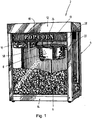
- popcorn machine 2 includes as most machines for the production of popcorn from corn kernels, fat and possibly other ingredients a cuboid housing 4, enclosed by a housing 4 lit and heated warming room 6 with a bottom of the holding space 6 forming drip pan (not visible) to Picking up the finished popcorn, a housed in the interior of the warming room 6 heated container 8, in which the corn kernels, the fat and any other ingredients to bursting (popping) of corn kernels can be heated, and a motor-driven agitator 10 for stirring the ingredients in the container 8.
- a cuboid housing 4 enclosed by a housing 4 lit and heated warming room 6 with a bottom of the holding space 6 forming drip pan (not visible) to Picking up the finished popcorn
- a housed in the interior of the warming room 6 heated container 8 in which the corn kernels, the fat and any other ingredients to bursting (popping) of corn kernels can be heated
- a motor-driven agitator 10 for stirring the ingredients in the container 8.
- the housing 4 consists essentially of four side walls which surround the warming space 6 laterally and are completely or partially glazed, wherein at least one of the side walls for removing popcorn from the warming room 6 and the drip pan can be opened, one above the warming space 6 arranged , the ceiling of the holding space 6 forming housing upper part 12 and one below the Drip tray or the holding space 6 arranged lower housing part 14th
- the heatable cup-shaped container 8 is pivotally suspended in the upper part of the Warmhalteraums 6, wherein it is connected at one side by a support arm 16 with a pivot joint 18 with a horizontal pivot axis 20 hinged to the upper housing part 12, while at the diametrically opposite Side of a support arm (not visible) is releasably held.
- a lock 22 is provided, with which the container 8 in a in Fig. 1 shown horizontal working position can be held in a closed by a cover 24 opening of the container 8 facing upward.
- the lock can be unlocked by means of an unlocking lever 26 to pivot the container 8 about the pivot axis 20 in an emptying position in which the opening of the container 8 obliquely downward, so that in the container. 8 contained popcorn can be emptied into the drip tray of the warming room 6.
- the lid 24 of the container 8 is provided in the middle with an opening through which a drive shaft 28 of the agitator 10 extends.
- the upper end of the drive shaft 28 is connected to a drive motor (not visible) in the upper housing part 12, while the free lower end of the drive shaft 28 with agitator combs or wings (not visible) is fitted.
- the agitator combs or wings protrude in the horizontal working position of the container 8 from the top into the container interior, so that the corn grains in the container 8 can be moved during heating to provide a uniform heating.
- the lid 24 rests loosely on an upper edge of the container 8 so that it can be lifted by the popcorn in the container 8 as soon as the volume of the container contents exceeds the volume of the container 8 as a result of the increase in volume when the corn kernels burst.
- the lid 24 of the Drive shaft retained so that the remaining popcorn may fall through the opening of the container 8.
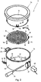
- the popcorn machine 2 For heating the container 8, the popcorn machine 2 has an induction heater, which has a stationary located in the upper housing part 12 frequency converter (not visible) and a pivotable together with the container 8 induction winding 30 (FIG. Fig. 2 ), which is connected by leads 32 to the frequency converter.
- the container 8 essentially consists of a lower pot-shaped outer container 34, a somewhat flatter cup-shaped inner container 36, and the flat induction coil 30 mounted on a support 38, which is arranged in a space between a flat circular bottom 42 of the outer container 34 and one above planar circular bottom 40 of the inner container 36 and aligned parallel to the two bottoms 40, 42 is aligned.
- a temperature sensor 44 for measuring the temperature of the bottom 40 is also attached.
- the induction coil 30 comprises a spirally wound conductor 46 of a twisted copper wire strand disposed in a winding plane on top of the support 38 and coated with a heat-resistant insulating varnish.
- the carrier 38 consists of a flat disc 48 made of a heat-resistant plastic, which is provided for cooling the spiral conductor 46 with a plurality of openings 50.
- the disc 48 is provided for attachment to the inner container 36 with four radially projecting pierced fastening tabs 52. Through the holes adjusting screws 54 can be screwed from below into threaded holes 56 in projections 58 of the inner container 36 to attach the induction coil 30 at a desired distance from the bottom 40 of the inner container 36.
- radially aligned elongate flux conductors 52 are disposed of an electrically nonconducting ferrite material having a high permeability number, which bundle the magnetic field lines on the underside of the carrier 38 between the outer periphery and the center of the carrier 38 and prevent the magnetic field from extending beyond the underside of the disc 48 ,
- the conductor 46 extends from the outer or inner end of the induction winding 30 arranged on the outer circumference of the carrier 38 and / or in the middle thereof through bores 54, 56 of the carrier 38 into a space between the carrier 38 and the bottom 42 of the carrier 38 Outer container 34, where the ends of the conductor 46 are connected to the leads 32.
- the leads 32 are also made of twisted copper wire and have the same cross-section as the conductor 36. They extend through a flexible tube 58 from the outer container 34 to the upper housing part 12, in which their ends are connected to terminals of the frequency converter. In order to prevent heating of the tube 58 by the alternating magnetic field generated around the leads 32, the leads 32 extend in close proximity to each other through the tube 58, so that the two alternating magnetic fields substantially cancel each other out.
- the tube 58 either consists of a non-conductive temperature-resistant plastic material or alternatively of a non-magnetic stainless steel.
- the outer container 34 includes a cylindrical wall portion 60 to which are secured near the upper edge portions of the pivot joint 18 and the locking device 22 and the release lever 26 so that the latter can be grasped by the user to unlock the container 8 and during to keep the pivoting.
- the bottom 42 fixed to the lower end face of the wall part 60 is made of a non-conductive, para or diamagnetic material, for example ceramic or a temperature-resistant plastic material, such as polycarbonate.
- ventilation openings 62 in the Floor 42 and in the lower edge of the wall portion 60 are ventilation openings 62, so that the radiated from the heated bottom 40 of the inner container 36 downward heat can be dissipated by the air circulation in the space from this.
- the inner container 36 and in particular the bottom 40 of the inner container 36 is made of magnetic stainless steel or other ferromagnetic metal with high permeability.
- the bottom 40 can be arranged at a desired distance between about 20 to 30 mm above the induction coil 30. Although this distance ensures that the bottom 40 on the one hand projects far into the alternating magnetic field generated by the induction coil 30, on the other hand, overheating of the induction coil 30 is avoided by the heat radiated downward from the bottom 40 when the container 8 is heated.
- the temperature sensor 44 is a contact sensor designed as an eyelet, which is fastened by means of a nut (not shown) to a screw 64 protruding beyond the underside of the bottom 40.
- the lower housing part 14 of the popcorn machine 2 in Fig. 1 may contain one or more heating elements (not shown) serving for heating the warming room 6 resistance heating, while the upper part 12 in addition to the drive motor for the agitator 10 connectable to the AC power supply (not visible), the frequency converter for reshaping the frequency of the alternating current the power grid in a frequency of about 50 to 60 kHz, and a control unit (not visible) for controlling the induction heating by turning on and off the power supply to the induction coil 30 encloses.
- the AC power supply not visible
- the frequency converter for reshaping the frequency of the alternating current the power grid in a frequency of about 50 to 60 kHz
- a control unit not visible
- the control unit serves to supply power to the induction coil 30 from the frequency converter when the popcorn machine 2 for producing popcorn is turned on by operating a switch on a control panel (not visible) located at the rear of the housing top 12 after a batch of corn kernels and fat in the inner container 36 has been filled.
- the frequency converter After switching on, the frequency converter generates alternating current with a frequency of 50 to 60 kHz, which is supplied through the leads 32 to the induction coil 30, whereby the induction coil 30 generates an alternating magnetic field with the same frequency.
- the alternating magnetic field induces eddy currents in the bottom 40 of the inner container 36, whereby it heats up very quickly, especially since it has only a relatively small material thickness of less than 2 to 3 mm.
- the temperature sensor 44 When the temperature of the bottom 40 rises above a predetermined upper threshold of over 250 ° C, preferably about 210 ° C to 220 ° C, and this temperature rise is detected by the temperature sensor 44 and communicated to the controller, it shuts off power to the induction coil 30 in a short time until the temperature of the bottom 40 has dropped below a lower threshold of below 150 ° C, preferably about 180 ° C to 190 ° C again. In this temperature range of the bottom 40, the production of popcorn in the container 8 optimal, because then the corn kernels are heated neither too slow nor too fast.
- the temperature sensor 44 is connected to the control unit via signal lines 66 which extend together with the leads 32 through the tube 58.
- a switch 68 is attached to the support arm of the housing 4 in the vicinity of the attached to the wall portion 60 of the outer container 34 portion of the lock 22.
- the switch 68 may be formed, for example, as a contact, magnetic or proximity switch and interrupts the power supply to the induction coil 30 when the release lever 26 is operated by the user to unlock the latch 22 for pivoting the container. This ensures that the induction winding 30 is supplied only when the container 8 in his in Fig. 1 shown working position.
- the switch 68 is connected to the controller so that only after a renewed actuation of the switch on the control panel, a renewed power supply to the induction coil 30 is possible.
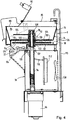
- the pivotable container 8 is not suspended from the housing top 12 as in the previously described popcorn machine 2. As in Fig. 4 instead, the container 8 is supported by a support base 70, which via a collecting trough (in Fig. 4 not shown) the popcorn machine survives.
- the container 8 is pivotable about a horizontal pivot axis 72 arranged below the container 8 and laterally of the support base 70.
- the container 8 also consists of an inner and an outer container 74 and 76, which are separated by a gap 78 from each other.
- the inner container 76 has like the inner container 36 in Fig. 2 a thin bottom 80 of ferromagnetic metal of high permeability, while the bottom 82 of the outer container 76 is made of a heat-resistant non-conductive dia- or paramagnetic material.
- the container 8 Up to the container 8 is closed by a fixed cover 84.
- the container 8 has on one side a slightly below the lid 84 located outlet 86 which is closed by a hinged flap 88.
- the flap 88 is held in place by counterweights 90 until it is pivoted upwardly into an open position by the pressure of the popcorn formed in the container 8 when the container 8 is completely filled with popcorn. A portion of the popcorn can then exit through the spout 86 into the drip pan, which, like the popcorn machine in Fig. 1 can be arranged in a warm storage room.
- the stirrer 92 of in Fig. 3 illustrated container 8 comprises a below the container 8 in the support base 70 arranged drive motor 94 and a two-part drive shaft whose vertical lower part 96 is rotatably mounted in the support base 70, while the upper part 98 in a the floors 80, 82 of the container 8 passing through bushing 100th stored and can be pivoted together with the container 8.
- the two parts 96, 98 are connected at 102 by a coupling which is automatically switched on and disengaged during pivoting of the container 8.
- Agitator 92 includes a plurality of radial agitator combs or vanes 104 that protrude near bottom 80 of inner container 74 and at a greater distance from bottom 80 via a rotatable cap 106.
- the cap 106 is connected by a splint 108 with the upper part 98 of the drive shaft and surrounds the projecting into the container 8 bushing 100th
- the fat required for the production of popcorn is fed here in liquid form through a grease supply tube 110 into the container 8.
- the induction heater comprises a frequency converter 112 housed inside the support base 70 and connected to a power supply unit (not shown) and one on a support 114 in the gap 78 between the floors 80, 82 of the indoor and outdoor units Outer container 74, 76 arranged and pivotable together with the container 8 pivotable induction winding 116.
- the frequency converter 102 is connected by leads 118 to the induction coil 116, which after exiting the support base 70 through a flexible tube 120 to the outside of the outer container 76 and from there into the gap 78.
- the induction coil 116 and the carrier 114 have substantially the same configuration as those in FIG Fig. 2 except that the carrier 114 and the induction coil 116 surround a central opening.
- a retaining ring 122 is attached to the carrier, which is pushed at a distance below the bottom 80 of the inner container 74 on the bearing bushing 100 and rotatably connected to the bearing bush 100, so that the rotatable upper part 98 of the drive shaft in the bearing bush 100th extends axially through the carrier 114 and the induction coil 116 therethrough.
- the retaining ring 122 may be made of a ferrite material, such as flux guides 124 on the underside of the carrier 114, thereby preventing the field lines of the alternating magnetic field from extending to the bushing 100 and the drive shaft to heat the bushing 100 and the upper portion 98 of the drive shaft to prevent.
- the bushing 100 and the upper portion 98 of the drive shaft may also be made of a non-conductive diamagnetic or paramagnetic material, such as a plastic material, so that they do not heat up in an alternating magnetic field passing through the aperture.
- a fan 124 is arranged in the intermediate space 78, the air sucks from below through an opening in the gap 78 and against the underside of the carrier 114 blows. from there the air then flows along the underside of the carrier 114 to ventilation openings 126 on the opposite side of the Outer container 76.
- the temperature of the bottom 80 is measured by means of a temperature sensor (not shown) and the current supplied to the induction winding 116 is controlled in dependence on the measured temperature.
- the power supply is also turned off.
Landscapes
- Physics & Mathematics (AREA)
- Electromagnetism (AREA)
- Engineering & Computer Science (AREA)
- Food Science & Technology (AREA)
- Grain Derivatives (AREA)
- General Induction Heating (AREA)
- Baking, Grill, Roasting (AREA)
- Package Specialized In Special Use (AREA)
Priority Applications (1)
| Application Number | Priority Date | Filing Date | Title |
|---|---|---|---|
| PL08758705T PL2154993T3 (pl) | 2007-05-29 | 2008-05-23 | Maszyna do popcornu z podgrzewaniem indukcyjnym |
Applications Claiming Priority (2)
| Application Number | Priority Date | Filing Date | Title |
|---|---|---|---|
| DE102007025026A DE102007025026A1 (de) | 2007-05-29 | 2007-05-29 | Popcornmaschine mit Induktionsheizung |
| PCT/EP2008/004106 WO2008145303A1 (de) | 2007-05-29 | 2008-05-23 | Popcornmaschine mit induktionsheizung |
Publications (2)
| Publication Number | Publication Date |
|---|---|
| EP2154993A1 EP2154993A1 (de) | 2010-02-24 |
| EP2154993B1 true EP2154993B1 (de) | 2012-05-02 |
Family
ID=39768838
Family Applications (1)
| Application Number | Title | Priority Date | Filing Date |
|---|---|---|---|
| EP08758705A Active EP2154993B1 (de) | 2007-05-29 | 2008-05-23 | Popcornmaschine mit induktionsheizung |
Country Status (9)
| Country | Link |
|---|---|
| US (1) | US20080295701A1 (pl) |
| EP (1) | EP2154993B1 (pl) |
| AT (1) | ATE555669T1 (pl) |
| CA (1) | CA2687733C (pl) |
| DE (1) | DE102007025026A1 (pl) |
| PL (1) | PL2154993T3 (pl) |
| RU (1) | RU2470524C2 (pl) |
| UA (1) | UA96992C2 (pl) |
| WO (1) | WO2008145303A1 (pl) |
Cited By (1)
| Publication number | Priority date | Publication date | Assignee | Title |
|---|---|---|---|---|
| WO2019169391A1 (en) * | 2018-03-02 | 2019-09-06 | Kenyon Technologies, Llc | Controller for popcorn popper |
Families Citing this family (13)
| Publication number | Priority date | Publication date | Assignee | Title |
|---|---|---|---|---|
| JP5404917B2 (ja) * | 2009-05-06 | 2014-02-05 | ガストロ アーゲー | 料理を保温する誘導加熱用食器 |
| US9084504B2 (en) | 2011-11-01 | 2015-07-21 | Kenyon International, Inc. | Vibrating cooking system |
| DE102012104434A1 (de) * | 2012-05-23 | 2013-11-28 | Hella Kgaa Hueck & Co. | Verfahren für die Bestimmung des Ladestandes eines Energiespeichers |
| US9796056B2 (en) * | 2013-03-08 | 2017-10-24 | Gold Medal Products Company | Popcorn popping kettle and stud retainer assembly |
| USD745309S1 (en) | 2013-12-03 | 2015-12-15 | 8479950 Canada Inc. | Food dispenser |
| UA89863U (uk) * | 2014-02-24 | 2014-04-25 | Геннадий Анатольевич Крылатый | Апарат з індукційним нагріванням для виготовлення попкорну "крилатий попкорн" |
| USD760020S1 (en) | 2014-07-07 | 2016-06-28 | 8479950 Canada Inc. | Food station |
| US10349668B2 (en) * | 2015-06-25 | 2019-07-16 | Kenyon Technologies, Llc | Popcorn maker |
| US10342330B2 (en) | 2016-07-26 | 2019-07-09 | Trademark Global, LLC | Collapsible and shippable base assembly such as incorporated into a popcorn cart including a lower wheeled support frame and an upper popcorn kernal popper assembly and cabinet and including a kit incorporating such a collapsible and shippable base assembly |
| JP6749211B2 (ja) * | 2016-10-26 | 2020-09-02 | 三菱電機株式会社 | 誘導加熱調理器 |
| US11665790B2 (en) * | 2016-12-22 | 2023-05-30 | Whirlpool Corporation | Induction burner element having a plurality of single piece frames |
| US20250017408A1 (en) * | 2021-11-17 | 2025-01-16 | Zhuhai Unicook Technology Co., Ltd. | Cooking Device |
| US20250040744A1 (en) * | 2023-08-03 | 2025-02-06 | C. Cretors & Company | Inductively heated kettle |
Family Cites Families (13)
| Publication number | Priority date | Publication date | Assignee | Title |
|---|---|---|---|---|
| US2134682A (en) * | 1936-07-25 | 1938-11-01 | Julian R Burch | Popcorn machine |
| US2112358A (en) * | 1937-07-19 | 1938-03-29 | Charles J Cretors | Corn popping machine |
| US2654823A (en) * | 1948-09-15 | 1953-10-06 | Hercules Steel Products Corp | Popcorn machine |
| US2907264A (en) * | 1956-12-27 | 1959-10-06 | George H Bushway | Corn popping machine |
| US5555792A (en) * | 1994-10-24 | 1996-09-17 | Six Corners Development Company | Corn popping kettle assembly |
| FR2748885B1 (fr) * | 1996-05-14 | 1998-08-14 | Europ Equip Menager | Foyer de cuisson par induction a rendement eleve |
| US5928550A (en) | 1997-04-18 | 1999-07-27 | Gold Medal Products Co. | Popcorn popper with induction heating |
| DE10122337B4 (de) * | 2001-05-08 | 2006-04-13 | Schott Ag | Wasserkocher aus Glas mit induktiver Heizung |
| WO2003053104A1 (en) * | 2001-12-14 | 2003-06-26 | Clad Metals Llc | Food cooking or warming apparatus with self-regulating inductor |
| US6752071B1 (en) * | 2002-02-15 | 2004-06-22 | Gold Medal Products Company | Thick film heater for a popcorn popper |
| FR2845570B1 (fr) * | 2002-10-09 | 2005-07-15 | Francois Berthault | Dispositif de presentation et de cuisson notamment de grains de mais pour la fabrication de pop corn |
| US7022952B2 (en) * | 2003-08-26 | 2006-04-04 | General Electric Company | Dual coil induction heating system |
| US20060042472A1 (en) * | 2004-08-24 | 2006-03-02 | Shore Angela M | Popcorn popper |
-
2007
- 2007-05-29 DE DE102007025026A patent/DE102007025026A1/de not_active Withdrawn
-
2008
- 2008-05-23 UA UAA200913025A patent/UA96992C2/ru unknown
- 2008-05-23 AT AT08758705T patent/ATE555669T1/de active
- 2008-05-23 EP EP08758705A patent/EP2154993B1/de active Active
- 2008-05-23 WO PCT/EP2008/004106 patent/WO2008145303A1/de not_active Ceased
- 2008-05-23 PL PL08758705T patent/PL2154993T3/pl unknown
- 2008-05-23 CA CA2687733A patent/CA2687733C/en active Active
- 2008-05-23 RU RU2009148596/10A patent/RU2470524C2/ru active
- 2008-05-28 US US12/128,244 patent/US20080295701A1/en not_active Abandoned
Cited By (1)
| Publication number | Priority date | Publication date | Assignee | Title |
|---|---|---|---|---|
| WO2019169391A1 (en) * | 2018-03-02 | 2019-09-06 | Kenyon Technologies, Llc | Controller for popcorn popper |
Also Published As
| Publication number | Publication date |
|---|---|
| EP2154993A1 (de) | 2010-02-24 |
| WO2008145303A1 (de) | 2008-12-04 |
| ATE555669T1 (de) | 2012-05-15 |
| CA2687733C (en) | 2016-01-12 |
| PL2154993T3 (pl) | 2012-10-31 |
| UA96992C2 (ru) | 2011-12-26 |
| US20080295701A1 (en) | 2008-12-04 |
| CA2687733A1 (en) | 2008-12-04 |
| DE102007025026A1 (de) | 2008-12-11 |
| RU2470524C2 (ru) | 2012-12-27 |
| RU2009148596A (ru) | 2011-07-10 |
Similar Documents
| Publication | Publication Date | Title |
|---|---|---|
| EP2154993B1 (de) | Popcornmaschine mit induktionsheizung | |
| EP2227118B1 (de) | Automatischer milchschaumbereiter | |
| DE202018006407U1 (de) | Kochgerät und Komponenten davon | |
| DE19908443A1 (de) | Induktionsheizvorrichtung | |
| DE68908271T2 (de) | Haushaltskochgerät. | |
| DE202011050875U1 (de) | Küchenmaschine mit einem Rührgefäß | |
| DE69704889T2 (de) | Elektrisches Widerstandselement für Bodenheizung, insbesonderes für Wasserkochgeräte | |
| DE1579508A1 (de) | Geheiztes Tellerausgabegeraet | |
| DE3308732A1 (de) | Hochfrequnezheizgeraet mit einer rotierenden antenne | |
| WO2021214176A2 (de) | KOCHFELD SOWIE ZUBEREITUNGSGEFÄß FÜR NAHRUNGSMITTEL UND DIESE UMFASSENEDE ZUBEREITUNGSVORRICHTUNG | |
| DE69516458T2 (de) | Verfahren zum Steueren eines Mikrowellenofens, Mikrowellenofen und seine Verwendung zum Kochen oder Erwarmen eines Nahrungmittels nach diesem Verfahren | |
| DE10065215A1 (de) | Gargerät | |
| DE2623946C3 (de) | Umluft-Wärme-, -Back- und -Bratgerät | |
| DE3006679C2 (de) | Gerät zum elektrischen Beheizen von Rundkolben aus Glas o.dgl. | |
| EP1844688B1 (de) | Koch-, Gar-und/oder Warmhaltegerät, insbesondere Tischkochgerät | |
| DE202023106529U1 (de) | Handgeführte Vorrichtung zum Überbacken von Lebensmittelprodukten | |
| EP0626148B1 (de) | Heizbarer Milchbehälter | |
| DE602006000137T2 (de) | Küchenmaschine | |
| EP2574901B1 (de) | Messgerät zur gravimetrischen Feuchtigkeitsbestimmung | |
| EP4401995B1 (de) | Befüllvorrichtung für eine klimaanlage | |
| CH704207A2 (de) | Dynamisches Kochfeld. | |
| DE102014110186B4 (de) | Vorrichtung zur Wärmebehandlung von Lebensmitteln | |
| EP2741576B1 (de) | Mikrowellengerät | |
| DE102005011547B4 (de) | Elektrischer Saunaofen | |
| DE102016115240B4 (de) | Garvorrichtung zum Garen und Gareinheit mit einer Garvorrichtung |
Legal Events
| Date | Code | Title | Description |
|---|---|---|---|
| PUAI | Public reference made under article 153(3) epc to a published international application that has entered the european phase |
Free format text: ORIGINAL CODE: 0009012 |
|
| 17P | Request for examination filed |
Effective date: 20091019 |
|
| AK | Designated contracting states |
Kind code of ref document: A1 Designated state(s): AT BE BG CH CY CZ DE DK EE ES FI FR GB GR HR HU IE IS IT LI LT LU LV MC MT NL NO PL PT RO SE SI SK TR |
|
| AX | Request for extension of the european patent |
Extension state: AL BA MK RS |
|
| DAX | Request for extension of the european patent (deleted) | ||
| GRAP | Despatch of communication of intention to grant a patent |
Free format text: ORIGINAL CODE: EPIDOSNIGR1 |
|
| GRAS | Grant fee paid |
Free format text: ORIGINAL CODE: EPIDOSNIGR3 |
|
| GRAA | (expected) grant |
Free format text: ORIGINAL CODE: 0009210 |
|
| AK | Designated contracting states |
Kind code of ref document: B1 Designated state(s): AT BE BG CH CY CZ DE DK EE ES FI FR GB GR HR HU IE IS IT LI LT LU LV MC MT NL NO PL PT RO SE SI SK TR |
|
| REG | Reference to a national code |
Ref country code: GB Ref legal event code: FG4D Free format text: NOT ENGLISH |
|
| REG | Reference to a national code |
Ref country code: AT Ref legal event code: REF Ref document number: 555669 Country of ref document: AT Kind code of ref document: T Effective date: 20120515 Ref country code: CH Ref legal event code: EP |
|
| REG | Reference to a national code |
Ref country code: IE Ref legal event code: FG4D Free format text: LANGUAGE OF EP DOCUMENT: GERMAN |
|
| REG | Reference to a national code |
Ref country code: DE Ref legal event code: R096 Ref document number: 502008007137 Country of ref document: DE Effective date: 20120628 |
|
| REG | Reference to a national code |
Ref country code: NL Ref legal event code: T3 |
|
| REG | Reference to a national code |
Ref country code: SE Ref legal event code: TRGR |
|
| REG | Reference to a national code |
Ref country code: LT Ref legal event code: MG4D Effective date: 20120502 |
|
| PG25 | Lapsed in a contracting state [announced via postgrant information from national office to epo] |
Ref country code: CY Free format text: LAPSE BECAUSE OF FAILURE TO SUBMIT A TRANSLATION OF THE DESCRIPTION OR TO PAY THE FEE WITHIN THE PRESCRIBED TIME-LIMIT Effective date: 20120502 Ref country code: NO Free format text: LAPSE BECAUSE OF FAILURE TO SUBMIT A TRANSLATION OF THE DESCRIPTION OR TO PAY THE FEE WITHIN THE PRESCRIBED TIME-LIMIT Effective date: 20120802 Ref country code: LT Free format text: LAPSE BECAUSE OF FAILURE TO SUBMIT A TRANSLATION OF THE DESCRIPTION OR TO PAY THE FEE WITHIN THE PRESCRIBED TIME-LIMIT Effective date: 20120502 Ref country code: IS Free format text: LAPSE BECAUSE OF FAILURE TO SUBMIT A TRANSLATION OF THE DESCRIPTION OR TO PAY THE FEE WITHIN THE PRESCRIBED TIME-LIMIT Effective date: 20120902 Ref country code: FI Free format text: LAPSE BECAUSE OF FAILURE TO SUBMIT A TRANSLATION OF THE DESCRIPTION OR TO PAY THE FEE WITHIN THE PRESCRIBED TIME-LIMIT Effective date: 20120502 |
|
| REG | Reference to a national code |
Ref country code: PL Ref legal event code: T3 |
|
| PG25 | Lapsed in a contracting state [announced via postgrant information from national office to epo] |
Ref country code: HR Free format text: LAPSE BECAUSE OF FAILURE TO SUBMIT A TRANSLATION OF THE DESCRIPTION OR TO PAY THE FEE WITHIN THE PRESCRIBED TIME-LIMIT Effective date: 20120502 Ref country code: GR Free format text: LAPSE BECAUSE OF FAILURE TO SUBMIT A TRANSLATION OF THE DESCRIPTION OR TO PAY THE FEE WITHIN THE PRESCRIBED TIME-LIMIT Effective date: 20120803 Ref country code: PT Free format text: LAPSE BECAUSE OF FAILURE TO SUBMIT A TRANSLATION OF THE DESCRIPTION OR TO PAY THE FEE WITHIN THE PRESCRIBED TIME-LIMIT Effective date: 20120903 Ref country code: LV Free format text: LAPSE BECAUSE OF FAILURE TO SUBMIT A TRANSLATION OF THE DESCRIPTION OR TO PAY THE FEE WITHIN THE PRESCRIBED TIME-LIMIT Effective date: 20120502 Ref country code: SI Free format text: LAPSE BECAUSE OF FAILURE TO SUBMIT A TRANSLATION OF THE DESCRIPTION OR TO PAY THE FEE WITHIN THE PRESCRIBED TIME-LIMIT Effective date: 20120502 |
|
| PG25 | Lapsed in a contracting state [announced via postgrant information from national office to epo] |
Ref country code: MC Free format text: LAPSE BECAUSE OF NON-PAYMENT OF DUE FEES Effective date: 20120531 |
|
| PG25 | Lapsed in a contracting state [announced via postgrant information from national office to epo] |
Ref country code: SK Free format text: LAPSE BECAUSE OF FAILURE TO SUBMIT A TRANSLATION OF THE DESCRIPTION OR TO PAY THE FEE WITHIN THE PRESCRIBED TIME-LIMIT Effective date: 20120502 Ref country code: RO Free format text: LAPSE BECAUSE OF FAILURE TO SUBMIT A TRANSLATION OF THE DESCRIPTION OR TO PAY THE FEE WITHIN THE PRESCRIBED TIME-LIMIT Effective date: 20120502 Ref country code: CZ Free format text: LAPSE BECAUSE OF FAILURE TO SUBMIT A TRANSLATION OF THE DESCRIPTION OR TO PAY THE FEE WITHIN THE PRESCRIBED TIME-LIMIT Effective date: 20120502 Ref country code: DK Free format text: LAPSE BECAUSE OF FAILURE TO SUBMIT A TRANSLATION OF THE DESCRIPTION OR TO PAY THE FEE WITHIN THE PRESCRIBED TIME-LIMIT Effective date: 20120502 Ref country code: EE Free format text: LAPSE BECAUSE OF FAILURE TO SUBMIT A TRANSLATION OF THE DESCRIPTION OR TO PAY THE FEE WITHIN THE PRESCRIBED TIME-LIMIT Effective date: 20120502 |
|
| REG | Reference to a national code |
Ref country code: IE Ref legal event code: MM4A |
|
| PLBE | No opposition filed within time limit |
Free format text: ORIGINAL CODE: 0009261 |
|
| STAA | Information on the status of an ep patent application or granted ep patent |
Free format text: STATUS: NO OPPOSITION FILED WITHIN TIME LIMIT |
|
| 26N | No opposition filed |
Effective date: 20130205 |
|
| PG25 | Lapsed in a contracting state [announced via postgrant information from national office to epo] |
Ref country code: IE Free format text: LAPSE BECAUSE OF NON-PAYMENT OF DUE FEES Effective date: 20120523 Ref country code: ES Free format text: LAPSE BECAUSE OF FAILURE TO SUBMIT A TRANSLATION OF THE DESCRIPTION OR TO PAY THE FEE WITHIN THE PRESCRIBED TIME-LIMIT Effective date: 20120813 |
|
| REG | Reference to a national code |
Ref country code: DE Ref legal event code: R097 Ref document number: 502008007137 Country of ref document: DE Effective date: 20130205 |
|
| PG25 | Lapsed in a contracting state [announced via postgrant information from national office to epo] |
Ref country code: MT Free format text: LAPSE BECAUSE OF FAILURE TO SUBMIT A TRANSLATION OF THE DESCRIPTION OR TO PAY THE FEE WITHIN THE PRESCRIBED TIME-LIMIT Effective date: 20120502 Ref country code: BG Free format text: LAPSE BECAUSE OF FAILURE TO SUBMIT A TRANSLATION OF THE DESCRIPTION OR TO PAY THE FEE WITHIN THE PRESCRIBED TIME-LIMIT Effective date: 20120802 |
|
| PG25 | Lapsed in a contracting state [announced via postgrant information from national office to epo] |
Ref country code: LU Free format text: LAPSE BECAUSE OF NON-PAYMENT OF DUE FEES Effective date: 20120523 |
|
| PG25 | Lapsed in a contracting state [announced via postgrant information from national office to epo] |
Ref country code: HU Free format text: LAPSE BECAUSE OF FAILURE TO SUBMIT A TRANSLATION OF THE DESCRIPTION OR TO PAY THE FEE WITHIN THE PRESCRIBED TIME-LIMIT Effective date: 20080523 |
|
| REG | Reference to a national code |
Ref country code: FR Ref legal event code: PLFP Year of fee payment: 9 |
|
| REG | Reference to a national code |
Ref country code: FR Ref legal event code: PLFP Year of fee payment: 10 |
|
| REG | Reference to a national code |
Ref country code: FR Ref legal event code: PLFP Year of fee payment: 11 |
|
| REG | Reference to a national code |
Ref country code: DE Ref legal event code: R082 Ref document number: 502008007137 Country of ref document: DE Representative=s name: WEIDNER STERN JESCHKE PATENTANWAELTE PARTNERSC, DE |
|
| P02 | Opt-out of the competence of the unified patent court (upc) changed |
Effective date: 20230526 |
|
| PGFP | Annual fee paid to national office [announced via postgrant information from national office to epo] |
Ref country code: SE Payment date: 20250311 Year of fee payment: 18 |
|
| PGFP | Annual fee paid to national office [announced via postgrant information from national office to epo] |
Ref country code: NL Payment date: 20250522 Year of fee payment: 18 |
|
| PGFP | Annual fee paid to national office [announced via postgrant information from national office to epo] |
Ref country code: PL Payment date: 20250512 Year of fee payment: 18 Ref country code: DE Payment date: 20250131 Year of fee payment: 18 |
|
| PGFP | Annual fee paid to national office [announced via postgrant information from national office to epo] |
Ref country code: GB Payment date: 20250522 Year of fee payment: 18 |
|
| PGFP | Annual fee paid to national office [announced via postgrant information from national office to epo] |
Ref country code: IT Payment date: 20250530 Year of fee payment: 18 Ref country code: BE Payment date: 20250520 Year of fee payment: 18 |
|
| PGFP | Annual fee paid to national office [announced via postgrant information from national office to epo] |
Ref country code: FR Payment date: 20250523 Year of fee payment: 18 |
|
| PGFP | Annual fee paid to national office [announced via postgrant information from national office to epo] |
Ref country code: CH Payment date: 20250601 Year of fee payment: 18 |
|
| PGFP | Annual fee paid to national office [announced via postgrant information from national office to epo] |
Ref country code: AT Payment date: 20250519 Year of fee payment: 18 |
|
| PGFP | Annual fee paid to national office [announced via postgrant information from national office to epo] |
Ref country code: TR Payment date: 20250515 Year of fee payment: 18 |