EP2154707A2 - Filament lamp - Google Patents
Filament lamp Download PDFInfo
- Publication number
- EP2154707A2 EP2154707A2 EP09166453A EP09166453A EP2154707A2 EP 2154707 A2 EP2154707 A2 EP 2154707A2 EP 09166453 A EP09166453 A EP 09166453A EP 09166453 A EP09166453 A EP 09166453A EP 2154707 A2 EP2154707 A2 EP 2154707A2
- Authority
- EP
- European Patent Office
- Prior art keywords
- sealing section
- light emitting
- filaments
- section
- filament lamp
- Prior art date
- Legal status (The legal status is an assumption and is not a legal conclusion. Google has not performed a legal analysis and makes no representation as to the accuracy of the status listed.)
- Withdrawn
Links
Images


Classifications
-
- H—ELECTRICITY
- H01—ELECTRIC ELEMENTS
- H01K—ELECTRIC INCANDESCENT LAMPS
- H01K9/00—Lamps having two or more incandescent bodies separately heated
- H01K9/08—Lamps having two or more incandescent bodies separately heated to provide selectively different light effects, e.g. for automobile headlamp
-
- H—ELECTRICITY
- H01—ELECTRIC ELEMENTS
- H01K—ELECTRIC INCANDESCENT LAMPS
- H01K3/00—Apparatus or processes adapted to the manufacture, installing, removal, or maintenance of incandescent lamps or parts thereof
-
- H—ELECTRICITY
- H01—ELECTRIC ELEMENTS
- H01K—ELECTRIC INCANDESCENT LAMPS
- H01K1/00—Details
- H01K1/40—Leading-in conductors
-
- H—ELECTRICITY
- H01—ELECTRIC ELEMENTS
- H01K—ELECTRIC INCANDESCENT LAMPS
- H01K1/00—Details
- H01K1/42—Means forming part of the lamp for the purpose of providing electrical connection, or support for, the lamp
- H01K1/44—Means forming part of the lamp for the purpose of providing electrical connection, or support for, the lamp directly applied to, or forming part of, the vessel
-
- H—ELECTRICITY
- H01—ELECTRIC ELEMENTS
- H01K—ELECTRIC INCANDESCENT LAMPS
- H01K7/00—Lamps for purposes other than general lighting
-
- H—ELECTRICITY
- H05—ELECTRIC TECHNIQUES NOT OTHERWISE PROVIDED FOR
- H05B—ELECTRIC HEATING; ELECTRIC LIGHT SOURCES NOT OTHERWISE PROVIDED FOR; CIRCUIT ARRANGEMENTS FOR ELECTRIC LIGHT SOURCES, IN GENERAL
- H05B3/00—Ohmic-resistance heating
- H05B3/0033—Heating devices using lamps
- H05B3/0038—Heating devices using lamps for industrial applications
- H05B3/0047—Heating devices using lamps for industrial applications for semiconductor manufacture
Definitions
- Devices and apparatuses consistent with the present invention relate to filament lamps, and, in particular, to filament lamps used for heating an object to be treated.
- a thermal diffusion process for diffusing P-type semiconductors there are a thermal diffusion process for diffusing P-type semiconductors and a firing process for firing silver paste that is used as an electrode material.
- a semiconductor wafer or a glass substrate is heated to a high temperature, for example, 800 to 900°C by using a thermal diffusion furnace and a firing furnace.
- this heat treatment device should uniformly heat the object to be treated to prevent difference in temperature according to location.
- a filament lamp that is used as a light source, has a plurality of power supply paths in an arc tube, and can independently supply desired electric power to respective paths (see e.g., JP-A-2006-279008 ). Further, since such a filament lamp has a plurality of power supply paths in the arc tube, terminals whose number corresponds to the number of the power supply paths should be provided to sealing sections of the lamp.
- Exemplary embodiments of the present invention address the above disadvantages and other disadvantages not described above.
- the present invention is not required to overcome the disadvantages described above, and thus, an exemplary embodiment of the present invention may not overcome any of the disadvantages described above.
- a filament lamp includes: a long light emitting section including a plurality of filaments aligned with one another in an axial direction of the light emitting section, wherein electric power is independently supplied to each of the filaments; a sealing section that seals the light emitting section, including: a first sealing section provided at one end of the light emitting section; and a second sealing section provided at the other end of the light emitting section; a plurality of metal foils embedded in the sealing section; a plurality of external leads each connected to a corresponding one of the metal foils and extending from the sealing section to the outside; and a plurality of glass pipes each provided on the sealing section so as to cover a corresponding one of the external leads.
- a heat treatment device including the filament lamp.
- FIG. 1 is a view showing the entire configuration of a filament lamp according to an exemplary embodiment of the invention.
- a lamp L includes a long light emitting section 10, and sealing sections 20 (20a and 20b) that are formed at both ends of the light emitting section 10.
- the lamp L has a tubular shape as a whole.
- An airtight space is formed in the light emitting section 10, and the light emitting section 10 is provided with a plurality of filaments F (F1, F2, and F3) that extends in the axial direction of the light emitting section 10.
- the filaments F1, F2, and F3 are completely electrically isolated from one another.
- the filament F1 is disposed in the middle of the light emitting section 10
- the filament F2 is disposed at one end of the light emitting section 10 (at the end close to the sealing section 20a)
- the filament F3 is disposed at the other end of the light emitting section 10 (at the end close to the sealing section 20b).
- the filaments F1, F2, and F3 are aligned with one another so as to parallel to the central axis of the light emitting section 10.
- Metal foils 30 (31a, 32a, 33a, 31b, 32b, and 33b), which correspond to the number of the filaments F, are embedded in the sealing sections 20 (20a and 20b). Specifically, the metal foil 31a corresponding to the filament F1, the metal foil 32a corresponding to the filament F2, and the metal foil 33a corresponding to the filament F2 are embedded in the sealing section 20a. Further, the metal foil 31 b corresponding to the filament F1, the metal foil 32b corresponding to the filament F3, and the metal foil 33b corresponding to the filament F3 are embedded in the sealing section 20b.
- External leads 40 (41a, 42a, 43a, 41b, 42b, and 43b) extending outside the lamp and internal leads 50 (51a, 52a, 53a, 51b, 52b, and 53b) extending inside the light emitting section 10 are connected to the metal foils 30.
- the external lead 41a and the internal lead 51a are connected to the metal foil 31a
- the external lead 42a and the internal lead 52a are connected to the metal foil 32a
- the external lead 43a and the internal lead 53a are connected to the metal foil 33a.
- the external lead 41 b and the internal lead 51 b are connected to the metal foil 31 b
- the external lead 42b and the internal lead 52b are connected to the metal foil 32b
- the external lead 43b and the internal lead 53b are connected to the metal foil 33b.
- one independent conduction path is formed of the external lead 41 a, the metal foil 31 a, the internal lead 51a, the filament F1, the internal lead 51 b, the metal foil 31 b, and the external lead 41b. Predetermined electric power is supplied to the external lead 41 a and the external lead 41b, so that the filament F1 emits light.
- one independent conduction path is formed of the external lead 42a, the metal foil 32a, the internal lead 52a, the filament F2, the internal lead 53a, the metal foil 33a, and the external lead 43a. Predetermined electric power is supplied to the external lead 42a and the external lead 43b, so that the filament F2 emits light.
- one independent conduction path is formed of the external lead 42b, the metal foil 32b, the internal lead 52b, the filament F3, the internal lead 53b, the metal foil 33b, and the external lead 43b.
- Predetermined electric power is supplied to the external lead 42b and the external lead 43b, so that the filament F3 emits light.
- the external lead 42a and the external lead 43a which correspond to the filament F2 and disposed at one end of the light emitting section 10, are formed so as to protrude from the sealing section 20a that is close to the filament F2, and two external leads 42b and 43b, which correspond to the filament F3 and disposed at the other end of the light emitting section 10, are formed so as to protrude from the sealing section 20b that is close to the filament F3.
- the filament lamp for example, electric power of 3 kW is supplied to the filament F1 disposed in the middle of the light emitting section 10, and electric power of 600 W is supplied to the filaments F2 and F3 disposed at the ends of the light emitting section 10. Meanwhile, the filaments F1, F2, and F3 may be turned on at the same time, but a part of filaments may be turned on and the other filaments may be turned off.
- the filaments F are formed by closely winding, for example, a tungsten wire in the shape of a coil.
- An inert gas such as argon (Ar) or nitrogen (N 2 )
- halogen such as bromine (Br) or chlorine (Cl).
- anchors for supporting the filaments F or the internal leads 50 may be provided.
- the internal leads 50 may be coated with insulating members.
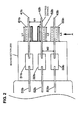
- Fig. 2 is an enlarged view of the sealing section 20b, when seen in the same direction as Fig. 1 .
- Glass pipes 60 (61b, 62b, and 63b) are fixed to the external leads 40 (41b, 42b and 43b), respectively. Since the glass pipes 60 are formed so as to cover the external leads 40 without coming in contact with the outer surfaces of the external leads 40, the creeping distance between adjacent external leads 40 is increased.
- the creeping distance between the external lead 41b and the external lead 42b is substantially equal to the sum of the length twice as long as the length L1 of the external lead 41b (the length of a discontiguous portion) in the glass pipe 61b in the longitudinal direction, the length twice as long as the length L2 of the external lead 42b (the length of a discontiguous portion) in the glass pipe 62b, and the separation distance W1 between the external leads 41b and 42b in the direction orthogonal to the extending direction of each external lead.
- the creeping distance between the external lead 42b and the external lead 43b is substantially equal to the sum of the length twice as long as the length L2 of the external lead 42b (the length of the discontiguous portion) in the glass pipe 62b in a longitudinal direction, the length twice as long as the length L3 of the external lead 43b (the length of the discontiguous portion) in the glass pipe 63b, and the separation distance W2 between the external leads 42b and 43b in the direction orthogonal to the extending direction of each external lead. Accordingly, for example, even though high electric power of 3 kW is supplied to the filament as described above, the creeping distance between the external leads is increased. Therefore, it may be possible to effectively prevent creeping discharge.
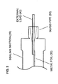
- Fig. 3 is a partially enlarged view of the sealing section 20, when seen in the direction that is indicated by the arrow "A" shown in Fig. 2 .
- the glass pipe 60 is provided so as to correspond to the external lead 40 that protrudes from the end of the sealing section 20. Meanwhile, in Fig. 3 , the metal foil 30, the external lead 40, and the glass pipe 60 are provided side by side in a vertical direction of a plane of paper. The inner surface of the glass pipe 60 is separated from the external lead 40 without coming in contact with the external lead.
- both-ends sealed filament lamp including a long light emitting section (see e.g., JP-A-2001-210280 )
- only one external lead protrudes from one sealing section. Therefore, a problem that creeping discharge occurs between adjacent external leads does not exist.
- one-end sealed filament lamp including only one sealing section (see e.g., Fig. 5 of JP-UM-A-1-161548 )
- two external leads protrude from one sealing section.
- this structure merely corresponds to the external leads that form the same power supply path and the difference in potential is small, the problem the creeping discharge occurs does not exist.
- exemplary embodiments of the invention are particularly applied to a filament lamp where at least three external leads are formed in one sealing section and plural independent power supply paths are formed.
- the end of the glass pipe 60 facing the sealing section 20 is integrally pinched and sealed together with the material that forms the sealing section 20. Accordingly, quartz glass forming the glass pipe 60 and quartz glass forming the sealing section 20 are melted and substantially integrated with each other. That is, if a recess is formed at the sealing section 20 and a glass pipe is inserted into the recess, there is a possibility that creeping discharge occurs in the gap generated between the pipe and the recess. However, since the above-mentioned gap is not formed in the exemplary embodiment of the invention, it may be possible to completely prevent the creeping discharge generated in the gap.
- the length of the sealing section 20 in width is in a range of about 13 mm to about 18 mm, for example, 18 mm.
- the separation distance W between the adjacent external leads 40 is in a range of about 5 mm to about 7 mm, for example, 6 mm.
- the length L of the external lead (the length of a discontiguous portion) covered by the glass pipe 60 in the longitudinal direction (in the axial direction) is in a range of about 5 mm to about 15 mm, for example, 10 mm.
- the outer diameter of the glass pipe 60 is ⁇ 13 mm, and the inner diameter of the glass pipe 60 is ⁇ 10.5 mm. Accordingly, the creeping distance is, for example, 26 mm.
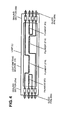
- Fig. 4 is a view showing a filament lamp according to another exemplary embodiment of the invention.
- the filament lamp shown in Fig. 1 includes three filaments to which electric power may be independently supplied, but the filament lamp shown in Fig. 4 includes four filaments. This is the difference between the filament lamps.
- Filaments F11 and F12 are disposed in the middle of a light emitting section 10, a filament F2 is disposed at one end of the light emitting section 10 (at the end close to a sealing section 20a), and a filament F3 is disposed at the other end of the light emitting section 10 (at the end close to a sealing section 20b).
- the filaments F11, F12, F2, and F3 are aligned with one another so as to be parallel to the central axis of the light emitting section 10. Even in the case of the filament lamp having the above-mentioned structure, glass pipes having the structure as shown in Figs. 2 and 3 are formed at external leads that protrude from the sealing sections 20. Meanwhile, the filament lamp including four filaments is also referred to Fig. 4 of European Patent Application No. 09003532.0 , which has been filed by this applicant.
- Fig. 5 is a view showing a filament lamp according to another exemplary embodiment of the invention.
- the external leads which correspond to the filament disposed in the vicinity of one sealing section 20, are protruded outwards from the sealing section 20.
- a plurality of external leads provided at one sealing section 20 correspond to different filaments, respectively.
- three metal foils embedded in the sealing section 20a correspond to filaments F1, F2, and F3, respectively.
- three metal foils embedded in the sealing section 20b correspond to the filaments F1, F2, and F3, respectively.
- one terminal of each of all filaments protrudes from the sealing section 20a and the other terminal thereof protrudes from the sealing section 20b.
- glass pipes of the structure shown in Figs. 2 and 3 are provided to the external leads that protrude from the sealing sections 20. Meanwhile, only two filaments may be provided in the case of this structure.
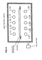
- Fig. 6 is a schematic view showing a heat treatment device that uses the filament lamp according to the exemplary embodiment of the invention.
- An object to be treated is disposed in the heat treatment device (chamber).
- filament lamps L1 a lamp L11, a lamp L12, a lamp L13, a lamp L14, and a lamp L15
- filament lamps L2 a lamp L21, a lamp L22, a lamp L23, a lamp L24, and a lamp L25
- a vacuum pump is connected to the heat treatment device, so that the inner space of the heat treatment device is maintained in a reduced-pressure atmosphere. Also, the object is held by support.
- the lamp is disposed in the reduced-pressure atmosphere as described above, the external lead cannot be coated with an insulator or the like. For this reason, it is useful to employ the glass pipe according to the exemplary embodiment of the invention. Furthermore, under the reduced-pressure atmosphere, the creeping discharge is generally likely to occur in the atmosphere of specific pressure by Paschen's Law. In the case of the filament lamp according to the exemplary embodiment of the invention, the creeping discharge is likely to occur in the atmospheric pressure of, for example, about 3 Pa to about 2000 Pa. For this reason, the glass pipe is useful.
- metal foils corresponding to the number of filaments does not mean that the number of filaments is necessarily equal to the number of metal foils.
- the filament F1 shown in Fig. 1 may be divided into a plurality of filaments in the longitudinal direction.
Landscapes
- Engineering & Computer Science (AREA)
- Manufacturing & Machinery (AREA)
- Resistance Heating (AREA)
- Non-Portable Lighting Devices Or Systems Thereof (AREA)
- Vessels And Coating Films For Discharge Lamps (AREA)
Abstract
Description
- This application claims priority from Japanese Patent Application No.
2008-19 3234, filed on July 28, 2008 - Devices and apparatuses consistent with the present invention relate to filament lamps, and, in particular, to filament lamps used for heating an object to be treated.
- In the process for manufacturing a solar cell, there are a thermal diffusion process for diffusing P-type semiconductors and a firing process for firing silver paste that is used as an electrode material. In the both processes, a semiconductor wafer or a glass substrate is heated to a high temperature, for example, 800 to 900°C by using a thermal diffusion furnace and a firing furnace.
- Meanwhile, this heat treatment device should uniformly heat the object to be treated to prevent difference in temperature according to location. For this reason, there has been proposed a filament lamp that is used as a light source, has a plurality of power supply paths in an arc tube, and can independently supply desired electric power to respective paths (see e.g.,
JP-A-2006-279008
Further, since such a filament lamp has a plurality of power supply paths in the arc tube, terminals whose number corresponds to the number of the power supply paths should be provided to sealing sections of the lamp. - However, since the heating temperature of the object is higher in the above-mentioned process for manufacturing a solar cell, the electric power to be supplied to the lamp has also been increased. Meanwhile, there is a high demand for miniaturization rather in its size as opposed to an increase. That is, there is a demand for a filament lamp that has a plurality of independent power supply structures and meets the high input without the increase in size.
- Exemplary embodiments of the present invention address the above disadvantages and other disadvantages not described above. However, the present invention is not required to overcome the disadvantages described above, and thus, an exemplary embodiment of the present invention may not overcome any of the disadvantages described above.
- Accordingly, it is an aspect of the present invention to provide a filament lamp that has a plurality of independent power supply paths and meets the high input without the increase in size.
- According to one or more aspects of the present invention, a filament lamp is provided. The filament lamp includes: a long light emitting section including a plurality of filaments aligned with one another in an axial direction of the light emitting section, wherein electric power is independently supplied to each of the filaments; a sealing section that seals the light emitting section, including: a first sealing section provided at one end of the light emitting section; and a second sealing section provided at the other end of the light emitting section; a plurality of metal foils embedded in the sealing section; a plurality of external leads each connected to a corresponding one of the metal foils and extending from the sealing section to the outside; and a plurality of glass pipes each provided on the sealing section so as to cover a corresponding one of the external leads.
- According to one or more aspects of the present invention, there is provided a heat treatment device including the filament lamp.
-
-
Fig. 1 is a view showing the entire configuration of a filament lamp according to an exemplary embodiment of the invention; -
Fig. 2 is a view showing the configuration of a sealing section of the filament lamp according to the exemplary embodiment of the invention; -
Fig. 3 is a view showing the configuration of the sealing section of the filament lamp according to the exemplary embodiment of the invention; -
Fig. 4 is a view showing a filament lamp according to another exemplary embodiment of the invention; -
Fig. 5 is a view showing a filament lamp according to still another exemplary embodiment of the invention; and -
Fig. 6 is a view showing a heat treatment device that uses the filament lamp according to the exemplary embodiment of the invention. - Exemplary embodiments of the present invention will be now described with reference to the drawings.
-
Fig. 1 is a view showing the entire configuration of a filament lamp according to an exemplary embodiment of the invention.
A lamp L includes a longlight emitting section 10, and sealing sections 20 (20a and 20b) that are formed at both ends of thelight emitting section 10. The lamp L has a tubular shape as a whole. An airtight space is formed in thelight emitting section 10, and thelight emitting section 10 is provided with a plurality of filaments F (F1, F2, and F3) that extends in the axial direction of thelight emitting section 10. The filaments F1, F2, and F3 are completely electrically isolated from one another. Specifically, the filament F1 is disposed in the middle of thelight emitting section 10, the filament F2 is disposed at one end of the light emitting section 10 (at the end close to thesealing section 20a), and the filament F3 is disposed at the other end of the light emitting section 10 (at the end close to thesealing section 20b). The filaments F1, F2, and F3 are aligned with one another so as to parallel to the central axis of thelight emitting section 10. - Metal foils 30 (31a, 32a, 33a, 31b, 32b, and 33b), which correspond to the number of the filaments F, are embedded in the sealing sections 20 (20a and 20b). Specifically, the
metal foil 31a corresponding to the filament F1, themetal foil 32a corresponding to the filament F2, and themetal foil 33a corresponding to the filament F2 are embedded in thesealing section 20a. Further, themetal foil 31 b corresponding to the filament F1, themetal foil 32b corresponding to the filament F3, and themetal foil 33b corresponding to the filament F3 are embedded in thesealing section 20b. - External leads 40 (41a, 42a, 43a, 41b, 42b, and 43b) extending outside the lamp and internal leads 50 (51a, 52a, 53a, 51b, 52b, and 53b) extending inside the
light emitting section 10 are connected to themetal foils 30. Specifically, theexternal lead 41a and theinternal lead 51a are connected to themetal foil 31a, theexternal lead 42a and theinternal lead 52a are connected to themetal foil 32a, and theexternal lead 43a and the internal lead 53a are connected to themetal foil 33a. Further, theexternal lead 41 b and theinternal lead 51 b are connected to themetal foil 31 b, theexternal lead 42b and theinternal lead 52b are connected to themetal foil 32b, and theexternal lead 43b and theinternal lead 53b are connected to themetal foil 33b. - Accordingly, one independent conduction path is formed of the
external lead 41 a, themetal foil 31 a, theinternal lead 51a, the filament F1, theinternal lead 51 b, themetal foil 31 b, and theexternal lead 41b. Predetermined electric power is supplied to theexternal lead 41 a and theexternal lead 41b, so that the filament F1 emits light. Likewise, one independent conduction path is formed of theexternal lead 42a, themetal foil 32a, theinternal lead 52a, the filament F2, the internal lead 53a, themetal foil 33a, and theexternal lead 43a. Predetermined electric power is supplied to theexternal lead 42a and theexternal lead 43b, so that the filament F2 emits light. In addition, one independent conduction path is formed of theexternal lead 42b, themetal foil 32b, theinternal lead 52b, the filament F3, theinternal lead 53b, themetal foil 33b, and theexternal lead 43b. Predetermined electric power is supplied to theexternal lead 42b and theexternal lead 43b, so that the filament F3 emits light.
As described above, in the filament lamp according to this embodiment, theexternal lead 42a and theexternal lead 43a, which correspond to the filament F2 and disposed at one end of thelight emitting section 10, are formed so as to protrude from thesealing section 20a that is close to the filament F2, and twoexternal leads light emitting section 10, are formed so as to protrude from thesealing section 20b that is close to the filament F3. - In the filament lamp, for example, electric power of 3 kW is supplied to the filament F1 disposed in the middle of the
light emitting section 10, and electric power of 600 W is supplied to the filaments F2 and F3 disposed at the ends of thelight emitting section 10. Meanwhile, the filaments F1, F2, and F3 may be turned on at the same time, but a part of filaments may be turned on and the other filaments may be turned off. - The filaments F are formed by closely winding, for example, a tungsten wire in the shape of a coil. An inert gas, such as argon (Ar) or nitrogen (N2), is enclosed in the
light emitting section 10 together with halogen, such as bromine (Br) or chlorine (Cl). Meanwhile, although not shown, anchors for supporting the filaments F or the internal leads 50 may be provided. The internal leads 50 may be coated with insulating members. The structure of the filament lamp according to the exemplary embodiment of the invention is referred to European Patent Application No.09003532.0, filed on Mar. 11, 2009 -
Fig. 2 is an enlarged view of thesealing section 20b, when seen in the same direction asFig. 1 . Glass pipes 60 (61b, 62b, and 63b) are fixed to the external leads 40 (41b, 42b and 43b), respectively. Since theglass pipes 60 are formed so as to cover theexternal leads 40 without coming in contact with the outer surfaces of theexternal leads 40, the creeping distance between adjacentexternal leads 40 is increased. Specifically, as shown in the figure, the creeping distance between theexternal lead 41b and theexternal lead 42b is substantially equal to the sum of the length twice as long as the length L1 of theexternal lead 41b (the length of a discontiguous portion) in theglass pipe 61b in the longitudinal direction, the length twice as long as the length L2 of theexternal lead 42b (the length of a discontiguous portion) in theglass pipe 62b, and the separation distance W1 between theexternal leads external lead 42b and theexternal lead 43b is substantially equal to the sum of the length twice as long as the length L2 of theexternal lead 42b (the length of the discontiguous portion) in theglass pipe 62b in a longitudinal direction, the length twice as long as the length L3 of theexternal lead 43b (the length of the discontiguous portion) in theglass pipe 63b, and the separation distance W2 between theexternal leads -
Fig. 3 is a partially enlarged view of thesealing section 20, when seen in the direction that is indicated by the arrow "A" shown inFig. 2 . Theglass pipe 60 is provided so as to correspond to theexternal lead 40 that protrudes from the end of thesealing section 20. Meanwhile, inFig. 3 , themetal foil 30, theexternal lead 40, and theglass pipe 60 are provided side by side in a vertical direction of a plane of paper. The inner surface of theglass pipe 60 is separated from theexternal lead 40 without coming in contact with the external lead. - In the case of the so-called "both-ends sealed filament lamp" including a long light emitting section (see e.g.,
JP-A-2001-210280 Fig. 5 ofJP-UM-A-1-161548 - In addition, in the filament lamp according to the exemplary embodiment, as described above, the end of the
glass pipe 60 facing the sealingsection 20 is integrally pinched and sealed together with the material that forms the sealingsection 20. Accordingly, quartz glass forming theglass pipe 60 and quartz glass forming the sealingsection 20 are melted and substantially integrated with each other. That is, if a recess is formed at the sealingsection 20 and a glass pipe is inserted into the recess, there is a possibility that creeping discharge occurs in the gap generated between the pipe and the recess. However, since the above-mentioned gap is not formed in the exemplary embodiment of the invention, it may be possible to completely prevent the creeping discharge generated in the gap. - Examples of numerical values for the filament lamp are as follows: the length of the sealing
section 20 in width is in a range of about 13 mm to about 18 mm, for example, 18 mm. The separation distance W between the adjacent external leads 40 is in a range of about 5 mm to about 7 mm, for example, 6 mm. Further, the length L of the external lead (the length of a discontiguous portion) covered by theglass pipe 60 in the longitudinal direction (in the axial direction) is in a range of about 5 mm to about 15 mm, for example, 10 mm. The outer diameter of theglass pipe 60 is φ13 mm, and the inner diameter of theglass pipe 60 is φ10.5 mm. Accordingly, the creeping distance is, for example, 26 mm. -
Fig. 4 is a view showing a filament lamp according to another exemplary embodiment of the invention. The filament lamp shown inFig. 1 includes three filaments to which electric power may be independently supplied, but the filament lamp shown inFig. 4 includes four filaments. This is the difference between the filament lamps. Filaments F11 and F12 are disposed in the middle of alight emitting section 10, a filament F2 is disposed at one end of the light emitting section 10 (at the end close to asealing section 20a), and a filament F3 is disposed at the other end of the light emitting section 10 (at the end close to asealing section 20b). The filaments F11, F12, F2, and F3 are aligned with one another so as to be parallel to the central axis of thelight emitting section 10. Even in the case of the filament lamp having the above-mentioned structure, glass pipes having the structure as shown inFigs. 2 and3 are formed at external leads that protrude from the sealingsections 20. Meanwhile, the filament lamp including four filaments is also referred toFig. 4 of European Patent Application No.09003532.0 -
Fig. 5 is a view showing a filament lamp according to another exemplary embodiment of the invention. In the filament lamp shown inFig. 1 or4 , the external leads, which correspond to the filament disposed in the vicinity of onesealing section 20, are protruded outwards from the sealingsection 20. However, in the exemplary embodiment, a plurality of external leads provided at onesealing section 20 correspond to different filaments, respectively. Specifically, three metal foils embedded in thesealing section 20a correspond to filaments F1, F2, and F3, respectively. Further, three metal foils embedded in thesealing section 20b correspond to the filaments F1, F2, and F3, respectively. Accordingly, as seen from the filaments, one terminal of each of all filaments protrudes from thesealing section 20a and the other terminal thereof protrudes from thesealing section 20b. Even in the case of the filament lamp of this structure, glass pipes of the structure shown inFigs. 2 and3 are provided to the external leads that protrude from the sealingsections 20. Meanwhile, only two filaments may be provided in the case of this structure. -
Fig. 6 is a schematic view showing a heat treatment device that uses the filament lamp according to the exemplary embodiment of the invention.
An object to be treated is disposed in the heat treatment device (chamber). Further, filament lamps L1 (a lamp L11, a lamp L12, a lamp L13, a lamp L14, and a lamp L15) are disposed so as to face the front surface of the object. Furthermore, filament lamps L2 (a lamp L21, a lamp L22, a lamp L23, a lamp L24, and a lamp L25) are disposed so as to face the back surface of the object. A vacuum pump is connected to the heat treatment device, so that the inner space of the heat treatment device is maintained in a reduced-pressure atmosphere. Also, the object is held by support.
If the lamp is disposed in the reduced-pressure atmosphere as described above, the external lead cannot be coated with an insulator or the like. For this reason, it is useful to employ the glass pipe according to the exemplary embodiment of the invention. Furthermore, under the reduced-pressure atmosphere, the creeping discharge is generally likely to occur in the atmosphere of specific pressure by Paschen's Law. In the case of the filament lamp according to the exemplary embodiment of the invention, the creeping discharge is likely to occur in the atmospheric pressure of, for example, about 3 Pa to about 2000 Pa. For this reason, the glass pipe is useful. - In the exemplary embodiment of the invention, "metal foils corresponding to the number of filaments" does not mean that the number of filaments is necessarily equal to the number of metal foils. For example, the filament F1 shown in
Fig. 1 may be divided into a plurality of filaments in the longitudinal direction. - While the present invention has been shown and described with reference to certain exemplary embodiments thereof, it will be understood by those skilled in the art that various changes in form and details may be made therein without departing from the spirit and scope of the invention as defined by the appended claims. It is aimed, therefore, to cover in the appended claim all such changes and modifications as fall within the true spirit and scope of the present invention.
Claims (7)
- A filament lamp comprising:a long light emitting section comprising a plurality of filaments aligned with one another in an axial direction of the light emitting section, wherein electric power is independently supplied to each of the filaments;a sealing section that seals the light emitting section, comprising:a first sealing section provided at one end of the light emitting section; anda second sealing section provided at the other end of the light emitting section;a plurality of metal foils embedded in the sealing section;a plurality of external leads each connected to a corresponding one of the metal foils and extending from the sealing section to the outside; anda plurality of glass pipes each provided on the sealing section so as to cover a corresponding one of the external leads.
- The filament lamp according to claim 1,
wherein the glass pipes are integrally sealed together with the sealing section. - The filament lamp according to claim 1,
wherein the number of the metal foils embedded in either the first sealing section or the second sealing section corresponds to the number of the filaments. - The filament lamp according to claim 1,
wherein the metal foils are aligned with each other in a direction orthogonal to the axial direction. - The filament lamp according to claim 1, wherein a separation distance between the adjacent external leads is in a range of about 5mm to about 7mm, and
the length of the external leads covered by the glass pipes in the axial direction is in a range of about 5mm to about 15 mm. - The filament lamp according to claim 2,
wherein the light emitting section comprises at least three filaments,
wherein a first one of the filaments is disposed near the first sealing section, and two external leads corresponding to the first one of the filaments extend from the first sealing section to the outside, and
wherein a second one of the filaments is disposed near the second sealing section, and two external leads corresponding to the second one of the filaments extend from the second sealing section to the outside. - A heat treatment device comprising: the filament lamp according to claim 1.
Applications Claiming Priority (1)
| Application Number | Priority Date | Filing Date | Title |
|---|---|---|---|
| JP2008193234A JP5315833B2 (en) | 2008-07-28 | 2008-07-28 | Filament lamp |
Publications (2)
| Publication Number | Publication Date |
|---|---|
| EP2154707A2 true EP2154707A2 (en) | 2010-02-17 |
| EP2154707A3 EP2154707A3 (en) | 2011-03-23 |
Family
ID=41344040
Family Applications (1)
| Application Number | Title | Priority Date | Filing Date |
|---|---|---|---|
| EP09166453A Withdrawn EP2154707A3 (en) | 2008-07-28 | 2009-07-27 | Filament lamp |
Country Status (6)
| Country | Link |
|---|---|
| US (1) | US8488953B2 (en) |
| EP (1) | EP2154707A3 (en) |
| JP (1) | JP5315833B2 (en) |
| KR (1) | KR101255409B1 (en) |
| CN (1) | CN101640164B (en) |
| TW (1) | TW201012287A (en) |
Cited By (1)
| Publication number | Priority date | Publication date | Assignee | Title |
|---|---|---|---|---|
| EP2105948A3 (en) * | 2008-03-27 | 2010-09-01 | Ushiodenki Kabushiki Kaisha | Filament lamp |
Families Citing this family (2)
| Publication number | Priority date | Publication date | Assignee | Title |
|---|---|---|---|---|
| US11963268B2 (en) * | 2019-06-19 | 2024-04-16 | Oregon State University | Resistance heater rod and method of making such |
| KR20210095059A (en) * | 2020-01-21 | 2021-07-30 | 에이에스엠 아이피 홀딩 비.브이. | Semiconductor processing chamber with filament lamps having nonuniform heat output |
Citations (4)
| Publication number | Priority date | Publication date | Assignee | Title |
|---|---|---|---|---|
| JPH01161548A (en) | 1987-12-18 | 1989-06-26 | Hitachi Ltd | Online file expansion method |
| JP2001210280A (en) | 2000-01-31 | 2001-08-03 | Toshiba Lighting & Technology Corp | Tube light bulb device and electric appliance device |
| JP2006279008A (en) | 2005-03-02 | 2006-10-12 | Ushio Inc | Heater and heating device provided with heater |
| JP2008193234A (en) | 2007-02-01 | 2008-08-21 | Konica Minolta Business Technologies Inc | Image processor, control method of image processor and control program of image processor |
Family Cites Families (38)
| Publication number | Priority date | Publication date | Assignee | Title |
|---|---|---|---|---|
| FR1317782A (en) * | 1961-03-16 | 1963-05-08 | ||
| FR1489101A (en) * | 1966-05-20 | 1967-07-21 | Lampes Elect Fab Reunies | Improvements to lamps used in optical systems |
| US3579021A (en) * | 1969-04-30 | 1971-05-18 | Sylvania Electric Prod | Incandescent lamp having linear output |
| US3634722A (en) * | 1970-03-30 | 1972-01-11 | Sylvania Electric Prod | Tungsten halogen lamp having improved filament support |
| NL7012669A (en) * | 1970-08-27 | 1972-02-29 | ||
| NL160679C (en) * | 1970-09-03 | 1979-11-15 | Philips Nv | ELECTRIC LIGHT BULB. |
| JPS57119451A (en) | 1981-01-17 | 1982-07-24 | Matsushita Electric Works Ltd | Fluorescent lamp |
| JPS57119451U (en) * | 1981-01-20 | 1982-07-24 | ||
| US4442374A (en) * | 1982-03-25 | 1984-04-10 | Gte Products Corporation | Dual length copier lamp |
| DE3236462A1 (en) * | 1982-10-01 | 1984-04-05 | Patent-Treuhand-Gesellschaft für elektrische Glühlampen mbH, 8000 München | HIGH PRESSURE DISCHARGE LAMP WITH BASE AND RELATED LAMP |
| US4710676A (en) * | 1985-08-15 | 1987-12-01 | Gte Products Corporation | Multi-level fuser lamp |
| CA1262170A (en) * | 1985-08-15 | 1989-10-03 | Steven L. Meade | Multi-level fuser lamp |
| JPS6267446A (en) | 1985-09-20 | 1987-03-27 | Toshiba Corp | Lattice board inspector |
| JPH0430758Y2 (en) * | 1985-10-17 | 1992-07-24 | ||
| JPH0992214A (en) * | 1995-09-26 | 1997-04-04 | Toshiba Lighting & Technol Corp | High-pressure metal vapor discharge lamp and its lighting device and lighting device |
| JPH1027574A (en) * | 1996-07-12 | 1998-01-27 | Koito Mfg Co Ltd | Discharge lamp arc tube and method for manufacturing arc tube |
| JP3225852B2 (en) * | 1996-09-26 | 2001-11-05 | ウシオ電機株式会社 | Lamp device |
| JP3668391B2 (en) * | 1999-07-12 | 2005-07-06 | 株式会社小糸製作所 | Arc tube for discharge lamp device and manufacturing method thereof |
| EP1193734A4 (en) * | 2000-03-08 | 2006-06-28 | Gs Yuasa Corp | Electric discharge lamp |
| US6495960B1 (en) * | 2000-03-08 | 2002-12-17 | Japan Storage Battery Co., Ltd. | Discharge lamp |
| WO2001071768A1 (en) * | 2000-03-21 | 2001-09-27 | Japan Storage Battery Co., Ltd. | Discharge lamp |
| DE10024709B4 (en) | 2000-05-18 | 2008-03-13 | Steag Rtp Systems Gmbh | Device for the thermal treatment of substrates |
| JP3636654B2 (en) * | 2000-11-14 | 2005-04-06 | 株式会社小糸製作所 | Arc tube |
| JP3543799B2 (en) * | 2001-10-17 | 2004-07-21 | ウシオ電機株式会社 | Short arc type ultra-high pressure discharge lamp |
| US6614008B2 (en) * | 2001-12-14 | 2003-09-02 | Xerox Corporation | Universal voltage fuser heater lamp |
| JP3875940B2 (en) * | 2002-06-12 | 2007-01-31 | オスラム・メルコ株式会社 | Discharge lamp cap |
| CN101111924B (en) * | 2005-02-17 | 2010-06-02 | 株式会社杰士汤浅 | Ceramic metal halide lamps with a rated lamp power of more than 450 W |
| JP2007095889A (en) * | 2005-09-28 | 2007-04-12 | Ushio Inc | Light irradiation heating method |
| JP4692249B2 (en) * | 2005-11-30 | 2011-06-01 | ウシオ電機株式会社 | Filament lamp |
| US20080005014A1 (en) * | 2006-07-03 | 2008-01-03 | Smith Steven W | System and method for providing property-secured credit card products |
| JP4893159B2 (en) * | 2006-08-24 | 2012-03-07 | ウシオ電機株式会社 | Filament lamp and light irradiation type heat treatment equipment |
| JP4868140B2 (en) * | 2006-08-31 | 2012-02-01 | ウシオ電機株式会社 | Filament lamp |
| CN101517699B (en) * | 2006-09-26 | 2010-09-29 | 哈利盛东芝照明公司 | Halogen lamps and methods of manufacturing halogen lamps |
| JP4893474B2 (en) * | 2007-05-29 | 2012-03-07 | ウシオ電機株式会社 | Filament lamp and light irradiation type heat treatment equipment |
| JP2009238552A (en) * | 2008-03-27 | 2009-10-15 | Ushio Inc | Filament lamp |
| JP4670886B2 (en) * | 2008-03-31 | 2011-04-13 | ウシオ電機株式会社 | Filament lamp |
| JP5125933B2 (en) * | 2008-09-22 | 2013-01-23 | ウシオ電機株式会社 | Filament lamp |
| JP5251398B2 (en) * | 2008-09-26 | 2013-07-31 | ウシオ電機株式会社 | Filament lamp |
-
2008
- 2008-07-28 JP JP2008193234A patent/JP5315833B2/en not_active Expired - Fee Related
-
2009
- 2009-06-02 TW TW098118210A patent/TW201012287A/en unknown
- 2009-06-26 KR KR1020090057751A patent/KR101255409B1/en not_active Expired - Fee Related
- 2009-07-16 CN CN2009101604277A patent/CN101640164B/en not_active Expired - Fee Related
- 2009-07-27 EP EP09166453A patent/EP2154707A3/en not_active Withdrawn
- 2009-07-27 US US12/509,559 patent/US8488953B2/en not_active Expired - Fee Related
Patent Citations (4)
| Publication number | Priority date | Publication date | Assignee | Title |
|---|---|---|---|---|
| JPH01161548A (en) | 1987-12-18 | 1989-06-26 | Hitachi Ltd | Online file expansion method |
| JP2001210280A (en) | 2000-01-31 | 2001-08-03 | Toshiba Lighting & Technology Corp | Tube light bulb device and electric appliance device |
| JP2006279008A (en) | 2005-03-02 | 2006-10-12 | Ushio Inc | Heater and heating device provided with heater |
| JP2008193234A (en) | 2007-02-01 | 2008-08-21 | Konica Minolta Business Technologies Inc | Image processor, control method of image processor and control program of image processor |
Cited By (1)
| Publication number | Priority date | Publication date | Assignee | Title |
|---|---|---|---|---|
| EP2105948A3 (en) * | 2008-03-27 | 2010-09-01 | Ushiodenki Kabushiki Kaisha | Filament lamp |
Also Published As
| Publication number | Publication date |
|---|---|
| TW201012287A (en) | 2010-03-16 |
| US8488953B2 (en) | 2013-07-16 |
| KR101255409B1 (en) | 2013-04-17 |
| CN101640164A (en) | 2010-02-03 |
| CN101640164B (en) | 2013-08-07 |
| US20100021147A1 (en) | 2010-01-28 |
| KR20100012809A (en) | 2010-02-08 |
| JP5315833B2 (en) | 2013-10-16 |
| EP2154707A3 (en) | 2011-03-23 |
| JP2010033798A (en) | 2010-02-12 |
Similar Documents
| Publication | Publication Date | Title |
|---|---|---|
| CN101685760B (en) | Filament lamp | |
| US9536729B2 (en) | Tubular light source having overwind | |
| US8488953B2 (en) | Filament lamp | |
| JP5251398B2 (en) | Filament lamp | |
| CN101546692B (en) | Filament lamp | |
| CN101488439A (en) | Lamp unit | |
| JP6120182B2 (en) | Both ends sealed short arc flash lamp | |
| JP4670886B2 (en) | Filament lamp | |
| JP5293453B2 (en) | Filament lamp | |
| JP5151773B2 (en) | Filament lamp | |
| EP1901330A2 (en) | Method for manufacturing hot cathode fluorescent lamp | |
| JP2010040262A (en) | Filament lamp | |
| TW202230450A (en) | Low-voltage ultraviolet lamp unit | |
| JP2010033858A (en) | Filament lamp | |
| JP2009129569A (en) | Discharge lamp and manufacturing method thereof | |
| JP2010033856A (en) | Filament lamp | |
| JP2000285869A (en) | Microwave discharge lamp device |
Legal Events
| Date | Code | Title | Description |
|---|---|---|---|
| PUAI | Public reference made under article 153(3) epc to a published international application that has entered the european phase |
Free format text: ORIGINAL CODE: 0009012 |
|
| AK | Designated contracting states |
Kind code of ref document: A2 Designated state(s): AT BE BG CH CY CZ DE DK EE ES FI FR GB GR HR HU IE IS IT LI LT LU LV MC MK MT NL NO PL PT RO SE SI SK SM TR |
|
| AX | Request for extension of the european patent |
Extension state: AL BA RS |
|
| PUAL | Search report despatched |
Free format text: ORIGINAL CODE: 0009013 |
|
| AK | Designated contracting states |
Kind code of ref document: A3 Designated state(s): AT BE BG CH CY CZ DE DK EE ES FI FR GB GR HR HU IE IS IT LI LT LU LV MC MK MT NL NO PL PT RO SE SI SK SM TR |
|
| AX | Request for extension of the european patent |
Extension state: AL BA RS |
|
| RIC1 | Information provided on ipc code assigned before grant |
Ipc: H01K 1/44 20060101ALI20110214BHEP Ipc: H01K 9/00 20060101AFI20100113BHEP |
|
| 17P | Request for examination filed |
Effective date: 20110922 |
|
| GRAP | Despatch of communication of intention to grant a patent |
Free format text: ORIGINAL CODE: EPIDOSNIGR1 |
|
| INTG | Intention to grant announced |
Effective date: 20170103 |
|
| STAA | Information on the status of an ep patent application or granted ep patent |
Free format text: STATUS: THE APPLICATION IS DEEMED TO BE WITHDRAWN |
|
| 18D | Application deemed to be withdrawn |
Effective date: 20170516 |