EP2154599A2 - Vorrichtung, Verfahren und Programm zur Informationsverarbeitung - Google Patents
Vorrichtung, Verfahren und Programm zur Informationsverarbeitung Download PDFInfo
- Publication number
- EP2154599A2 EP2154599A2 EP09166214A EP09166214A EP2154599A2 EP 2154599 A2 EP2154599 A2 EP 2154599A2 EP 09166214 A EP09166214 A EP 09166214A EP 09166214 A EP09166214 A EP 09166214A EP 2154599 A2 EP2154599 A2 EP 2154599A2
- Authority
- EP
- European Patent Office
- Prior art keywords
- function
- touch screen
- area
- basic function
- information processing
- Prior art date
- Legal status (The legal status is an assumption and is not a legal conclusion. Google has not performed a legal analysis and makes no representation as to the accuracy of the status listed.)
- Withdrawn
Links
Images





Classifications
-
- G—PHYSICS
- G06—COMPUTING OR CALCULATING; COUNTING
- G06F—ELECTRIC DIGITAL DATA PROCESSING
- G06F3/00—Input arrangements for transferring data to be processed into a form capable of being handled by the computer; Output arrangements for transferring data from processing unit to output unit, e.g. interface arrangements
- G06F3/01—Input arrangements or combined input and output arrangements for interaction between user and computer
- G06F3/048—Interaction techniques based on graphical user interfaces [GUI]
- G06F3/0487—Interaction techniques based on graphical user interfaces [GUI] using specific features provided by the input device, e.g. functions controlled by the rotation of a mouse with dual sensing arrangements, or of the nature of the input device, e.g. tap gestures based on pressure sensed by a digitiser
- G06F3/0488—Interaction techniques based on graphical user interfaces [GUI] using specific features provided by the input device, e.g. functions controlled by the rotation of a mouse with dual sensing arrangements, or of the nature of the input device, e.g. tap gestures based on pressure sensed by a digitiser using a touch-screen or digitiser, e.g. input of commands through traced gestures
-
- G—PHYSICS
- G06—COMPUTING OR CALCULATING; COUNTING
- G06F—ELECTRIC DIGITAL DATA PROCESSING
- G06F3/00—Input arrangements for transferring data to be processed into a form capable of being handled by the computer; Output arrangements for transferring data from processing unit to output unit, e.g. interface arrangements
- G06F3/01—Input arrangements or combined input and output arrangements for interaction between user and computer
- G06F3/048—Interaction techniques based on graphical user interfaces [GUI]
- G06F3/0481—Interaction techniques based on graphical user interfaces [GUI] based on specific properties of the displayed interaction object or a metaphor-based environment, e.g. interaction with desktop elements like windows or icons, or assisted by a cursor's changing behaviour or appearance
- G06F3/0482—Interaction with lists of selectable items, e.g. menus
Definitions
- the present invention relates to an information processing apparatus, method, and program, and particularly to an information processing apparatus, method, and program capable of easily setting imaging-related functions.
- a digital camera has a plurality of imaging-related functions.
- a user has conventionally carried out the following operation: That is, the user selects an icon representing a function that the user desires to perform.
- the digital camera then displays an image showing details of the function selected through the icon.
- the user sets the details of the function while viewing the image.
- the user carries out the operation described above by using a finger to press hardware buttons or software buttons (when a touch panel-equipped model is used).
- the user may not be able to set a desired function, or it may takes a long time for the user to set the function.
- An information processing apparatus includes touch screen means including a touch panel and a panel, and display control means for performing display control of displaying a symbol representing a first function in a first area of the touch screen means when the touch screen means detects that the first area is touched, whereas displaying a symbol representing a second function in a second area of the touch screen means when the touch screen means detects that the second area is touched with the first area remaining being touched.
- the display area of the touch screen means is divided into an upper right area, an upper left area, a lower right area, and a lower left area, and the lower right area is the first area and the lower left area is the second area.
- the display control means performs the display control of displaying the symbol representing the first or second function when the first or second area remains being touched at least for a predetermined period.
- the display control means further performs the display control of deleting the displayed symbol representing the first function when a first deleting condition is satisfied, whereas deleting the displayed symbol representing the second function when a second deleting condition is satisfied.
- the second deleting condition includes a condition that the symbol representing the first function is deleted.
- the first function is a set of a plurality of functions and the symbol representing the first function includes first function cards for the respective plurality of functions, each of the first function cards being an object mimicking a card representing a predetermined function
- the second function is a set of a plurality of functions and the symbol representing the second function includes second function cards for the respective plurality of functions, each of the second function cards being an object mimicking a card representing a predetermined function.
- the information processing apparatus further includes function setting means.
- function setting means When a card used to carry out a function setting operation is selected on the touch screen means from the plurality of first function cards and the plurality of second function cards and then a setting operation instructing the touch screen means to set a function identified by the card, the function setting means set the function, and the display control means further performs the display control, when the setting operation is performed, of displaying an image in which the selected card is turned over on the touch screen means.
- the setting operation is a finger's single tapping operation performed on the selected card or an operation of narrowing the distance between two fingers that touch the selected card.
- the information processing apparatus further includes touch panel means disposed on the opposite surface of the information processing apparatus to the surface on which the touch screen means is disposed, and the setting operation is a finger's single tapping operation performed on the touch panel means.
- An information processing method and program according to another embodiments of the invention are a method and program corresponding to the information processing apparatus according to the embodiment of the invention described above.
- the following control is made on a touch screen formed of a touch panel and a panel. That is, a symbol representing a first function is displayed in a first area of the touch screen when the touch screen detects that the first area is touched, whereas a symbol representing a second function is displayed in a second area of the touch screen when the touch screen detects that the second area is touched with the first area remaining being touched.
- the invention allows a function setting operation to be readily carried out.
- employing an imaging apparatus including a touch screen as an information processing apparatus allows an imaging-related function setting operation to be readily carried out.
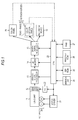
- Fig. 1 is a block diagram showing an exemplary configuration of an imaging apparatus as an embodiment of an information processing apparatus to which the invention is applied.
- the imaging apparatus includes a lens unit 11 through a touch panel 28.
- the lens unit 11 includes an imaging lens, a diaphragm, and a focus lens.
- An imaging device 12 such as a CCD (Charge Coupled Device), is disposed on the optical path along which subject light incident through the lens unit 11 travels.
- CCD Charge Coupled Device
- the imaging device 12 an analog signal processor 13, an A/D (Analog/Digital) converter 14, and a digital signal processor 15 are connected to each other in this order.
- the digital signal processor 15 is connected to a liquid crystal panel 17, a recording device 19, and a touch panel 28.
- the lens unit 11 is connected to an actuator 20 for adjusting the diaphragm, which is part of the lens unit 11, and moving the focus lens, which is part of the lens unit 11.
- the actuator 20 is also connected to a motor driver 21.
- the motor driver 21 drives and controls the actuator 20.
- a CPU 23 controls the entire imaging apparatus. To this end, the CPU 23 is connected to the analog signal processor 13, the A/D converter 14, the digital signal processor 15, the motor driver 21, a TG (Timing Generator) 22, an operation unit 24, an EEPROM (Electrically Erasable Programmable ROM) 25, a program ROM (Read Only Memory) 26, a RAM (Random Access Memory) 27, a touch panel 16, and the touch panel 28.
- the analog signal processor 13 the A/D converter 14
- the digital signal processor 15
- the motor driver 21 a TG (Timing Generator) 22
- an operation unit 24 an EEPROM (Electrically Erasable Programmable ROM) 25
- a program ROM Read Only Memory
- RAM Random Access Memory
- a touch screen 18 includes the touch panel 16 and the liquid crystal panel 17.
- the touch panel 28 is disposed on the opposite side of the imaging apparatus to the touch screen 18, that is, on the imaging lens side (see Figs. 2A and 2B , which will be described later).
- the recording device 19 is formed of, for example, a DVD (Digital Versatile Disc) or any other similar optical disc, a memory card or any other similar semiconductor memory, or any other suitable removable recording medium.
- the recording device 19 can be freely attached and detached to and from a body of the imaging apparatus.
- the EEPROM 25 stores a variety of types of information that has been set.
- the EEPROM 25 further stores other information, for example, information that should be held when the power is turned off.
- the program ROM 26 stores programs to be executed by the CPU 23 and data necessary for the CPU 23 to execute the programs.
- the RAM 27 serves as a work area used when the CPU 23 carries out a variety of processes, and temporarily stores necessary programs and data.
- the CPU 23 controls the components that form the imaging apparatus by executing the programs recorded in the program ROM 26.
- the CPU 23 carries out predetermined processes in response to signals from the touch panel 16 or the touch panel 28 and signals from the operation unit 24. Specific examples of the processes will be described later with reference to the flowcharts shown in Figs. 7 , 8 , and 11 .
- a user operates the operation unit 24, which in turn provides the CPU 23 with a signal corresponding to the operation.
- the touch screen 18 or the touch panel 28 when touched, for example, with a finger at an arbitrary position, in other words, when the user carries out a predetermined input operation, detects the coordinates of the touched position.
- An electric signal representing the detected coordinates (hereinafter referred to as a coordinate signal) is sent to the CPU 23.
- the CPU 23 derives the coordinates of the touched position from the coordinate signal, acquires predetermined information related to the coordinates, and carries out a predetermined process based on the information.
- the touch used herein includes not only static touch (touching only a single predetermined area) but also dynamic touch (touch that occurs when a finger or any other touching object follows a predetermined path). For example, opening a folding fan on an image or any other similar tracing operation performed by a finger is one form of the touch.
- the actuator 20 is driven to pull the lens unit 11 out of a housing of the imaging apparatus and push the lens unit 11 into the housing. Further, the actuator 20 is driven to adjust the diaphragm, which is part of the lens unit 11, and move the focus lens, which is part of the lens unit 11.
- the TG 22 provides the imaging device 12 with a timing signal under the control of the CPU 23.
- the timing signal controls the exposure period and other parameters in the imaging device 12.
- the imaging device 12 operates based on the timing signal provided from the TG 22 and receives subject light incident through the lens unit 11, and the subject light then undergoes photoelectric conversion.
- the imaging device 12 then provides the analog signal processor 13 with an analog image signal according to the amount of received light.
- the motor driver 21 drives the actuator 20 under the control of the CPU 23.
- the analog signal processor 13 carries out amplification and other analog signal processing on the analog image signal provided from the imaging device 12.
- the analog signal processor 13 provides the A/D converter 14 with the resultant analog image signal.
- the A/D converter 14 converts the analog image signal from the analog signal processor 13 into a digital image signal under the control of the CPU 23.
- the A/D converter 14 provides the digital signal processor 15 with the resultant digital image signal.
- the digital signal processor 15 carries out noise removal and other digital signal processing on the digital image signal provided from the A/D converter 14 under the control of the CPU 23.
- the digital signal processor 15 displays an image corresponding to the digital image signal on the liquid crystal panel 17.
- the digital signal processor 15 compresses and encodes the digital image signal provided from the A/D converter 14 in accordance with a predetermined compression and encoding scheme, for example, JPEG (Joint Photographic Experts Group).
- the digital signal processor 15 records the compressed and encoded digital image signal in the recording device 19.
- the digital signal processor 15 also reads the compressed and encoded digital image signal from the recording device 19 and decompresses and decodes the signal in accordance with a decompression and decoding scheme corresponding to the predetermined compression and encoding scheme.
- the digital signal processor 15 displays an image corresponding to the digital image signal on the liquid crystal panel 17.
- the digital signal processor 15 produces a frame image used to perform an AF (auto focus) function (hereinafter referred to as an AF frame) on the liquid crystal panel 17 under the control of the CPU 23.
- an AF frame auto focus function
- an image captured by the imaging device 12 is displayed on the liquid crystal panel 17.
- the AF frame is set on the image displayed on the liquid crystal panel 17.
- the focus control is carried out based on the image within the AF frame.
- the imaging apparatus has the AF function.
- the AF function includes not only the focus control function but also the function of setting the AF frame in an arbitrary position on the image displayed on the liquid crystal panel 17.
- the AF function further includes a function of controlling the position, the size, and other parameters of the AF frame only by operating the touch screen 18 formed of the liquid crystal panel 17 and the touch panel 16.
- the CPU 23 reads a program in the program ROM 26 and executes the program.
- the imaging apparatus further has an AE (Automatic Exposure) function and an AWB (Auto White Balance) function. These functions are also performed by instructing the CPU 23 to read programs in the program ROM 26 and execute them.
- the AF function, the AE function, and the AWB function are presented only by way of example of the functions provided in the imaging apparatus. That is, the imaging apparatus has a variety of imaging-related functions.
- imaging-related basic functions are referred to as basic functions
- imaging-related application functions are referred to as application functions.
- the basic functions are those frequently used
- the application functions are those less frequently used than the basic functions.
- the basic functions include not only the AF function, the AE function, and the AWB function described above but also "zoomed imaging,” “automatic imaging,” “flash setting,” “scene imaging,” “timer imaging,” and “macro imaging.”
- a reproducing function that allows an image capturing screen to transition to an image reproducing screen can also be one of the basic functions.
- the application functions include "video imaging,” “WB imaging,” “EV setting,” “ISO setting,” and “continuous imaging setting.”
- FIGs. 2A and 2B are perspective views showing an exemplary exterior configuration of the imaging apparatus in the example shown in Fig. 1 .
- the surface facing a subject to be imaged by the user that is, the surface through which the lens unit 11 is disposed
- a front surface the surface facing a subject to be imaged by the user
- the surface facing the user who images the subject that is, the surface on the side that is opposite the front surface
- a rear surface the surface facing the user who images the subject
- the surface disposed on the upper side and the surface disposed on the lower side when the user images the subject are referred to as an upper surface and a lower surface, respectively.
- Fig. 2A is a perspective view showing an exemplary exterior configuration of the front surface of the imaging apparatus
- Fig. 2B is a perspective view showing an exemplary exterior configuration of the rear surface of the imaging apparatus.
- the front surface of the imaging apparatus can be covered with a lens cover 47.
- Fig. 2A shows the state after the lens cover 47 on the front surface is slid downward and opened.
- an imaging lens 45 incorporated in the lens unit 11 and an AF illuminator 46 are disposed in this order in the right-to-left direction in an upper front portion from which the lens cover 47 is removed.
- the touch panel 28 is disposed in a lower front portion that is covered with the lens cover 47 and where the user holds the imaging apparatus when the user images a subject.
- the AF illuminator 46 also serves as a self-timer lamp.
- a zoom lever (TELE/WIDE) 41 On the upper surface of the imaging apparatus are disposed a zoom lever (TELE/WIDE) 41, a shutter button 42, a playback button 43, and a power button 44 in this order from the left-to-right direction in Fig. 2A .
- the zoom lever 41, the shutter button 42, the playback button 43, and the power button 44 are part of the operation unit 24 shown in Fig. 1 .
- the touch screen 18 is disposed over the rear surface of the imaging apparatus.
- the touch screen 18 is thus disposed on the rear surface of the imaging apparatus, the user, when imaging a subject, can uses the touch screen 18 to manipulate a GUI (Graphical User Interface) with the front surface of the imaging apparatus remaining facing the subject.
- GUI Graphic User Interface
- any of the basic functions described above can be set by using the touch screen 18 to manipulate the GUI.
- the user sets a desired one of the plurality of basic functions.
- symbols representing the basic functions are displayed on the touch screen 18.
- the forms of the symbols are not limited to specific ones.
- a card with the name of a basic function displayed thereon is prepared for each of the plurality of basic functions, and an object mimicking the card (hereinafter simply abbreviated to a basic function card) is displayed on the touch screen 18 (see Fig. 4 , which will be described later).
- the location where the basic function cards are displayed is not limited to a specific location. It is, however, preferable that the basic function cards are displayed at a location where the user can readily manipulate the cards, that is, a location where the user can readily touch the cards with a finger when a subject is being imaged.
- the plurality of basic function cards is collectively displayed in a lower right area of the touch screen (see Fig. 4 , which will be described later) . It is, of course, noted that the basic function cards may be displayed in a lower left area of the touch screen 18.
- a transition from the state in which none of the plurality of basic function cards is displayed on the touch screen 18 to the state in which the basic function cards are displayed is referred to as a basic function call.
- An exemplary operation of calling of the basic functions will be described with reference to Figs. 3 and 4 .
- the state of display on the touch screen 18 transitions from the state shown in Fig. 3 to the state shown in Fig. 4 . That is, a plurality of basic function cards CB overlapping with each other in the form of a fan is displayed in the lower right area of the touch screen 18, as shown in Fig. 4 .
- Each of the basic function cards CB is related to a single predetermined basic function.
- a single basic function card CB therefore has the name of the related basic function displayed thereon. As a result, the user only needs to view the name (text) displayed on the basic function card CB and can immediately identify the basic function related to the card.
- the basic function cards CB remain displayed unless a deleting condition for deleting the displayed basic functions is satisfied.
- a specific example of the deleting condition for deleting the displayed basic functions will be described later.
- the imaging apparatus 1 shown in Fig. 1 has not only the basic functions but also application functions as described above.
- the user sets a desired one of the plurality of application functions.
- symbols representing the application functions are displayed on the touch screen 18.
- the forms of the symbols are not limited to specific ones.
- a card with the name of an application function displayed thereon is prepared for each of the plurality of application functions, and an object mimicking the card (hereinafter simply abbreviated to an application function card) is displayed on the touch screen 18 (see Fig. 6 , which will be described later), as in the case of the basic functions.
- the location where the application function cards are displayed is not limited to a specific location. It is, however, preferable that the application function cards are displayed at a location where the user can readily manipulate the cards, that is, a location where the user can readily touch the cards with a finger when a subject is being imaged. It is further preferable that the basic function cards and the application function cards are displayed to be clearly distinguished from each other. Specifically, in the present embodiment, for example, the plurality of application function cards is collectively displayed on the side that is opposite the side on which plurality of basic function cards CB are displayed, that is, in a lower left area of the touch screen (see Fig. 6 , which will be described later). It is, of course, noted that the application function cards may be displayed in a lower right area of the touch screen 18 when the plurality of basic function cards CB is collectively displayed in a lower left area of the touch screen.
- the relationship between the basic functions and the application functions is not limited to a specific one. Examples of the relationship may include the following first and second relationships.
- first relationship the basic functions and the application functions are independent of each other from the viewpoint of functionality.
- second relationship more detailed functions of the basic functions are defined in the application functions. That is, in the second relationship, a basic function and an application function set a single complete function.
- the second relationship is employed in the present embodiment.
- the application functions are based on the basic functions, it is assumed that the basic function cards CB need to be displayed to display the application function cards. That is, the initial state of display on the touch screen 18 before the application function call is carried out is the state shown in Fig. 4 .
- the user touches a lower left area of the touch screen 18 of the imaging apparatus with a finger f2 that differs from the finger f1, as shown in Fig. 5 .
- the reason why the description "a finger f2 that differs from the finger f1" is made is that the deleting condition for deleting the displayed basic functions is satisfied if the finger f1 is released from the touch screen 18. That is, the basic function cards CB are deleted, and the prerequisite for displaying the application function cards is no longer present.
- the state of display on the touch screen 18 transitions from the state shown in Fig. 5 to the state shown in Fig. 6 . That is, a plurality of application function cards CA overlapping with each other in the form of a fan is displayed in the lower left area of the touch screen 18, as shown in Fig. 6 .
- Each of the application function cards CA is related to a single predetermined application function.
- a single application function card CA therefore has the name of the related application function displayed thereon. As a result, the user only needs to view the name (text) displayed on the application function card CA and can immediately identify the application function related to the card.
- the application function cards CA remain displayed unless the deleting condition for deleting the displayed basic functions or a deleting condition for deleting the displayed application functions is satisfied. Deleting the basic function cards CB can be excluded from the deleting conditions for deleting the displayed application functions. This can be understood as follows: the application function cards CA remain displayed unless the deleting condition for deleting the displayed application functions is satisfied. The deleting condition for deleting the displayed basic functions and the deleting condition for deleting the displayed application functions will be described later.
- a basic function can be called through an operation using only the finger f1, that is, only one hand.
- an operation using the fingers f1 and f2 is necessary to call an application function. That is, when the user calls an application function while holding the imaging apparatus with both hands, an operation using the finger f1 of the right hand and the finger f2 of the left hand, that is, both hands, is necessary.
- the basic functions, which are frequently set can be clearly distinguished from the application functions, which are less frequently set, by thus clearly differentiating the basic function calling operation from the application function calling operation.
- the user can readily set a desired function with the basic functions, which are frequently set, and the application functions, which are less frequently set, concurrently presented.
- a basic function calling process a process of calling a basic function
- an application function calling process a process of calling an application function
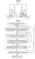
- Fig. 7 is a flowchart describing an example of the basic function calling process.
- the state in which captured image data is ready to be recorded in the recording device 19 that is, the state in which pressing the shutter button 42 immediately initiates the recording operation
- an image capturing state the state in which captured image data is ready to be recorded in the recording device 19, that is, the state in which pressing the shutter button 42 immediately initiates the recording operation.
- the CPU 23 judges whether or not a lower right area of the touch screen 18 remains being touched at least for a predetermined period.
- the CPU 23 keeps receiving a coordinate signal for the predetermined period from the touch panel 16, which forms the touch screen 18.
- the judgment in the step S1 is YES, that is, it is judged that the lower right area of the touch screen 18 remains being touched at least for the predetermined period, and the control proceeds to the process in the step S2.
- the CPU 23 controls the digital signal processor 15 to display the basic function cards CB in the lower right area of the touch screen 18. That is, the state of display on the touch screen 18 transitions from the state shown in Fig. 3 to the state shown in Fig. 4 .
- the CPU 23 judges whether or not the deleting condition for deleting the displayed basic functions is satisfied.
- the deleting condition for deleting the displayed basic functions is not limited to a specific one.
- the deleting condition employed in the present embodiment is satisfied when at least one of the following first to third conditions is satisfied.
- a first condition is defined as follows: The user presses the shutter button 42 with the basic function cards CB displayed.
- a second condition is defined as follows: The user touches a monitoring screen area of the touch screen 18 except the area where the basic function cards CB or (and) the application function cards CA are displayed.
- a third condition is defined as follows: The touch screen 18 does not detect that the finger f1 has touched a lower left area of the touch screen 18 for a predetermined period.
- the judgment in the step S3 is NO and the control returns to the process in the step S2.
- the process in the step S2 and the following processes are then repeated. That is, the basic function cards CB remain displayed in the lower right area of the touch screen 18 until at least one of the first to third conditions is satisfied. That is, the state of display on the touch screen 18 remains to be the state shown in Fig. 4 .
- step S3 the judgment in the step S3 is YES and the control proceeds to the process in the step S4.
- the CPU 23 controls the digital signal processor 15 to delete the displayed basic function cards in the lower right area of the touch screen 18.
- the CPU 23 judges whether or not the image capturing state is completed.
- the judgment in the step S5 is NO as long as the state of the imaging apparatus remains to be the image capturing state.
- the control therefore returns to the process in the step S1, and the process in the step S1 and the following processes are repeated. That is, the loop process including the step S1 through the step S5 is repeated as long as the state of the imaging apparatus remains to be the image capturing state.
- the basic function calling process has been described above, the basic function call and the application function call can be concurrently carried out under a certain condition. That is, in the present embodiment, since more detailed functions of the basic functions are defined in the application functions, the application function cards CA can be displayed only when the basic function cards CB are displayed.
- Fig. 8 is a flowchart describing an example of the application function calling process.
- step S21 the CPU 23 judges whether or not the basic function cards CB are displayed.
- step S21 When no basic function card CB is displayed, the judgment in the step S21 is NO and the control returns to the process in the step S21. The process in the step S21 and the following processes are then repeated. That is, the process in the step S21 is repeated until the basic function cards CB are displayed in the lower right area of the touch screen 18.
- step S2 in the basic function calling process shown in Fig. 7 is carried out so that the basic function cards CB are displayed in the lower right area of the touch screen 18, that is, when the state of display on the touch screen 18 transitions to the state shown in Fig. 4 , the judgment in the step S21 is YES and the control proceeds to the process in the step S22.
- the CPU 23 judges whether or not a lower left area of the touch screen 18 remains being touched at least for a predetermined period.
- the CPU 23 keeps receiving a coordinate signal for the predetermined period from the touch panel 16, which forms the touch screen 18.
- the CPU 23 keeps receiving the coordinate signal (a signal representing the coordinates of the lower left area) for the predetermined period from the touch panel 16, which forms the touch screen 18, with the basic function cards CB displayed, the judgment in the step S22 is YES, that is, it is judged that the lower left area of the touch screen 18 remains being touched at least for the predetermined period, and the control proceeds to the process in the step S23.
- the coordinate signal a signal representing the coordinates of the lower left area
- the CPU 23 controls the digital signal processor 15 to display the application function cards CA in the lower left area of the touch screen 18. That is, the state of display on the touch screen 18 transitions from the state shown in Fig. 5 to the state shown in Fig. 6 .
- the CPU 23 judges whether or not the deleting condition for deleting the displayed application functions is satisfied.
- the deleting condition for deleting the displayed application functions is not limited to a specific one.
- the deleting condition employed in the present embodiment is satisfied when at least one of the following first to third conditions is satisfied.
- a first condition is defined as follows: The user presses the shutter button 42 with the application function cards CA displayed (and with the basic function cards CB also displayed in this case).
- a second condition is defined as follows: The user touches a monitoring screen area of the touch screen 18 except the area where the basic function cards CB and the application function cards CA are displayed.
- a third condition is defined as follows: The touch screen 18 does not detect that at least one of the fingers f1 and f2 has touched a lower right area or a lower left area of the touch screen 18 (a lower right area and a lower left area when both the basic function cards CB and the application function cards CA are displayed) for a predetermined period.
- the reason why the description "at least one of the fingers f1 and f2" is made is that the third condition is also satisfied in the following case:
- the touch screen 18 does not detect that the finger f1 has touched it; as a result, the judgment in the step S3 in Fig. 7 is YES; and the basic function cards CB are deleted in the process in the step S4.
- the judgment in the step S24 is NO and the control returns to the process in the step S23.
- the process in the step S23 and the following processes are then repeated. That is, the application function cards CA remain displayed in the lower left area of the touch screen 18 until at least one of the first to third conditions is satisfied. Further, when none of the first to third conditions described above is satisfied, none of the deleting conditions for deleting the displayed basic functions is also satisfied in the step S3 in Fig. 7 .
- the basic function cards CB therefore remain displayed in the lower right area of the touch screen 18. That is, the state of display on the touch screen 18 remains to be the state shown in Fig. 6 .
- step S24 the judgment in the step S24 is YES and the control proceeds to the process in the step S25.
- the CPU 23 controls the digital signal processor 15 to delete the displayed application function cards CA in the lower left area of the touch screen 18.
- the judgment in the step S24 is YES in response to the user's action of pressing the shutter button 42 or the user' s action of touching a monitoring screen area of the touch screen 18 except the area where the basic function cards CB and the application function cards CA are displayed, and hence the application function cards CA are deleted in the process in the step S25, the judgment in the step S3 in Fig. 7 is YES and the basic function cards CB are also deleted in the process in the step S4.
- the judgment in the step S24 is YES in response to the fact that the touch screen 18 does not detect that the finger f2 has touched a lower left area of the touch screen 18 for a predetermined period with the touch screen 18 detecting that the finger f1 remains touching the lower right area of the touch screen 18, and hence the application function cards CA are deleted in the process in the step S25
- the judgment in the step S3 in Fig. 7 is NO and the control returns to the process in the step S2.
- the basic function cards CB remain displayed.
- the CPU 23 judges whether or not the image capturing state is completed.
- the judgment in the step S26 is NO as long as the state of the imaging apparatus remains to be the image capturing state.
- the control therefore returns to the process in the step S21, and the process in the step S21 and the following processes are repeated. That is, the loop process including the step S21 through the step S26 is repeated as long as the state of the imaging apparatus remains to be the image capturing state.
- FIG. 9 describes an example of the operations of calling a basic function and an application function of the imaging apparatus but different from the example shown in Figs. 3 to 6 .
- Fig. 9 the user traces a left-side portion of the touch screen 18 of the imaging apparatus with the finger f1 in the down-to-up direction.
- the application function cards CA/basic function cards CB are then sequentially displayed along a lower-to-upper area of the left-side portion of the touch screen 18 touched with the finger f1.
- the user traces the left-side portion of the touch screen 18 of the imaging apparatus with the finger f1 in the up-to-down direction with the application function cards CA/basic function cards CB displayed.
- the application function cards CA/basic function cards CB are then sequentially deleted along the upper-to-lower area of the left-side portion of the touch screen 18 touched with the finger f1.
- the direction of the tracing operation is, of course, not limited to a specific direction, but the directions described above may be reversed. That is, the application function cards CA/basic function cards CB are displayed in the up-to-down direction, whereas they are deleted in the down-to-up direction.
- Figs. 10A to 10C describe an exemplary operation of setting a basic function.
- Setting a basic function in the present embodiment includes turning the function off and turning the function on. Turning the function off means that the basic function is disabled. On the other hand, turning the function on means that the basic function is enabled so that it is performed through an operation.
- Fig. 10A shows the state in which a plurality of basic function cards CB is displayed. That is, Fig. 10A shows the same state as that shown in Fig. 4 . Specifically, as a result of the user's action of keeping touching a lower right area of the touch screen 18 with the finger f1 at least for a predetermined period, the plurality of basic function cards CB is displayed.
- Fig. 10B the user selects a basic function card CB1 on which a basic function the user wants to set is displayed. That is, the user touches the basic function card CB1 with the finger f1 and pulls it out upward, as shown in Fig. 10B .
- the basic function card CB1 is thus selected. That is, pulling out the basic function card CB1 corresponds to selecting the basic function card CB1.
- Judging whether or not the basic function card CB1 is being pulled out can be made by using the CPU 23 to monitor a coordinate signal from the touch panel 16, which forms the touch screen 18. That is, the CPU 23 can derive the path of the finger f1 from the time-series coordinate signals. The CPU 23 then detects whether or not the basic function card CB1 is being pulled out based on the derivation result. The CPU 23 controls the digital signal processor 15 to produce an image showing the basic function card CB1 moving along the path of the finger f1 and display the image on the touch screen 18. Alternatively, animation may be used to express the basic function card CB1 being pulled out.
- the processes carried out by the CPU 23 described above are carried out in the same manner in other GUI operations, which will be described later.
- the operation of turning over the basic function card CB1 can be, for example, an operation of tapping the basic function card CB1 once with the finger f1 (single tapping).
- the fact that the basic function card CB1 shows its front side means that the basic function displayed on the card is turned on.
- the fact that the basic function card CB1 shows its back side means that the basic function displayed on the card is turned off. Since the basic function card CB1 is turned over so that the back side appears in the example shown in Figs. 10A to 10C , the basic function displayed on the card is changed from the turned-on state to the turned-off state.
- the basic function card CB1 on which words "macro function" are displayed is selected so that the basic function card CB1 is turned over.
- the macro function is therefore is set to the turned-off state.
- the basic function card CB1 having been turned over so that the function is turned off is displayed in a different form so that the basic function card CB1 is differentiated from other basic function cards CB with their functions turned on.
- the form itself in which a card is displayed is not limited to a specific one as long as the form in which a card with its function turned on differs from the form in which the card with its function turned off.
- the basic function cards CB with their functions turned on including the basic function card CB1 shown in Figs. 10A and 10B
- the basic function card CB1 with its function turned off is displayed in gray.
- the turned-off function of the basic function card CB1 can be turned back on by carrying out the series of operations described with reference to Figs. 10A to 10C , that is, the operation of reselecting the basic function card CB1 and the operation of turning over again the basic function card CB1 so that the front side appears.
- setting a basic function includes turning the function on and turning the function off. Some of the basic functions, however, may not be fully expressed by the expressions of turning the functions on and off. For such a basic function, settable items may be displayed on the back side of the corresponding basic function card CB. In this case, the user may turn over the basic function card CB and then select a desired item to set the function.
- Fig. 11 is a flowchart describing, among the processes carried out in the imaging apparatus shown in Fig. 1 , an exemplary process to be carried out in response to the operation of setting a basic function shown in Figs. 10A to 10C (hereinafter referred to as a set function changing process). It is noted that an application function can be set in the same manner as a basic function by replacing the words "basic function” with the words "application function” in each step described below.
- the set function changing process is also initiated when the state of the imaging apparatus action transitions to the image capturing state.
- step S41 the CPU 23 judges whether or not the basic function cards CB are displayed.
- step S41 When no basic function card CB is displayed, the judgment in the step S41 is NO and the control returns to the process in the step S41. The process in the step S41 and the following processes are then repeated. That is, the process in the step S41 is repeated until the basic function cards CB are displayed in the lower right area of the touch screen 18.
- step S2 in the basic function calling process shown in Fig. 7 is carried out so that the basic function cards CB are displayed in the lower right area of the touch screen 18, that is, when the state of display on the touch screen 18 transitions to the state shown in Fig. 4 , the judgment in the step S41 is YES and the control proceeds to the process in the step S42.
- the CPU 23 judges whether or not the basic function card CB1 has been selected (the finger f1 has pulled out the basic function card CB1).
- the judgment in the step S42 is NO and the control returns to the process in the step S41.
- the process in the step S41 and the following processes are then repeated. That is, the loop process including the steps S41 and S42 is repeated until the finger f1 pulls out the basic function card CB1 with the basic function card CB1 displayed.
- step S42 the judgment in the step S42 is YES and the control proceeds to the process in the step S43.
- the CPU 23 judges whether or not the basic function has been set (the finger f1 has turned over the basic function card CB1).
- the judgment in the step S43 is NO and the control proceeds to the process in the step S47.
- the process in the step S47 and the following processes will be described later.
- step S43 the judgment in the step S43 is YES and the control proceeds to the process in the step S44.
- the CPU 23 changes the state of the selected basic function from the initial state to the inverse state.
- the CPU 23 changes the state of the basic function to the turned-off state, because the initial state of the basic function displayed on the card (selected basic function) is the turned-on state of the basic function.
- the CPU 23 changes the state of the basic function to the turned-on state, because the initial state of the basic function displayed on the card (selected basic function) is the turned-off state of the basic function.
- the CPU 23 controls the digital signal processor 15 to put the basic function card CB1 back to the position where it was originally displayed. That is, the digital signal processor 15 puts the basic function card CB1 having been pulled out in the process in the step S42 back into the lower right area of the touch screen 18, which is the position where the basic function card CB1 was originally displayed.
- the CPU 23 judges whether or not the image capturing state is completed.
- the judgment in the step S46 is NO as long as the state of the imaging apparatus remains to be the image capturing state.
- the control therefore returns to the process in the step S41, and the process in the step S41 and the following processes are repeated. That is, the loop process including the step S41 through the step S46 is repeated as long as the state of the imaging apparatus remains to be the image capturing state.
- the CPU 23 judges whether or not the touch screen detects a user's action of putting the basic function card CB1 back to its original position.
- step S47 When the basic function card CB1 has been put back to its original position, the judgment in the step S47 is YES and the control proceeds to the process in the step S45. That is, in the process in the step S45, the basic function card CB1 having been pulled out in the process in the step S42 is put back into the lower right area of the touch screen 18, which is the position where the basic function card CB1 was originally displayed. The control then proceeds to the process in the step S46. Since the process in the step S46 and the following processes have been already described, no description thereof will be made.
- the CPU 23 judges whether or not a predetermined period has elapsed since the basic function card CB1 was pulled out in the process in the step S42.
- the CPU 23 judges whether or not no operation is carried out on the basic function card CB1 having been pulled out in the step S42 but a predetermined period has elapsed.
- the judgment in the step S48 is NO and the control returns to the process in the step S43.
- the process in the step S43 and the following processes are then repeated.
- the judgment in the step S48 is YES and the control proceeds to the process in the step S45. That is, when no operation has been carried out on the basic function card CB1 having been pulled out in the step S42 but the predetermined period has elapsed, the basic function card CB1 is put back into the lower right area of the touch screen 18, which is the position where the basic function card CB1 was originally displayed, in the process in the step S45. The control then proceeds to the process in the step S46. Since the process in the step S46 and the following processes have been already described, no description thereof will be made.
- FIG. 10A and 10C An example of the operation of setting a basic function has been described with reference to Figs. 10A and 10C , and then the set function changing process corresponding to the operation in the example shown in Figs. 10A to 10C has been described with reference to Fig. 11 .
- the operation of setting a basic function is, however, not particularly limited to the operation in the example shown in Figs. 10A to 10C .
- Another example of the operation of setting a basic function will be described with reference to Figs. 12A to 13B .
- Figs. 12A to 12C describe an example of the operation of setting a basic function but different from the example shown in Figs. 10A to 10C .
- Fig. 12A the user selects a basic function card CB1 on which a basic function the user wants to set is displayed. That is, the user touches the basic function card CB1 with fingers f1 and f2 and pulls it out upward, as shown in Fig. 12A .
- the basic function card CB1 is thus selected. That is, pulling out the basic function card CB1 with the fingers f1 and f2 corresponds to selecting the basic function card CB1.
- selecting the basic function card CB1 may be carried out by pulling it out by only the finger f1, as shown in Fig. 10B .
- the user then sets the basic function. That is, the user uses the fingers f1 and f2 to turn over the basic function card CB1 so that the front and back sides are reversed.
- the user moves the finger f1 to the upper end of the basic function card CB1 and narrows the distance between the fingers f1 and f2, as shown in Figs. 12B and 12C .
- the selected basic function card CB1 is then turned over (the selected basic function card CB1 is displayed as if it were turned over).
- the basic function card CB1 on which words "macro function" are displayed is selected so that the basic function card CB1 is turned over.
- the macro function is therefore set to the turned-off state.
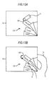
- Figs. 13A and 13B describe an example of the operation of setting a basic function but different from the examples shown in Figs. 10A to 10C and Figs. 12A to 12C .
- the touch panel 28 disposed on the front side (on the side where the lens unit 11 is disposed) of the imaging apparatus is used. As described above, the touch panel 28 is disposed on the side that is opposite the touch screen 18 (see Figs. 2A and 2B ).
- Fig. 13A the user selects a basic function card CB1 on which a basic function the user wants to set is displayed. That is, the user touches the basic function card CB1 with the finger f1 and pulls it out upward, as shown in Fig. 13A .
- the basic function card CB1 is thus selected. That is, pulling out the basic function card CB1 corresponds to selecting the basic function card CB1.
- the user then sets the basic function. That is, the user uses the fingers f1 and f2 to turn over the basic function card CB1 so that the front and back sides are reversed.
- the user taps once the touch panel 28 formed on the imaging lens side of the imaging apparatus (single tapping) with the finger f2 while touching the basic function card CB1 having been pulled out with the finger f1, as shown in Fig. 13B .
- the selected basic function card CB1 is then turned over (the selected basic function card CB1 is displayed as if it were turned over).
- the basic function card CB1 on which words "macro function" are displayed is selected so that the basic function card CB1 is turned over.
- the macro function is therefore set to the turned-off state.
- the operation of setting a basic function is not limited to that in the example shown in Figs. 13A and 13B .
- the user touches the basic function card CB1 with the finger f1 to turn over the basic function card CB1 so that the front and back sides are reversed.
- the finger f1 does not need to touch the basic function card CB1.
- the operation of turning over the basic function card CB1 so that the front and back sides are reversed may be carried out as follows: The user pulls out the basic function card CB1 with the finger f1, releases the finger f1 from the basic function card CB1, and taps once the touch panel 28 with the finger f2 (single tapping).
- the imaging apparatus to which the invention is applied displays objects mimicking cards in the real life (the basic function cards CB and the application function cards CA in the example described above) in order to display a variety of imaging-related functions.
- the variety of imaging-related functions can be presented to the user in an easy-to-use method.
- the user can intuitively understand the variety of imaging-related functions.
- a CPU 101 carries out a variety of processes in accordance with programs recorded in a ROM (Read Only Memory) 102 or programs loaded from a storage unit 108 to a RAM (Random Access Memory) 103. Further, the RAM 103 as appropriate stores data necessary for the CPU 101 to carry out the variety of processes.
- ROM Read Only Memory
- RAM Random Access Memory
- the CPU 101, the ROM 102, and the RAM 103 are connected to one another via a bus 104.
- An input/output interface 105 is also connected to the bus 104.
- the input/output interface 105 is connected to an input unit 106 formed of a keyboard, a mouse, and other components, an output unit 107, the storage unit 108 formed of a hard disc drive and other components, and a communication unit 109 formed of a modem, a terminal adapter, and other components.
- the communication unit 109 controls communication with other apparatus (not shown) via a network including the Internet.
- the input/output interface 105 is also connected to a drive 110 as necessary, into which a removable medium 111, such as a magnetic disk, an optical disk, a magneto-optical disc, and a semiconductor memory, is loaded as appropriate.
- a removable medium 111 such as a magnetic disk, an optical disk, a magneto-optical disc, and a semiconductor memory.
- Computer programs read from any of the above media are installed in the storage unit 108 as necessary.
- programs that form the software are installed via the network or by any of the recording media, for example, to a computer incorporated in dedicated hardware or a general-purpose personal computer that can perform a variety of functions by installing a variety of programs.
- recording media containing such programs are formed of not only the removable medium (packaged medium) 111 ( Fig. 14 ) distributed to users to provide the programs separately from the apparatus body, such as a magnetic disk (including a floppy disk), an optical disk (including a CD-ROM (Compact Disk-Read Only Memory) and a DVD (Digital Versatile Disk)), a magneto-optical disk (including an MD (Mini-Disk)), and a semiconductor memory, on which the programs are recorded, but also the program ROM 26 shown in Fig. 1 , the ROM 102, a hard disk contained in the storage unit 108 shown in Fig. 14 , and other components, which are incorporated in advance in the apparatus body and provided to the users and on which the programs are recorded.
- a magnetic disk including a floppy disk
- an optical disk including a CD-ROM (Compact Disk-Read Only Memory) and a DVD (Digital Versatile Disk)
- MD Magneto-optical disk
- semiconductor memory on which the programs
- the steps describing the programs recorded in any of the recording media include not only processes that are sequentially carried out in a time-series manner but also processes that are not necessarily carried out in a time-series manner but are carried out concurrently or individually.
- a display device in which the display operation is controlled by the information processing apparatus to which the invention is applied is a liquid crystal display device, specifically, the liquid crystal display panel 17.
- the invention is also applicable to not only a liquid crystal display panel but also a display device configured as follows: the display operation is instructed on a frame or field basis (frames or fields form video images and each of the frames or fields is hereinafter referred to as a segment); a plurality of pixels that form a single segment are formed of display elements; and at least part of the display elements can remain in a display state.
- hold-type display elements a display device having a screen formed of hold-type display elements
- a hold-type display device a display device having a screen formed of hold-type display elements
- a liquid crystal display device has been presented only by way of example of a hold-type display device, and the invention is applicable to any hold-type display device.
- the invention is applicable to not only a hold-type display device but also, for example, a flat-panel, self-luminous display device using organic EL (Electro Luminescent) devices as light-emitting elements. That is, the invention is applicable to any display device including display elements that display a plurality of pixels that form an image.
- the display device described above is referred to as a pixel-type display device.
- a single pixel is not, in particular, necessarily related to a single display element.
Landscapes
- Engineering & Computer Science (AREA)
- General Engineering & Computer Science (AREA)
- Theoretical Computer Science (AREA)
- Human Computer Interaction (AREA)
- Physics & Mathematics (AREA)
- General Physics & Mathematics (AREA)
- User Interface Of Digital Computer (AREA)
- Studio Devices (AREA)
- Position Input By Displaying (AREA)
Applications Claiming Priority (1)
| Application Number | Priority Date | Filing Date | Title |
|---|---|---|---|
| JP2008206623 | 2008-08-11 |
Publications (1)
| Publication Number | Publication Date |
|---|---|
| EP2154599A2 true EP2154599A2 (de) | 2010-02-17 |
Family
ID=40940496
Family Applications (1)
| Application Number | Title | Priority Date | Filing Date |
|---|---|---|---|
| EP09166214A Withdrawn EP2154599A2 (de) | 2008-08-11 | 2009-07-23 | Vorrichtung, Verfahren und Programm zur Informationsverarbeitung |
Country Status (4)
| Country | Link |
|---|---|
| US (1) | US20100037135A1 (de) |
| EP (1) | EP2154599A2 (de) |
| JP (1) | JP4840474B2 (de) |
| CN (1) | CN101651779B (de) |
Families Citing this family (27)
| Publication number | Priority date | Publication date | Assignee | Title |
|---|---|---|---|---|
| JP5219929B2 (ja) | 2008-07-31 | 2013-06-26 | ソニー株式会社 | 情報処理装置および方法、並びにプログラム |
| JP5326802B2 (ja) * | 2009-05-19 | 2013-10-30 | ソニー株式会社 | 情報処理装置、画像拡大縮小方法及びそのプログラム |
| JP5463739B2 (ja) | 2009-06-03 | 2014-04-09 | ソニー株式会社 | 撮像装置、画像処理方法及びプログラム |
| JP5466993B2 (ja) * | 2010-05-10 | 2014-04-09 | 株式会社 ミックウェア | 情報処理装置、情報処理方法、およびプログラム |
| USD642590S1 (en) * | 2010-06-08 | 2011-08-02 | Microsoft Corporation | Display screen with an icon |
| JP2012174247A (ja) * | 2011-02-24 | 2012-09-10 | Kyocera Corp | 携帯電子機器、接触操作制御方法および接触操作制御プログラム |
| JP5855862B2 (ja) | 2011-07-07 | 2016-02-09 | オリンパス株式会社 | 撮像装置、撮像方法およびプログラム |
| US20130019175A1 (en) * | 2011-07-14 | 2013-01-17 | Microsoft Corporation | Submenus for context based menu system |
| USD728597S1 (en) * | 2012-08-29 | 2015-05-05 | Samsung Electronics Co., Ltd. | Digital camera with a graphical user interface |
| USD727938S1 (en) * | 2012-08-29 | 2015-04-28 | Samsung Electronics Co., Ltd. | Digital camera with a graphical user interface |
| USD729828S1 (en) * | 2012-08-29 | 2015-05-19 | Samsung Electronics Co., Ltd | Digital camera with a graphical user interface |
| USD728598S1 (en) * | 2012-08-29 | 2015-05-05 | Samsung Electronics Co., Ltd. | Digital camera with a graphical user interface |
| USD728596S1 (en) * | 2012-08-29 | 2015-05-05 | Samsung Electronics Co., Ltd. | Digital camera with a graphical user interface |
| USD728599S1 (en) * | 2012-09-18 | 2015-05-05 | Samsung Electronics Co., Ltd. | Digital camera with a graphical user interface |
| USD727939S1 (en) * | 2012-09-18 | 2015-04-28 | Samsung Electronics Co., Ltd. | Digital camera with a graphical user interface |
| USD728600S1 (en) * | 2012-09-18 | 2015-05-05 | Samsung Electronics Co., Ltd. | Digital camera with a graphical user interface |
| USD727940S1 (en) * | 2012-09-18 | 2015-04-28 | Samsung Electronics Co., Ltd. | Digital camera with a graphical user interface |
| CN103838476B (zh) * | 2012-11-26 | 2018-05-22 | 腾讯科技(深圳)有限公司 | 数据的处理方法及触摸屏终端 |
| KR102092330B1 (ko) * | 2013-06-20 | 2020-03-23 | 삼성전자주식회사 | 촬영 제어 방법 및 그 전자 장치 |
| JP6153007B2 (ja) * | 2013-07-19 | 2017-06-28 | 株式会社コナミデジタルエンタテインメント | 操作システム、操作制御方法、操作制御プログラム |
| US10037130B2 (en) | 2013-09-13 | 2018-07-31 | Samsung Electronics Co., Ltd. | Display apparatus and method for improving visibility of the same |
| CN104169860B (zh) * | 2013-11-08 | 2019-04-05 | 华为技术有限公司 | 智能终端及用于显示其输入操作界面的方法 |
| WO2015149375A1 (en) * | 2014-04-04 | 2015-10-08 | Shell Internet (Beijing) Security Technology Co., Ltd. | Device, method, and graphical user interface for managing multiple display windows |
| WO2016006149A1 (ja) * | 2014-07-08 | 2016-01-14 | ソニー株式会社 | 撮像制御装置、撮像制御方法及びプログラム |
| USD754727S1 (en) * | 2014-09-18 | 2016-04-26 | 3M Innovative Properties Company | Display screen or portion thereof with animated graphical user interface |
| JP6109282B2 (ja) * | 2015-12-09 | 2017-04-05 | オリンパス株式会社 | 電子機器、撮像方法およびプログラム |
| DK180081B1 (en) | 2018-06-01 | 2020-04-01 | Apple Inc. | Access to system user interfaces on an electronic device |
Citations (1)
| Publication number | Priority date | Publication date | Assignee | Title |
|---|---|---|---|---|
| JP2008206623A (ja) | 2007-02-26 | 2008-09-11 | Newgin Corp | 遊技機 |
Family Cites Families (31)
| Publication number | Priority date | Publication date | Assignee | Title |
|---|---|---|---|---|
| US346313A (en) * | 1886-07-27 | Chair | ||
| US354700A (en) * | 1886-12-21 | Stop-and-waste connection for tanks | ||
| US5463725A (en) * | 1992-12-31 | 1995-10-31 | International Business Machines Corp. | Data processing system graphical user interface which emulates printed material |
| JPH08286829A (ja) * | 1995-04-18 | 1996-11-01 | Hitachi Ltd | メニュー制御システム |
| US5956035A (en) * | 1997-05-15 | 1999-09-21 | Sony Corporation | Menu selection with menu stem and submenu size enlargement |
| US7800592B2 (en) * | 2005-03-04 | 2010-09-21 | Apple Inc. | Hand held electronic device with multiple touch sensing devices |
| FR2776415A1 (fr) * | 1998-03-20 | 1999-09-24 | Philips Consumer Communication | Appareil electronique comportant un ecran et procede pour afficher des graphismes |
| US7359003B1 (en) * | 2001-11-09 | 2008-04-15 | Synerdyne Corporation | Display, input and form factor for portable instruments |
| US7111788B2 (en) * | 2002-04-22 | 2006-09-26 | Nokia Corporation | System and method for navigating applications using a graphical user interface |
| US7656393B2 (en) * | 2005-03-04 | 2010-02-02 | Apple Inc. | Electronic device having display and surrounding touch sensitive bezel for user interface and control |
| US7180524B1 (en) * | 2002-09-30 | 2007-02-20 | Dale Axelrod | Artists' color display system |
| JP2004185258A (ja) * | 2002-12-03 | 2004-07-02 | Hitachi Ltd | 情報処理装置 |
| US7663605B2 (en) * | 2003-01-08 | 2010-02-16 | Autodesk, Inc. | Biomechanical user interface elements for pen-based computers |
| JP2005317041A (ja) * | 2003-02-14 | 2005-11-10 | Sony Corp | 情報処理装置、情報処理方法、及びプログラム |
| US20040221243A1 (en) * | 2003-04-30 | 2004-11-04 | Twerdahl Timothy D | Radial menu interface for handheld computing device |
| US7490295B2 (en) * | 2004-06-25 | 2009-02-10 | Apple Inc. | Layer for accessing user interface elements |
| JP2006067157A (ja) * | 2004-08-26 | 2006-03-09 | Sony Corp | 情報処理装置および方法、並びにプログラム |
| KR101058011B1 (ko) * | 2004-10-01 | 2011-08-19 | 삼성전자주식회사 | 터치 스크린을 이용한 디지털 카메라 조작 방법 |
| JP2006139615A (ja) * | 2004-11-12 | 2006-06-01 | Access Co Ltd | 表示装置、メニュー表示プログラムおよびタブ表示プログラム |
| CN100592247C (zh) * | 2005-09-21 | 2010-02-24 | 鸿富锦精密工业(深圳)有限公司 | 多层次菜单显示装置及其显示控制方法 |
| US20070166004A1 (en) * | 2006-01-10 | 2007-07-19 | Io.Tek Co., Ltd | Robot system using menu selection card having printed menu codes and pictorial symbols |
| KR100672605B1 (ko) * | 2006-03-30 | 2007-01-24 | 엘지전자 주식회사 | 아이템 선택 방법 및 이를 위한 단말기 |
| CN100381997C (zh) * | 2006-04-29 | 2008-04-16 | 怡利电子工业股份有限公司 | 触控式按键的菜单选择方法 |
| US20090006996A1 (en) * | 2006-08-07 | 2009-01-01 | Shoumen Saha | Updating Content Within A Container Document For User Groups |
| US8736557B2 (en) * | 2006-09-11 | 2014-05-27 | Apple Inc. | Electronic device with image based browsers |
| JP4481289B2 (ja) * | 2006-11-14 | 2010-06-16 | 株式会社コナミデジタルエンタテインメント | 項目選択装置、項目選択方法、ならびに、プログラム |
| US8814676B2 (en) * | 2007-02-09 | 2014-08-26 | Igt | Universal player control for casino game graphic assets |
| EP2017707B1 (de) * | 2007-07-06 | 2017-04-12 | Dassault Systèmes | Vorrichtung für eine graphische Benutzerschnittstelle und Verfahren zur Navigation zwischen zusammenhängenden Objekten |
| US20090037813A1 (en) * | 2007-07-31 | 2009-02-05 | Palo Alto Research Center Incorporated | Space-constrained marking menus for mobile devices |
| US20090327955A1 (en) * | 2008-06-28 | 2009-12-31 | Mouilleseaux Jean-Pierre M | Selecting Menu Items |
| US8274484B2 (en) * | 2008-07-18 | 2012-09-25 | Microsoft Corporation | Tracking input in a screen-reflective interface environment |
-
2009
- 2009-06-04 JP JP2009134663A patent/JP4840474B2/ja not_active Expired - Fee Related
- 2009-07-23 EP EP09166214A patent/EP2154599A2/de not_active Withdrawn
- 2009-07-29 US US12/511,717 patent/US20100037135A1/en not_active Abandoned
- 2009-08-11 CN CN2009101633157A patent/CN101651779B/zh not_active Expired - Fee Related
Patent Citations (1)
| Publication number | Priority date | Publication date | Assignee | Title |
|---|---|---|---|---|
| JP2008206623A (ja) | 2007-02-26 | 2008-09-11 | Newgin Corp | 遊技機 |
Also Published As
| Publication number | Publication date |
|---|---|
| JP2010067260A (ja) | 2010-03-25 |
| JP4840474B2 (ja) | 2011-12-21 |
| US20100037135A1 (en) | 2010-02-11 |
| CN101651779A (zh) | 2010-02-17 |
| CN101651779B (zh) | 2011-12-07 |
Similar Documents
| Publication | Publication Date | Title |
|---|---|---|
| EP2154599A2 (de) | Vorrichtung, Verfahren und Programm zur Informationsverarbeitung | |
| KR101947822B1 (ko) | 화상 표시 제어 장치 및 화상 표시 제어 방법 | |
| EP2149839A2 (de) | Vorrichtung, Verfahren und Programm zur Informationsverarbeitung | |
| JP5652652B2 (ja) | 表示制御装置および方法 | |
| US9891814B2 (en) | Display control apparatus and method for displaying information related to icons | |
| CN102754063B (zh) | 用于执行多任务的设备和方法 | |
| EP2151747A2 (de) | Vorrichtung, Verfahren und Programm zur Informationsverarbeitung | |
| US20130222666A1 (en) | User interface for a digital camera | |
| US20100053342A1 (en) | Image edit method and apparatus for mobile terminal | |
| US20130208163A1 (en) | Camera shutter key display apparatus and method | |
| EP2530577A2 (de) | Anzeigevorrichtung und Verfahren | |
| US20150253951A1 (en) | Imaging apparatus and control method thereof | |
| US9973686B2 (en) | Image capturing control apparatus, image capturing control method to control display based on user input | |
| US9621809B2 (en) | Display control apparatus and method for controlling the same | |
| EP2631756B1 (de) | Benutzerschnittstelle für eine Digitalkamera | |
| JP5335474B2 (ja) | 画像処理装置および画像処理方法 | |
| WO2024255348A1 (zh) | 信息传输方法及电子设备 | |
| JP2013115692A (ja) | 撮像装置及び撮像装置に用いる制御プログラム | |
| JP2013115691A (ja) | 撮像装置及び撮像装置に用いる制御プログラム | |
| US20130162689A1 (en) | Display control apparatus and method | |
| HK1189073B (en) | User interface for a digital camera |
Legal Events
| Date | Code | Title | Description |
|---|---|---|---|
| PUAI | Public reference made under article 153(3) epc to a published international application that has entered the european phase |
Free format text: ORIGINAL CODE: 0009012 |
|
| 17P | Request for examination filed |
Effective date: 20090723 |
|
| AK | Designated contracting states |
Kind code of ref document: A2 Designated state(s): AT BE BG CH CY CZ DE DK EE ES FI FR GB GR HR HU IE IS IT LI LT LU LV MC MK MT NL NO PL PT RO SE SI SK SM TR |
|
| AX | Request for extension of the european patent |
Extension state: AL BA RS |
|
| RTI1 | Title (correction) |
Free format text: INFORMATION PROCESSING APPARATUS WITH TOUCH SCREEN, METHOD, AND PROGRAM |
|
| STAA | Information on the status of an ep patent application or granted ep patent |
Free format text: STATUS: THE APPLICATION HAS BEEN WITHDRAWN |
|
| 18W | Application withdrawn |
Effective date: 20130419 |