EP2154392A1 - Paroi de séparation pour un palier en caoutchouc commutable, à amortissement hydraulique - Google Patents
Paroi de séparation pour un palier en caoutchouc commutable, à amortissement hydraulique Download PDFInfo
- Publication number
- EP2154392A1 EP2154392A1 EP09008663A EP09008663A EP2154392A1 EP 2154392 A1 EP2154392 A1 EP 2154392A1 EP 09008663 A EP09008663 A EP 09008663A EP 09008663 A EP09008663 A EP 09008663A EP 2154392 A1 EP2154392 A1 EP 2154392A1
- Authority
- EP
- European Patent Office
- Prior art keywords
- clamping element
- partition
- ring
- nozzle
- nozzle disc
- Prior art date
- Legal status (The legal status is an assumption and is not a legal conclusion. Google has not performed a legal analysis and makes no representation as to the accuracy of the status listed.)
- Granted
Links
Images


Classifications
-
- F—MECHANICAL ENGINEERING; LIGHTING; HEATING; WEAPONS; BLASTING
- F16—ENGINEERING ELEMENTS AND UNITS; GENERAL MEASURES FOR PRODUCING AND MAINTAINING EFFECTIVE FUNCTIONING OF MACHINES OR INSTALLATIONS; THERMAL INSULATION IN GENERAL
- F16F—SPRINGS; SHOCK-ABSORBERS; MEANS FOR DAMPING VIBRATION
- F16F13/00—Units comprising springs of the non-fluid type as well as vibration-dampers, shock-absorbers, or fluid springs
- F16F13/04—Units comprising springs of the non-fluid type as well as vibration-dampers, shock-absorbers, or fluid springs comprising both a plastics spring and a damper, e.g. a friction damper
- F16F13/06—Units comprising springs of the non-fluid type as well as vibration-dampers, shock-absorbers, or fluid springs comprising both a plastics spring and a damper, e.g. a friction damper the damper being a fluid damper, e.g. the plastics spring not forming a part of the wall of the fluid chamber of the damper
- F16F13/08—Units comprising springs of the non-fluid type as well as vibration-dampers, shock-absorbers, or fluid springs comprising both a plastics spring and a damper, e.g. a friction damper the damper being a fluid damper, e.g. the plastics spring not forming a part of the wall of the fluid chamber of the damper the plastics spring forming at least a part of the wall of the fluid chamber of the damper
- F16F13/10—Units comprising springs of the non-fluid type as well as vibration-dampers, shock-absorbers, or fluid springs comprising both a plastics spring and a damper, e.g. a friction damper the damper being a fluid damper, e.g. the plastics spring not forming a part of the wall of the fluid chamber of the damper the plastics spring forming at least a part of the wall of the fluid chamber of the damper the wall being at least in part formed by a flexible membrane or the like
- F16F13/105—Units comprising springs of the non-fluid type as well as vibration-dampers, shock-absorbers, or fluid springs comprising both a plastics spring and a damper, e.g. a friction damper the damper being a fluid damper, e.g. the plastics spring not forming a part of the wall of the fluid chamber of the damper the plastics spring forming at least a part of the wall of the fluid chamber of the damper the wall being at least in part formed by a flexible membrane or the like characterised by features of partitions between two working chambers
-
- F—MECHANICAL ENGINEERING; LIGHTING; HEATING; WEAPONS; BLASTING
- F16—ENGINEERING ELEMENTS AND UNITS; GENERAL MEASURES FOR PRODUCING AND MAINTAINING EFFECTIVE FUNCTIONING OF MACHINES OR INSTALLATIONS; THERMAL INSULATION IN GENERAL
- F16F—SPRINGS; SHOCK-ABSORBERS; MEANS FOR DAMPING VIBRATION
- F16F13/00—Units comprising springs of the non-fluid type as well as vibration-dampers, shock-absorbers, or fluid springs
- F16F13/04—Units comprising springs of the non-fluid type as well as vibration-dampers, shock-absorbers, or fluid springs comprising both a plastics spring and a damper, e.g. a friction damper
- F16F13/26—Units comprising springs of the non-fluid type as well as vibration-dampers, shock-absorbers, or fluid springs comprising both a plastics spring and a damper, e.g. a friction damper characterised by adjusting or regulating devices responsive to exterior conditions
- F16F13/262—Units comprising springs of the non-fluid type as well as vibration-dampers, shock-absorbers, or fluid springs comprising both a plastics spring and a damper, e.g. a friction damper characterised by adjusting or regulating devices responsive to exterior conditions changing geometry of passages between working and equilibration chambers, e.g. cross-sectional area or length
Definitions
- the invention relates to a partition for a switchable hydraulically damping rubber bearing with an elastomeric spring body and two spaces for the hydraulic fluid, a working space and a compensation chamber, the two spaces are separated by the partition, which has a nozzle disc and a disc-like, with Passages provided clamping element covered and resting on the nozzle disc membrane, wherein the spaces communicate hydraulically with each other via a closable by an actuator passage opening and a damping channel.
- Partitions of this type are used in hydraulically damping rubber bearings.
- rubber bearings of this type a support bearing and a support for receiving the load is present, which are interconnected by an elastomeric spring body.
- Inside the warehouse there are two spaces for the hydraulic fluid, namely a working room and a compensation room.
- the two rooms are separated by a partition.
- the partition is provided with a damping channel, which hydraulically connects the two spaces.
- This damping channel is used for damping of low-frequency, large-amplitude oscillations.
- a closable via an actuator passage opening is present in the middle of the partition, which is used to eradicate idling vibrations open.
- a membrane is inserted in the partition wall, which serves to attenuate high-frequency, small-amplitude oscillations.
- a hydraulically damping bearing of the type in question is in the DE 198 07 868 C2 shown. Such a bearing is for versatile purposes, especially in motor vehicles, can be used.
- the invention has for its object to provide a partition for a switchable, hydraulically switchable rubber bearing, which is as simple as possible in their construction and which enables a simple way of clamping the membrane to the nozzle disk.
- the present on the plug-in boom arms represent spring elements, which with decoupled switch bearing with its radially inner stops the Press the clamping element against the membrane and thereby clamp the membrane to the nozzle plate.
- the clamping element is held by the nozzle disk.
- the nozzle disc has at its outer edge radially inwardly facing hooks whose lugs engage with play on the outer edge of the clamping element.
- the clamping element itself has indentations as passages for the hooks of the nozzle disk on its outer edge.
- On the outer ring of the nozzle disk of the plug ring is placed.
- the plug ring itself is provided with a plurality of inwardly directed spring-shaped arms, which abut with their projecting lugs on the inner ring of the clamping element. To form the damping channel, the nozzle disk and the plug ring cooperate.
- the outer edge of the nozzle disk and the inside of the plug ring is provided with annular groove-shaped recesses which form the damping channel.
- the plug ring has on its underside a part of the inner wall of the channel forming annular shoulder.
- the plug ring itself is made of plastic.
- the plug ring On its outer side, the plug ring has a circumferential flange, which is covered by a collar of the nozzle disk.
- the clamping element is provided with a pipe inserted into the central passage opening of the partition with play. This nozzle protrudes slightly beyond the lower surface of the passage opening of the nozzle plate, so that the actuator comes to rest on the nozzle during the closing operation of the passage opening.
- the clamping element itself is made of a light metal.
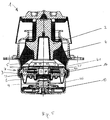
- the rubber bearing 1 shown in the figures is a hydraulically damping, reversible bearing. In its essential structure it consists of the support body 2 and the support 3. Support body 2 and support 3 are connected by the existing of an elastomeric spring body 4 of conical shape. In the located in the bearing 1 rooms 5 and 6, a pressure fluid is included, which is pulled up to dampen vibrations. It is in the room 5 to the working space and the room 6 to the compensation room. The two rooms 5 and 6 are separated from each other by the partition 7. On the top of the working space 5 is enclosed by the support body 2 together with the spring body 4. The compensation chamber 6 is bordered on its underside by the rolling diaphragm 8.
- the rolling diaphragm 8 is held centrally by the piston 9, which in turn is connected to the elastomeric spring 10.
- the space between the rolling diaphragm 8 and the elastomer spring 10 is vented through openings 11.
- the piston 9 is pressed against the spring pressure of the spring 10 downward and opens the passage opening 13 in the partition 7.
- venting through the vacuum port 12 is through
- the spring pressure of the spring 10 of the piston 9 is pushed upward and closes in its upper position, the passage opening 13 in the partition 7.
- the partition 7 consists of the nozzle plate 14, the clamping element 15 and the diaphragm 16.
- the nozzle plate 14 and the clamping element 15 are provided with passages 17 and 18, which are superimposed.
- the clamping element 15 is with its outer edge 19 (see Fig. 4 ) with play positively held by the nozzle disk.
- the inner edge 20 is pressed by the arms 21 in the direction of the nozzle disk 14.
- the booms 21 are attached to the plug ring 22, which is plugged onto the outer ring 23 of the nozzle disk 14.
- the male ring 22 with three arms 21 is visible.
- the clamping element 15 is held on the outer edge 19 by the hook 24 attached to the nozzle plate 14.
- the clamping element 15 at its outer edge 19, the indentations 25 as passages for the hooks 24.
- On the outer edge 26 of the nozzle plate 14 of the plug ring 22 is placed.
- the inwardly directed, resilient cantilever 21 are present.
- These booms 21 are equipped with the protruding lugs 27 which rest against the inner edge 20 of the clamping element 15.
- the outer edge 26 of the nozzle disk 14 and the plug ring 22 are provided with the annular groove-shaped recesses 28, 29 which form the damping channel 30, which connects the two working spaces 5 and 6 with each other. Therefor the damping channel 30 is provided with the inlets and outlets 31, 32.
- the plug ring 22 is provided on its underside with the peripheral flange 35, which is surrounded by a collar 36 of the nozzle disk 14.
- the clamping element 15 has a nozzle 37 which is inserted with clearance in the passage opening 13. This nozzle 37 protrudes slightly beyond the lower level of the passage opening 13 of the nozzle disk. In this way, the piston 9 can lift the clamping element 15 against the spring pressure from the arms 21 and thereby release the membrane 16.
- the plug ring is made of a plastic and the clamping element itself made of a light metal.
- the FIG. 5 shows an embodiment of the switchable rubber bearing 1, which can be used for higher loads.
- the basic structure of the bearing 1 corresponds to that in the FIG. 1 described.
- the support body 2 is connected via the spring body 4 to the support 3.
- the working space 5 is separated from the compensation chamber 6 by the partition wall 7.
- In the partition is a central passage opening 13 which can be closed by the piston 9 in connection with the central part 40 of the rolling diaphragm 8.
- the piston 9 pushes the clamping element 15 via the nozzle 37 upwards.
- the bearing 1 is here equipped with a spring clip 41 spring plate.
- This clamping spring 41 is formed by a ring 42, the inwardly directed tongue-like boom 21 has.
- the boom 21 With their tongue ends 43 are the boom 21 in recesses the inner edge 20 of the clamping member 15.
- the inner edge 20 is provided with upwardly over the top 44 of the clamping member 15 projecting support tabs 45 with the recesses.
- the ring 42 of the clamping spring 41 is placed on top of the plug ring 22 and caulked in an annular groove.
- the outer edge of the plug ring 22 is additionally provided with a latching lug, which additionally holds the ring 42 in its position.
- the bearing 1 is provided with a spring 46, which is inserted into the interior of the piston 9 and in addition to the elastomeric spring 10, the piston 9 presses in its closed position. The spring 46 pushes the piston 9 and thus also the clamping element 15 upwards and thus releases the membrane 16.
Landscapes
- Engineering & Computer Science (AREA)
- General Engineering & Computer Science (AREA)
- Mechanical Engineering (AREA)
- Combined Devices Of Dampers And Springs (AREA)
- Vibration Prevention Devices (AREA)
Applications Claiming Priority (1)
| Application Number | Priority Date | Filing Date | Title |
|---|---|---|---|
| DE102008037897.6A DE102008037897B4 (de) | 2008-08-15 | 2008-08-15 | Trennwand für ein umschaltbares, hydraulisch dämpfendes Gummilager |
Publications (2)
| Publication Number | Publication Date |
|---|---|
| EP2154392A1 true EP2154392A1 (fr) | 2010-02-17 |
| EP2154392B1 EP2154392B1 (fr) | 2011-03-16 |
Family
ID=41278509
Family Applications (1)
| Application Number | Title | Priority Date | Filing Date |
|---|---|---|---|
| EP09008663A Not-in-force EP2154392B1 (fr) | 2008-08-15 | 2009-07-02 | Paroi de séparation pour un palier en caoutchouc commutable, à amortissement hydraulique |
Country Status (3)
| Country | Link |
|---|---|
| EP (1) | EP2154392B1 (fr) |
| AT (1) | ATE502228T1 (fr) |
| DE (2) | DE102008037897B4 (fr) |
Families Citing this family (1)
| Publication number | Priority date | Publication date | Assignee | Title |
|---|---|---|---|---|
| DE102010021193B4 (de) * | 2010-05-21 | 2012-10-25 | Carl Freudenberg Kg | Trennwand für ein Hydrolager |
Citations (3)
| Publication number | Priority date | Publication date | Assignee | Title |
|---|---|---|---|---|
| DE19807868A1 (de) * | 1998-02-25 | 1999-09-09 | Freudenberg Carl Fa | Hydraulisch dämpfendes Lager |
| EP1099875A1 (fr) * | 1999-11-09 | 2001-05-16 | Hutchinson | Procédé pour atténuer des vibrations, support antivibratoire hydraulique actif, et véhicule comprenant un tel support |
| US20070138718A1 (en) * | 2005-12-15 | 2007-06-21 | Tokai Rubber Industries, Ltd. | Fluid filled vibration damping device and method of manufacturing the same |
Family Cites Families (1)
| Publication number | Priority date | Publication date | Assignee | Title |
|---|---|---|---|---|
| DE10348964A1 (de) * | 2003-10-22 | 2005-06-09 | Carl Freudenberg Kg | Hydrolager |
-
2008
- 2008-08-15 DE DE102008037897.6A patent/DE102008037897B4/de not_active Expired - Fee Related
-
2009
- 2009-07-02 AT AT09008663T patent/ATE502228T1/de active
- 2009-07-02 EP EP09008663A patent/EP2154392B1/fr not_active Not-in-force
- 2009-07-02 DE DE502009000451T patent/DE502009000451D1/de active Active
Patent Citations (4)
| Publication number | Priority date | Publication date | Assignee | Title |
|---|---|---|---|---|
| DE19807868A1 (de) * | 1998-02-25 | 1999-09-09 | Freudenberg Carl Fa | Hydraulisch dämpfendes Lager |
| DE19807868C2 (de) | 1998-02-25 | 2001-06-28 | Freudenberg Carl Fa | Hydraulisch dämpfendes Lager |
| EP1099875A1 (fr) * | 1999-11-09 | 2001-05-16 | Hutchinson | Procédé pour atténuer des vibrations, support antivibratoire hydraulique actif, et véhicule comprenant un tel support |
| US20070138718A1 (en) * | 2005-12-15 | 2007-06-21 | Tokai Rubber Industries, Ltd. | Fluid filled vibration damping device and method of manufacturing the same |
Also Published As
| Publication number | Publication date |
|---|---|
| ATE502228T1 (de) | 2011-04-15 |
| EP2154392B1 (fr) | 2011-03-16 |
| DE102008037897A1 (de) | 2010-02-25 |
| DE102008037897B4 (de) | 2014-03-20 |
| DE502009000451D1 (de) | 2011-04-28 |
Similar Documents
| Publication | Publication Date | Title |
|---|---|---|
| DE102012005991B4 (de) | Flüssigkeitsgefüllte Antivibrationsvorrichtung | |
| DE102012004659B4 (de) | Flüssigkeitsgefüllte Antivibrationsvorrichtung | |
| DE68919306T2 (de) | Hydraulisch gedämpfte Lagervorrichtung. | |
| DE60015065T2 (de) | Schaltbares, flüssigkeitsgefülltes und schwingungsisolierendes Lager | |
| EP1022483B1 (fr) | Support de montage commutable à amortissement hydraulique et à deux chambres | |
| DE10005180C1 (de) | Dämpfventil, insbesondere für einen Schwingungsdämpfer | |
| DE19603639C2 (de) | Fluidgefüllte elastische Lagerung mit einer Resonanzeinrichtung | |
| WO2016192722A1 (fr) | Élément d'amortissement pour une conduite hydraulique | |
| DE3342300C2 (fr) | ||
| DE102017007999A1 (de) | Schaltbares Hydrolager | |
| EP2855943B1 (fr) | Maître cylindre | |
| DE102019208413A1 (de) | Bremssystemdämpfvorrichtung | |
| EP2154392B1 (fr) | Paroi de séparation pour un palier en caoutchouc commutable, à amortissement hydraulique | |
| DE19807868C2 (de) | Hydraulisch dämpfendes Lager | |
| DE19712895C2 (de) | Schwingungsdämpfer mit richtungsabhängigem Voröffnungsquerschnitt | |
| EP1918592B2 (fr) | Ensemble de joint d'étanchéité avec joint, amortisseur de fin de course et fond pour un vérin pneumatique | |
| EP1717479B1 (fr) | Amortisseur de vibrations avec une force d'amortissement dépendant de l'amplitude | |
| DE102012202312B4 (de) | Fluidbefüllbares Elastomerlager | |
| DE102005048593B4 (de) | Kunststoffleitung, insbesondere hydraulische Kupplungsdruck-Übertragungsleitung für ein Kraftfahrzeug | |
| DE102005059026A1 (de) | Bypass-schaltbares Hydrolager mit Entkopplungsmembran | |
| DE10017634B4 (de) | Hydraulisch geschaltetes Lager | |
| EP3914842A1 (fr) | Capuchon de purge d'air sur une électrovanne dans des systèmes d'air comprimé, par exemple pour des véhicules | |
| DE102019120221A1 (de) | Ventil zur Regelung von Drücken eines Strömungsmittels | |
| DE102009015976A1 (de) | Ventil mit drehbarem Ventilglied | |
| EP1899610A1 (fr) | Accumulateur de pression hydraulique |
Legal Events
| Date | Code | Title | Description |
|---|---|---|---|
| PUAI | Public reference made under article 153(3) epc to a published international application that has entered the european phase |
Free format text: ORIGINAL CODE: 0009012 |
|
| AK | Designated contracting states |
Kind code of ref document: A1 Designated state(s): AT BE BG CH CY CZ DE DK EE ES FI FR GB GR HR HU IE IS IT LI LT LU LV MC MK MT NL NO PL PT RO SE SI SK SM TR |
|
| AX | Request for extension of the european patent |
Extension state: AL BA RS |
|
| 17P | Request for examination filed |
Effective date: 20100202 |
|
| GRAP | Despatch of communication of intention to grant a patent |
Free format text: ORIGINAL CODE: EPIDOSNIGR1 |
|
| GRAS | Grant fee paid |
Free format text: ORIGINAL CODE: EPIDOSNIGR3 |
|
| GRAA | (expected) grant |
Free format text: ORIGINAL CODE: 0009210 |
|
| AK | Designated contracting states |
Kind code of ref document: B1 Designated state(s): AT BE BG CH CY CZ DE DK EE ES FI FR GB GR HR HU IE IS IT LI LT LU LV MC MK MT NL NO PL PT RO SE SI SK SM TR |
|
| REG | Reference to a national code |
Ref country code: GB Ref legal event code: FG4D Free format text: NOT ENGLISH |
|
| REG | Reference to a national code |
Ref country code: CH Ref legal event code: EP |
|
| REG | Reference to a national code |
Ref country code: IE Ref legal event code: FG4D |
|
| REF | Corresponds to: |
Ref document number: 502009000451 Country of ref document: DE Date of ref document: 20110428 Kind code of ref document: P |
|
| REG | Reference to a national code |
Ref country code: DE Ref legal event code: R096 Ref document number: 502009000451 Country of ref document: DE Effective date: 20110428 |
|
| REG | Reference to a national code |
Ref country code: NL Ref legal event code: VDEP Effective date: 20110316 |
|
| PG25 | Lapsed in a contracting state [announced via postgrant information from national office to epo] |
Ref country code: GR Free format text: LAPSE BECAUSE OF FAILURE TO SUBMIT A TRANSLATION OF THE DESCRIPTION OR TO PAY THE FEE WITHIN THE PRESCRIBED TIME-LIMIT Effective date: 20110617 Ref country code: HR Free format text: LAPSE BECAUSE OF FAILURE TO SUBMIT A TRANSLATION OF THE DESCRIPTION OR TO PAY THE FEE WITHIN THE PRESCRIBED TIME-LIMIT Effective date: 20110316 Ref country code: ES Free format text: LAPSE BECAUSE OF FAILURE TO SUBMIT A TRANSLATION OF THE DESCRIPTION OR TO PAY THE FEE WITHIN THE PRESCRIBED TIME-LIMIT Effective date: 20110627 Ref country code: LT Free format text: LAPSE BECAUSE OF FAILURE TO SUBMIT A TRANSLATION OF THE DESCRIPTION OR TO PAY THE FEE WITHIN THE PRESCRIBED TIME-LIMIT Effective date: 20110316 Ref country code: LV Free format text: LAPSE BECAUSE OF FAILURE TO SUBMIT A TRANSLATION OF THE DESCRIPTION OR TO PAY THE FEE WITHIN THE PRESCRIBED TIME-LIMIT Effective date: 20110316 Ref country code: SE Free format text: LAPSE BECAUSE OF FAILURE TO SUBMIT A TRANSLATION OF THE DESCRIPTION OR TO PAY THE FEE WITHIN THE PRESCRIBED TIME-LIMIT Effective date: 20110316 Ref country code: NO Free format text: LAPSE BECAUSE OF FAILURE TO SUBMIT A TRANSLATION OF THE DESCRIPTION OR TO PAY THE FEE WITHIN THE PRESCRIBED TIME-LIMIT Effective date: 20110616 |
|
| LTIE | Lt: invalidation of european patent or patent extension |
Effective date: 20110316 |
|
| PG25 | Lapsed in a contracting state [announced via postgrant information from national office to epo] |
Ref country code: SI Free format text: LAPSE BECAUSE OF FAILURE TO SUBMIT A TRANSLATION OF THE DESCRIPTION OR TO PAY THE FEE WITHIN THE PRESCRIBED TIME-LIMIT Effective date: 20110316 Ref country code: BG Free format text: LAPSE BECAUSE OF FAILURE TO SUBMIT A TRANSLATION OF THE DESCRIPTION OR TO PAY THE FEE WITHIN THE PRESCRIBED TIME-LIMIT Effective date: 20110616 Ref country code: FI Free format text: LAPSE BECAUSE OF FAILURE TO SUBMIT A TRANSLATION OF THE DESCRIPTION OR TO PAY THE FEE WITHIN THE PRESCRIBED TIME-LIMIT Effective date: 20110316 Ref country code: CY Free format text: LAPSE BECAUSE OF FAILURE TO SUBMIT A TRANSLATION OF THE DESCRIPTION OR TO PAY THE FEE WITHIN THE PRESCRIBED TIME-LIMIT Effective date: 20110316 |
|
| REG | Reference to a national code |
Ref country code: IE Ref legal event code: FD4D |
|
| PG25 | Lapsed in a contracting state [announced via postgrant information from national office to epo] |
Ref country code: IE Free format text: LAPSE BECAUSE OF FAILURE TO SUBMIT A TRANSLATION OF THE DESCRIPTION OR TO PAY THE FEE WITHIN THE PRESCRIBED TIME-LIMIT Effective date: 20110316 Ref country code: PT Free format text: LAPSE BECAUSE OF FAILURE TO SUBMIT A TRANSLATION OF THE DESCRIPTION OR TO PAY THE FEE WITHIN THE PRESCRIBED TIME-LIMIT Effective date: 20110718 Ref country code: EE Free format text: LAPSE BECAUSE OF FAILURE TO SUBMIT A TRANSLATION OF THE DESCRIPTION OR TO PAY THE FEE WITHIN THE PRESCRIBED TIME-LIMIT Effective date: 20110316 |
|
| PG25 | Lapsed in a contracting state [announced via postgrant information from national office to epo] |
Ref country code: IS Free format text: LAPSE BECAUSE OF FAILURE TO SUBMIT A TRANSLATION OF THE DESCRIPTION OR TO PAY THE FEE WITHIN THE PRESCRIBED TIME-LIMIT Effective date: 20110716 Ref country code: CZ Free format text: LAPSE BECAUSE OF FAILURE TO SUBMIT A TRANSLATION OF THE DESCRIPTION OR TO PAY THE FEE WITHIN THE PRESCRIBED TIME-LIMIT Effective date: 20110316 Ref country code: RO Free format text: LAPSE BECAUSE OF FAILURE TO SUBMIT A TRANSLATION OF THE DESCRIPTION OR TO PAY THE FEE WITHIN THE PRESCRIBED TIME-LIMIT Effective date: 20110316 Ref country code: SK Free format text: LAPSE BECAUSE OF FAILURE TO SUBMIT A TRANSLATION OF THE DESCRIPTION OR TO PAY THE FEE WITHIN THE PRESCRIBED TIME-LIMIT Effective date: 20110316 |
|
| PG25 | Lapsed in a contracting state [announced via postgrant information from national office to epo] |
Ref country code: MT Free format text: LAPSE BECAUSE OF FAILURE TO SUBMIT A TRANSLATION OF THE DESCRIPTION OR TO PAY THE FEE WITHIN THE PRESCRIBED TIME-LIMIT Effective date: 20110316 Ref country code: NL Free format text: LAPSE BECAUSE OF FAILURE TO SUBMIT A TRANSLATION OF THE DESCRIPTION OR TO PAY THE FEE WITHIN THE PRESCRIBED TIME-LIMIT Effective date: 20110316 |
|
| PLBE | No opposition filed within time limit |
Free format text: ORIGINAL CODE: 0009261 |
|
| STAA | Information on the status of an ep patent application or granted ep patent |
Free format text: STATUS: NO OPPOSITION FILED WITHIN TIME LIMIT |
|
| BERE | Be: lapsed |
Owner name: FIRMA CARL FREUDENBERG Effective date: 20110731 |
|
| 26N | No opposition filed |
Effective date: 20111219 |
|
| PG25 | Lapsed in a contracting state [announced via postgrant information from national office to epo] |
Ref country code: PL Free format text: LAPSE BECAUSE OF FAILURE TO SUBMIT A TRANSLATION OF THE DESCRIPTION OR TO PAY THE FEE WITHIN THE PRESCRIBED TIME-LIMIT Effective date: 20110316 Ref country code: MC Free format text: LAPSE BECAUSE OF NON-PAYMENT OF DUE FEES Effective date: 20110731 Ref country code: DK Free format text: LAPSE BECAUSE OF FAILURE TO SUBMIT A TRANSLATION OF THE DESCRIPTION OR TO PAY THE FEE WITHIN THE PRESCRIBED TIME-LIMIT Effective date: 20110316 |
|
| REG | Reference to a national code |
Ref country code: DE Ref legal event code: R097 Ref document number: 502009000451 Country of ref document: DE Effective date: 20111219 |
|
| PG25 | Lapsed in a contracting state [announced via postgrant information from national office to epo] |
Ref country code: BE Free format text: LAPSE BECAUSE OF NON-PAYMENT OF DUE FEES Effective date: 20110731 |
|
| PG25 | Lapsed in a contracting state [announced via postgrant information from national office to epo] |
Ref country code: IT Free format text: LAPSE BECAUSE OF FAILURE TO SUBMIT A TRANSLATION OF THE DESCRIPTION OR TO PAY THE FEE WITHIN THE PRESCRIBED TIME-LIMIT Effective date: 20110316 |
|
| PG25 | Lapsed in a contracting state [announced via postgrant information from national office to epo] |
Ref country code: MK Free format text: LAPSE BECAUSE OF FAILURE TO SUBMIT A TRANSLATION OF THE DESCRIPTION OR TO PAY THE FEE WITHIN THE PRESCRIBED TIME-LIMIT Effective date: 20110316 |
|
| PG25 | Lapsed in a contracting state [announced via postgrant information from national office to epo] |
Ref country code: SM Free format text: LAPSE BECAUSE OF FAILURE TO SUBMIT A TRANSLATION OF THE DESCRIPTION OR TO PAY THE FEE WITHIN THE PRESCRIBED TIME-LIMIT Effective date: 20110316 |
|
| PG25 | Lapsed in a contracting state [announced via postgrant information from national office to epo] |
Ref country code: LU Free format text: LAPSE BECAUSE OF NON-PAYMENT OF DUE FEES Effective date: 20110702 |
|
| PG25 | Lapsed in a contracting state [announced via postgrant information from national office to epo] |
Ref country code: TR Free format text: LAPSE BECAUSE OF FAILURE TO SUBMIT A TRANSLATION OF THE DESCRIPTION OR TO PAY THE FEE WITHIN THE PRESCRIBED TIME-LIMIT Effective date: 20110316 |
|
| PG25 | Lapsed in a contracting state [announced via postgrant information from national office to epo] |
Ref country code: HU Free format text: LAPSE BECAUSE OF FAILURE TO SUBMIT A TRANSLATION OF THE DESCRIPTION OR TO PAY THE FEE WITHIN THE PRESCRIBED TIME-LIMIT Effective date: 20110316 |
|
| REG | Reference to a national code |
Ref country code: CH Ref legal event code: PL |
|
| PG25 | Lapsed in a contracting state [announced via postgrant information from national office to epo] |
Ref country code: CH Free format text: LAPSE BECAUSE OF NON-PAYMENT OF DUE FEES Effective date: 20130731 Ref country code: LI Free format text: LAPSE BECAUSE OF NON-PAYMENT OF DUE FEES Effective date: 20130731 |
|
| REG | Reference to a national code |
Ref country code: FR Ref legal event code: PLFP Year of fee payment: 7 |
|
| REG | Reference to a national code |
Ref country code: AT Ref legal event code: MM01 Ref document number: 502228 Country of ref document: AT Kind code of ref document: T Effective date: 20140702 |
|
| PG25 | Lapsed in a contracting state [announced via postgrant information from national office to epo] |
Ref country code: AT Free format text: LAPSE BECAUSE OF NON-PAYMENT OF DUE FEES Effective date: 20140702 |
|
| REG | Reference to a national code |
Ref country code: FR Ref legal event code: PLFP Year of fee payment: 8 |
|
| REG | Reference to a national code |
Ref country code: DE Ref legal event code: R081 Ref document number: 502009000451 Country of ref document: DE Owner name: VIBRACOUSTIC SE, DE Free format text: FORMER OWNER: FIRMA CARL FREUDENBERG, 69469 WEINHEIM, DE Ref country code: DE Ref legal event code: R081 Ref document number: 502009000451 Country of ref document: DE Owner name: VIBRACOUSTIC GMBH, DE Free format text: FORMER OWNER: FIRMA CARL FREUDENBERG, 69469 WEINHEIM, DE |
|
| REG | Reference to a national code |
Ref country code: FR Ref legal event code: PLFP Year of fee payment: 9 |
|
| REG | Reference to a national code |
Ref country code: FR Ref legal event code: PLFP Year of fee payment: 10 |
|
| REG | Reference to a national code |
Ref country code: DE Ref legal event code: R082 Ref document number: 502009000451 Country of ref document: DE Representative=s name: PATENTANWAELTE OLBRICHT, BUCHHOLD, KEULERTZ PA, DE |
|
| REG | Reference to a national code |
Ref country code: DE Ref legal event code: R081 Ref document number: 502009000451 Country of ref document: DE Owner name: VIBRACOUSTIC SE, DE Free format text: FORMER OWNER: VIBRACOUSTIC GMBH, 64293 DARMSTADT, DE |
|
| PGFP | Annual fee paid to national office [announced via postgrant information from national office to epo] |
Ref country code: FR Payment date: 20210730 Year of fee payment: 13 |
|
| PGFP | Annual fee paid to national office [announced via postgrant information from national office to epo] |
Ref country code: GB Payment date: 20210730 Year of fee payment: 13 Ref country code: DE Payment date: 20210802 Year of fee payment: 13 |
|
| REG | Reference to a national code |
Ref country code: DE Ref legal event code: R119 Ref document number: 502009000451 Country of ref document: DE |
|
| GBPC | Gb: european patent ceased through non-payment of renewal fee |
Effective date: 20220702 |
|
| PG25 | Lapsed in a contracting state [announced via postgrant information from national office to epo] |
Ref country code: FR Free format text: LAPSE BECAUSE OF NON-PAYMENT OF DUE FEES Effective date: 20220731 |
|
| PG25 | Lapsed in a contracting state [announced via postgrant information from national office to epo] |
Ref country code: GB Free format text: LAPSE BECAUSE OF NON-PAYMENT OF DUE FEES Effective date: 20220702 Ref country code: DE Free format text: LAPSE BECAUSE OF NON-PAYMENT OF DUE FEES Effective date: 20230201 |