EP2154355A1 - Moteur à combustion interne suralimenté avec recyclage des gaz d'échappement et son procédé de fonctionnement - Google Patents
Moteur à combustion interne suralimenté avec recyclage des gaz d'échappement et son procédé de fonctionnement Download PDFInfo
- Publication number
- EP2154355A1 EP2154355A1 EP08104882A EP08104882A EP2154355A1 EP 2154355 A1 EP2154355 A1 EP 2154355A1 EP 08104882 A EP08104882 A EP 08104882A EP 08104882 A EP08104882 A EP 08104882A EP 2154355 A1 EP2154355 A1 EP 2154355A1
- Authority
- EP
- European Patent Office
- Prior art keywords
- exhaust gas
- internal combustion
- combustion engine
- line
- exhaust
- Prior art date
- Legal status (The legal status is an assumption and is not a legal conclusion. Google has not performed a legal analysis and makes no representation as to the accuracy of the status listed.)
- Granted
Links
- 238000002485 combustion reaction Methods 0.000 title claims abstract description 105
- 238000000034 method Methods 0.000 title claims abstract description 11
- 239000007789 gas Substances 0.000 claims abstract description 186
- 239000000203 mixture Substances 0.000 claims abstract description 5
- 238000011144 upstream manufacturing Methods 0.000 claims description 25
- 239000000567 combustion gas Substances 0.000 claims description 5
- 238000007599 discharging Methods 0.000 claims description 4
- UGFAIRIUMAVXCW-UHFFFAOYSA-N Carbon monoxide Chemical compound [O+]#[C-] UGFAIRIUMAVXCW-UHFFFAOYSA-N 0.000 abstract description 5
- 230000015572 biosynthetic process Effects 0.000 abstract description 3
- 239000003546 flue gas Substances 0.000 abstract 1
- MWUXSHHQAYIFBG-UHFFFAOYSA-N Nitric oxide Chemical compound O=[N] MWUXSHHQAYIFBG-UHFFFAOYSA-N 0.000 description 39
- 229930195733 hydrocarbon Natural products 0.000 description 11
- 150000002430 hydrocarbons Chemical class 0.000 description 11
- 239000000446 fuel Substances 0.000 description 7
- 239000002245 particle Substances 0.000 description 7
- 239000004071 soot Substances 0.000 description 7
- 230000004044 response Effects 0.000 description 5
- 229910002091 carbon monoxide Inorganic materials 0.000 description 4
- 239000003054 catalyst Substances 0.000 description 4
- 230000003197 catalytic effect Effects 0.000 description 4
- 230000007423 decrease Effects 0.000 description 4
- 238000009833 condensation Methods 0.000 description 3
- 230000005494 condensation Effects 0.000 description 3
- 230000003247 decreasing effect Effects 0.000 description 3
- 238000010790 dilution Methods 0.000 description 3
- 239000012895 dilution Substances 0.000 description 3
- 239000003344 environmental pollutant Substances 0.000 description 3
- 230000003647 oxidation Effects 0.000 description 3
- 238000007254 oxidation reaction Methods 0.000 description 3
- 239000012071 phase Substances 0.000 description 3
- 231100000719 pollutant Toxicity 0.000 description 3
- 230000001052 transient effect Effects 0.000 description 3
- QGZKDVFQNNGYKY-UHFFFAOYSA-N Ammonia Chemical compound N QGZKDVFQNNGYKY-UHFFFAOYSA-N 0.000 description 2
- CURLTUGMZLYLDI-UHFFFAOYSA-N Carbon dioxide Chemical compound O=C=O CURLTUGMZLYLDI-UHFFFAOYSA-N 0.000 description 2
- 239000003638 chemical reducing agent Substances 0.000 description 2
- 238000001514 detection method Methods 0.000 description 2
- 238000006073 displacement reaction Methods 0.000 description 2
- 239000007791 liquid phase Substances 0.000 description 2
- 230000008569 process Effects 0.000 description 2
- 230000009467 reduction Effects 0.000 description 2
- 230000008929 regeneration Effects 0.000 description 2
- 238000011069 regeneration method Methods 0.000 description 2
- XLYOFNOQVPJJNP-UHFFFAOYSA-N water Substances O XLYOFNOQVPJJNP-UHFFFAOYSA-N 0.000 description 2
- 239000004215 Carbon black (E152) Substances 0.000 description 1
- 206010021143 Hypoxia Diseases 0.000 description 1
- XSQUKJJJFZCRTK-UHFFFAOYSA-N Urea Chemical compound NC(N)=O XSQUKJJJFZCRTK-UHFFFAOYSA-N 0.000 description 1
- 229910021529 ammonia Inorganic materials 0.000 description 1
- QVGXLLKOCUKJST-UHFFFAOYSA-N atomic oxygen Chemical compound [O] QVGXLLKOCUKJST-UHFFFAOYSA-N 0.000 description 1
- 230000008901 benefit Effects 0.000 description 1
- 239000004202 carbamide Substances 0.000 description 1
- 229910002092 carbon dioxide Inorganic materials 0.000 description 1
- 239000001569 carbon dioxide Substances 0.000 description 1
- 230000008859 change Effects 0.000 description 1
- 238000006243 chemical reaction Methods 0.000 description 1
- 238000004891 communication Methods 0.000 description 1
- 238000001816 cooling Methods 0.000 description 1
- 238000011161 development Methods 0.000 description 1
- 230000018109 developmental process Effects 0.000 description 1
- 238000007865 diluting Methods 0.000 description 1
- 238000005516 engineering process Methods 0.000 description 1
- 239000007792 gaseous phase Substances 0.000 description 1
- 239000012535 impurity Substances 0.000 description 1
- 230000004941 influx Effects 0.000 description 1
- 239000000463 material Substances 0.000 description 1
- 238000005259 measurement Methods 0.000 description 1
- 239000001301 oxygen Substances 0.000 description 1
- 229910052760 oxygen Inorganic materials 0.000 description 1
- 238000000746 purification Methods 0.000 description 1
- 230000001172 regenerating effect Effects 0.000 description 1
- 230000003584 silencer Effects 0.000 description 1
- 238000012360 testing method Methods 0.000 description 1
Images


Classifications
-
- F—MECHANICAL ENGINEERING; LIGHTING; HEATING; WEAPONS; BLASTING
- F01—MACHINES OR ENGINES IN GENERAL; ENGINE PLANTS IN GENERAL; STEAM ENGINES
- F01N—GAS-FLOW SILENCERS OR EXHAUST APPARATUS FOR MACHINES OR ENGINES IN GENERAL; GAS-FLOW SILENCERS OR EXHAUST APPARATUS FOR INTERNAL COMBUSTION ENGINES
- F01N13/00—Exhaust or silencing apparatus characterised by constructional features ; Exhaust or silencing apparatus, or parts thereof, having pertinent characteristics not provided for in, or of interest apart from, groups F01N1/00 - F01N5/00, F01N9/00, F01N11/00
- F01N13/009—Exhaust or silencing apparatus characterised by constructional features ; Exhaust or silencing apparatus, or parts thereof, having pertinent characteristics not provided for in, or of interest apart from, groups F01N1/00 - F01N5/00, F01N9/00, F01N11/00 having two or more separate purifying devices arranged in series
-
- F—MECHANICAL ENGINEERING; LIGHTING; HEATING; WEAPONS; BLASTING
- F02—COMBUSTION ENGINES; HOT-GAS OR COMBUSTION-PRODUCT ENGINE PLANTS
- F02D—CONTROLLING COMBUSTION ENGINES
- F02D21/00—Controlling engines characterised by their being supplied with non-airborne oxygen or other non-fuel gas
- F02D21/06—Controlling engines characterised by their being supplied with non-airborne oxygen or other non-fuel gas peculiar to engines having other non-fuel gas added to combustion air
- F02D21/08—Controlling engines characterised by their being supplied with non-airborne oxygen or other non-fuel gas peculiar to engines having other non-fuel gas added to combustion air the other gas being the exhaust gas of engine
-
- F—MECHANICAL ENGINEERING; LIGHTING; HEATING; WEAPONS; BLASTING
- F02—COMBUSTION ENGINES; HOT-GAS OR COMBUSTION-PRODUCT ENGINE PLANTS
- F02D—CONTROLLING COMBUSTION ENGINES
- F02D41/00—Electrical control of supply of combustible mixture or its constituents
- F02D41/0002—Controlling intake air
- F02D41/0007—Controlling intake air for control of turbo-charged or super-charged engines
-
- F—MECHANICAL ENGINEERING; LIGHTING; HEATING; WEAPONS; BLASTING
- F02—COMBUSTION ENGINES; HOT-GAS OR COMBUSTION-PRODUCT ENGINE PLANTS
- F02D—CONTROLLING COMBUSTION ENGINES
- F02D41/00—Electrical control of supply of combustible mixture or its constituents
- F02D41/0025—Controlling engines characterised by use of non-liquid fuels, pluralities of fuels, or non-fuel substances added to the combustible mixtures
- F02D41/0047—Controlling exhaust gas recirculation [EGR]
- F02D41/0065—Specific aspects of external EGR control
-
- F—MECHANICAL ENGINEERING; LIGHTING; HEATING; WEAPONS; BLASTING
- F02—COMBUSTION ENGINES; HOT-GAS OR COMBUSTION-PRODUCT ENGINE PLANTS
- F02M—SUPPLYING COMBUSTION ENGINES IN GENERAL WITH COMBUSTIBLE MIXTURES OR CONSTITUENTS THEREOF
- F02M26/00—Engine-pertinent apparatus for adding exhaust gases to combustion-air, main fuel or fuel-air mixture, e.g. by exhaust gas recirculation [EGR] systems
- F02M26/02—EGR systems specially adapted for supercharged engines
- F02M26/04—EGR systems specially adapted for supercharged engines with a single turbocharger
- F02M26/06—Low pressure loops, i.e. wherein recirculated exhaust gas is taken out from the exhaust downstream of the turbocharger turbine and reintroduced into the intake system upstream of the compressor
-
- F—MECHANICAL ENGINEERING; LIGHTING; HEATING; WEAPONS; BLASTING
- F02—COMBUSTION ENGINES; HOT-GAS OR COMBUSTION-PRODUCT ENGINE PLANTS
- F02M—SUPPLYING COMBUSTION ENGINES IN GENERAL WITH COMBUSTIBLE MIXTURES OR CONSTITUENTS THEREOF
- F02M26/00—Engine-pertinent apparatus for adding exhaust gases to combustion-air, main fuel or fuel-air mixture, e.g. by exhaust gas recirculation [EGR] systems
- F02M26/13—Arrangement or layout of EGR passages, e.g. in relation to specific engine parts or for incorporation of accessories
- F02M26/34—Arrangement or layout of EGR passages, e.g. in relation to specific engine parts or for incorporation of accessories with compressors, turbines or the like in the recirculation passage
-
- F—MECHANICAL ENGINEERING; LIGHTING; HEATING; WEAPONS; BLASTING
- F02—COMBUSTION ENGINES; HOT-GAS OR COMBUSTION-PRODUCT ENGINE PLANTS
- F02M—SUPPLYING COMBUSTION ENGINES IN GENERAL WITH COMBUSTIBLE MIXTURES OR CONSTITUENTS THEREOF
- F02M26/00—Engine-pertinent apparatus for adding exhaust gases to combustion-air, main fuel or fuel-air mixture, e.g. by exhaust gas recirculation [EGR] systems
- F02M26/13—Arrangement or layout of EGR passages, e.g. in relation to specific engine parts or for incorporation of accessories
- F02M26/36—Arrangement or layout of EGR passages, e.g. in relation to specific engine parts or for incorporation of accessories with means for adding fluids other than exhaust gas to the recirculation passage; with reformers
-
- F—MECHANICAL ENGINEERING; LIGHTING; HEATING; WEAPONS; BLASTING
- F02—COMBUSTION ENGINES; HOT-GAS OR COMBUSTION-PRODUCT ENGINE PLANTS
- F02M—SUPPLYING COMBUSTION ENGINES IN GENERAL WITH COMBUSTIBLE MIXTURES OR CONSTITUENTS THEREOF
- F02M26/00—Engine-pertinent apparatus for adding exhaust gases to combustion-air, main fuel or fuel-air mixture, e.g. by exhaust gas recirculation [EGR] systems
- F02M26/13—Arrangement or layout of EGR passages, e.g. in relation to specific engine parts or for incorporation of accessories
- F02M26/37—Arrangement or layout of EGR passages, e.g. in relation to specific engine parts or for incorporation of accessories with temporary storage of recirculated exhaust gas
-
- F—MECHANICAL ENGINEERING; LIGHTING; HEATING; WEAPONS; BLASTING
- F01—MACHINES OR ENGINES IN GENERAL; ENGINE PLANTS IN GENERAL; STEAM ENGINES
- F01N—GAS-FLOW SILENCERS OR EXHAUST APPARATUS FOR MACHINES OR ENGINES IN GENERAL; GAS-FLOW SILENCERS OR EXHAUST APPARATUS FOR INTERNAL COMBUSTION ENGINES
- F01N2240/00—Combination or association of two or more different exhaust treating devices, or of at least one such device with an auxiliary device, not covered by indexing codes F01N2230/00 or F01N2250/00, one of the devices being
- F01N2240/36—Combination or association of two or more different exhaust treating devices, or of at least one such device with an auxiliary device, not covered by indexing codes F01N2230/00 or F01N2250/00, one of the devices being an exhaust flap
-
- F—MECHANICAL ENGINEERING; LIGHTING; HEATING; WEAPONS; BLASTING
- F02—COMBUSTION ENGINES; HOT-GAS OR COMBUSTION-PRODUCT ENGINE PLANTS
- F02B—INTERNAL-COMBUSTION PISTON ENGINES; COMBUSTION ENGINES IN GENERAL
- F02B37/00—Engines characterised by provision of pumps driven at least for part of the time by exhaust
-
- F—MECHANICAL ENGINEERING; LIGHTING; HEATING; WEAPONS; BLASTING
- F02—COMBUSTION ENGINES; HOT-GAS OR COMBUSTION-PRODUCT ENGINE PLANTS
- F02M—SUPPLYING COMBUSTION ENGINES IN GENERAL WITH COMBUSTIBLE MIXTURES OR CONSTITUENTS THEREOF
- F02M26/00—Engine-pertinent apparatus for adding exhaust gases to combustion-air, main fuel or fuel-air mixture, e.g. by exhaust gas recirculation [EGR] systems
- F02M26/02—EGR systems specially adapted for supercharged engines
- F02M26/04—EGR systems specially adapted for supercharged engines with a single turbocharger
- F02M26/05—High pressure loops, i.e. wherein recirculated exhaust gas is taken out from the exhaust system upstream of the turbine and reintroduced into the intake system downstream of the compressor
-
- F—MECHANICAL ENGINEERING; LIGHTING; HEATING; WEAPONS; BLASTING
- F02—COMBUSTION ENGINES; HOT-GAS OR COMBUSTION-PRODUCT ENGINE PLANTS
- F02M—SUPPLYING COMBUSTION ENGINES IN GENERAL WITH COMBUSTIBLE MIXTURES OR CONSTITUENTS THEREOF
- F02M26/00—Engine-pertinent apparatus for adding exhaust gases to combustion-air, main fuel or fuel-air mixture, e.g. by exhaust gas recirculation [EGR] systems
- F02M26/02—EGR systems specially adapted for supercharged engines
- F02M26/08—EGR systems specially adapted for supercharged engines for engines having two or more intake charge compressors or exhaust gas turbines, e.g. a turbocharger combined with an additional compressor
-
- F—MECHANICAL ENGINEERING; LIGHTING; HEATING; WEAPONS; BLASTING
- F02—COMBUSTION ENGINES; HOT-GAS OR COMBUSTION-PRODUCT ENGINE PLANTS
- F02M—SUPPLYING COMBUSTION ENGINES IN GENERAL WITH COMBUSTIBLE MIXTURES OR CONSTITUENTS THEREOF
- F02M26/00—Engine-pertinent apparatus for adding exhaust gases to combustion-air, main fuel or fuel-air mixture, e.g. by exhaust gas recirculation [EGR] systems
- F02M26/02—EGR systems specially adapted for supercharged engines
- F02M26/09—Constructional details, e.g. structural combinations of EGR systems and supercharger systems; Arrangement of the EGR and supercharger systems with respect to the engine
- F02M26/10—Constructional details, e.g. structural combinations of EGR systems and supercharger systems; Arrangement of the EGR and supercharger systems with respect to the engine having means to increase the pressure difference between the exhaust and intake system, e.g. venturis, variable geometry turbines, check valves using pressure pulsations or throttles in the air intake or exhaust system
-
- F—MECHANICAL ENGINEERING; LIGHTING; HEATING; WEAPONS; BLASTING
- F02—COMBUSTION ENGINES; HOT-GAS OR COMBUSTION-PRODUCT ENGINE PLANTS
- F02M—SUPPLYING COMBUSTION ENGINES IN GENERAL WITH COMBUSTIBLE MIXTURES OR CONSTITUENTS THEREOF
- F02M26/00—Engine-pertinent apparatus for adding exhaust gases to combustion-air, main fuel or fuel-air mixture, e.g. by exhaust gas recirculation [EGR] systems
- F02M26/13—Arrangement or layout of EGR passages, e.g. in relation to specific engine parts or for incorporation of accessories
- F02M26/35—Arrangement or layout of EGR passages, e.g. in relation to specific engine parts or for incorporation of accessories with means for cleaning or treating the recirculated gases, e.g. catalysts, condensate traps, particle filters or heaters
-
- Y—GENERAL TAGGING OF NEW TECHNOLOGICAL DEVELOPMENTS; GENERAL TAGGING OF CROSS-SECTIONAL TECHNOLOGIES SPANNING OVER SEVERAL SECTIONS OF THE IPC; TECHNICAL SUBJECTS COVERED BY FORMER USPC CROSS-REFERENCE ART COLLECTIONS [XRACs] AND DIGESTS
- Y02—TECHNOLOGIES OR APPLICATIONS FOR MITIGATION OR ADAPTATION AGAINST CLIMATE CHANGE
- Y02T—CLIMATE CHANGE MITIGATION TECHNOLOGIES RELATED TO TRANSPORTATION
- Y02T10/00—Road transport of goods or passengers
- Y02T10/10—Internal combustion engine [ICE] based vehicles
- Y02T10/12—Improving ICE efficiencies
-
- Y—GENERAL TAGGING OF NEW TECHNOLOGICAL DEVELOPMENTS; GENERAL TAGGING OF CROSS-SECTIONAL TECHNOLOGIES SPANNING OVER SEVERAL SECTIONS OF THE IPC; TECHNICAL SUBJECTS COVERED BY FORMER USPC CROSS-REFERENCE ART COLLECTIONS [XRACs] AND DIGESTS
- Y02—TECHNOLOGIES OR APPLICATIONS FOR MITIGATION OR ADAPTATION AGAINST CLIMATE CHANGE
- Y02T—CLIMATE CHANGE MITIGATION TECHNOLOGIES RELATED TO TRANSPORTATION
- Y02T10/00—Road transport of goods or passengers
- Y02T10/10—Internal combustion engine [ICE] based vehicles
- Y02T10/40—Engine management systems
Definitions
- the invention relates to a method for operating a supercharged internal combustion engine of the type mentioned above.
- internal combustion engine includes diesel engines and gasoline engines, but also hybrid internal combustion engines.
- an exhaust gas turbocharger is used for the supercharging, in which a compressor and a turbine are arranged on the same shaft, wherein the hot exhaust gas flow is supplied via the exhaust pipe of the turbine and relaxes with energy release in this turbine, whereby the shaft is rotated , The energy emitted by the exhaust gas flow to the turbine and finally to the shaft is used to drive the compressor, which is also arranged on the shaft.
- the compressor conveys and compresses it via Intake line supplied charge air, whereby a charge of the at least one cylinder is achieved.
- a charge air cooling is provided, with which the compressed combustion air before entering the combustion chamber. the at least one cylinder is cooled.
- the charge is used primarily to increase the performance of the internal combustion engine.
- the air required for the combustion process is compressed, whereby each cylinder per cycle can be supplied with a larger air mass. As a result, the fuel mass and thus the mean pressure p me can be increased.
- the interpretation of the exhaust gas turbocharger is difficult, with basically a noticeable increase in performance in all speed ranges is sought.
- a strong torque drop is observed when falling below a certain speed.
- This torque drop becomes understandable if it is taken into account that the boost pressure ratio depends on the turbine pressure ratio. For example, if the engine speed is reduced in a diesel engine, this leads to a smaller exhaust gas mass flow and thus to a smaller turbine pressure ratio. As a result, at lower speeds, the boost pressure ratio also decreases, which is equivalent to a torque drop.
- an exhaust gas turbocharging can also be used in combination with a compressor or mechanical supercharger. For the reasons mentioned is in the context of the present invention of at least one exhaust gas turbocharger.
- the charge is a suitable means to increase the capacity of an internal combustion engine with unchanged displacement, or to reduce the displacement at the same power.
- the charging leads to an increase in space performance and a lower power mass.
- the load collective can thus be shifted to higher loads, where the specific fuel consumption is lower. The latter is also referred to as downsizing.
- the nitrogen oxide emissions can be reduced without sacrificing efficiency in the diesel engine.
- the hydrocarbon emissions can be favorably influenced.
- the charge is therefore also suitable for reducing pollutant emissions. In order to meet the future limits for pollutant emissions, but further measures are also required.
- the focus is on reducing nitrogen oxide emissions, which are of particular relevance to diesel engines. Since the formation of nitrogen oxides requires not only an excess of air but also high temperatures, a concept for reducing nitrogen oxide emissions is to lower the combustion temperatures.
- the exhaust gas recirculation ie the return of combustion gases from the exhaust pipe in the intake line is expedient in which with increasing exhaust gas recirculation rate, the nitrogen oxide emissions can be significantly reduced.
- Exhaust gas recirculation is also suitable for reducing emissions of unburned hydrocarbons in the partial load range.
- EGR d. H the exhaust gas is removed from the exhaust line downstream of the turbine as part of the exhaust gas recirculation not upstream of the turbine. This has the advantage that the recirculated exhaust gas flows through the turbine before the return and thus is available for the drive of the turbine. High EGR rates d. H. Large amounts of recirculated exhaust gas then no longer automatically lead to a drop in the turbine pressure ratio and to a loss in the torque supply.
- a line for exhaust gas recirculation is provided in the generic type internal combustion engine, which branches off downstream of the turbine from the at least one exhaust pipe to form a first branch and opens upstream of the compressor in the at least one suction line to form a first junction.
- the return of exhaust gas from the exhaust pipe into the intake line basically requires a pressure difference d. H. a pressure gradient, which is generated in the described low-pressure EGR by the arranged in the suction line compressor.
- a problem with the use of a low-pressure EGR is that some components of the recirculated exhaust gas stream, in particular the water (H 2 O) and the unburned hydrocarbons (HC), condense in the return line also due to the decreasing temperature ie from the gaseous phase to the liquid Phase over. To prevent condensation, the return line is heated in the course of examinations on an engine test bench.
- H 2 O water
- HC unburned hydrocarbons
- Another object of the present invention is to provide a method of operating a supercharged internal combustion engine of the type mentioned above.
- the internal combustion engine according to the invention is equipped with a device with which air can be supplied to the first line for exhaust gas recirculation, wherein the air is used to dilute the exhaust gas mass flow or to increase the mass flow in the return line.
- Exhaust gas recirculation is a low-pressure EGR.
- the supply of air and the concomitant increase in the mass flow leads to a lowering of the partial pressures of the individual gaseous exhaust gas components and thus to a reduction of their saturation temperature, so that - even with decreasing temperature in the exhaust stream - a condensation of exhaust gas components, in particular of the water contained in the exhaust gas (H 2 O) and the unburned hydrocarbons (HC), is counteracted or this condensation is completely prevented in a sufficiently large amount of supplied air.
- H 2 O water contained in the exhaust gas
- HC unburned hydrocarbons
- the first object of the invention is achieved, namely to provide a supercharged internal combustion engine, in which a condense of exhaust gas components in the recirculated exhaust gas flow is prevented.
- the air is preferably introduced immediately downstream of the first branch in the return line, so that not already upstream of the feed point of air gaseous exhaust gas components in the liquid phase d. H. condense.
- Embodiments of the internal combustion engine in which the device for supplying air has a connection to the first line and a shut-off element for closing and releasing this connection are advantageous.
- the shut-off element preferably a valve, serves to meter the amount of air supplied. It is possible to use shut-off elements in which the flow cross-section can be changed, preferably continuously, but also two-stage switchable shut-off elements which can be switched between a closed position and an open position.
- the shut-off element may be electrically, hydraulically, pneumatically, mechanically or magnetically controllable, preferably by means of the engine control of the internal combustion engine.
- Embodiments of the internal combustion engine in which the shut-off element is a three-two-way valve arranged in the first line are particularly advantageous.
- a three-way valve has three ports and two shift positions.
- a first port of the valve is connected to the device for supplying air, another port to the first return line upstream of the valve and the third port to the first return line downstream of the valve, from where the exhaust gas or the dilute exhaust gas via return line to Suction side or to the compressor is passed.
- the exhaust branched off from the exhaust pipe and to be recirculated flows through the valve, the exhaust gas entering at the second port and exiting at the third port.
- the supply of air is dispensed with in this switching position.
- the first connection is closed.
- air flows through the first port into the valve and exits the third port or into the return line.
- the second connection is closed.
- the first and second ports are open simultaneously. This prevents that exhaust gas from the return line via the first port enters the device for supplying air and optionally leaking untreated into the environment.
- Embodiments of the internal combustion engine in which the first line for returning exhaust gas passes into the intake line are advantageous.
- the suction line is effectively the forest setting of the return line of the low pressure EGR ie return line and suction line form a common single line at least downstream of the device for supplying air, so that the internal combustion engine air is or can be supplied exclusively via the device for supplying air.
- Embodiments of the internal combustion engine in which the device for supplying air comprises a filter are advantageous.
- the filter ensures that the air supplied to the exhaust gas by means of device contains no impurities, in particular no particles.
- the filter is to be arranged in such a way that the air intended for a supply must pass through the filter.
- Embodiments of the internal combustion engine in which at least one exhaust aftertreatment system is provided in the at least one exhaust gas line downstream of the turbine are advantageous in order to reduce pollutant emissions.
- various exhaust aftertreatment systems can be used, for example, catalytic reactors which, using catalytic materials which increase the speed of certain reactions, ensure oxidation of HC and CO even at low temperatures.
- nitrogen oxides are to be reduced, this can be achieved by using a three-way catalytic converter, which, however, requires a narrow-flow stoichiometric operation ( ⁇ 1) of the gasoline engine.
- the nitrogen oxides NO x are reduced by means of the existing unoxidized exhaust gas components, namely the carbon monoxides and the unburned hydrocarbons, wherein at the same time these exhaust gas components are oxidized.
- an oxidation catalyst In internal combustion engines, which are operated - at least temporarily - with an excess of air, for the oxidation of the unburned hydrocarbons (HC) and carbon monoxide (CO), an oxidation catalyst can be provided in the exhaust system.
- HC unburned hydrocarbons
- CO carbon monoxide
- selective catalysts - so-called SCR catalysts - are frequently used in which reducing agent is introduced into the exhaust gas in a targeted manner in order to selectively reduce the nitrogen oxides.
- reducing agent not only ammonia and urea but also unburned hydrocarbons are used.
- the nitrogen oxide emissions can also use a so-called nitrogen oxide storage catalytic converter (LNT - L ean N O x T rap) can be reduced.
- the nitrogen oxides are first - during lean operation of the internal combustion engine - absorbed in the catalyst, ie collected and stored to then during a regeneration phase, for example by means of a substoichiometric operation (for example, ⁇ ⁇ 0.95) of the engine to be reduced in oxygen deficiency.
- so-called regenerative particle filters which filter out and store the soot particles from the exhaust gas, wherein these soot particles are intermittently burned as part of the regeneration of the filter.
- oxygen or an excess of air in the exhaust gas is required to oxidize the soot in the filter, which can be achieved for example by a superstoichiometric operation ( ⁇ > 1) of the internal combustion engine.
- This arrangement of the exhaust aftertreatment system ensures that the branched off and recirculated via the return line exhaust gas previously d. H. is post-treated before the return or diversion and, for example - if the at least one exhaust aftertreatment system is a soot filter - no more soot particles in appreciable amount.
- Soot particles contained in the recirculated exhaust gas stream would pollute the compressor provided in the intake line and possibly impair the functioning of the shut-off elements arranged in the exhaust gas lines.
- Embodiments of the internal combustion engine in which a shut-off element is provided for adjusting the amount of exhaust gas recirculated via the first line are advantageous.
- the shut-off element is preferably to be arranged at the first branch ie at the Point at which the first line for exhaust gas recirculation diverges from the exhaust pipe.
- the shut-off can be a flap or a valve. If, for example, no exhaust gas is to be returned by means of low-pressure EGR, the first line can be closed by means of a flap serving as a shut-off element.
- At the first junction can also be provided a shut-off, which regulates the flow from the first return line and / or the suction line.
- the upstream of the turbine branches off from the at least one exhaust pipe to form a second branch and opens downstream of the compressor in the at least one suction line to form a second junction.
- the internal combustion engine is equipped with a second, so-called high-pressure EGR d.
- the exhaust gas is branched off from the exhaust pipe in the context of this exhaust gas recirculation and, in contrast to the low-pressure EGR, which is basically present according to the invention, upstream of the turbine and not downstream of the turbine. H. taken and introduced downstream of the compressor back into the at least one suction line.
- the use of two exhaust gas recirculations allows the return of larger amounts of exhaust gas.
- the high-pressure EGR also has a better response, also because the low-pressure EGR usually or preferably post-treated exhaust gas returns so as not to pollute the compressor.
- the fact that the recirculated exhaust gas in the low-pressure EGR preferably flows through both the turbine and the exhaust aftertreatment system before it is returned to the intake line, the low-pressure EGR in unsteady operation of the internal combustion engine, ie when changing the return rate on a less rapid response than the high-pressure EGR, in which the exhaust gas is branched off directly downstream of the outlet before flowing through the turbine.
- the low-pressure EGR preferably in steady-state operation of the internal combustion engine when rapid response of the exhaust gas recirculation is not required.
- the high-pressure EGR is particularly suitable for the transient operation of the internal combustion engine when the return rate changes.
- embodiments of the internal combustion engine in which upstream of the second junction and downstream of the compressor a throttle element is provided in the at least one suction line are advantageous.
- the pressure loss generated across the throttle element leads to a decrease in pressure in the compressed charge air downstream of the throttle element and thus supports the formation of a pressure gradient between the intake line and the exhaust line or between the second branch and the second junction.
- a supply line is provided, which branches off downstream of the device for supplying air from the first conduit for exhaust gas recirculation and opens into the intake, wherein in this supply line, a gas storage is arranged.
- the gas storage serves to improve the response of the low-pressure EGR.
- the requirement for an increased amount of recirculated exhaust gas can be met faster by the required ie exhaust gas required is taken directly from the gas storage.
- the gas storage in operating phases of the internal combustion engine in which no or only a small amount of exhaust gas is recirculated via low pressure EGR, to stockpile with exhaust gas.
- the supply line in which the gas reservoir is arranged branches off from the first line for exhaust gas recirculation and ends in the intake line upstream of the compressor.
- embodiments of the internal combustion engine are advantageous in which in the supply line, a pump upstream of the gas reservoir and a shut-off element downstream of the gas reservoir are provided.
- Embodiments of the internal combustion engine in which the gas reservoir is a gas bellows, preferably a gas bellows made of plastic, which can change its volume, in particular can adapt, are advantageous.
- the restoring forces of an elastic gas bellows can then promote the stockpiled and pressurized exhaust gas into the intake line when the shut-off element is open.
- Embodiments of the internal combustion engine in which an air mass sensor is provided upstream of the compressor and downstream of the first connection in the intake line are advantageous.
- This sensor is used for metrological detection of the gas flow supplied to the compressor, which may contain air and / or exhaust gas, optionally also fuel.
- Embodiments of the internal combustion engine in which the device for supplying air comprises an air mass sensor with which the air quantity introduced by means of a device into the first line for exhaust gas recirculation is detected by measurement technology are advantageous.
- the second sub-task underlying the invention namely to show a method for operating an internal combustion engine according to one of the aforementioned types, is achieved by a method which is characterized in that the exhaust gas flow, which is returned via the first line for exhaust gas recirculation, by means of a Device for supplying air with air is diluted.
- process variants are advantageous in which the high-pressure EGR is preferably used in non-steady-state operation of the internal combustion engine and the low-pressure EGR is preferably used in steady-state operation of the internal combustion engine for exhaust gas recirculation.
- embodiments of the method are advantageous in which, at least in phases in which the low-pressure EGR is not used for exhaust gas recirculation, exhaust gas is introduced via the supply line into the gas storage for storage.
- FIG. 1 shows a first embodiment of the supercharged internal combustion engine 1, which is in the present case out of service.
- the internal combustion engine 1 has an intake line 4, via which the cylinders fresh air or fresh mixture is supplied and via an exhaust pipe 3 for discharging the combustion gases from the cylinders.
- the suction line 4 is equipped with a filter 11 to clean the sucked air.
- the internal combustion engine 1 For charging the internal combustion engine 1 is equipped with an exhaust gas turbocharger 2, wherein the turbine 2a in the exhaust pipe 3 and the associated compressor 2b of the exhaust gas turbocharger 2 in the intake pipe 4 is arranged. In this way, the combustion air is compressed before entering the cylinder, to which the exhaust enthalpy of the hot exhaust gases in the turbine 2a are used.
- a two exhaust aftertreatment systems 9 a, 9 b are provided in the exhaust pipe 3 and at the end of the exhaust pipe 3, a muffler 10 is arranged.
- a first line 5 is provided, which branches off downstream of the turbine 2a from the exhaust pipe 3 to form a first branch 5a and opens upstream of the compressor 2b in the intake 4 to form a first junction 5b. Consequently, this is a low pressure EGR.
- the low pressure EGR exclusively leads to aftertreated d. H. cleaned exhaust gas back.
- shut-off 6a in the form of a flap on the first branch 5a, at which the first line 5 for exhaust gas recirculation of the exhaust pipe. 3 branches off, arranged.
- shut-off element 6b is likewise provided in the form of a flap, which regulates the inflow from the first return line 5 and the suction line 4.
- shut-off elements 6a, 6b or flaps are in connection with the Figures 3 . 4 and 5 discusses which represent the first embodiment of the internal combustion engine 1 in different operating states or switching states.
- a device 7 for supplying air is provided on the first line 5 for exhaust gas recirculation.
- the device 7 draws air from the environment via a filter 11a, a shut-off element 8 releasing the connection to the first line 5 to introduce air for diluting the exhaust gas into the return line 5 or closing the connection.
- FIG. 2 schematically shows the in FIG. 1 shown internal combustion engine 1 equipped with sensors 12 and turn out of service. It should only the differences to the in FIG. 1 Otherwise, reference will be made to FIG. 1 , The same reference numerals have been used for the same components.
- a first air mass sensor 12 is provided upstream of the compressor 2b and downstream of the first port 5b in the intake manifold 4 and serves for the metrological detection of the gas flow supplied to the compressor 2b, which may include air, exhaust gas and possibly also fuel.
- a second air mass sensor 12 is part of the device 7 for supplying air and serves to determine the amount of air introduced into the first return line 5.
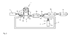
- FIG. 3 schematically shows the in FIG. 2 illustrated embodiment of the internal combustion engine 1 during operation in a first circuit state, which is why reference is otherwise made to FIG. 1 and 2.
- the same reference numerals have been used for the same components.
- the shut-off element 6a at the first branch 5a closes the first return line 5, so that the low-pressure EGR in the circuit state according to FIG. 3 is deactivated ie no exhaust gas is returned.
- the shut-off element 6b provided at the first junction 5b consequently only releases the suction line 4 and closes the first return line 5.
- FIG. 4 schematically shows the in FIG. 2 illustrated embodiment of the internal combustion engine 1 during operation in a second circuit state, which is why reference is otherwise made to FIG. 1 and 2.
- the same reference numerals have been used for the same components.
- the shut-off element 6a at the first branch 5a is in a middle position in which it releases both the exhaust pipe 3 leading to the second exhaust aftertreatment system 9b and the first return line 5.
- the shut-off element 6b provided at the first junction 5b releases the first return line 5 and closes the suction line 4.
- the low-pressure EGR activated ie basically via exhaust gas recirculation line 5 can be returned.
- air is introduced into the return line 5 by means of the device 7, which is why the shut-off element 8 releases the connection of the device 7 to the return line 5 and briefly blocks the exhaust gas flow in the return line 5.
- the internal combustion engine 1 or the compressor 2b therefore draws in diluted exhaust gas via the return line 5 and thus both exhaust gas and air.
- the suction line 4 is not needed in this case for supplying air and is closed.
- the gas streams, namely the exhaust stream, the air stream supplied for dilution, and the recirculated exhaust stream diluted with air are shown as dashed lines.
- FIG. 5 schematically shows the in FIG. 2 illustrated embodiment of the internal combustion engine 1 during operation in a third circuit state, which is why reference is otherwise made to FIG. 1 and 2.
- the same reference numerals have been used for the same components.
- shut-off element 6b at the first junction 5b - like the shut-off 6a at the first branch 5a - in a middle position so that an influx of both the suction line 4 and from the first return line 5 is possible.
- the internal combustion engine 1 is thus supplied in addition to the diluted exhaust gas from the return line 5 additional fresh air via intake 4.
- the gas streams namely the intake airflow, the exhaust gas flow, the airflow supplied for dilution, and the recirculated exhaust flow diluted with air are shown as dashed lines.
- FIG. 6 schematically shows a second embodiment of the internal combustion engine 1, which is in the present case out of operation. It should only the differences to the in FIG. 1 Otherwise, reference will be made to FIG. 1 , The same reference numerals have been used for the same components.
- a supply line 15 is provided, which branches off downstream of the device 7 for supplying air from the first line 5 for exhaust gas recirculation and opens into the intake line 4 upstream of the compressor 2b.
- a gas storage 13 is arranged, which serves for the storage of diluted exhaust gas.
- a pump 14 and downstream of the gas reservoir 13 are provided in the supply line 15 upstream of the gas reservoir 13, a pump 14 and downstream of the gas reservoir 13, a shut-off element 16 are provided.
- the pump 14 is used to promote the exhaust gas in the memory 13. With the shut-off 16, the gas storage 13 can be separated from the intake pipe 4 or connect with this.
- the gas reservoir 13 improves the response of the low-pressure EGR, because using the gas reservoir 13, even in the transient operation of the internal combustion engine 1, an increased amount of exhaust gas - can be provided quickly by direct removal from the gas storage 13.
- the operation of the gas storage 13 is in connection with the FIGS. 7 and 8th described, which the internal combustion engine 1 according to FIG. 6 show during operation.
- FIG. 7 schematically shows the in FIG. 6 illustrated, equipped with sensors 12 and in operation internal combustion engine 1 in a first circuit state.
- sensors 12 provided reference is made to the description of FIG. 2 ,
- shut-off element 6a at the first branch 5a present in a middle position in which it releases both the exhaust pipe 3, which leads to the second exhaust aftertreatment system 9b, and the first return line 5.
- shut-off element 6b provided at the first junction 5b closes the first return line 5 and only releases the suction line 4.
- the return line 5 is presently used for storing the gas storage 13.
- air is introduced into the return line 5 by means of the device 7 in order to dilute the exhaust gas supplied to the gas accumulator 13.
- the shut-off element 16 is closed, so that the gas accumulator 13 is separated from the intake line 4.
- the gas flows namely the air stream drawn in via intake line 4, the exhaust gas flow, the air flow supplied for dilution and the exhaust gas flow diluted with air into the gas reservoir 13, are shown as dashed lines.
- FIG. 8 schematically shows the in FIG. 6 illustrated, equipped with sensors 12 and in operation internal combustion engine 1 in a second circuit state.
- shut-off 16 is open downstream of the gas reservoir 13, so that the gas accumulator 13 is in communication with the intake manifold 4 and diluted exhaust gas flows from the memory 13 into the intake manifold 4.
- shut-off element 6b at the first junction 5b - like the shut-off element 6a at the first branch 5a - in a middle position so that an inflow from both the suction line 4 and from the first return line 5 is possible.
- the internal combustion engine 1 is thus supplied diluted exhaust gas from the return line 5 and fresh air via the intake passage 4.
- FIG. 9 schematically shows a third embodiment of the internal combustion engine 1, which is in the present case out of service. It should only the differences to the in FIG. 1 Otherwise, reference will be made to FIG. 1 , The same reference numerals have been used for the same components.
- FIG. 9 illustrated internal combustion engine 1 additionally equipped with a high-pressure EGR, in which the exhaust gas upstream of the turbine 2a and not - as in the low-pressure EGR - downstream of the turbine 2a is removed from the exhaust pipe 3 and downstream of the compressor 2b introduced back into the intake 4 becomes.
- a second line 17 for exhaust gas recirculation is provided, which branches off upstream of the turbine 2a from the exhaust pipe 3 to form a second branch 17a and opens downstream of the compressor 2b in the intake pipe 4 to form a second junction 17b.
- a throttle element 19 is provided in the intake line 4 in order to generate the pressure gradient required between the exhaust line 3 and the intake line 4 for the delivery.
- shut-off element 18 is used to set the return rate.
- FIG. 10 schematically shows a fourth embodiment of the internal combustion engine 1, which is in the present case out of operation. It should only the differences to the in FIG. 1 Otherwise, reference will be made to FIG. 1 , The same reference numerals have been used for the same components.
- the first line 5 goes to the return of exhaust gas into the intake 4 via ie the intake 4 is the Forst emotion the return line 5.
- Both line 4, 5 form a conduit downstream of the device 7 for supplying air, so that the internal combustion engine 1 air is supplied exclusively via the device 7 for supplying air.
Landscapes
- Engineering & Computer Science (AREA)
- Chemical & Material Sciences (AREA)
- Combustion & Propulsion (AREA)
- Mechanical Engineering (AREA)
- General Engineering & Computer Science (AREA)
- Exhaust-Gas Circulating Devices (AREA)
- Supercharger (AREA)
Priority Applications (2)
| Application Number | Priority Date | Filing Date | Title |
|---|---|---|---|
| EP08104882A EP2154355B1 (fr) | 2008-07-25 | 2008-07-25 | Moteur à combustion interne suralimenté avec recyclage des gaz d'échappement |
| CN2009201616566U CN201560837U (zh) | 2008-07-25 | 2009-07-15 | 具有排气再循环的增压内燃发动机 |
Applications Claiming Priority (1)
| Application Number | Priority Date | Filing Date | Title |
|---|---|---|---|
| EP08104882A EP2154355B1 (fr) | 2008-07-25 | 2008-07-25 | Moteur à combustion interne suralimenté avec recyclage des gaz d'échappement |
Publications (2)
| Publication Number | Publication Date |
|---|---|
| EP2154355A1 true EP2154355A1 (fr) | 2010-02-17 |
| EP2154355B1 EP2154355B1 (fr) | 2011-09-14 |
Family
ID=40010957
Family Applications (1)
| Application Number | Title | Priority Date | Filing Date |
|---|---|---|---|
| EP08104882A Ceased EP2154355B1 (fr) | 2008-07-25 | 2008-07-25 | Moteur à combustion interne suralimenté avec recyclage des gaz d'échappement |
Country Status (2)
| Country | Link |
|---|---|
| EP (1) | EP2154355B1 (fr) |
| CN (1) | CN201560837U (fr) |
Cited By (6)
| Publication number | Priority date | Publication date | Assignee | Title |
|---|---|---|---|---|
| DE102010056238A1 (de) * | 2010-12-24 | 2012-06-28 | Audi Ag | Antrieb mit einer Brennkraftmaschine und einer Expansionsmaschine mit Gasrückführung |
| WO2015141754A1 (fr) * | 2014-03-18 | 2015-09-24 | Toyota Jidosha Kabushiki Kaisha | Moteur à combustion interne |
| FR3041042A1 (fr) * | 2015-09-14 | 2017-03-17 | Continental Automotive France | Dispositif d'echappement d'un moteur a combustion interne comportant un compresseur electrique et un reservoir de gaz d'echappement comprimes |
| DE102015220923A1 (de) * | 2015-10-27 | 2017-04-27 | Ford Global Technologies, Llc | Aufgeladene Brennkraftmaschine mit Abgasrückführung umfassend einen Kühler |
| DE102011107250B4 (de) | 2010-07-23 | 2018-03-29 | GM Global Technology Operations LLC (n. d. Ges. d. Staates Delaware) | Abgasrückführungssystem für einen Verbrennungsmotor sowie Verbrennungsmotor mit solch einem Abgasrückführungssystem |
| DE102020130684A1 (de) | 2020-11-20 | 2022-05-25 | Bayerische Motoren Werke Aktiengesellschaft | Abgasanlage und Verfahren zur Abgasrückführung in einem Kraftfahrzeug und Kraftfahrzeug |
Families Citing this family (2)
| Publication number | Priority date | Publication date | Assignee | Title |
|---|---|---|---|---|
| KR101886095B1 (ko) * | 2016-08-04 | 2018-08-07 | 현대자동차 주식회사 | Egr 장치가 구비된 엔진 시스템 |
| CN114623024A (zh) * | 2021-03-09 | 2022-06-14 | 长城汽车股份有限公司 | 发动机、发动机的控制方法以及车辆 |
Citations (8)
| Publication number | Priority date | Publication date | Assignee | Title |
|---|---|---|---|---|
| DE9421145U1 (de) | 1994-04-28 | 1995-05-04 | Mtu Motoren- Und Turbinen-Union Friedrichshafen Gmbh, 88045 Friedrichshafen | Dieselbrennkraftmaschine mit in einer Abgasrückführleitung angeordnetem Wärmetauscher für die Abgaskühlung |
| WO1999015773A1 (fr) * | 1997-09-22 | 1999-04-01 | Turbodyne Systems, Inc. | Dispositif de recirculation des gaz d'echappement a action rapide |
| JPH1193781A (ja) * | 1997-09-19 | 1999-04-06 | Isuzu Motors Ltd | Egrクーラー付きegr装置 |
| DE10053675A1 (de) * | 2000-10-28 | 2002-05-08 | Volkswagen Ag | Brennkraftmaschine mit geregelter Abgasrückführung |
| EP1308614A1 (fr) * | 2001-10-31 | 2003-05-07 | Peugeot Citroen Automobiles SA | Système de motorisation pour véhicule |
| US20060021327A1 (en) * | 2004-07-30 | 2006-02-02 | Kiser Matthew T | Exhaust gas recirculation system having an electrostatic precipitator |
| WO2007062682A1 (fr) * | 2005-11-29 | 2007-06-07 | Renault Trucks | Systeme de recirculation des gaz d'echappement et procede de nettoyage d'un tel systeme |
| WO2007129160A1 (fr) * | 2006-04-26 | 2007-11-15 | Toyota Jidosha Kabushiki Kaisha | Appareil de recirculation des gaz d'échappement pour moteur à combustion interne et procédé de commande de l'appareil de recirculation des gaz d'échappement |
-
2008
- 2008-07-25 EP EP08104882A patent/EP2154355B1/fr not_active Ceased
-
2009
- 2009-07-15 CN CN2009201616566U patent/CN201560837U/zh not_active Expired - Lifetime
Patent Citations (8)
| Publication number | Priority date | Publication date | Assignee | Title |
|---|---|---|---|---|
| DE9421145U1 (de) | 1994-04-28 | 1995-05-04 | Mtu Motoren- Und Turbinen-Union Friedrichshafen Gmbh, 88045 Friedrichshafen | Dieselbrennkraftmaschine mit in einer Abgasrückführleitung angeordnetem Wärmetauscher für die Abgaskühlung |
| JPH1193781A (ja) * | 1997-09-19 | 1999-04-06 | Isuzu Motors Ltd | Egrクーラー付きegr装置 |
| WO1999015773A1 (fr) * | 1997-09-22 | 1999-04-01 | Turbodyne Systems, Inc. | Dispositif de recirculation des gaz d'echappement a action rapide |
| DE10053675A1 (de) * | 2000-10-28 | 2002-05-08 | Volkswagen Ag | Brennkraftmaschine mit geregelter Abgasrückführung |
| EP1308614A1 (fr) * | 2001-10-31 | 2003-05-07 | Peugeot Citroen Automobiles SA | Système de motorisation pour véhicule |
| US20060021327A1 (en) * | 2004-07-30 | 2006-02-02 | Kiser Matthew T | Exhaust gas recirculation system having an electrostatic precipitator |
| WO2007062682A1 (fr) * | 2005-11-29 | 2007-06-07 | Renault Trucks | Systeme de recirculation des gaz d'echappement et procede de nettoyage d'un tel systeme |
| WO2007129160A1 (fr) * | 2006-04-26 | 2007-11-15 | Toyota Jidosha Kabushiki Kaisha | Appareil de recirculation des gaz d'échappement pour moteur à combustion interne et procédé de commande de l'appareil de recirculation des gaz d'échappement |
Cited By (7)
| Publication number | Priority date | Publication date | Assignee | Title |
|---|---|---|---|---|
| DE102011107250B4 (de) | 2010-07-23 | 2018-03-29 | GM Global Technology Operations LLC (n. d. Ges. d. Staates Delaware) | Abgasrückführungssystem für einen Verbrennungsmotor sowie Verbrennungsmotor mit solch einem Abgasrückführungssystem |
| DE102010056238A1 (de) * | 2010-12-24 | 2012-06-28 | Audi Ag | Antrieb mit einer Brennkraftmaschine und einer Expansionsmaschine mit Gasrückführung |
| US9096116B2 (en) | 2010-12-24 | 2015-08-04 | Audi Ag | Drive with an internal combustion engine and an expansion machine with gas return |
| WO2015141754A1 (fr) * | 2014-03-18 | 2015-09-24 | Toyota Jidosha Kabushiki Kaisha | Moteur à combustion interne |
| FR3041042A1 (fr) * | 2015-09-14 | 2017-03-17 | Continental Automotive France | Dispositif d'echappement d'un moteur a combustion interne comportant un compresseur electrique et un reservoir de gaz d'echappement comprimes |
| DE102015220923A1 (de) * | 2015-10-27 | 2017-04-27 | Ford Global Technologies, Llc | Aufgeladene Brennkraftmaschine mit Abgasrückführung umfassend einen Kühler |
| DE102020130684A1 (de) | 2020-11-20 | 2022-05-25 | Bayerische Motoren Werke Aktiengesellschaft | Abgasanlage und Verfahren zur Abgasrückführung in einem Kraftfahrzeug und Kraftfahrzeug |
Also Published As
| Publication number | Publication date |
|---|---|
| EP2154355B1 (fr) | 2011-09-14 |
| CN201560837U (zh) | 2010-08-25 |
Similar Documents
| Publication | Publication Date | Title |
|---|---|---|
| EP2154355B1 (fr) | Moteur à combustion interne suralimenté avec recyclage des gaz d'échappement | |
| DE10112521B4 (de) | Dieselmotor | |
| DE102014201709B4 (de) | Abgasturboaufgeladene Brennkraftmaschine mit Abgasnachbehandlung und Verfahren zum Betreiben einer derartigen Brennkraftmaschine | |
| DE19914787C2 (de) | Abgasreinigungssystem für einen Verbrennungsmotor | |
| EP2183471B1 (fr) | Post-traitement de gaz d'echappement en amont d'un turbocompresseur | |
| DE102014201579A1 (de) | Brennkraftmaschine mit selektivem Katalysator zur Reduzierung der Stickoxide und Verfahren zum Betreiben einer derartigen Brennkraftmaschine | |
| EP2635777B1 (fr) | Moteur à combustion interne d'un véhicule automobile et procédé pour faire fonctionner un moteur à combustion interne d'un véhicule automobile | |
| EP1640597A1 (fr) | Moteur à combustion interne à suralimentation et procédé pour faire fonctionnner un tel moteur à combustion interne | |
| DE102008043487A1 (de) | Brennkraftmaschine mit Turbolader und Oxidationskatalysator | |
| DE102016212249B4 (de) | Zweistufig aufladbare direkteinspritzende Brennkraftmaschine mit Abgasnachbehandlung und Verfahren zum Betreiben einer derartigen Brennkraftmaschine | |
| DE102010060330A1 (de) | Verfahren zur Überwachung einer Schadstoffkonzentration im Abgas einer Brennkraftmaschine | |
| DE112007002869T5 (de) | Niederdruck EGR System mit Vollbereichstauglichkeit | |
| DE102010003337A1 (de) | Kraftfahrzeug mit Verbrennungsmotor sowie Verfahren zu dessen Betrieb | |
| DE102017111454A1 (de) | Ottomotor mit Partikelfilter und Verfahren zum Betreiben eines Ottomotors | |
| DE102015217394B4 (de) | Verfahren zur Steuerung eines Partikelfilters und Kraftfahrzeug | |
| DE102009020625A1 (de) | Verbrennungskraftmaschine | |
| DE102013008827A1 (de) | Aufgeladene Brennkraftmaschine | |
| DE102019005155A1 (de) | Verbrennungskraftmaschine für ein Kraftfahrzeug, insbesondere für einen Kraftwagen, sowie Verfahren zum Betreiben einer solchen Verbrennungskraftmaschine | |
| EP2058485A1 (fr) | Moteur à combustion interne chargé et procédé de fonctionnement d'un tel moteur à combustion interne | |
| DE102009051027B4 (de) | Antriebsaggregat mit einer Dieselbrennkraftmaschine und Abgasrückführung sowie Verfahren zum Betreiben eines solchen Antriebsaggregats | |
| DE102013202299A1 (de) | Brennkraftmaschine mit selektivem Katalysator zur Reduzierung der Stickoxide und Verfahren zum Betreiben einer derartigen Brennkraftmaschine | |
| DE102018120179B4 (de) | Abgastrakt für eine Verbrennungskraftmaschine und Verbrennungskraftmaschine | |
| DE102015220039A1 (de) | Betriebsverfahren und Kraftfahrzeug | |
| DE202015102241U1 (de) | Zweistufig aufladbare Brennkraftmaschine mit Abgasnachbehandlung | |
| DE102008013254B4 (de) | Verfahren zum Betreiben einer Brennkraftmaschine mit Abgasrückführung |
Legal Events
| Date | Code | Title | Description |
|---|---|---|---|
| PUAI | Public reference made under article 153(3) epc to a published international application that has entered the european phase |
Free format text: ORIGINAL CODE: 0009012 |
|
| AK | Designated contracting states |
Kind code of ref document: A1 Designated state(s): AT BE BG CH CY CZ DE DK EE ES FI FR GB GR HR HU IE IS IT LI LT LU LV MC MT NL NO PL PT RO SE SI SK TR |
|
| AX | Request for extension of the european patent |
Extension state: AL BA MK RS |
|
| 17P | Request for examination filed |
Effective date: 20100817 |
|
| AKX | Designation fees paid |
Designated state(s): DE FR GB |
|
| RTI1 | Title (correction) |
Free format text: CHARGED INTERNAL COMBUSTION ENGINE WITH EXHAUST GAS RECIRCULATION |
|
| GRAP | Despatch of communication of intention to grant a patent |
Free format text: ORIGINAL CODE: EPIDOSNIGR1 |
|
| GRAS | Grant fee paid |
Free format text: ORIGINAL CODE: EPIDOSNIGR3 |
|
| GRAA | (expected) grant |
Free format text: ORIGINAL CODE: 0009210 |
|
| AK | Designated contracting states |
Kind code of ref document: B1 Designated state(s): DE FR GB |
|
| REG | Reference to a national code |
Ref country code: GB Ref legal event code: FG4D Free format text: NOT ENGLISH |
|
| REG | Reference to a national code |
Ref country code: DE Ref legal event code: R096 Ref document number: 502008004853 Country of ref document: DE Effective date: 20111110 |
|
| PLBE | No opposition filed within time limit |
Free format text: ORIGINAL CODE: 0009261 |
|
| STAA | Information on the status of an ep patent application or granted ep patent |
Free format text: STATUS: NO OPPOSITION FILED WITHIN TIME LIMIT |
|
| 26N | No opposition filed |
Effective date: 20120615 |
|
| REG | Reference to a national code |
Ref country code: DE Ref legal event code: R097 Ref document number: 502008004853 Country of ref document: DE Effective date: 20120615 |
|
| REG | Reference to a national code |
Ref country code: FR Ref legal event code: PLFP Year of fee payment: 9 |
|
| REG | Reference to a national code |
Ref country code: FR Ref legal event code: PLFP Year of fee payment: 10 |
|
| REG | Reference to a national code |
Ref country code: FR Ref legal event code: PLFP Year of fee payment: 11 |
|
| PGFP | Annual fee paid to national office [announced via postgrant information from national office to epo] |
Ref country code: FR Payment date: 20190621 Year of fee payment: 12 |
|
| PGFP | Annual fee paid to national office [announced via postgrant information from national office to epo] |
Ref country code: GB Payment date: 20190626 Year of fee payment: 12 |
|
| GBPC | Gb: european patent ceased through non-payment of renewal fee |
Effective date: 20200725 |
|
| PG25 | Lapsed in a contracting state [announced via postgrant information from national office to epo] |
Ref country code: FR Free format text: LAPSE BECAUSE OF NON-PAYMENT OF DUE FEES Effective date: 20200731 Ref country code: GB Free format text: LAPSE BECAUSE OF NON-PAYMENT OF DUE FEES Effective date: 20200725 |
|
| PGFP | Annual fee paid to national office [announced via postgrant information from national office to epo] |
Ref country code: DE Payment date: 20220615 Year of fee payment: 15 |
|
| P01 | Opt-out of the competence of the unified patent court (upc) registered |
Effective date: 20230620 |
|
| REG | Reference to a national code |
Ref country code: DE Ref legal event code: R119 Ref document number: 502008004853 Country of ref document: DE |
|
| PG25 | Lapsed in a contracting state [announced via postgrant information from national office to epo] |
Ref country code: DE Free format text: LAPSE BECAUSE OF NON-PAYMENT OF DUE FEES Effective date: 20240201 |