EP2154355A1 - Charged internal combustion engine with exhaust gas recirculation and method to operate such an internal combustion engine - Google Patents
Charged internal combustion engine with exhaust gas recirculation and method to operate such an internal combustion engine Download PDFInfo
- Publication number
- EP2154355A1 EP2154355A1 EP08104882A EP08104882A EP2154355A1 EP 2154355 A1 EP2154355 A1 EP 2154355A1 EP 08104882 A EP08104882 A EP 08104882A EP 08104882 A EP08104882 A EP 08104882A EP 2154355 A1 EP2154355 A1 EP 2154355A1
- Authority
- EP
- European Patent Office
- Prior art keywords
- exhaust gas
- internal combustion
- combustion engine
- line
- exhaust
- Prior art date
- Legal status (The legal status is an assumption and is not a legal conclusion. Google has not performed a legal analysis and makes no representation as to the accuracy of the status listed.)
- Granted
Links
- 238000002485 combustion reaction Methods 0.000 title claims abstract description 105
- 238000000034 method Methods 0.000 title claims abstract description 11
- 239000007789 gas Substances 0.000 claims abstract description 186
- 239000000203 mixture Substances 0.000 claims abstract description 5
- 238000011144 upstream manufacturing Methods 0.000 claims description 25
- 239000000567 combustion gas Substances 0.000 claims description 5
- 238000007599 discharging Methods 0.000 claims description 4
- UGFAIRIUMAVXCW-UHFFFAOYSA-N Carbon monoxide Chemical compound [O+]#[C-] UGFAIRIUMAVXCW-UHFFFAOYSA-N 0.000 abstract description 5
- 230000015572 biosynthetic process Effects 0.000 abstract description 3
- 239000003546 flue gas Substances 0.000 abstract 1
- MWUXSHHQAYIFBG-UHFFFAOYSA-N Nitric oxide Chemical compound O=[N] MWUXSHHQAYIFBG-UHFFFAOYSA-N 0.000 description 39
- 229930195733 hydrocarbon Natural products 0.000 description 11
- 150000002430 hydrocarbons Chemical class 0.000 description 11
- 239000000446 fuel Substances 0.000 description 7
- 239000002245 particle Substances 0.000 description 7
- 239000004071 soot Substances 0.000 description 7
- 230000004044 response Effects 0.000 description 5
- 229910002091 carbon monoxide Inorganic materials 0.000 description 4
- 239000003054 catalyst Substances 0.000 description 4
- 230000003197 catalytic effect Effects 0.000 description 4
- 230000007423 decrease Effects 0.000 description 4
- 238000009833 condensation Methods 0.000 description 3
- 230000005494 condensation Effects 0.000 description 3
- 230000003247 decreasing effect Effects 0.000 description 3
- 238000010790 dilution Methods 0.000 description 3
- 239000012895 dilution Substances 0.000 description 3
- 239000003344 environmental pollutant Substances 0.000 description 3
- 230000003647 oxidation Effects 0.000 description 3
- 238000007254 oxidation reaction Methods 0.000 description 3
- 239000012071 phase Substances 0.000 description 3
- 231100000719 pollutant Toxicity 0.000 description 3
- 230000001052 transient effect Effects 0.000 description 3
- QGZKDVFQNNGYKY-UHFFFAOYSA-N Ammonia Chemical compound N QGZKDVFQNNGYKY-UHFFFAOYSA-N 0.000 description 2
- CURLTUGMZLYLDI-UHFFFAOYSA-N Carbon dioxide Chemical compound O=C=O CURLTUGMZLYLDI-UHFFFAOYSA-N 0.000 description 2
- 239000003638 chemical reducing agent Substances 0.000 description 2
- 238000001514 detection method Methods 0.000 description 2
- 238000006073 displacement reaction Methods 0.000 description 2
- 239000007791 liquid phase Substances 0.000 description 2
- 230000008569 process Effects 0.000 description 2
- 230000009467 reduction Effects 0.000 description 2
- 230000008929 regeneration Effects 0.000 description 2
- 238000011069 regeneration method Methods 0.000 description 2
- XLYOFNOQVPJJNP-UHFFFAOYSA-N water Substances O XLYOFNOQVPJJNP-UHFFFAOYSA-N 0.000 description 2
- 239000004215 Carbon black (E152) Substances 0.000 description 1
- 206010021143 Hypoxia Diseases 0.000 description 1
- XSQUKJJJFZCRTK-UHFFFAOYSA-N Urea Chemical compound NC(N)=O XSQUKJJJFZCRTK-UHFFFAOYSA-N 0.000 description 1
- 229910021529 ammonia Inorganic materials 0.000 description 1
- QVGXLLKOCUKJST-UHFFFAOYSA-N atomic oxygen Chemical compound [O] QVGXLLKOCUKJST-UHFFFAOYSA-N 0.000 description 1
- 230000008901 benefit Effects 0.000 description 1
- 239000004202 carbamide Substances 0.000 description 1
- 229910002092 carbon dioxide Inorganic materials 0.000 description 1
- 239000001569 carbon dioxide Substances 0.000 description 1
- 230000008859 change Effects 0.000 description 1
- 238000006243 chemical reaction Methods 0.000 description 1
- 238000004891 communication Methods 0.000 description 1
- 238000001816 cooling Methods 0.000 description 1
- 238000011161 development Methods 0.000 description 1
- 230000018109 developmental process Effects 0.000 description 1
- 238000007865 diluting Methods 0.000 description 1
- 238000005516 engineering process Methods 0.000 description 1
- 239000007792 gaseous phase Substances 0.000 description 1
- 239000012535 impurity Substances 0.000 description 1
- 230000004941 influx Effects 0.000 description 1
- 239000000463 material Substances 0.000 description 1
- 238000005259 measurement Methods 0.000 description 1
- 239000001301 oxygen Substances 0.000 description 1
- 229910052760 oxygen Inorganic materials 0.000 description 1
- 238000000746 purification Methods 0.000 description 1
- 230000001172 regenerating effect Effects 0.000 description 1
- 230000003584 silencer Effects 0.000 description 1
- 238000012360 testing method Methods 0.000 description 1
Images


Classifications
-
- F—MECHANICAL ENGINEERING; LIGHTING; HEATING; WEAPONS; BLASTING
- F01—MACHINES OR ENGINES IN GENERAL; ENGINE PLANTS IN GENERAL; STEAM ENGINES
- F01N—GAS-FLOW SILENCERS OR EXHAUST APPARATUS FOR MACHINES OR ENGINES IN GENERAL; GAS-FLOW SILENCERS OR EXHAUST APPARATUS FOR INTERNAL COMBUSTION ENGINES
- F01N13/00—Exhaust or silencing apparatus characterised by constructional features ; Exhaust or silencing apparatus, or parts thereof, having pertinent characteristics not provided for in, or of interest apart from, groups F01N1/00 - F01N5/00, F01N9/00, F01N11/00
- F01N13/009—Exhaust or silencing apparatus characterised by constructional features ; Exhaust or silencing apparatus, or parts thereof, having pertinent characteristics not provided for in, or of interest apart from, groups F01N1/00 - F01N5/00, F01N9/00, F01N11/00 having two or more separate purifying devices arranged in series
-
- F—MECHANICAL ENGINEERING; LIGHTING; HEATING; WEAPONS; BLASTING
- F02—COMBUSTION ENGINES; HOT-GAS OR COMBUSTION-PRODUCT ENGINE PLANTS
- F02D—CONTROLLING COMBUSTION ENGINES
- F02D21/00—Controlling engines characterised by their being supplied with non-airborne oxygen or other non-fuel gas
- F02D21/06—Controlling engines characterised by their being supplied with non-airborne oxygen or other non-fuel gas peculiar to engines having other non-fuel gas added to combustion air
- F02D21/08—Controlling engines characterised by their being supplied with non-airborne oxygen or other non-fuel gas peculiar to engines having other non-fuel gas added to combustion air the other gas being the exhaust gas of engine
-
- F—MECHANICAL ENGINEERING; LIGHTING; HEATING; WEAPONS; BLASTING
- F02—COMBUSTION ENGINES; HOT-GAS OR COMBUSTION-PRODUCT ENGINE PLANTS
- F02D—CONTROLLING COMBUSTION ENGINES
- F02D41/00—Electrical control of supply of combustible mixture or its constituents
- F02D41/0002—Controlling intake air
- F02D41/0007—Controlling intake air for control of turbo-charged or super-charged engines
-
- F—MECHANICAL ENGINEERING; LIGHTING; HEATING; WEAPONS; BLASTING
- F02—COMBUSTION ENGINES; HOT-GAS OR COMBUSTION-PRODUCT ENGINE PLANTS
- F02D—CONTROLLING COMBUSTION ENGINES
- F02D41/00—Electrical control of supply of combustible mixture or its constituents
- F02D41/0025—Controlling engines characterised by use of non-liquid fuels, pluralities of fuels, or non-fuel substances added to the combustible mixtures
- F02D41/0047—Controlling exhaust gas recirculation [EGR]
- F02D41/0065—Specific aspects of external EGR control
-
- F—MECHANICAL ENGINEERING; LIGHTING; HEATING; WEAPONS; BLASTING
- F02—COMBUSTION ENGINES; HOT-GAS OR COMBUSTION-PRODUCT ENGINE PLANTS
- F02M—SUPPLYING COMBUSTION ENGINES IN GENERAL WITH COMBUSTIBLE MIXTURES OR CONSTITUENTS THEREOF
- F02M26/00—Engine-pertinent apparatus for adding exhaust gases to combustion-air, main fuel or fuel-air mixture, e.g. by exhaust gas recirculation [EGR] systems
- F02M26/02—EGR systems specially adapted for supercharged engines
- F02M26/04—EGR systems specially adapted for supercharged engines with a single turbocharger
- F02M26/06—Low pressure loops, i.e. wherein recirculated exhaust gas is taken out from the exhaust downstream of the turbocharger turbine and reintroduced into the intake system upstream of the compressor
-
- F—MECHANICAL ENGINEERING; LIGHTING; HEATING; WEAPONS; BLASTING
- F02—COMBUSTION ENGINES; HOT-GAS OR COMBUSTION-PRODUCT ENGINE PLANTS
- F02M—SUPPLYING COMBUSTION ENGINES IN GENERAL WITH COMBUSTIBLE MIXTURES OR CONSTITUENTS THEREOF
- F02M26/00—Engine-pertinent apparatus for adding exhaust gases to combustion-air, main fuel or fuel-air mixture, e.g. by exhaust gas recirculation [EGR] systems
- F02M26/13—Arrangement or layout of EGR passages, e.g. in relation to specific engine parts or for incorporation of accessories
- F02M26/34—Arrangement or layout of EGR passages, e.g. in relation to specific engine parts or for incorporation of accessories with compressors, turbines or the like in the recirculation passage
-
- F—MECHANICAL ENGINEERING; LIGHTING; HEATING; WEAPONS; BLASTING
- F02—COMBUSTION ENGINES; HOT-GAS OR COMBUSTION-PRODUCT ENGINE PLANTS
- F02M—SUPPLYING COMBUSTION ENGINES IN GENERAL WITH COMBUSTIBLE MIXTURES OR CONSTITUENTS THEREOF
- F02M26/00—Engine-pertinent apparatus for adding exhaust gases to combustion-air, main fuel or fuel-air mixture, e.g. by exhaust gas recirculation [EGR] systems
- F02M26/13—Arrangement or layout of EGR passages, e.g. in relation to specific engine parts or for incorporation of accessories
- F02M26/36—Arrangement or layout of EGR passages, e.g. in relation to specific engine parts or for incorporation of accessories with means for adding fluids other than exhaust gas to the recirculation passage; with reformers
-
- F—MECHANICAL ENGINEERING; LIGHTING; HEATING; WEAPONS; BLASTING
- F02—COMBUSTION ENGINES; HOT-GAS OR COMBUSTION-PRODUCT ENGINE PLANTS
- F02M—SUPPLYING COMBUSTION ENGINES IN GENERAL WITH COMBUSTIBLE MIXTURES OR CONSTITUENTS THEREOF
- F02M26/00—Engine-pertinent apparatus for adding exhaust gases to combustion-air, main fuel or fuel-air mixture, e.g. by exhaust gas recirculation [EGR] systems
- F02M26/13—Arrangement or layout of EGR passages, e.g. in relation to specific engine parts or for incorporation of accessories
- F02M26/37—Arrangement or layout of EGR passages, e.g. in relation to specific engine parts or for incorporation of accessories with temporary storage of recirculated exhaust gas
-
- F—MECHANICAL ENGINEERING; LIGHTING; HEATING; WEAPONS; BLASTING
- F01—MACHINES OR ENGINES IN GENERAL; ENGINE PLANTS IN GENERAL; STEAM ENGINES
- F01N—GAS-FLOW SILENCERS OR EXHAUST APPARATUS FOR MACHINES OR ENGINES IN GENERAL; GAS-FLOW SILENCERS OR EXHAUST APPARATUS FOR INTERNAL COMBUSTION ENGINES
- F01N2240/00—Combination or association of two or more different exhaust treating devices, or of at least one such device with an auxiliary device, not covered by indexing codes F01N2230/00 or F01N2250/00, one of the devices being
- F01N2240/36—Combination or association of two or more different exhaust treating devices, or of at least one such device with an auxiliary device, not covered by indexing codes F01N2230/00 or F01N2250/00, one of the devices being an exhaust flap
-
- F—MECHANICAL ENGINEERING; LIGHTING; HEATING; WEAPONS; BLASTING
- F02—COMBUSTION ENGINES; HOT-GAS OR COMBUSTION-PRODUCT ENGINE PLANTS
- F02B—INTERNAL-COMBUSTION PISTON ENGINES; COMBUSTION ENGINES IN GENERAL
- F02B37/00—Engines characterised by provision of pumps driven at least for part of the time by exhaust
-
- F—MECHANICAL ENGINEERING; LIGHTING; HEATING; WEAPONS; BLASTING
- F02—COMBUSTION ENGINES; HOT-GAS OR COMBUSTION-PRODUCT ENGINE PLANTS
- F02M—SUPPLYING COMBUSTION ENGINES IN GENERAL WITH COMBUSTIBLE MIXTURES OR CONSTITUENTS THEREOF
- F02M26/00—Engine-pertinent apparatus for adding exhaust gases to combustion-air, main fuel or fuel-air mixture, e.g. by exhaust gas recirculation [EGR] systems
- F02M26/02—EGR systems specially adapted for supercharged engines
- F02M26/04—EGR systems specially adapted for supercharged engines with a single turbocharger
- F02M26/05—High pressure loops, i.e. wherein recirculated exhaust gas is taken out from the exhaust system upstream of the turbine and reintroduced into the intake system downstream of the compressor
-
- F—MECHANICAL ENGINEERING; LIGHTING; HEATING; WEAPONS; BLASTING
- F02—COMBUSTION ENGINES; HOT-GAS OR COMBUSTION-PRODUCT ENGINE PLANTS
- F02M—SUPPLYING COMBUSTION ENGINES IN GENERAL WITH COMBUSTIBLE MIXTURES OR CONSTITUENTS THEREOF
- F02M26/00—Engine-pertinent apparatus for adding exhaust gases to combustion-air, main fuel or fuel-air mixture, e.g. by exhaust gas recirculation [EGR] systems
- F02M26/02—EGR systems specially adapted for supercharged engines
- F02M26/08—EGR systems specially adapted for supercharged engines for engines having two or more intake charge compressors or exhaust gas turbines, e.g. a turbocharger combined with an additional compressor
-
- F—MECHANICAL ENGINEERING; LIGHTING; HEATING; WEAPONS; BLASTING
- F02—COMBUSTION ENGINES; HOT-GAS OR COMBUSTION-PRODUCT ENGINE PLANTS
- F02M—SUPPLYING COMBUSTION ENGINES IN GENERAL WITH COMBUSTIBLE MIXTURES OR CONSTITUENTS THEREOF
- F02M26/00—Engine-pertinent apparatus for adding exhaust gases to combustion-air, main fuel or fuel-air mixture, e.g. by exhaust gas recirculation [EGR] systems
- F02M26/02—EGR systems specially adapted for supercharged engines
- F02M26/09—Constructional details, e.g. structural combinations of EGR systems and supercharger systems; Arrangement of the EGR and supercharger systems with respect to the engine
- F02M26/10—Constructional details, e.g. structural combinations of EGR systems and supercharger systems; Arrangement of the EGR and supercharger systems with respect to the engine having means to increase the pressure difference between the exhaust and intake system, e.g. venturis, variable geometry turbines, check valves using pressure pulsations or throttles in the air intake or exhaust system
-
- F—MECHANICAL ENGINEERING; LIGHTING; HEATING; WEAPONS; BLASTING
- F02—COMBUSTION ENGINES; HOT-GAS OR COMBUSTION-PRODUCT ENGINE PLANTS
- F02M—SUPPLYING COMBUSTION ENGINES IN GENERAL WITH COMBUSTIBLE MIXTURES OR CONSTITUENTS THEREOF
- F02M26/00—Engine-pertinent apparatus for adding exhaust gases to combustion-air, main fuel or fuel-air mixture, e.g. by exhaust gas recirculation [EGR] systems
- F02M26/13—Arrangement or layout of EGR passages, e.g. in relation to specific engine parts or for incorporation of accessories
- F02M26/35—Arrangement or layout of EGR passages, e.g. in relation to specific engine parts or for incorporation of accessories with means for cleaning or treating the recirculated gases, e.g. catalysts, condensate traps, particle filters or heaters
-
- Y—GENERAL TAGGING OF NEW TECHNOLOGICAL DEVELOPMENTS; GENERAL TAGGING OF CROSS-SECTIONAL TECHNOLOGIES SPANNING OVER SEVERAL SECTIONS OF THE IPC; TECHNICAL SUBJECTS COVERED BY FORMER USPC CROSS-REFERENCE ART COLLECTIONS [XRACs] AND DIGESTS
- Y02—TECHNOLOGIES OR APPLICATIONS FOR MITIGATION OR ADAPTATION AGAINST CLIMATE CHANGE
- Y02T—CLIMATE CHANGE MITIGATION TECHNOLOGIES RELATED TO TRANSPORTATION
- Y02T10/00—Road transport of goods or passengers
- Y02T10/10—Internal combustion engine [ICE] based vehicles
- Y02T10/12—Improving ICE efficiencies
-
- Y—GENERAL TAGGING OF NEW TECHNOLOGICAL DEVELOPMENTS; GENERAL TAGGING OF CROSS-SECTIONAL TECHNOLOGIES SPANNING OVER SEVERAL SECTIONS OF THE IPC; TECHNICAL SUBJECTS COVERED BY FORMER USPC CROSS-REFERENCE ART COLLECTIONS [XRACs] AND DIGESTS
- Y02—TECHNOLOGIES OR APPLICATIONS FOR MITIGATION OR ADAPTATION AGAINST CLIMATE CHANGE
- Y02T—CLIMATE CHANGE MITIGATION TECHNOLOGIES RELATED TO TRANSPORTATION
- Y02T10/00—Road transport of goods or passengers
- Y02T10/10—Internal combustion engine [ICE] based vehicles
- Y02T10/40—Engine management systems
Abstract
Description
Die Erfindung betrifft eine aufgeladene Brennkraftmaschine mit mindestens einem Zylinder, mindestens einer Abgasleitung zum Abführen der Verbrennungsgase aus diesem mindestens einen Zylinder und mindestens einer Ansaugleitung zum Zuführen von Frischluft bzw. Frischgemisch in diesen mindestens einen Zylinder, die mit mindestens einem Abgasturbolader ausgestattet ist, wobei
- ■ eine Turbine des mindestens einen Abgasturboladers in der mindestens einen Abgasleitung angeordnet ist und ein zu dieser Turbine zugehöriger Verdichter des mindestens einen Abgasturboladers in der mindestens einen Ansaugleitung angeordnet ist, und
- ■ eine erste Leitung zur Abgasrückführung vorgesehen ist, die stromabwärts der Turbine aus der mindestens einen Abgasleitung unter Ausbildung einer ersten Abzweigung abzweigt und stromaufwärts des Verdichters in die mindestens eine Ansaugleitung unter Ausbildung einer ersten Einmündung einmündet.
- A turbine of the at least one exhaust gas turbocharger is arranged in the at least one exhaust gas line and a compressor belonging to this turbine of the at least one exhaust gas turbocharger is arranged in the at least one intake line, and
- ■ A first line for exhaust gas recirculation is provided, which branches off downstream of the turbine from the at least one exhaust pipe to form a first branch and opens upstream of the compressor in the at least one suction line to form a first junction.
Des Weiteren betrifft die Erfindung ein Verfahren zum Betreiben einer aufgeladenen Brennkraftmaschine der oben genannten Art.Furthermore, the invention relates to a method for operating a supercharged internal combustion engine of the type mentioned above.
Im Rahmen der vorliegenden Erfindung umfaßt der Begriff Brennkraftmaschine Dieselmotoren und Ottomotoren, aber auch Hybrid-Brennkraftmaschinen.In the context of the present invention, the term internal combustion engine includes diesel engines and gasoline engines, but also hybrid internal combustion engines.
Die Aufladung von Brennkraftmaschinen gewinnt zunehmend an Bedeutung. In der Regel wird für die Aufladung ein Abgasturbolader eingesetzt, bei dem ein Verdichter und eine Turbine auf derselben Welle angeordnet sind, wobei der heiße Abgasstrom via Abgasleitung der Turbine zugeführt wird und sich unter Energieabgabe in dieser Turbine entspannt, wodurch die Welle in Drehung versetzt wird. Die vom Abgasstrom an die Turbine und schließlich an die Welle abgegebene Energie wird für den Antrieb des ebenfalls auf der Welle angeordneten Verdichters genutzt. Der Verdichter fördert und komprimiert die ihm via Ansaugleitung zugeführte Ladeluft, wodurch eine Aufladung des mindestens einen Zylinders erreicht wird.The charging of internal combustion engines is becoming increasingly important. As a rule, an exhaust gas turbocharger is used for the supercharging, in which a compressor and a turbine are arranged on the same shaft, wherein the hot exhaust gas flow is supplied via the exhaust pipe of the turbine and relaxes with energy release in this turbine, whereby the shaft is rotated , The energy emitted by the exhaust gas flow to the turbine and finally to the shaft is used to drive the compressor, which is also arranged on the shaft. The compressor conveys and compresses it via Intake line supplied charge air, whereby a charge of the at least one cylinder is achieved.
Häufig wird eine Ladeluftkühlung vorgesehen, mit der die komprimierte Verbrennungsluft vor Eintritt in den Brennraum d.h. den mindestens einen Zylinder gekühlt wird.Often a charge air cooling is provided, with which the compressed combustion air before entering the combustion chamber. the at least one cylinder is cooled.
Die Aufladung dient in erster Linie der Leistungssteigerung der Brennkraftmaschine. Die für den Verbrennungsprozeß benötigte Luft wird dabei verdichtet, wodurch jedem Zylinder pro Arbeitsspiel eine größere Luftmasse zugeführt werden kann. Dadurch können die Kraftstoffmasse und damit der Mitteldruck pme gesteigert werden.The charge is used primarily to increase the performance of the internal combustion engine. The air required for the combustion process is compressed, whereby each cylinder per cycle can be supplied with a larger air mass. As a result, the fuel mass and thus the mean pressure p me can be increased.
Schwierigkeiten bereitet die Auslegung des Abgasturboladers, wobei grundsätzlich eine spürbare Leistungssteigerung in allen Drehzahlbereichen angestrebt wird. Nach dem Stand der Technik wird aber ein starker Drehmomentabfall bei Unterschreiten einer bestimmten Drehzahl beobachtet. Verständlich wird dieser Drehmomentabfall, wenn berücksichtigt wird, dass das Ladedruckverhältnis vom Turbinendruckverhältnis abhängt. Wird beispielsweise bei einem Dieselmotor die Motorendrehzahl verringert, führt dies zu einem kleineren Abgasmassenstrom und damit zu einem kleineren Turbinendruckverhältnis. Dies hat zur Folge, dass zu niedrigeren Drehzahlen hin das Ladedruckverhältnis ebenfalls abnimmt, was gleichbedeutend ist mit einem Drehmomentabfall.The interpretation of the exhaust gas turbocharger is difficult, with basically a noticeable increase in performance in all speed ranges is sought. In the prior art, however, a strong torque drop is observed when falling below a certain speed. This torque drop becomes understandable if it is taken into account that the boost pressure ratio depends on the turbine pressure ratio. For example, if the engine speed is reduced in a diesel engine, this leads to a smaller exhaust gas mass flow and thus to a smaller turbine pressure ratio. As a result, at lower speeds, the boost pressure ratio also decreases, which is equivalent to a torque drop.
Grundsätzlich kann dabei dem Abfall des Ladedruckes durch eine Verkleinerung des Turbinenquerschnittes und der damit einhergehenden Steigerung des Turbinendruckverhältnisses entgegengewirkt werden, was aber zu Nachteilen bei hohen Drehzahlen führt.In principle, it is possible to counteract the drop in boost pressure by reducing the size of the turbine cross section and the associated increase in the turbine pressure ratio, but this leads to disadvantages at high rotational speeds.
In der Praxis werden daher auch häufig zwei oder mehrere Abgasturbolader eingesetzt, deren Turbinen parallel und/oder in Reihe geschaltet sind. Die Verdichter können dabei ebenfalls in Reihe und/oder parallel angeordnet werden. Zur Verbesserung der Drehmomentcharakteristik einer Brennkraftmaschine kann eine Abgasturboaufladung auch in Kombination mit einem Kompressor bzw. mechanischen Lader eingesetzt werden. Aus den genannten Gründen ist im Rahmen der vorliegenden Erfindung von mindestens einem Abgasturbolader die Rede.In practice, therefore, often two or more exhaust gas turbochargers are used, the turbines are connected in parallel and / or in series. The compressors can also be arranged in series and / or parallel. To improve the torque characteristic of an internal combustion engine, an exhaust gas turbocharging can also be used in combination with a compressor or mechanical supercharger. For the reasons mentioned is in the context of the present invention of at least one exhaust gas turbocharger.
Die Aufladung ist ein geeignetes Mittel, bei unverändertem Hubraum die Leistung einer Brennkraftmaschine zu steigern, oder bei gleicher Leistung den Hubraum zu reduzieren. In jedem Fall führt die Aufladung zu einer Erhöhung der Bauraumleistung und einer günstigeren Leistungsmasse. Bei gleichen Fahrzeugrandbedingungen läßt sich so das Lastkollektiv zu höheren Lasten hin verschieben, wo der spezifische Kraftstoffverbrauch niedriger ist. Letzteres wird auch als Downsizing bezeichnet.The charge is a suitable means to increase the capacity of an internal combustion engine with unchanged displacement, or to reduce the displacement at the same power. In any case, the charging leads to an increase in space performance and a lower power mass. At the same vehicle boundary conditions, the load collective can thus be shifted to higher loads, where the specific fuel consumption is lower. The latter is also referred to as downsizing.
Die Aufladung unterstützt folglich das ständige Bemühen in der Entwicklung von Brennkraftmaschinen, den Kraftstoffverbrauch zu minimieren d. h. den Wirkungsgrad der Brennkraftmaschine zu verbessern.Charging thus supports the constant effort in the development of internal combustion engines to minimize fuel consumption. D. H. to improve the efficiency of the internal combustion engine.
Mittels Aufladung können beim Dieselmotor die Stickoxidemissionen ohne Einbußen beim Wirkungsgrad verringert werden. Gleichzeitig können die Kohlenwasserstoffemissionen günstig beeinflußt werden. Die Emissionen an Kohlendioxid, die direkt mit dem Kraftstoffverbrauch korrelieren, nehmen mit sinkendem Kraftstoffverbrauch ebenfalls ab.By charging the nitrogen oxide emissions can be reduced without sacrificing efficiency in the diesel engine. At the same time, the hydrocarbon emissions can be favorably influenced. The emissions of carbon dioxide, which correlate directly with fuel consumption, also decrease with decreasing fuel consumption.
Die Aufladung eignet sich daher ebenfalls zur Reduzierung der Schadstoffemissionen. Um die zukünftigen Grenzwerte für Schadstoffemissionen einzuhalten, sind aber darüber hinaus weitere Maßnahmen erforderlich.The charge is therefore also suitable for reducing pollutant emissions. In order to meet the future limits for pollutant emissions, but further measures are also required.
Im Focus steht dabei unter anderem die Reduzierung der Stickoxidemissionen, die insbesondere bei den Dieselmotoren von hoher Relevanz sind. Da die Bildung der Stickoxide nicht nur einen Luftüberschuß, sondern auch hohe Temperaturen erfordert, besteht ein Konzept zur Verringerung der Stickoxidemissionen darin, die Verbrennungstemperaturen zu senken.Among other things, the focus is on reducing nitrogen oxide emissions, which are of particular relevance to diesel engines. Since the formation of nitrogen oxides requires not only an excess of air but also high temperatures, a concept for reducing nitrogen oxide emissions is to lower the combustion temperatures.
Dabei ist die Abgasrückführung d. h. die Rückführung von Verbrennungsgasen aus der Abgasleitung in die Ansaugleitung zielführend, bei der mit zunehmender Abgasrückführrate die Stickoxidemissionen deutlich gesenkt werden können. Die Abgasrückführrate xAGR bestimmt sich dabei wie folgt: 
wobei mAGR die Masse an zurückgeführtem Abgas und mFrischluft die zugeführte - gegebenenfalls durch einen Verdichter geführte und komprimierte - Frischluft bzw. Verbrennungsluft bezeichnet.In this case, the exhaust gas recirculation ie the return of combustion gases from the exhaust pipe in the intake line is expedient in which with increasing exhaust gas recirculation rate, the nitrogen oxide emissions can be significantly reduced. The exhaust gas recirculation rate x EGR is determined as follows:
wherein m AGR refers to the mass of recirculated exhaust gas and m fresh air, the supplied - optionally guided by a compressor and compressed - fresh air or combustion air.
Die Abgasrückführung eignet sich auch zur Reduzierung der Emissionen an unverbrannten Kohlenwasserstoffen im Teillastbereich.Exhaust gas recirculation is also suitable for reducing emissions of unburned hydrocarbons in the partial load range.
Um eine deutliche Senkung der Stickoxidemissionen zu erreichen, sind hohe Abgasrückführraten erforderlich, die in der Größenordnung von xAGR ≈ 60% bis 70% liegen können.In order to achieve a significant reduction in nitrogen oxide emissions, high exhaust gas recirculation rates are required, which can be on the order of x EGR ≈ 60% to 70%.
Dadurch ergibt sich aber ein Konflikt beim Betrieb einer Brennkraftmaschine mit Abgasturboaufladung und gleichzeitiger Verwendung einer Abgasrückführung, wenn das rückgeführte Abgas stromaufwärts der Turbine aus der Abgasleitung entnommen wird. Bei einer Steigerung der Abgasrückführrate nimmt dann nämlich der der Turbine zugeführte Abgasstrom ab und folglich auch das Turbinendruckverhältnis und der Ladedruck.However, this results in a conflict in the operation of an internal combustion engine with turbocharging and simultaneous use of exhaust gas recirculation, when the recirculated exhaust gas is taken upstream of the turbine from the exhaust pipe. With an increase in the exhaust gas recirculation rate, the exhaust gas flow supplied to the turbine then decreases, and consequently also the turbine pressure ratio and the boost pressure.
Aus diesem Grunde sind Konzepte erforderlich, die ausreichend hohe Ladedrücke auch bei hohen Abgasrückführraten sicherstellen.For this reason, concepts are required that ensure sufficiently high boost pressures even at high exhaust gas recirculation rates.
Daher werden Brennkraftmaschine zunehmend mit einer sogenannten Niederdruck-AGR ausgestattet d. h. das Abgas wird im Rahmen der Abgasrückführung nicht stromaufwärts der Turbine, sondern stromabwärts der Turbine aus der Abgasleitung entnommen. Dies hat den Vorteil, dass das rückzuführende Abgas vor der Rückführung die Turbine durchströmt und somit für den Antrieb der Turbine zur Verfügung steht. Hohe AGR-Raten d. h. große rückgeführte Abgasmengen führen dann nicht mehr automatisch zu einem Abfall des Turbinendruckverhältnisses und zu Einbußen beim Drehmomentangebot.Therefore, internal combustion engines are increasingly equipped with a so-called low-pressure EGR d. H. the exhaust gas is removed from the exhaust line downstream of the turbine as part of the exhaust gas recirculation not upstream of the turbine. This has the advantage that the recirculated exhaust gas flows through the turbine before the return and thus is available for the drive of the turbine. High EGR rates d. H. Large amounts of recirculated exhaust gas then no longer automatically lead to a drop in the turbine pressure ratio and to a loss in the torque supply.
Zur Ausbildung einer Niederdruck-AGR wird bei der gattungsbildenden Brennkraftmaschine eine Leitung zur Abgasrückführung vorgesehen, die stromabwärts der Turbine aus der mindestens einen Abgasleitung unter Ausbildung einer ersten Abzweigung abzweigt und stromaufwärts des Verdichters in die mindestens eine Ansaugleitung unter Ausbildung einer ersten Einmündung einmündet.To form a low-pressure EGR, a line for exhaust gas recirculation is provided in the generic type internal combustion engine, which branches off downstream of the turbine from the at least one exhaust pipe to form a first branch and opens upstream of the compressor in the at least one suction line to form a first junction.
Die Rückführung von Abgas aus der Abgasleitung in die Ansaugleitung erfordert grundsätzlich eine Druckdifferenz d. h. ein Druckgefälle, welches bei der beschriebenen Niederdruck-AGR durch den in der Ansaugleitung angeordneten Verdichter generiert wird.The return of exhaust gas from the exhaust pipe into the intake line basically requires a pressure difference d. H. a pressure gradient, which is generated in the described low-pressure EGR by the arranged in the suction line compressor.
Problematisch bei der Verwendung einer Niederdruck-AGR ist, dass einige Bestandteile des rückgeführten Abgasstroms, insbesondere das Wasser (H2O) und die unverbrannten Kohlenwasserstoffe (HC), in der Rückführleitung auch aufgrund der abnehmenden Temperatur auskondensieren d. h. von der gasförmigen Phase in die flüssige Phase übergehen. Um das Auskondensieren zu verhindern, wird die Rückführleitung im Rahmen von Untersuchungen auf einem Motorenprüfstand beheizt.A problem with the use of a low-pressure EGR is that some components of the recirculated exhaust gas stream, in particular the water (H 2 O) and the unburned hydrocarbons (HC), condense in the return line also due to the decreasing temperature ie from the gaseous phase to the liquid Phase over. To prevent condensation, the return line is heated in the course of examinations on an engine test bench.
Vor dem Hintergrund des oben Gesagten ist es die Aufgabe der vorliegenden Erfindung, eine aufgeladene Brennkraftmaschine gemäß dem Oberbegriff des Anspruchs 1 d. h. der gattungsbildenden Art bereitzustellen, mit der die nach dem Stand der Technik bekannten Nachteile überwunden werden und bei der insbesondere ein Auskondensieren von Abgasbestandteilen im rückgeführten Abgasstrom verhindert wird.Against the background of the above, it is the object of the present invention, a supercharged internal combustion engine according to the preamble of claim 1 d. H. of the generic type to be overcome with the known disadvantages of the prior art and in particular a condense of exhaust components in the recirculated exhaust gas flow is prevented.
Eine weitere Teilaufgabe der vorliegenden Erfindung ist es, ein Verfahren zum Betreiben einer aufgeladenen Brennkraftmaschine der oben genannten Art aufzuzeigen.Another object of the present invention is to provide a method of operating a supercharged internal combustion engine of the type mentioned above.
Gelöst wird die erste Teilaufgabe durch eine aufgeladene Brennkraftmaschine mit mindestens einem Zylinder, mindestens einer Abgasleitung zum Abführen der Verbrennungsgase aus diesem mindestens einen Zylinder und mindestens einer Ansaugleitung zum Zuführen von Frischluft bzw. Frischgemisch in diesen mindestens einen Zylinder, die mit mindestens einem Abgasturbolader ausgestattet ist, wobei
- ■ eine Turbine des mindestens einen Abgasturboladers in der mindestens einen Abgasleitung angeordnet ist und ein zu dieser Turbine zugehöriger Verdichter des mindestens einen Abgasturboladers in der mindestens einen Ansaugleitung angeordnet ist, und
- ■ eine erste Leitung zur Abgasrückführung vorgesehen ist, die stromabwärts der Turbine aus der mindestens einen Abgasleitung unter Ausbildung einer ersten Abzweigung abzweigt und stromaufwärts des Verdichters in die mindestens eine Ansaugleitung unter Ausbildung einer ersten Einmündung einmündet,
und die dadurch gekennzeichnet ist, dass - ■ an der ersten Leitung zur Abgasrückführung eine Vorrichtung zum Zuführen von Luft vorgesehen ist.
- A turbine of the at least one exhaust gas turbocharger is arranged in the at least one exhaust gas line and a compressor belonging to this turbine of the at least one exhaust gas turbocharger is arranged in the at least one intake line, and
- A first line for exhaust gas recirculation is provided, the downstream of the turbine from the at least one exhaust pipe to form a first Branches off branch and opens upstream of the compressor in the at least one suction line to form a first junction,
and which is characterized in that - ■ A device for supplying air is provided on the first line for exhaust gas recirculation.
Die erfindungsgemäße Brennkraftmaschine ist mit einer Vorrichtung ausgestattet, mit der Luft in die erste Leitung zur Abgasrückführung zugeführt werden kann, wobei die Luft zur Verdünnung des Abgasmassenstromes bzw. zur Vergrößerung des Massenstromes in der Rückführleitung dient. Bei der Abgasrückführung handelt es sich um eine Niederdruck-AGR.The internal combustion engine according to the invention is equipped with a device with which air can be supplied to the first line for exhaust gas recirculation, wherein the air is used to dilute the exhaust gas mass flow or to increase the mass flow in the return line. Exhaust gas recirculation is a low-pressure EGR.
Die Zuführung von Luft und die damit einhergehende Vergrößerung des Massenstromes führt zu einer Absenkung der Partialdrücke der einzelnen gasförmigen Abgasbestandteile und damit zu einer Herabsetzung ihrer Sättigungstemperatur, so dass - auch bei abnehmender Temperatur im Abgasstrom - einem Auskondensieren von Abgasbestandteilen, insbesondere des im Abgas enthaltenen Wassers (H2O) und der unverbrannten Kohlenwasserstoffe (HC), entgegengewirkt wird bzw. dieses Auskondensieren bei einer ausreichend großen Menge an zugeführter Luft vollständig verhindert wird.The supply of air and the concomitant increase in the mass flow leads to a lowering of the partial pressures of the individual gaseous exhaust gas components and thus to a reduction of their saturation temperature, so that - even with decreasing temperature in the exhaust stream - a condensation of exhaust gas components, in particular of the water contained in the exhaust gas (H 2 O) and the unburned hydrocarbons (HC), is counteracted or this condensation is completely prevented in a sufficiently large amount of supplied air.
Damit wird die erste der Erfindung zugrunde liegende Aufgabe gelöst, nämlich eine aufgeladene Brennkraftmaschine bereitzustellen, bei der ein Auskondensieren von Abgasbestandteilen im rückgeführten Abgasstrom verhindert wird.Thus, the first object of the invention is achieved, namely to provide a supercharged internal combustion engine, in which a condense of exhaust gas components in the recirculated exhaust gas flow is prevented.
Die Luft wird vorzugsweise unmittelbar stromabwärts der ersten Abzweigung in die Rückführleitung eingeleitet, damit nicht bereits stromaufwärts der Zuführstelle von Luft gasförmige Abgasbestandteile in die flüssige Phase übergehen d. h. auskondensieren.The air is preferably introduced immediately downstream of the first branch in the return line, so that not already upstream of the feed point of air gaseous exhaust gas components in the liquid phase d. H. condense.
Weitere vorteilhafte Ausführungsformen der Brennkraftmaschine werden im Zusammenhang mit den Unteransprüchen erörtert.Further advantageous embodiments of the internal combustion engine are discussed in connection with the subclaims.
Vorteilhaft sind Ausführungsformen der Brennkraftmaschine, bei denen die Vorrichtung zum Zuführen von Luft eine Verbindung zu der ersten Leitung aufweist und ein Absperrelement zum Verschließen und Freigeben dieser Verbindung vorgesehen ist.Embodiments of the internal combustion engine in which the device for supplying air has a connection to the first line and a shut-off element for closing and releasing this connection are advantageous.
Das Absperrelement, vorzugsweise ein Ventil, dient zur Dosierung der zugeführten Luftmenge. Einsetzbar sind Absperrelemente, bei denen der Strömungsquerschnitt - vorzugsweise stufenlos - veränderbar ist, aber auch zweistufig schaltbare Absperrelemente, die zwischen einer Schließstellung und einer Offenstellung geschaltet werden können. Das Absperrelement kann elektrisch, hydraulisch, pneumatisch, mechanisch oder magnetisch steuerbar sein, vorzugsweise mittels der Motorsteuerung der Brennkraftmaschine.The shut-off element, preferably a valve, serves to meter the amount of air supplied. It is possible to use shut-off elements in which the flow cross-section can be changed, preferably continuously, but also two-stage switchable shut-off elements which can be switched between a closed position and an open position. The shut-off element may be electrically, hydraulically, pneumatically, mechanically or magnetically controllable, preferably by means of the engine control of the internal combustion engine.
Vorteilhaft sind insbesondere Ausführungsformen der Brennkraftmaschine, bei denen das Absperrelement ein in der ersten Leitung angeordnetes Drei-Zwei-Wege-Ventil ist.Embodiments of the internal combustion engine in which the shut-off element is a three-two-way valve arranged in the first line are particularly advantageous.
Ein Drei-Zwei-Wege-Ventil hat drei Anschlüsse und zwei Schaltstellungen. Ein erster Anschluß des Ventils wird mit der Vorrichtung zum Zuführen von Luft verbunden, ein weiterer Anschluß mit der ersten Rückführleitung stromaufwärts des Ventils und der dritte Anschluß mit der ersten Rückführleitung stromabwärts des Ventils, von wo aus das Abgas bzw. das verdünnte Abgas via Rückführleitung zur Ansaugseite bzw. zum Verdichter geleitet wird.A three-way valve has three ports and two shift positions. A first port of the valve is connected to the device for supplying air, another port to the first return line upstream of the valve and the third port to the first return line downstream of the valve, from where the exhaust gas or the dilute exhaust gas via return line to Suction side or to the compressor is passed.
In der ersten Schaltstellung strömt das von der Abgasleitung abgezweigte und rückzuführende Abgas durch das Ventil, wobei das Abgas am zweiten Anschluß eintritt und am dritten Anschluß austritt. Auf das Zuführen von Luft wird in dieser Schaltstellung verzichtet. Der erste Anschluß ist verschlossen. In der zweiten Schaltstellung strömt Luft durch den ersten Anschluß in das Ventil und tritt aus dem dritten Anschluß aus bzw. in die Rückführleitung ein. Der zweite Anschluß ist dabei verschlossen.In the first switching position, the exhaust branched off from the exhaust pipe and to be recirculated flows through the valve, the exhaust gas entering at the second port and exiting at the third port. The supply of air is dispensed with in this switching position. The first connection is closed. In the second switching position, air flows through the first port into the valve and exits the third port or into the return line. The second connection is closed.
In keiner der beiden Schaltstellungen sind der erste und zweite Anschluß gleichzeitig geöffnet. Dadurch wird verhindert, dass Abgas aus der Rückführleitung über den ersten Anschluß in die Vorrichtung zum Zuführen von Luft eintritt und gegebenenfalls ungereinigt in die Umgebung austritt.In neither of the two switch positions, the first and second ports are open simultaneously. This prevents that exhaust gas from the return line via the first port enters the device for supplying air and optionally leaking untreated into the environment.
Vorteilhaft sind Ausführungsformen der Brennkraftmaschine, bei denen die erste Leitung zur Rückführung von Abgas in die Ansaugleitung übergeht. Bei dieser Ausführungsform ist die Ansaugleitung gewissermaßen die Forstsetzung der Rückführleitung der Niederdruck-AGR d.h. Rückführleitung und Ansaugleitung bilden zumindest stromabwärts der Vorrichtung zum Zuführen von Luft eine gemeinsame einzelne Leitung, so dass der Brennkraftmaschine Luft ausschließlich über die Vorrichtung zum Zuführen von Luft zugeführt wird bzw. werden kann.Embodiments of the internal combustion engine in which the first line for returning exhaust gas passes into the intake line are advantageous. In this embodiment, the suction line is effectively the forest setting of the return line of the low pressure EGR ie return line and suction line form a common single line at least downstream of the device for supplying air, so that the internal combustion engine air is or can be supplied exclusively via the device for supplying air.
Vorteilhaft sind Ausführungsformen der Brennkraftmaschine, bei denen die Vorrichtung zum Zuführen von Luft einen Filter umfaßt. Der Filter stellt sicher, dass die dem Abgas mittels Vorrichtung zugeführte Luft keine Verunreinigungen, insbesondere keine Partikel, enthält. Hierzu ist der Filter in der Weise anzuordnen, dass die für eine Zuführung vorgesehene Luft den Filter passieren muß.Embodiments of the internal combustion engine in which the device for supplying air comprises a filter are advantageous. The filter ensures that the air supplied to the exhaust gas by means of device contains no impurities, in particular no particles. For this purpose, the filter is to be arranged in such a way that the air intended for a supply must pass through the filter.
Vorteilhaft sind Ausführungsformen der Brennkraftmaschine, bei denen stromabwärts der Turbine mindestens ein Abgasnachbehandlungssystem in der mindestens einen Abgasleitung vorgesehen ist, um die Schadstoffemissionen zu verringern.Embodiments of the internal combustion engine in which at least one exhaust aftertreatment system is provided in the at least one exhaust gas line downstream of the turbine are advantageous in order to reduce pollutant emissions.
Zur Reinigung bzw. Nachbehandlung können verschiedene Abgasnachbehandlungssysteme eingesetzt werden, beispielsweise katalytische Reaktoren, die unter Verwendung katalytischer Materialien, die die Geschwindigkeit bestimmter Reaktionen erhöhen, eine Oxidation von HC und CO auch bei niedrigen Temperaturen sicherstellen. Sollen zusätzlich Stickoxide reduziert werden, kann dies durch den Einsatz eines Dreiwegkatalysators erreicht werden, der dazu aber einen in engen Grenzen ablaufenden stöchiometrischen Betrieb (λ ≈ 1) des Ottomotors erfordert. Dabei werden die Stickoxide NOx mittels der vorhandenen nicht oxidierten Abgaskomponenten, nämlich den Kohlenmonoxiden und den unverbrannten Kohlenwasserstoffen, reduziert, wobei gleichzeitig diese Abgaskomponenten oxidiert werden.For purification or aftertreatment, various exhaust aftertreatment systems can be used, for example, catalytic reactors which, using catalytic materials which increase the speed of certain reactions, ensure oxidation of HC and CO even at low temperatures. If, in addition, nitrogen oxides are to be reduced, this can be achieved by using a three-way catalytic converter, which, however, requires a narrow-flow stoichiometric operation (λ≈1) of the gasoline engine. The nitrogen oxides NO x are reduced by means of the existing unoxidized exhaust gas components, namely the carbon monoxides and the unburned hydrocarbons, wherein at the same time these exhaust gas components are oxidized.
Bei Brennkraftmaschinen, die - zumindest zeitweise - mit einem Luftüberschuß betrieben werden, kann zur Oxidation der unverbrannten Kohlenwasserstoffe (HC) und von Kohlenmonoxid (CO) ein Oxidationskatalysator im Abgassystem vorgesehen werden.In internal combustion engines, which are operated - at least temporarily - with an excess of air, for the oxidation of the unburned hydrocarbons (HC) and carbon monoxide (CO), an oxidation catalyst can be provided in the exhaust system.
Zur Reduzierung der Stickoxide werden häufig selektive Katalysatoren - sogenannte SCR-Katalysatoren - eingesetzt, bei denen gezielt Reduktionsmittel in das Abgas eingebracht wird, um die Stickoxide selektiv zu vermindern. Als Reduktionsmittel kommen neben Ammoniak und Harnstoff auch unverbrannte Kohlenwasserstoffe zum Einsatz.In order to reduce the nitrogen oxides, selective catalysts - so-called SCR catalysts - are frequently used in which reducing agent is introduced into the exhaust gas in a targeted manner in order to selectively reduce the nitrogen oxides. As a reducing agent, not only ammonia and urea but also unburned hydrocarbons are used.
Grundsätzlich können die Stickoxidemissionen auch mit einem sogenannten Stickoxidspeicherkatalysator (LNT - Lean NOx Trap) reduziert werden. Dabei werden die Stickoxide zunächst - während eines mageren Betriebs der Brennkraftmaschine - im Katalysator absorbiert d. h. gesammelt und gespeichert, um dann während einer Regenerationsphase beispielsweise mittels eines unterstöchiometrischen Betriebs (beispielsweise λ < 0,95) der Brennkraftmaschine bei Sauerstoffmangel reduziert zu werden.Basically, the nitrogen oxide emissions can also use a so-called nitrogen oxide storage catalytic converter (LNT - L ean N O x T rap) can be reduced. The nitrogen oxides are first - during lean operation of the internal combustion engine - absorbed in the catalyst, ie collected and stored to then during a regeneration phase, for example by means of a substoichiometric operation (for example, λ <0.95) of the engine to be reduced in oxygen deficiency.
Zur Minimierung der Emission von Rußpartikeln werden sogenannte regenerative Partikelfilter eingesetzt, die die Rußpartikel aus dem Abgas herausfiltern und speichern, wobei diese Rußpartikel im Rahmen der Regeneration des Filters intermittierend verbrannt werden. Hierzu ist Sauerstoff bzw. ein Luftüberschuß im Abgas erforderlich, um den Ruß im Filter zu oxidieren, was beispielsweise durch einen überstöchiometrischen Betrieb (λ > 1) der Brennkraftmaschine erreicht werden kann.In order to minimize the emission of soot particles, so-called regenerative particle filters are used which filter out and store the soot particles from the exhaust gas, wherein these soot particles are intermittently burned as part of the regeneration of the filter. For this purpose, oxygen or an excess of air in the exhaust gas is required to oxidize the soot in the filter, which can be achieved for example by a superstoichiometric operation (λ> 1) of the internal combustion engine.
Bei aufgeladenen Brennkraftmaschinen, bei denen stromabwärts der Turbine mindestens ein Abgasnachbehandlungssystem in der mindestens einen Abgasleitung vorgesehen ist, sind Ausführungsformen vorteilhaft, bei denen das mindestens eine Abgasnachbehandlungssystem stromaufwärts der ersten Abzweigung angeordnet ist.In supercharged internal combustion engines, in which downstream of the turbine at least one exhaust aftertreatment system is provided in the at least one exhaust pipe, embodiments are advantageous in which the at least one exhaust aftertreatment system is arranged upstream of the first branch.
Durch diese Anordnung des Abgasnachbehandlungssystems wird sichergestellt, dass das abgezweigte und via Rückführleitung rückgeführte Abgas zuvor d. h. vor der Rückführung bzw. Abzweigung nachbehandelt wird und beispielsweise - falls das mindestens eine Abgasnachbehandlungssystem ein Rußfilter ist - keine Rußpartikel in nennenswerter Menge mehr aufweist.This arrangement of the exhaust aftertreatment system ensures that the branched off and recirculated via the return line exhaust gas previously d. H. is post-treated before the return or diversion and, for example - if the at least one exhaust aftertreatment system is a soot filter - no more soot particles in appreciable amount.
Im rückgeführten Abgasstrom enthaltene Rußpartikel würden den in der Ansaugleitung vorgesehenen Verdichter verschmutzen und gegebenenfalls in den Abgas führenden Leitungen angeordnete Absperrelemente in ihrer Funktionstüchtigkeit beeinträchtigen.Soot particles contained in the recirculated exhaust gas stream would pollute the compressor provided in the intake line and possibly impair the functioning of the shut-off elements arranged in the exhaust gas lines.
Vorteilhaft sind Ausführungsformen der Brennkraftmaschine, bei denen ein Absperrelement zur Einstellung der via der ersten Leitung rückgeführten Abgasmenge vorgesehen ist. Das Absperrelement ist dabei vorzugsweise an der ersten Abzweigung anzuordnen d. h. an der Stelle, an der die erste Leitung zur Abgasrückführung von der Abgasleitung abzweigt. Das Absperrelement kann eine Klappe sein oder auch ein Ventil. Soll beispielsweise kein Abgas mittels Niederdruck-AGR zurückgeführt werden, kann die erste Leitung mittels einer als Absperrelement dienenden Klappe verschlossen werden.Embodiments of the internal combustion engine in which a shut-off element is provided for adjusting the amount of exhaust gas recirculated via the first line are advantageous. The shut-off element is preferably to be arranged at the first branch ie at the Point at which the first line for exhaust gas recirculation diverges from the exhaust pipe. The shut-off can be a flap or a valve. If, for example, no exhaust gas is to be returned by means of low-pressure EGR, the first line can be closed by means of a flap serving as a shut-off element.
An der ersten Einmündung kann ebenfalls ein Absperrelement vorgesehen werden, welches den Zustrom aus der ersten Rückführleitung und/oder der Ansaugleitung regelt.At the first junction can also be provided a shut-off, which regulates the flow from the first return line and / or the suction line.
Vorteilhaft sind Ausführungsformen der Brennkraftmaschine, bei denen eine zweite Leitung zur Abgasrückführung vorgesehen ist, die stromaufwärts der Turbine aus der mindestens einen Abgasleitung unter Ausbildung einer zweiten Abzweigung abzweigt und stromabwärts des Verdichters in die mindestens eine Ansaugleitung unter Ausbildung einer zweiten Einmündung einmündet.Advantageous embodiments of the internal combustion engine, in which a second line is provided for exhaust gas recirculation, the upstream of the turbine branches off from the at least one exhaust pipe to form a second branch and opens downstream of the compressor in the at least one suction line to form a second junction.
Gemäß dieser Ausführungsform ist die Brennkraftmaschine mit einer zweiten, sogenannten Hochdruck-AGR ausgestattet d. h. das Abgas wird im Rahmen dieser Abgasrückführung und im Gegensatz zu der erfindungsgemäß grundsätzlich vorhandenen Niederdruck-AGR stromaufwärts der Turbine und nicht stromabwärts der Turbine aus der Abgasleitung abgezweigt d. h. entnommen und stromabwärts des Verdichters wieder in die mindestens eine Ansaugleitung eingeleitet.According to this embodiment, the internal combustion engine is equipped with a second, so-called high-pressure EGR d. H. The exhaust gas is branched off from the exhaust pipe in the context of this exhaust gas recirculation and, in contrast to the low-pressure EGR, which is basically present according to the invention, upstream of the turbine and not downstream of the turbine. H. taken and introduced downstream of the compressor back into the at least one suction line.
Der Einsatz von zwei Abgasrückführungen gestattet die Rückführung größerer Abgasmengen. Die Hochdruck-AGR weist zudem ein besseres Ansprechverhalten auf, auch weil die Niederdruck-AGR in der Regel bzw. vorzugsweise nachbehandeltes Abgas zurückführt, um den Verdichter nicht zu verschmutzen. Dadurch, dass das rückzuführende Abgas bei der Niederdruck-AGR vorzugsweise sowohl die Turbine als auch das Abgasnachbehandlungssystem durchströmt, bevor es in die Ansaugleitung zurückgeführt wird, weist die Niederdruck-AGR im instationären Betrieb der Brennkraftmaschine d. h. bei Änderung der Rückführrate ein weniger schnelles Ansprechverhalten auf als die Hochdruck-AGR, bei der das Abgas direkt stromabwärts des Auslasses noch vor Durchströmen der Turbine abgezweigt wird.The use of two exhaust gas recirculations allows the return of larger amounts of exhaust gas. The high-pressure EGR also has a better response, also because the low-pressure EGR usually or preferably post-treated exhaust gas returns so as not to pollute the compressor. The fact that the recirculated exhaust gas in the low-pressure EGR preferably flows through both the turbine and the exhaust aftertreatment system before it is returned to the intake line, the low-pressure EGR in unsteady operation of the internal combustion engine, ie when changing the return rate on a less rapid response than the high-pressure EGR, in which the exhaust gas is branched off directly downstream of the outlet before flowing through the turbine.
Aus den genannten Gründen ist es daher auch vorteilhaft, die Niederdruck-AGR vorzugsweise im stationären Betrieb der Brennkraftmaschine zu verwenden, wenn ein schnelles Ansprechen der Abgasrückführung nicht erforderlich ist. Hingegen eignet sich die Hochdruck-AGR insbesondere für den instationären Betrieb der Brennkraftmaschine, wenn sich die Rückführrate ändert.For the reasons mentioned, it is therefore also advantageous to use the low-pressure EGR preferably in steady-state operation of the internal combustion engine when rapid response of the exhaust gas recirculation is not required. By contrast, the high-pressure EGR is particularly suitable for the transient operation of the internal combustion engine when the return rate changes.
Da die Rückführung von Abgas auch bei der Hochdruck-AGR eine Druckdifferenz d. h. ein Druckgefälle zwischen der Abgasleitung und der Ansaugleitung erfordert und das Abgas vorliegend stromabwärts des Verdichters in die Ansaugleitung d. h. in die bereits komprimierte Ladeluft eingeleitet wird, sind Maßnahmen erforderlich, um das zur Förderung des Abgases erforderliche Druckgefälle zu generieren.Since the recirculation of exhaust gas also in the high-pressure EGR a pressure difference d. H. a pressure gradient between the exhaust pipe and the intake pipe is required and the exhaust gas present downstream of the compressor in the intake passage d. H. is introduced into the already compressed charge air, measures are required to generate the pressure gradient required to promote the exhaust gas.
Vorteilhaft sind daher Ausführungsformen der Brennkraftmaschine, bei denen stromaufwärts der zweiten Einmündung und stromabwärts des Verdichters ein Drosselelement in der mindestens einen Ansaugleitung vorgesehen ist. Der über das Drosselelement hinweg generierte Druckverlust führt zu einer Druckabsenkung in der komprimierten Ladeluft stromabwärts des Drosselelementes und unterstützt auf diese Weise die Ausbildung eines Druckgefälles zwischen der Ansaugleitung und der Abgasleitung bzw. zwischen der zweiten Abzweigung und der zweiten Einmündung.Therefore, embodiments of the internal combustion engine in which upstream of the second junction and downstream of the compressor a throttle element is provided in the at least one suction line are advantageous. The pressure loss generated across the throttle element leads to a decrease in pressure in the compressed charge air downstream of the throttle element and thus supports the formation of a pressure gradient between the intake line and the exhaust line or between the second branch and the second junction.
Vorteilhaft sind Ausführungsformen der Brennkraftmaschine, bei denen eine Versorgungsleitung vorgesehen ist, die stromabwärts der Vorrichtung zum Zuführen von Luft von der ersten Leitung zur Abgasrückführung abzweigt und in die Ansaugleitung mündet, wobei in dieser Versorgungsleitung ein Gasspeicher angeordnet ist.Advantageous embodiments of the internal combustion engine, in which a supply line is provided, which branches off downstream of the device for supplying air from the first conduit for exhaust gas recirculation and opens into the intake, wherein in this supply line, a gas storage is arranged.
Der Gasspeicher dient der Verbesserung des Ansprechverhaltens der Niederdruck-AGR. Im instationären Betrieb der Brennkraftmaschine kann der Forderung nach einer erhöhten rückgeführten Abgasmenge schneller entsprochen werden, indem das angeforderte d.h. erforderliche Abgas direkt dem Gasspeicher entnommen wird. Hierzu ist der Gasspeicher in Betriebsphasen der Brennkraftmaschine, in denen keine oder aber nur eine geringe Abgasmenge via Niederdruck-AGR rückzuführen ist, mit Abgas zu bevorraten.The gas storage serves to improve the response of the low-pressure EGR. In the transient operation of the internal combustion engine, the requirement for an increased amount of recirculated exhaust gas can be met faster by the required ie exhaust gas required is taken directly from the gas storage. For this purpose, the gas storage in operating phases of the internal combustion engine in which no or only a small amount of exhaust gas is recirculated via low pressure EGR, to stockpile with exhaust gas.
Die Versorgungsleitung, in der der Gasspeicher angeordnet ist, zweigt hierzu von der ersten Leitung zur Abgasrückführung ab und mündet stromaufwärts des Verdichters in die Ansaugleitung.For this purpose, the supply line in which the gas reservoir is arranged branches off from the first line for exhaust gas recirculation and ends in the intake line upstream of the compressor.
Da im Rahmen der Bevorratung des Gasspeichers der in der Ansaugleitung angeordnete Verdichter nicht für eine Förderung des Abgases in den Speicher zur Verfügung steht und der Gasspeicher von der Ansaugleitung auch getrennt werden können muß, sind Ausführungsformen der Brennkraftmaschine vorteilhaft, bei denen in der Versorgungsleitung eine Pumpe stromaufwärts des Gasspeichers und ein Absperrelement stromabwärts des Gasspeichers vorgesehen sind.As part of the storage of the gas storage arranged in the suction compressor is not available for a promotion of the exhaust gas in the memory and the gas storage of the intake line must also be separated, embodiments of the internal combustion engine are advantageous in which in the supply line, a pump upstream of the gas reservoir and a shut-off element downstream of the gas reservoir are provided.
Vorteilhaft sind Ausführungsformen der Brennkraftmaschine, bei denen der Gasspeicher ein Gasbalg ist, vorzugsweise ein Gasbalg aus Kunststoff, der sein Volumen ändern, insbesondere anpassen kann. Die Rückstellkräfte eines elastischen Gasbalgs können dann bei geöffnetem Absperrelement das bevorratete und unter Druck stehende Abgas in die Ansaugleitung fördern.Embodiments of the internal combustion engine in which the gas reservoir is a gas bellows, preferably a gas bellows made of plastic, which can change its volume, in particular can adapt, are advantageous. The restoring forces of an elastic gas bellows can then promote the stockpiled and pressurized exhaust gas into the intake line when the shut-off element is open.
Vorteilhaft sind Ausführungsformen der Brennkraftmaschine, bei denen ein Luftmassensensor stromaufwärts des Verdichters und stromabwärts der ersten Einmündung in der Ansaugleitung vorgesehen ist. Dieser Sensor dient der meßtechnischen Erfassung des dem Verdichter zugeführten Gasstroms, der Luft und/oder Abgas enthalten kann, gegebenenfalls auch Kraftstoff.Embodiments of the internal combustion engine in which an air mass sensor is provided upstream of the compressor and downstream of the first connection in the intake line are advantageous. This sensor is used for metrological detection of the gas flow supplied to the compressor, which may contain air and / or exhaust gas, optionally also fuel.
Vorteilhaft sind Ausführungsformen der Brennkraftmaschine, bei denen die Vorrichtung zum Zuführen von Luft einen Luftmassensensor umfaßt, mit dem die mittels Vorrichtung in die erste Leitung zur Abgasrückführung eingeleitete Luftmenge meßtechnisch erfaßt wird.Embodiments of the internal combustion engine in which the device for supplying air comprises an air mass sensor with which the air quantity introduced by means of a device into the first line for exhaust gas recirculation is detected by measurement technology are advantageous.
Die zweite der Erfindung zugrunde liegende Teilaufgabe, nämlich ein Verfahren zum Betreiben einer Brennkraftmaschine nach einer der zuvor genannten Arten aufzuzeigen, wird gelöst durch ein Verfahren, das dadurch gekennzeichnet ist, dass der Abgasstrom, der über die erste Leitung zur Abgasrückführung zurückgeführt wird, mittels einer Vorrichtung zum Zuführen von Luft mit Luft verdünnt wird.The second sub-task underlying the invention, namely to show a method for operating an internal combustion engine according to one of the aforementioned types, is achieved by a method which is characterized in that the exhaust gas flow, which is returned via the first line for exhaust gas recirculation, by means of a Device for supplying air with air is diluted.
Das im Zusammenhang mit der erfindungsgemäßen Brennkraftmaschine Gesagte gilt ebenfalls für das erfindungsgemäße Verfahren. Insbesondere wird Bezug genommen auf die verfahrenstechnischen Merkmale, welche im Rahmen der Beschreibung der Brennkraftmaschine erörtert werden.The comments made in connection with the internal combustion engine according to the invention also apply to the inventive method. In particular, reference is made to the procedural features which are discussed in the description of the internal combustion engine.
Vorteilhaft sind Verfahrensvarianten, bei denen die für eine Zuführung mittels Vorrichtung vorgesehene Luft mittels des in der mindestens einen Ansaugleitung vorgesehenen Verdichters gefördert d. h. angesaugt wird, vorzugsweise aus der Umgebung.Advantageous are process variants in which the air provided for a supply by means of the device is conveyed by means of the compressor provided in the at least one suction line d. H. is sucked, preferably from the environment.
Bei Brennkraftmaschinen, die sowohl eine Hochdruck-AGR als auch eine Niederdruck-AGR aufweisen, sind Verfahrensvarianten vorteilhaft, bei denen die Hochdruck-AGR vorzugsweise im instationären Betrieb der Brennkraftmaschine und die Niederdruck-AGR vorzugsweise im stationären Betrieb der Brennkraftmaschine zur Abgasrückführung verwendet wird.In internal combustion engines which have both a high-pressure EGR and a low-pressure EGR, process variants are advantageous in which the high-pressure EGR is preferably used in non-steady-state operation of the internal combustion engine and the low-pressure EGR is preferably used in steady-state operation of the internal combustion engine for exhaust gas recirculation.
Bei Brennkraftmaschinen, deren Niederdruck-AGR mit einem Gasspeicher ausgerüstet ist, sind Ausführungsformen des Verfahrens vorteilhaft, bei denen zumindest in Phasen, in denen die Niederdruck-AGR nicht zur Abgasrückführung verwendet wird, Abgas via Versorgungsleitung in den Gasspeicher zur Bevorratung eingeleitet wird.In internal combustion engines whose low-pressure EGR is equipped with a gas storage, embodiments of the method are advantageous in which, at least in phases in which the low-pressure EGR is not used for exhaust gas recirculation, exhaust gas is introduced via the supply line into the gas storage for storage.
Im Folgenden wird die Erfindung anhand von vier Ausführungsformen gemäß den
- Fig. 1
- schematisch eine erste Ausführungsform der Brennkraftmaschine,
- Fig. 2
- schematisch die in
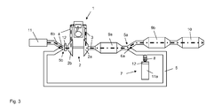
Figur 1 - Fig. 3
- schematisch die in
Figur 2 - Fig. 4
- schematisch die in
Figur 2 - Fig. 5
- schematisch die in
Figur 2 - Fig. 6
- schematisch eine zweite Ausführungsform der Brennkraftmaschine,
- Fig. 7
- schematisch die in
Figur 6 dargestellte Ausführungsform der Brennkraftmaschine in einem ersten Schaltungszustand, - Fig. 8
- schematisch die in
Figur 6 dargestellte Ausführungsform der Brennkraftmaschine in einem zweiten Schaltungszustand, - Fig. 9
- schematisch eine dritte Ausführungsform der Brennkraftmaschine, und
- Fig. 10
- schematisch eine vierte Ausführungsform der Brennkraftmaschine.
- Fig. 1
- schematically a first embodiment of the internal combustion engine,
- Fig. 2
- schematically the in
FIG. 1 illustrated internal combustion engine with sensors, - Fig. 3
- schematically the in
FIG. 2 illustrated embodiment of the internal combustion engine in a first circuit state, - Fig. 4
- schematically the in
FIG. 2 illustrated embodiment of the internal combustion engine in a second circuit state, - Fig. 5
- schematically the in
FIG. 2 illustrated embodiment of the internal combustion engine in a third circuit state, - Fig. 6
- schematically a second embodiment of the internal combustion engine,
- Fig. 7
- schematically the in
FIG. 6 illustrated embodiment of the internal combustion engine in a first circuit state, - Fig. 8
- schematically the in
FIG. 6 illustrated embodiment of the internal combustion engine in a second circuit state, - Fig. 9
- schematically a third embodiment of the internal combustion engine, and
- Fig. 10
- schematically a fourth embodiment of the internal combustion engine.
Die Brennkraftmaschine 1 verfügt über eine Ansaugleitung 4, über welche den Zylindern Frischluft bzw. Frischgemisch zugeführt wird und über eine Abgasleitung 3 zum Abführen der Verbrennungsgase aus den Zylindern. Die Ansaugleitung 4 ist mit einem Filter 11 ausgerüstet, um die angesaugte Luft zu reinigen.The
Zur Aufladung ist die Brennkraftmaschine 1 mit einem Abgasturbolader 2 ausgestattet, wobei die Turbine 2a in der Abgasleitung 3 und der dazugehörige Verdichter 2b des Abgasturboladers 2 in der Ansaugleitung 4 angeordnet ist. Auf diese Weise wird die Verbrennungsluft vor Eintritt in die Zylinder komprimiert, wozu die Abgasenthalpie der heißen Abgase in der Turbine 2a genutzt werden.For charging the
Stromabwärts der Turbine 2a sind zwei Abgasnachbehandlungssysteme 9a, 9b in der Abgasleitung 3 vorgesehen und am Ende der Abgasleitung 3 ist ein Schalldämpfer 10 angeordnet.Downstream of the
Zur Abgasrückführung ist eine erste Leitung 5 vorgesehen, die stromabwärts der Turbine 2a aus der Abgasleitung 3 unter Ausbildung einer ersten Abzweigung 5a abzweigt und stromaufwärts des Verdichters 2b in die Ansaugleitung 4 unter Ausbildung einer ersten Einmündung 5b einmündet. Folglich handelt es sich vorliegend um eine Niederdruck-AGR.For exhaust gas recirculation, a
Da die erste Abzweigung 5a stromabwärts des ersten Abgasnachbehandlungssystems 9a angeordnet ist, führt die Niederdruck-AGR ausschließlich bereits nachbehandeltes d. h. gereinigtes Abgas zurück.Since the
Zur Einstellung der Abgasmenge, welche über die erste Leitung 5 zurückgeführt wird, bzw. zur Aktivierung und Deaktivierung der Niederdruck-AGR ist ein Absperrelement 6a in Gestalt eine Klappe an der ersten Abzweigung 5a, an der die erste Leitung 5 zur Abgasrückführung von der Abgasleitung 3 abzweigt, angeordnet.To set the amount of exhaust gas, which is returned via the
An der ersten Einmündung 5b ist ebenfalls ein Absperrelement 6b in Gestalt einer Klappe vorgesehen, welches den Zustrom aus der ersten Rückführleitung 5 und der Ansaugleitung 4 regelt.At the
Die verschiedenen Schaltstellungen der Absperrelemente 6a, 6b bzw. Klappen werden im Zusammenhang mit den
An der ersten Leitung 5 zur Abgasrückführung ist eine Vorrichtung 7 zum Zuführen von Luft vorgesehen. Die Vorrichtung 7 saugt Luft über einen Filter 11a aus der Umgebung an, wobei ein Absperrelement 8 die Verbindung zu der ersten Leitung 5 freigibt, um Luft zur Verdünnung des Abgases in die Rückführleitung 5 einzuleiten, oder aber die Verbindung verschließt.On the
Ergänzend zu der in
Ein erster Luftmassensensor 12 ist stromaufwärts des Verdichters 2b und stromabwärts der ersten Einmündung 5b in der Ansaugleitung 4 vorgesehen und dient der meßtechnischen Erfassung des dem Verdichter 2b zugeführten Gasstroms, der Luft, Abgas und gegebenenfalls auch Kraftstoff enthalten kann.A first
Ein zweiter Luftmassensensor 12 ist Bestandteil der Vorrichtung 7 zum Zuführen von Luft und dient zur Bestimmung der in die erste Rückführleitung 5 eingeleiteten Luftmenge.A second
Das Absperrelement 6a an der ersten Abzweigung 5a verschließt die erste Rückführleitung 5, so dass die Niederdruck-AGR in dem Schaltungszustand gemäß
Das an der ersten Einmündung 5b vorgesehene Absperrelement 6b gibt folgerichtig nur die Ansaugleitung 4 frei und verschließt die erste Rückführleitung 5.The shut-off
Die angesaugte Luft tritt durch den Filter 11 in die Ansaugleitung 4 ein, passiert den Sensor 12, durchströmt den Verdichter 2b und wird in die Zylinder der Brennkraftmaschine 1 geleitet. Die aus den Zylindern in die Abgasleitung 3 abgeführten Abgase durchströmen die Turbine 2a, die Abgasnachbehandlungssysteme 9a, 9b und gelangen gereinigt in die Umgebung. Beide Gasströme, nämlich der Frischluftstrom und der Abgasstrom, sind als gestrichelte Linien dargestellt. Abgas wird vorliegend nicht zurückgeführt.The sucked air enters through the
Das Absperrelement 6a an der ersten Abzweigung 5a ist in einer Mittelstellung, in der es sowohl die Abgasleitung 3, die zum zweiten Abgasnachbehandlungssystem 9b führt, als auch die erste Rückführleitung 5 freigibt. Das an der ersten Einmündung 5b vorgesehene Absperrelement 6b gibt die erste Rückführleitung 5 frei und verschließt die Ansaugleitung 4.The shut-off
Gemäß dem Schaltungszustand der
Die Brennkraftmaschine 1 bzw. der Verdichter 2b saugt demnach verdünntes Abgas über die Rückführleitung 5 an und damit sowohl Abgas als auch Luft. Die Ansaugleitung 4 wird vorliegend zum Zuführen von Luft nicht benötigt und ist verschlossen. Die Gasströme, nämlich der Abgasstrom, der zur Verdünnung zugeführte Luftstrom und der mit Luft verdünnte rückgeführte Abgasstrom, sind als gestrichelte Linien dargestellt.The
Im Unterschied zu dem Schaltungszustand gemäß
Die Gasströme, nämlich der angesaugte Luftstrom, der Abgasstrom, der zur Verdünnung zugeführte Luftstrom und der mit Luft verdünnte rückgeführte Abgasstrom, sind als gestrichelte Linien dargestellt.The gas streams, namely the intake airflow, the exhaust gas flow, the airflow supplied for dilution, and the recirculated exhaust flow diluted with air are shown as dashed lines.
Ergänzend zu der in
In der Versorgungsleitung 15 sind stromaufwärts des Gasspeichers 13 eine Pumpe 14 und stromabwärts des Gasspeichers 13 ein Absperrelement 16 vorgesehen. Die Pumpe 14 dient der Förderung des Abgases in den Speicher 13. Mit dem Absperrelement 16 läßt sich der Gasspeicher 13 von der Ansaugleitung 4 trennen oder aber mit dieser verbinden.In the
Der Gasspeicher 13 verbessert das Ansprechverhalten der Niederdruck-AGR, weil unter Verwendung des Gasspeichers 13 auch im instationären Betrieb der Brennkraftmaschine 1 eine erhöhte Abgasmenge - durch direkte Entnahme aus dem Gasspeicher 13 - schnell bereitgestellt werden kann.The
Die Funktionsweise des Gasspeichers 13 wird im Zusammenhang mit den
Ausgehend von dem in
Das an der ersten Einmündung 5b vorgesehene Absperrelement 6b verschließt hingegen die erste Rückführleitung 5 und gibt lediglich die Ansaugleitung 4 frei. Gemäß dem Schaltungszustand dieses Absperrelements 6b ist die Niederdruck-AGR zwar deaktiviert und es wird kein Abgas in die Ansaugleitung 4 zurückgeführt. Die Rückführleitung 5 wird vorliegend aber zur Bevorratung des Gasspeichers 13 genutzt. Insofern wird auch mittels der Vorrichtung 7 Luft in die Rückführleitung 5 eingeleitet, um das dem Gasspeicher 13 zugeführte Abgas zu verdünnen. Das Absperrelement 16 ist geschlossen, so dass der Gasspeicher 13 von der Ansaugleitung 4 getrennt ist.By contrast, the shut-off
Die Gasströme, nämlich der via Ansaugleitung 4 angesaugte Luftstrom, der Abgasstrom, der zur Verdünnung zugeführte Luftstrom und der mit Luft verdünnte in den Gasspeicher 13 eingeleitete Abgasstrom, sind als gestrichelte Linien dargestellt.The gas flows, namely the air stream drawn in via
Im Unterschied zu dem in
Im Unterschied zu dem Schaltungszustand gemäß
Ergänzend zu der in
Hierzu ist eine zweite Leitung 17 zur Abgasrückführung vorgesehen, die stromaufwärts der Turbine 2a aus der Abgasleitung 3 unter Ausbildung einer zweiten Abzweigung 17a abzweigt und stromabwärts des Verdichters 2b in die Ansaugleitung 4 unter Ausbildung einer zweiten Einmündung 17b einmündet.For this purpose, a
Stromabwärts des Verdichters 2b und noch vor der zweiten Einmündung 17b ist ein Drosselelement 19 in der Ansaugleitung 4 vorgesehen, um das für die Förderung erforderliche Druckgefälle zwischen der Abgasleitung 3 und der Ansaugleitung 4 zu generieren.Downstream of the
Ein in der zweiten Rückführleitung 17 angeordnetes Absperrelement 18 dient der Einstellung der Rückführrate.An arranged in the
Bei der in
- 11
- aufgeladene Brennkraftmaschinecharged internal combustion engine
- 22
- Abgasturboladerturbocharger
- 2a2a
- Turbineturbine
- 2b2 B
- Verdichtercompressor
- 33
- Abgasleitungexhaust pipe
- 44
- Ansaugleitungsuction
- 55
- erste Leitung zur Abgasrückführungfirst line for exhaust gas recirculation
- 5a5a
- erste Abzweigungfirst turnoff
- 5b5b
- erste Einmündungfirst junction
- 6a6a
- Absperrelementshut-off
- 6b6b
- Absperrelementshut-off
- 77
- Vorrichtung zum Zuführen von LuftDevice for supplying air
- 88th
- Absperrelementshut-off
- 9a9a
- Abgasnachbehandlungssystemaftertreatment system
- 9b9b
- Abgasnachbehandlungssystemaftertreatment system
- 1010
- Schalldämpfersilencer
- 1111
- Filterfilter
- 11a11a
- Filterfilter
- 1212
- Sensorsensor
- 1313
- Gasspeichergas storage
- 1414
- Pumpepump
- 1515
- Versorgungsleitungsupply line
- 1616
- Absperrelementshut-off
- 1717
- zweite Leitung zur Abgasrückführungsecond line for exhaust gas recirculation
- 17a17a
- zweite Abzweigungsecond branch
- 17b17b
- zweite Einmündungsecond junction
- 1818
- Absperrelementshut-off
- 1919
- Drosselelementthrottle element
- AGRAGR
- AbgasrückführungExhaust gas recirculation
- mAGR m AGR
- Masse an zurückgeführtem AbgasMass of recirculated exhaust gas
- mFrischluft Fresh air
- Masse an zugeführter Frischluft bzw. VerbrennungsluftMass of supplied fresh air or combustion air
- xAGR x AGR
- AbgasrückführrateExhaust gas recirculation rate
Claims (11)
dadurch gekennzeichnet, dass
characterized in that
Priority Applications (2)
| Application Number | Priority Date | Filing Date | Title |
|---|---|---|---|
| EP08104882A EP2154355B1 (en) | 2008-07-25 | 2008-07-25 | Charged internal combustion engine with exhaust gas recirculation |
| CN2009201616566U CN201560837U (en) | 2008-07-25 | 2009-07-15 | Supercharged internal combustion engine with exhaust gas recirculation |
Applications Claiming Priority (1)
| Application Number | Priority Date | Filing Date | Title |
|---|---|---|---|
| EP08104882A EP2154355B1 (en) | 2008-07-25 | 2008-07-25 | Charged internal combustion engine with exhaust gas recirculation |
Publications (2)
| Publication Number | Publication Date |
|---|---|
| EP2154355A1 true EP2154355A1 (en) | 2010-02-17 |
| EP2154355B1 EP2154355B1 (en) | 2011-09-14 |
Family
ID=40010957
Family Applications (1)
| Application Number | Title | Priority Date | Filing Date |
|---|---|---|---|
| EP08104882A Expired - Fee Related EP2154355B1 (en) | 2008-07-25 | 2008-07-25 | Charged internal combustion engine with exhaust gas recirculation |
Country Status (2)
| Country | Link |
|---|---|
| EP (1) | EP2154355B1 (en) |
| CN (1) | CN201560837U (en) |
Cited By (6)
| Publication number | Priority date | Publication date | Assignee | Title |
|---|---|---|---|---|
| DE102010056238A1 (en) * | 2010-12-24 | 2012-06-28 | Audi Ag | Drive with an internal combustion engine and an expansion machine with gas recirculation |
| WO2015141754A1 (en) * | 2014-03-18 | 2015-09-24 | Toyota Jidosha Kabushiki Kaisha | Internal combustion engine |
| FR3041042A1 (en) * | 2015-09-14 | 2017-03-17 | Continental Automotive France | EXHAUST DEVICE OF AN INTERNAL COMBUSTION ENGINE COMPRISING AN ELECTRIC COMPRESSOR AND A COMPRESSED EXHAUST GAS TANK |
| DE102015220923A1 (en) * | 2015-10-27 | 2017-04-27 | Ford Global Technologies, Llc | Supercharged internal combustion engine with exhaust gas recirculation comprising a radiator |
| DE102011107250B4 (en) | 2010-07-23 | 2018-03-29 | GM Global Technology Operations LLC (n. d. Ges. d. Staates Delaware) | Exhaust gas recirculation system for an internal combustion engine and internal combustion engine with such an exhaust gas recirculation system |
| DE102020130684A1 (en) | 2020-11-20 | 2022-05-25 | Bayerische Motoren Werke Aktiengesellschaft | Exhaust system and method for exhaust gas recirculation in a motor vehicle and motor vehicle |
Families Citing this family (2)
| Publication number | Priority date | Publication date | Assignee | Title |
|---|---|---|---|---|
| KR101886095B1 (en) * | 2016-08-04 | 2018-08-07 | 현대자동차 주식회사 | Engine system having egr apparatus |
| CN114623024A (en) * | 2021-03-09 | 2022-06-14 | 长城汽车股份有限公司 | Engine, engine control method, and vehicle |
Citations (8)
| Publication number | Priority date | Publication date | Assignee | Title |
|---|---|---|---|---|
| DE9421145U1 (en) | 1994-04-28 | 1995-05-04 | Mtu Friedrichshafen Gmbh | Diesel internal combustion engine with a heat exchanger for exhaust gas cooling arranged in an exhaust gas recirculation line |
| WO1999015773A1 (en) * | 1997-09-22 | 1999-04-01 | Turbodyne Systems, Inc. | Fast acting exhaust gas recirculation system |
| JPH1193781A (en) * | 1997-09-19 | 1999-04-06 | Isuzu Motors Ltd | Egr device with egr cooler |
| DE10053675A1 (en) * | 2000-10-28 | 2002-05-08 | Volkswagen Ag | Controlled exhaust gas recycling system for vehicle engine includes air inlet- and exhaust recycle channels connected to partially-open three-way valve feeding inlet manifold |
| EP1308614A1 (en) * | 2001-10-31 | 2003-05-07 | Peugeot Citroen Automobiles SA | Drive system for motor vehicles |
| US20060021327A1 (en) * | 2004-07-30 | 2006-02-02 | Kiser Matthew T | Exhaust gas recirculation system having an electrostatic precipitator |
| WO2007062682A1 (en) * | 2005-11-29 | 2007-06-07 | Renault Trucks | Exhaust gas recirculation system and method for cleaning such a system |
| WO2007129160A1 (en) * | 2006-04-26 | 2007-11-15 | Toyota Jidosha Kabushiki Kaisha | Exhaust gas recirculation apparatus for internal combustion engine and method of controlling exhaust gas recirculation apparatus |
-
2008
- 2008-07-25 EP EP08104882A patent/EP2154355B1/en not_active Expired - Fee Related
-
2009
- 2009-07-15 CN CN2009201616566U patent/CN201560837U/en not_active Expired - Lifetime
Patent Citations (8)
| Publication number | Priority date | Publication date | Assignee | Title |
|---|---|---|---|---|
| DE9421145U1 (en) | 1994-04-28 | 1995-05-04 | Mtu Friedrichshafen Gmbh | Diesel internal combustion engine with a heat exchanger for exhaust gas cooling arranged in an exhaust gas recirculation line |
| JPH1193781A (en) * | 1997-09-19 | 1999-04-06 | Isuzu Motors Ltd | Egr device with egr cooler |
| WO1999015773A1 (en) * | 1997-09-22 | 1999-04-01 | Turbodyne Systems, Inc. | Fast acting exhaust gas recirculation system |
| DE10053675A1 (en) * | 2000-10-28 | 2002-05-08 | Volkswagen Ag | Controlled exhaust gas recycling system for vehicle engine includes air inlet- and exhaust recycle channels connected to partially-open three-way valve feeding inlet manifold |
| EP1308614A1 (en) * | 2001-10-31 | 2003-05-07 | Peugeot Citroen Automobiles SA | Drive system for motor vehicles |
| US20060021327A1 (en) * | 2004-07-30 | 2006-02-02 | Kiser Matthew T | Exhaust gas recirculation system having an electrostatic precipitator |
| WO2007062682A1 (en) * | 2005-11-29 | 2007-06-07 | Renault Trucks | Exhaust gas recirculation system and method for cleaning such a system |
| WO2007129160A1 (en) * | 2006-04-26 | 2007-11-15 | Toyota Jidosha Kabushiki Kaisha | Exhaust gas recirculation apparatus for internal combustion engine and method of controlling exhaust gas recirculation apparatus |
Cited By (7)
| Publication number | Priority date | Publication date | Assignee | Title |
|---|---|---|---|---|
| DE102011107250B4 (en) | 2010-07-23 | 2018-03-29 | GM Global Technology Operations LLC (n. d. Ges. d. Staates Delaware) | Exhaust gas recirculation system for an internal combustion engine and internal combustion engine with such an exhaust gas recirculation system |
| DE102010056238A1 (en) * | 2010-12-24 | 2012-06-28 | Audi Ag | Drive with an internal combustion engine and an expansion machine with gas recirculation |
| US9096116B2 (en) | 2010-12-24 | 2015-08-04 | Audi Ag | Drive with an internal combustion engine and an expansion machine with gas return |
| WO2015141754A1 (en) * | 2014-03-18 | 2015-09-24 | Toyota Jidosha Kabushiki Kaisha | Internal combustion engine |
| FR3041042A1 (en) * | 2015-09-14 | 2017-03-17 | Continental Automotive France | EXHAUST DEVICE OF AN INTERNAL COMBUSTION ENGINE COMPRISING AN ELECTRIC COMPRESSOR AND A COMPRESSED EXHAUST GAS TANK |
| DE102015220923A1 (en) * | 2015-10-27 | 2017-04-27 | Ford Global Technologies, Llc | Supercharged internal combustion engine with exhaust gas recirculation comprising a radiator |
| DE102020130684A1 (en) | 2020-11-20 | 2022-05-25 | Bayerische Motoren Werke Aktiengesellschaft | Exhaust system and method for exhaust gas recirculation in a motor vehicle and motor vehicle |
Also Published As
| Publication number | Publication date |
|---|---|
| CN201560837U (en) | 2010-08-25 |
| EP2154355B1 (en) | 2011-09-14 |
Similar Documents
| Publication | Publication Date | Title |
|---|---|---|
| EP2154355B1 (en) | Charged internal combustion engine with exhaust gas recirculation | |
| DE10112521B4 (en) | diesel engine | |
| DE102014201709B4 (en) | Exhaust-engine-loaded internal combustion engine with exhaust aftertreatment and method for operating such an internal combustion engine | |
| DE19914787C2 (en) | Emission control system for an internal combustion engine | |
| DE102014201579A1 (en) | Internal combustion engine with selective catalyst for reducing nitrogen oxides and method for operating such an internal combustion engine | |
| EP2635777B1 (en) | Motor vehicle internal combustion engine and method for operating a motor vehicle internal combustion engine | |
| EP1640597A1 (en) | Supercharged internal combustion engine and method for operating such an internal combustion engine | |
| EP2183471A1 (en) | Exhaust-gas secondary treatment preceding a turbocharger | |
| DE102008043487A1 (en) | Internal combustion engine with turbocharger and oxidation catalyst | |
| DE102016212249B4 (en) | Two-stage turbocharged direct-injection internal combustion engine with exhaust aftertreatment and method for operating such an internal combustion engine | |
| DE102010060330A1 (en) | Method for monitoring a pollutant concentration in the exhaust gas of an internal combustion engine | |
| DE112007002869T5 (en) | Low pressure EGR system with full range capability | |
| DE102010003337A1 (en) | Motor car, has gas recirculation circuit guided from exhaust gas tract to intake tract of engine via radiator and exhaust gas recirculation valve, and another gas recirculation circuit directly guided from exhaust gas tract to intake tract | |
| DE102017111454A1 (en) | Otto engine with particle filter and method for operating a gasoline engine | |
| DE102015217394B4 (en) | Method for controlling a particle filter and motor vehicle | |
| DE102009020625A1 (en) | Internal combustion engine i.e. diesel engine, for motor vehicle, has oxidation catalyzer arranged upstream to turbine of turbocharger in surges provided for recycling exhaust gas, and switching device provided upstream to catalyzer | |
| DE102013008827A1 (en) | Charged internal combustion engine | |
| DE102019005155A1 (en) | Internal combustion engine for a motor vehicle, in particular for a motor vehicle, and a method for operating such an internal combustion engine | |
| EP2058485A1 (en) | Charged combustion engine and method for operating such a combustion engine | |
| DE102009051027B4 (en) | Drive unit with a diesel internal combustion engine and exhaust gas recirculation as well as a method for operating such a drive unit | |
| DE102013202299A1 (en) | Internal combustion engine e.g. petrol engine for use in motor vehicle, has dosing device provided for introducing liquid urea into bypass line as reducing agent for selective catalyst arranged in exhaust gas removal system | |
| DE102018120179B4 (en) | Exhaust tract for an internal combustion engine and internal combustion engine | |
| DE102015220039A1 (en) | Operating method and motor vehicle | |
| DE102008013254B4 (en) | Method for operating an internal combustion engine with exhaust gas recirculation | |
| EP2058486B1 (en) | Charged combustion engine and method for operating such a combustion engine |
Legal Events
| Date | Code | Title | Description |
|---|---|---|---|
| PUAI | Public reference made under article 153(3) epc to a published international application that has entered the european phase |
Free format text: ORIGINAL CODE: 0009012 |
|
| AK | Designated contracting states |
Kind code of ref document: A1 Designated state(s): AT BE BG CH CY CZ DE DK EE ES FI FR GB GR HR HU IE IS IT LI LT LU LV MC MT NL NO PL PT RO SE SI SK TR |
|
| AX | Request for extension of the european patent |
Extension state: AL BA MK RS |
|
| 17P | Request for examination filed |
Effective date: 20100817 |
|
| AKX | Designation fees paid |
Designated state(s): DE FR GB |
|
| RTI1 | Title (correction) |
Free format text: CHARGED INTERNAL COMBUSTION ENGINE WITH EXHAUST GAS RECIRCULATION |
|
| GRAP | Despatch of communication of intention to grant a patent |
Free format text: ORIGINAL CODE: EPIDOSNIGR1 |
|
| GRAS | Grant fee paid |
Free format text: ORIGINAL CODE: EPIDOSNIGR3 |
|
| GRAA | (expected) grant |
Free format text: ORIGINAL CODE: 0009210 |
|
| AK | Designated contracting states |
Kind code of ref document: B1 Designated state(s): DE FR GB |
|
| REG | Reference to a national code |
Ref country code: GB Ref legal event code: FG4D Free format text: NOT ENGLISH |
|
| REG | Reference to a national code |
Ref country code: DE Ref legal event code: R096 Ref document number: 502008004853 Country of ref document: DE Effective date: 20111110 |
|
| PLBE | No opposition filed within time limit |
Free format text: ORIGINAL CODE: 0009261 |
|
| STAA | Information on the status of an ep patent application or granted ep patent |
Free format text: STATUS: NO OPPOSITION FILED WITHIN TIME LIMIT |
|
| 26N | No opposition filed |
Effective date: 20120615 |
|
| REG | Reference to a national code |
Ref country code: DE Ref legal event code: R097 Ref document number: 502008004853 Country of ref document: DE Effective date: 20120615 |
|
| REG | Reference to a national code |
Ref country code: FR Ref legal event code: PLFP Year of fee payment: 9 |
|
| REG | Reference to a national code |
Ref country code: FR Ref legal event code: PLFP Year of fee payment: 10 |
|
| REG | Reference to a national code |
Ref country code: FR Ref legal event code: PLFP Year of fee payment: 11 |
|
| PGFP | Annual fee paid to national office [announced via postgrant information from national office to epo] |
Ref country code: FR Payment date: 20190621 Year of fee payment: 12 |
|
| PGFP | Annual fee paid to national office [announced via postgrant information from national office to epo] |
Ref country code: GB Payment date: 20190626 Year of fee payment: 12 |
|
| GBPC | Gb: european patent ceased through non-payment of renewal fee |
Effective date: 20200725 |
|
| PG25 | Lapsed in a contracting state [announced via postgrant information from national office to epo] |
Ref country code: FR Free format text: LAPSE BECAUSE OF NON-PAYMENT OF DUE FEES Effective date: 20200731 Ref country code: GB Free format text: LAPSE BECAUSE OF NON-PAYMENT OF DUE FEES Effective date: 20200725 |
|
| PGFP | Annual fee paid to national office [announced via postgrant information from national office to epo] |
Ref country code: DE Payment date: 20220615 Year of fee payment: 15 |
|
| P01 | Opt-out of the competence of the unified patent court (upc) registered |
Effective date: 20230620 |
|
| REG | Reference to a national code |
Ref country code: DE Ref legal event code: R119 Ref document number: 502008004853 Country of ref document: DE |
|
| PG25 | Lapsed in a contracting state [announced via postgrant information from national office to epo] |
Ref country code: DE Free format text: LAPSE BECAUSE OF NON-PAYMENT OF DUE FEES Effective date: 20240201 |