EP2153262B1 - Durchlichtmikroskop - Google Patents
Durchlichtmikroskop Download PDFInfo
- Publication number
- EP2153262B1 EP2153262B1 EP08785162A EP08785162A EP2153262B1 EP 2153262 B1 EP2153262 B1 EP 2153262B1 EP 08785162 A EP08785162 A EP 08785162A EP 08785162 A EP08785162 A EP 08785162A EP 2153262 B1 EP2153262 B1 EP 2153262B1
- Authority
- EP
- European Patent Office
- Prior art keywords
- changer
- optical elements
- stand base
- transmitted light
- light microscope
- Prior art date
- Legal status (The legal status is an assumption and is not a legal conclusion. Google has not performed a legal analysis and makes no representation as to the accuracy of the status listed.)
- Active
Links
Images

Classifications
-
- G—PHYSICS
- G02—OPTICS
- G02B—OPTICAL ELEMENTS, SYSTEMS OR APPARATUS
- G02B21/00—Microscopes
- G02B21/24—Base structure
- G02B21/248—Base structure objective (or ocular) turrets
-
- G—PHYSICS
- G02—OPTICS
- G02B—OPTICAL ELEMENTS, SYSTEMS OR APPARATUS
- G02B21/00—Microscopes
- G02B21/06—Means for illuminating specimens
- G02B21/08—Condensers
- G02B21/086—Condensers for transillumination only
Definitions
- the present invention relates to a transmitted light microscope according to the preamble of claim 1 with a stand base, an object table arranged above the stand, an observation optics arranged above the object table, an illumination module arranged at least partially within the stand base, which has a deflecting element inside the stand base and its illumination beam path in Stativfuß extends horizontally to the deflecting element and is deflected by this vertically upwards to the stage, and with a rotatable around a rotation axis and a plurality of optical elements supporting changer in the stand base, wherein by rotation of the changer about the axis of rotation selectively the individual optical elements in the illumination beam path within the Tripod foot can be introduced.
- the changers of such transmitted-light microscopes are often disk-shaped, which carry in the circumferential direction of the disk a plurality of optical elements (for example filters) whose optical axes are parallel to the axis of rotation of the disk.
- the changer are arranged in the stand so that the axis of rotation is horizontal, so that the disc-shaped changer stands upright in the stand and therefore requires a relatively large amount of space in the vertical direction.
- the JP 2002-031763 is a substantially disc-shaped changer known, which is detachably attachable to the transmitted light microscope.
- the essentially disc-shaped changer is arranged between the stand base and the object table. Since the changer is arranged outside of the stand base, its dimensions in the horizontal direction can be significantly greater than that of the stand base.
- a transmitted light microscope having the features of the preamble of claim 1 is known from EP 1 772 764 A2 known.
- the JP 2006-189616 A shows a reflected light microscope, in which a rotatable changer is provided in the illumination beam path, with which selectively one of a plurality of optical elements can be introduced in the illumination beam path.
- the object is achieved in a transmitted light microscope of the type mentioned above in that the changer is arranged so that the deflection element is surrounded by the optical elements, and that the introduced by means of the changer in the illumination beam path optical element in the horizontal portion of the illumination beam path is arranged.
- optical elements can completely or partially surround the deflection element.
- the extent of the changer in the horizontal direction is greater than in the vertical direction. This allows the existing space in the stand base to be used optimally, since the stand base is usually wider than it is tall.
- the changer can wear each optical element so that the optical axis of the optical element is horizontal, whereby the optical elements are upright.
- the optical axis of each optical element may be substantially perpendicular to the axis of rotation of the changer. This can be done e.g. to make sure that unwanted reflections do not adversely affect the imaging properties of the transmitted light microscope.
- the undesired reflections e.g. out of the illumination beam path.
- the deviation from the vertical arrangement is only a few degrees, e.g. between 0-10 ° or between 0 - 5 °.
- the upright arrangement of the optical elements, the extent of the changer can be reduced in the horizontal direction, since the thickness of the optical elements is usually much smaller than their diameter or their extension in the upright direction.
- the optical elements may be arranged annularly (e.g., annularly) about the axis of rotation. This is a particularly advantageous arrangement to provide a compact changer.
- the optical elements are arranged only on a portion of an imaginary ring which surrounds the axis of rotation, and thus on a ring segment. In this case, the optical elements partially enclose the axis of rotation.
- the optical elements can be arranged uniformly along the circumference of the changer.
- the changer can carry an odd number of optical elements.
- a second changer in addition to the changer, which is referred to below as the first changer, a second changer can be arranged in the stand base.
- the second changer preferably has the basically same structure as the first changer.
- the second changer can be rotatable about a vertically extending second axis of rotation and carry a plurality of second optical elements which surround the optical elements of the first changer. It is thus possible a concentric arrangement of the optical elements by means of the two changer. Thus, the optical effects of the optical elements of the two changer can be combined. Also, this concentric arrangement is extremely space-saving to significantly increase the number of optical elements that can be introduced into the illumination beam path.
- the axis of rotation of the second changer may coincide with the axis of rotation of the first changer.
- the changer (s) can be manually operated. However, it is also possible to provide one or more corresponding motors in order to turn the changer or motor driven.
- the changer (s) may each have a rotational position in which none of the optical elements carried by the changer is introduced in the illumination beam path. In this rotational position, an effect-neutral passage of the light of the illumination module can be ensured by the changer.
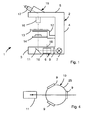
- the transmitted-light microscope 1 comprises a microscope housing 2 with a stand base 3, a vertical one Housing portion 4 and a horizontal housing portion 5, so that the microscope housing 2 is formed in side view substantially C-shaped.
- a lighting module 6 which comprises a schematically illustrated light source 7, an illumination optical system 8, a changer 10 bearing a plurality of optical elements 9 described in more detail below and a deflecting element 11.
- the illumination beam path extends within the tripod base 3 of the light source 7 to the deflecting element 11 in the horizontal direction and is then deflected by the deflecting element by 90 ° in the vertical direction upwards.
- a displaceable in the vertical direction support 12 On the vertical housing portion 4 a displaceable in the vertical direction support 12 is arranged, on the one hand carries a stage 13 and on the other hand, a condenser 14. By means of the carrier 12, the object table 13 and the condenser optics 14 can be displaced in the vertical direction.
- the carrier 12 typically has means for adjusting the distance between the stage 13 and the condenser optics 14.
- the viewing optics 15 may include a plurality of lenses 16 mounted on a rotatable nosepiece (not shown).
- the changer 10 has a base plate 25 with six holders 26, three of which support neutral gray filters as optical elements 9.
- the filters 9 are, in the plan view of Fig. 3 seen, arranged on a circular ring and circumferentially spaced by 60 ° from each other.
- the changer 10 is rotatably mounted, wherein its axis of rotation 18 extends vertically and thus perpendicular to the horizontally extending portion of the illumination beam path in the stand 3.
- the filters 9 are supported in the changer 10 so that they are arranged vertically or stand upright. Thus, their optical axes each extend horizontally and thus perpendicular to the axis of rotation 18.
- the changer 10 is arranged in the stand base 3 that a portion of the corrugated edge 27 of the base plate 25 by a lateral opening (not shown) from the stand base 3 protrudes outwardly so that a user of the microscope 1, the base plate 25 rotate about the axis of rotation 18 and thus can bring the desired filter 9 in the illumination beam path in the tripod base 3.
- the changer 10 may be formed so that in a rotational position, none of the filters 9 in the illumination beam path.
- the stand base is usually wider than high, 10 more optical elements in the illumination beam path can be provided by means of the changer compared to the case in which arranged a Farbfilterrad in a known manner with horizontally extending axis of rotation in the horizontally extending portion of the illumination beam path in the stand base is.
- the optical elements 9 may be circumferentially spaced apart by 120 °, so that in the beam path always at most exactly one optical element 9 is arranged.
- the illumination beam path passes through one of the optical elements 9 and then through the gap between the two other optical elements 9 therethrough.
- the changer may comprise an odd number of optical elements, which are arranged uniformly on the circumference of the changer, so that between each two optical elements an equally large space for the passage of the illumination radiation is present.
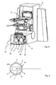
- FIGS. 5 and 6 is a first embodiment of the transmitted light microscope 1 according to the invention, which is a modification of the transmitted light microscope according to Fig. 1 to 3 is shown, wherein like elements are designated by like reference numerals and reference is made to the description thereof to the above embodiments.
- the changer 10 is arranged so that the optical elements 9 surround the deflecting element 11.
- the illumination beam path in the plan view of Fig. 6 seen, only about half the changer 10, which leads to the advantage that the optical elements 9 can lie opposite each other on the annulus.
- the changer in the embodiment of FIGS. 5 and 6 carry six different optical elements 9 and thus twice as many as the changer 10 of the examples of Fig. 1 to 4 ,
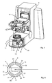
- FIGS. 7 and 8 is a development of the embodiment of FIGS. 5 and 6 shown, so that essentially only the differences will be described.
- a second changer 20 is provided, which basically has the same structure as the first changer 10 and in turn six optical elements 21 upright standing wearing, wherein the optical elements 21, in the plan view of Fig. 8 seen, are arranged in a slightly larger circular ring than the optical elements 9 of the first changer 10.
- the axis of rotation of the further changer 20 extends vertically and preferably coincides with the axis of rotation 18 of the changer 10.
- the optical elements 9 and 21 may be filters.
- the filters can be designed as neutral gray filters in order to be able to perform color-neutral attenuation of the light of the light source 7, color filters, polarizers, attenuation filters, etc.
- the optical elements 9, 21 are optical elements for beam shaping, e.g. refractive and / or diffractive elements.
- the described changer 10, 20 can each be rotated manually.
- a drive e.g., electric motor
Landscapes
- Physics & Mathematics (AREA)
- Chemical & Material Sciences (AREA)
- Analytical Chemistry (AREA)
- General Physics & Mathematics (AREA)
- Optics & Photonics (AREA)
- Microscoopes, Condenser (AREA)
- Optical Filters (AREA)
Description
- Die vorliegende Erfindung betrifft ein Durchlichtmikroskop gemäß dem Oberbegriff des Anspruches 1 mit einem Stativfuß, einem oberhalb des Stativfußes angeordneten Objekttisch, einer oberhalb des Objekttisches angeordneten Beobachtungsoptik, einem zumindest teilweise innerhalb des Stativfußes angeordneten Beleuchtuhgsmodul, das innerhalb des Stativfußes ein Umlenkelement aufweist und dessen Beleuchtungsstrahlengang im Stativfuß horizontal bis zum Umlenkelement verläuft und von diesem vertikal nach oben zum Objekttisch hin umgelenkt wird, und mit einem um eine Drehachse drehbaren und mehrere Optikelemente tragenden Wechsler im Stativfuß, wobei durch Drehung des Wechslers um die Drehachse selektiv die einzelnen Optikelemente in den Beleuchtungsstrahlengang innerhalb des Stativfußes eingebracht werden können.
- Die Wechsler solcher Durchlichtmikroskope sind häufig scheibenförmig ausgebildet, die in Umfangsrichtung der Scheibe mehrere Optikelemente (z.B. Filter) tragen, deren optische Achsen parallel zur Drehachse der Scheibe verlaufen. Die Wechsler sind im Stativfuß so angeordnet, daß die Drehachse horizontal verläuft, so daß der scheibenförmige Wechsler im Stativfuß aufrecht steht und daher relativ viel Platz in vertikaler Richtung benötigt.
- Aus der
JP 2002-031763 - Ein Durchlichtmikroskop mit dem Merkmalen des Oberbegriffs des Anspruches 1 ist aus der
EP 1 772 764 A2 bekannt. - Die
JP 2006-189616 A - Ausgehend hiervon ist es Aufgabe der Erfindung, ein Durchlichtmikroskop der eingangs genannten Art derart weiterzubilden, daß der Wechsler mit den mehreren Optikelementen im Stativfuß so vorgesehen werden kann, daß eine möglichst große Anzahl von Optikelemente bei einem möglichst geringen Platzbedarf im Stativfuß bereitgestellt werden kann.
- Erfindungsgemäß wird die Aufgabe bei einem Durchlichtmikroskop der eingangs genannten Art dadurch gelöst, daß der Wechsler so angeordnet ist, daß das Umlenkelement von den Optikelementen umgeben ist, und daß das mittels dem Wechsler in den Beleuchtungsstrahlengang eingebrachte Optikelement im horizontalen Abschnitt des Beleuchtungsstrahlenganges angeordnet ist.
- Dies ist eine besonders kompakte und platzsparende Anordnung des Wechslers. Insbesondere können die Optikelemente das Umlenkelement vollständig oder teilweise umgeben.
- Aufgrund der vertikalen Ausrichtung der Drehachse des Wechslers ist die Ausdehnung des Wechslers in horizontaler Richtung größer als in vertikaler Richtung. Dadurch kann der vorhandene Platz im Stativfuß optimal genutzt werden, da der Stativfuß in der Regel breiter als hoch ist.
- Insbesondere kann der Wechsler jedes Optikelement so tragen, daß die optische Achse des Optikelements horizontal verläuft, wodurch die Optikelemente aufrecht stehen. Anders gesagt, die optische Achse jedes Optikelementes kann im wesentlichen senkrecht zur Drehachse des Wechslers verlaufen. Dies kann man z.B. dazu nutzen, daß unerwünschte Reflexe nicht nachteilig die Abbildungseigenschaften des Durchlichtmikroskops verschlechtern. Durch ein leichtes Schrägstellen (also nicht exakt senkrecht) der Optikelemente laufen die unerwünschten Reflexe z.B. aus dem Beleuchtungsstrahlengang heraus. Bevorzugt beträgt die Abweichung von der senkrechten Anordnung nur einige Grad, z.B. zwischen 0-10° oder zwischen 0 - 5°. Durch die aufrechte Anordnung der Optikelemente kann die Ausdehnung des Wechslers in horizontaler Richtung verringert werden, da die Dicke der optischen Elemente in der Regel sehr viel geringer ist als ihr Durchmesser bzw. ihre Ausdehnung in aufrechter Richtung.
- Insbesondere können die Optikelemente ringförmig (z.B. kreisringförmig) um die Drehachse angeordnet sein. Dies ist eine besonders vorteilhafte Anordnung, um einen kompakten Wechsler bereitzustellen.
- Ferner ist es möglich, daß die Optikelemente nur auf einem Abschnitt eines gedachten Ringes, der die Drehachse umgibt, und somit auf einem Ringsegment angeordnet sind. In diesem Fall umschließen die Optikelemente die Drehachse teilweise.
- Die Optikelemente können entlang des Umfangs des Wechslers gleichmäßig angeordnet werden.
- Insbesondere kann der Wechsler eine ungerade Anzahl von Optikelementen tragen.
- Bei dem erfindungsgemäßen Durchlichtmikroskop kann zusätzlich zu dem Wechsler, der nachfolgend als erster Wechsler bezeichnet wird, ein zweiter Wechsler im Stativfuß angeordnet sein. Der zweite Wechsler weist bevorzugt den grundsätzlich gleichen Aufbau wie der erste Wechsler auf.
- So kann der zweite Wechsler um eine vertikal verlaufende zweite Drehachse drehbar sein und mehrere zweite Optikelemente tragen, die die Optikelementen des ersten Wechsler umgeben. Es ist somit eine konzentrische Anordnung der Optikelemente mittels der beiden Wechsler möglich. Damit können die optischen Wirkungen der Optikelemente der beiden Wechsler miteinander kombiniert werden. Auch ist diese konzentrische Anordnung außerordentlich platzsparend, um die Anzahl der Optikelemente, die in den Beleuchtungsstrahlengang eingebracht werden können, deutlich zu erhöhen.
- Insbesondere kann die Drehachse des zweiten Wechslers mit der Drehachse des ersten Wechslers zusammenfallen.
- Der bzw. die Wechsler können manuell betätigt werden. Es ist jedoch auch möglich, einen bzw. mehrere entsprechende Motoren vorzusehen, um den bzw. die Wechsler motorbetrieben drehen zu können.
- Der bzw. die Wechsler können jeweils eine Drehstellung aufweisen, in der keines der durch den Wechsler getragenen Optikelemente im Beleuchtungsstrahlengang eingebracht ist. In dieser Drehstellung kann ein wirkneutraler Durchgang des Lichtes des Beleuchtungsmoduls durch den Wechsler gewährleistet werden.
- Es versteht sich, daß die vorstehend genannten und die nachstehend noch zu erläuternden Merkmale nicht nur in den angegebenen Kombinationen, sondern auch in anderen Kombinationen oder in Alleinstellung einsetzbar sind, ohne den Rahmen der vorliegenden Erfindung zu verlassen.
- Nachfolgend wird die Erfindung beispielsweise anhand der beigefügten Zeichnungen, die auch erfindungswesentliche Merkmale offenbaren, noch näher erläutert, wobei in Verbindung mit
Figuren 1 bis 4 zwei Durchlichtmikroskope beschrieben werden, die zwar keine erfindungsgemäße Durchlichtmikroskope sind, aber deren Beschreibung zum besseren Verständnis der nachfolgend in Verbindung mitFiguren 5 bis 8 beschriebenen Ausführungsformen des erfindungsgemäßen Durchlichtmikroskops dient. Es zeigen: - Fig. 1
- eines schematische Ansicht eines Durchlichtmikroskops;
- Fig. 2
- eine perspektivische Teilansicht des unteren Teils des Durchlichtmikroskops von
Fig. 1 ; - Fig. 3
- eine schematische Draufsicht zur Erläuterung der Anordnung der Optikelemente 9 des Wechslers 10 von
Fig. 2 ; - Fig. 4
- eine schematische Draufsicht einer Abwandlung der Anordnung der Optikelemente 9 des Wechslers 10;
- Fig. 5
- eine perspektivische Teilansicht einer ersten Ausführungsform des erfindungsgemäßen Durchlichtmikroskopes;
- Fig. 6
- eine schematische Draufsicht zur Erläuterung der Anordnung der Optikelemente 9 des Wechslers 10 von
Fig. 5 ; - Fig. 7
- eine perspektivische Teilansicht einer zweiten Ausführungsform des erfindungsgemäßen Durchlichtmikroskops; und
- Fig. 8
- eine schematische Draufsicht zur Erläuterung der Anordnung der Optikelemente 9 und 21 der Wechsler 10, 20 von
Fig. 7 . - Bei den in
Fig. 1 bis 3 dargestellten Ausführungsform umfaßt das Durchlichtmikroskop 1 ein Mikroskopgehäuse 2 mit einem Stativfuß 3, einem senkrechten Gehäuseabschnitt 4 sowie einen waagrechten Gehäuseabschnitt 5, so daß das Mikroskopgehäuse 2 in Seitenansicht im wesentlichen C-förmig ausgebildet ist. - Innerhalb des Stativfußes 3 und des unteren Teils des senkrechten Gehäuseabschnitts 4 ist ein Beleuchtungsmodul 6 angeordnet, das eine schematisch dargestellte Lichtquelle 7, eine Beleuchtungsoptik 8, einen nachfolgend im Detail noch näher beschriebenen, mehrere Optikelemente 9 tragenden Wechsler 10 sowie ein Umlenkelement 11 umfaßt.
- Wie durch die in
Fig. 1 dargestellte Strichlinie ersichtlich ist, verläuft der Beleuchtungsstrahlengang innerhalb des Stativfußes 3 von der Lichtquelle 7 bis zum Umlenkelement 11 in horizontaler Richtung und wird dann vom Umlenkelement um 90° in vertikaler Richtung nach oben umgelenkt. - Am senkrechten Gehäuseabschnitt 4 ist ein in vertikaler Richtung verschiebbarer Träger 12 angeordnet, der einerseits einen Objekttisch 13 und andererseits eine Kondensoroptik 14 trägt. Mittels dem Träger 12 kann der Objekttisch 13 und die Kondensoroptik 14 in vertikaler Richtung verschoben werden. Der Träger 12 weist typischerweise Mittel zum Verstellen des Abstandes zwischen Objekttisch 13 und Kondensoroptik 14 auf.
- An dem waagrechten Gehäuseabschnitt 5 ist eine übliche Mikroskopbeobachtungsoptik 15 mit einem Objektiv 16 und einer Tubusoptik 17 angeordnet. Natürlich kann die Beobachtungsoptik 15 mehrere Objektive 16 aufweisen, die an einem drehbaren Objektivrevolver (nicht gezeigt) befestigt sind.
- Bei der in
Fig. 1 bis 3 gezeigten Ausführungsform weist der Wechsler 10 eine Grundplatte 25 mit sechs Haltern 26 auf, von denen drei als Optikelemente 9 Neutralgraufilter haltern. Die Filter 9 sind, in der Draufsicht vonFig. 3 gesehen, auf einem Kreisring angeordnet und in Umfangsrichtung um jeweils 60° voneinander beabstandet. - Der Wechsler 10 ist drehbar gelagert, wobei seine Drehachse 18 vertikal verläuft und somit senkrecht zum horizontal verlaufenden Abschnitt des Beleuchtungsstrahlengangs im Stativfuß 3. Die Filter 9 sind im Wechsler 10 so gehaltert, daß sie vertikal angeordnet sind bzw. aufrecht stehen. Somit erstrecken sich ihre optischen Achsen jeweils horizontal und damit senkrecht zur Drehachse 18. Der Wechsler 10 ist so im Stativfuß 3 angeordnet, daß ein Abschnitt des geriffelten Randes 27 der Grundplatte 25 durch eine seitliche Öffnung (nicht gezeigt) aus dem Stativfuß 3 nach außen vorsteht, so daß ein Benutzer des Mikroskops 1 die Grundplatte 25 um die Drehachse 18 drehen und damit den gewünschten Filter 9 in den Beleuchtungsstrahlengang im Stativfuß 3 einbringen kann. Durch die Umfangsrichtung um 60° versetzte Anordnung der Filter 9 ist sichergestellt, daß immer nur genau ein einziger Filter 9 im Beleuchtungsstrahlengang angeordnet ist. Natürlich kann der Wechsler 10 so ausgebildet sein, daß in einer Drehstellung keiner der Filter 9 im Beleuchtungsstrahlengang ist.
- Da bei Mikroskopen der Stativfuß in der Regel breiter als hoch ist, können mittels dem Wechsler 10 mehr Optikelemente im Beleuchtungsstrahlengang vorgesehen werden im Vergleich zu dem Fall, bei dem ein Farbfilterrad in bekannter Weise mit waagrecht verlaufender Drehachse im horizontal verlaufenden Abschnitt des Beleuchtungsstrahlengangs im Stativfuß angeordnet ist.
- Wie der Darstellung von
Fig. 4 zu entnehmen ist, in der eine Abwandlung der Anordnung der Filter 9 auf der Grundplatte 25 gezeigt ist, können die Optikelemente 9 in Umfangsrichtung um 120° voneinander beabstandet angeordnet sein, so daß im Strahlengang immer höchstens genau ein Optikelement 9 angeordnet ist. Bei dem inFig. 4 gezeigten Beispiel verläuft der Beleuchtungsstrahlengang durch eines der Optikelemente 9 und dann durch die Lücke zwischen den beiden anderen Optikelementen 9 hindurch. - Insbesondere kann der Wechsler eine ungerade Anzahl von Optikelementen umfassen, die gleichmäßig auf dem Umfang des Wechslers angeordnet sind, so daß zwischen jeweils zwei Optikelementen ein gleich großer Zwischenraum zum Durchlaß der Beleuchtungsstrahlung vorhanden ist.
- In
Fig. 5 und 6 ist eine erste Ausführungsform des erfindungsgemäßen Durchlichtmikroskops 1, die eine Abwandlung des Durchlichtmikroskops gemäßFig. 1 bis 3 ist dargestellt, wobei gleiche Elemente mit gleichen Bezugszeichen bezeichnet sind und zu deren Beschreibung auf die obigen Ausführungen verwiesen wird. - Bei der Ausführungsform von
Fig. 5 und 6 ist der Wechsler 10 so angeordnet, daß die Optikelemente 9 das Umlenkelement 11 umschließen. Dadurch verläuft der Beleuchtungsstrahlengang, in der Draufsicht vonFig. 6 gesehen, nur noch etwa durch den halben Wechsler 10, was zu dem Vorteil führt, daß die Optikelemente 9 auf dem Kreisring einander gegenüber liegen können. Somit kann der Wechsler bei der Ausführungsform vonFig. 5 und 6 sechs verschiedene Optikelemente 9 tragen und somit doppelt so viele wie die Wechsler 10 der Beispiele vonFig. 1 bis 4 . - In den
Fig. 7 und 8 ist eine Weiterbildung der Ausführungsform vonFig. 5 und 6 gezeigt, so daß im wesentlichen nur die Unterschiede beschrieben werden. Zusätzlich zu dem ersten Wechsler 10 ist ein zweiter Wechsler 20 vorgesehen, der grundsätzlich den gleichen Aufbau wie der erste Wechsler 10 aufweist und der wiederum sechs Optikelemente 21 aufrecht stehend trägt, wobei die Optikelemente 21, in der Draufsicht vonFig. 8 gesehen, in einem etwas größeren Kreisring als die Optikelemente 9 des ersten Wechslers 10 angeordnet sind. Die Drehachse des weiteren Wechslers 20 verläuft vertikal und fällt bevorzugt mit der Drehachse 18 des Wechslers 10 zusammen. Durch diese konzentrische Anordnung der Optikelemente 9 und 21 können bei der Ausführungsform vonFig. 7 und 8 nun doppelt so viele Optikelemente vorgesehen werden im Vergleich zu der Ausführungsform vonFig. 5 und 6 , ohne daß der dazu notwendige Platzbedarf deutlich ansteigt. - Natürlich ist es bei den Ausführungsformen von
Fig. 5 bis 8 möglich, daß die Wechsler 10 und 20 jeweils nur fünf Optikelemente 9, 21 tragen, so daß jeder Wechsler 10, 20 eine Drehstellung aufweist, bei der kein Optikelement 9, 21 im Beobachtungsstrahlengang angeordnet ist. - Bei den Optikelementen 9 und 21 kann es sich, wie bereits beschrieben, um Filter handeln. Insbesondere können die Filter als Neutralgraufilter, um eine farbneutrale Abschwächung des Lichtes der Lichtquelle 7 durchführen zu können, Farbfilter, Polarisatoren, Abschwächfilter, usw. ausgebildet sein. Es ist jedoch auch möglich, daß die Optikelemente 9, 21 optische Elemente zur Strahlformung sind, wie z.B. refraktive und/oder diffraktive Elemente.
- Die beschriebenen Wechsler 10, 20 können jeweils manuell gedreht werden. Natürlich ist es möglich, einen Antrieb (z.B. Elektromotor) vorzusehen, mit dem der Wechsler motorgetrieben gedreht werden.
Claims (8)
- Durchlichtmikroskop mit
einem Stativfuß (3),
einem oberhalb des Stativfußes (3) angeordneten Objekttisch (13),
einer oberhalb des Objekttisches angeordneten Beobachtungsoptik (15),
einem zumindest teilweise innerhalb des Stativfußes (3) angeordneten Beleuchtungsmodul (6), das innerhalb des Stativfußes (3) ein Umlenkelement (11) aufweist und dessen Beleuchtungsstrahlengang im Stativfuß (3) horizontal bis zum Umlenkelement (11) verläuft und von diesem vertikal nach oben zum Objekttisch (13) hin umgelenkt wird,
und mit einem um eine Drehachse (18) drehbaren und mehrere Optikelemente (9; 21) tragenden Wechsler (10; 20) im Stativfuß (3), wobei durch Drehung des Wechslers (10, 20) um die Drehachse (18) selektiv die einzelnen Optikelemente (9, 21) in den Beleuchtungsstrahlengang innerhalb des Stativfußes (3) eingebracht werden können,
wobei der Wechsler (10, 20) im Stativfuß (3) so angeordnet ist, daß die Drehachse (18) des Wechslers (10, 20) vertikal verläuf, dadurch gekennzeichnet, daß der Wechsler (10, 20) so angeordnet ist, daß das Umlenkelement (11) von den Optikelementen (9, 21) umgeben ist, und daß das mittels dem Wechsler (10, 20) in den Beleuchtungsstrahlengang eingebrachte Optikelement (9, 21) im horizontalen Abschnitt des Beleuchtungsstrahlengangs angeordnet ist. - Durchlichtmikroskop nach Anspruch 1, dadurch gekennzeichnet, daß der Wechsler (10, 20) jedes Optikelement (9, 21) so trägt, daß die optische Achse des Optikelements im wesentlichen horizontal verläuft.
- Durchlichtmikroskop nach Anspruch 1 oder 2, dadurch gekennzeichnet, daß die optische Achse jedes Optikelementes (9, 21) im wesentlichen senkrecht zur Drehachse (18) verläuft.
- Durchlichtmikroskop nach einem der obigen Ansprüche, dadurch gekennzeichnet, daß die Optikelemente (9, 21) ringförmig um die Drehachse (18) angeordnet sind.
- Durchlichtmikroskop nach einem der obigen Ansprüche, dadurch gekennzeichnet, daß der Wechsler (10, 20) eine Drehstellung aufweist, bei der keines der Optikelemente (9, 21) im Beleuchtungsstrahlengang angeordnet ist.
- Durchlichtmikroskop nach einem der obigen Ansprüche, dadurch gekennzeichnet, daß die Optikelemente (9, 21) so angeordnet sind, daß stets maximal ein Optikelement (9, 21) in den Beleuchtungsstrahlengang eingebracht werden kann.
- Durchlichtmikroskop nach einem der obigen Ansprüche, dadurch gekennzeichnet, daß zusätzlich zum Wechsler (10), der nachfolgend als erster Wechsler bezeichnet wird, ein zweiter Wechsler (20) im Stativfuß (3) angeordnet ist, wobei der zweite Wechsler (20) um eine zweite Drehachse drehbar ist, die vertikal verläuft, und mehrere zweite Optikelemente (21) trägt, die die Optikelemente (9) des ersten Wechslers (10) umgeben.
- Durchlichtmikroskop nach Anspruch 7, dadurch gekennzeichnet, daß die Drehachse des zweiten Wechslers (20) mit der Drehachse (18) des ersten Wechslers (10) zusammenfällt.
Applications Claiming Priority (2)
| Application Number | Priority Date | Filing Date | Title |
|---|---|---|---|
| DE102007045556A DE102007045556A1 (de) | 2007-09-24 | 2007-09-24 | Durchlichtmikroskop |
| PCT/EP2008/006213 WO2009039912A1 (de) | 2007-09-24 | 2008-07-28 | Durchlichtmikroskop |
Publications (2)
| Publication Number | Publication Date |
|---|---|
| EP2153262A1 EP2153262A1 (de) | 2010-02-17 |
| EP2153262B1 true EP2153262B1 (de) | 2011-04-06 |
Family
ID=39832556
Family Applications (1)
| Application Number | Title | Priority Date | Filing Date |
|---|---|---|---|
| EP08785162A Active EP2153262B1 (de) | 2007-09-24 | 2008-07-28 | Durchlichtmikroskop |
Country Status (4)
| Country | Link |
|---|---|
| EP (1) | EP2153262B1 (de) |
| AT (1) | ATE504854T1 (de) |
| DE (2) | DE102007045556A1 (de) |
| WO (1) | WO2009039912A1 (de) |
Families Citing this family (2)
| Publication number | Priority date | Publication date | Assignee | Title |
|---|---|---|---|---|
| CN110568601B (zh) * | 2019-08-30 | 2024-06-04 | 北京临近空间飞行器系统工程研究所 | 图像扫描系统 |
| CN110531477A (zh) * | 2019-08-30 | 2019-12-03 | 北京临近空间飞行器系统工程研究所 | 一种多元件高密度装填装置 |
Family Cites Families (4)
| Publication number | Priority date | Publication date | Assignee | Title |
|---|---|---|---|---|
| JP4751501B2 (ja) | 2000-07-17 | 2011-08-17 | オリンパス株式会社 | 光学要素切換ターレット |
| JP2002040330A (ja) * | 2000-07-25 | 2002-02-06 | Olympus Optical Co Ltd | 光学素子切換え制御装置 |
| JP2006189616A (ja) * | 2005-01-06 | 2006-07-20 | Nikon Corp | 光路切換装置及びこれを備える倒立顕微鏡 |
| DE102005047593A1 (de) * | 2005-10-05 | 2007-04-12 | Carl Zeiss Jena Gmbh | Vorrichtung zur Variation und Einstellung der Durchlichtbeleuchtung für Mikroskope |
-
2007
- 2007-09-24 DE DE102007045556A patent/DE102007045556A1/de not_active Withdrawn
-
2008
- 2008-07-28 AT AT08785162T patent/ATE504854T1/de active
- 2008-07-28 WO PCT/EP2008/006213 patent/WO2009039912A1/de not_active Ceased
- 2008-07-28 EP EP08785162A patent/EP2153262B1/de active Active
- 2008-07-28 DE DE502008003111T patent/DE502008003111D1/de active Active
Also Published As
| Publication number | Publication date |
|---|---|
| EP2153262A1 (de) | 2010-02-17 |
| DE502008003111D1 (de) | 2011-05-19 |
| WO2009039912A1 (de) | 2009-04-02 |
| DE102007045556A1 (de) | 2009-04-02 |
| ATE504854T1 (de) | 2011-04-15 |
Similar Documents
| Publication | Publication Date | Title |
|---|---|---|
| DE3718843C2 (de) | ||
| DE102014209308B4 (de) | Laserbearbeitungskopf mit Linsenwechselsystem | |
| EP1293818A2 (de) | Mikroskop mit einer Beleuchtungseinspiegelung | |
| DE202011000688U1 (de) | Vorrichtung zur Aufnahme von Filtern für Mikroskope | |
| WO2015121164A1 (de) | Schwenkprisma, prismenhalteranordnung und endoskop mit variabler blickrichtung | |
| EP2153262B1 (de) | Durchlichtmikroskop | |
| DE10201200B4 (de) | Objektivschwenkvorrichtung mit gekreuzten Schwenkachsen | |
| DE102004061901A1 (de) | Einrichtung zur Halterung von opitschen Komponenten | |
| DE4012552A1 (de) | Operationsmikroskop fuer mindestens zwei operateure | |
| DE102008042221B9 (de) | Optisches System sowie Fernrohr mit einem optischen System | |
| DE102004034845B4 (de) | Umschaltbares Mikroskop | |
| DE112015005240B4 (de) | Kristallpaar-Gegendreher mit Translationsfähigkeit | |
| DE4407590A1 (de) | Zusatzmodul für ein Stereomikroskop | |
| EP2090913B1 (de) | Tubus für eine Beobachtungseinrichtung | |
| EP1097340B1 (de) | Effektscheibenrotationssystem | |
| EP0458096A1 (de) | Faseroptik-Ringlicht | |
| DE4026151A1 (de) | Mikroskop | |
| EP1467236B1 (de) | Tubus zur Adaption an ein Mikroskop | |
| DE102018121606A1 (de) | Schwenkbare Spiegelvorrichtung für ein Head-Up-Display | |
| DE102015109149B4 (de) | Mikroskop mit reibschlüssigen Antrieben | |
| DE19601731C2 (de) | Mikroskop mit vergrößertem Verschiebebereich für scheibenförmige Objekte | |
| WO2009132817A1 (de) | Objektiv mit einer vorrichtung zum einschwenken einer optischen baugruppe in den strahlengang des objektivs | |
| WO2012016761A1 (de) | Einrichtung zur lückenlosen einstellung von spektrometer-spaltbreiten | |
| EP4682615A1 (de) | Wechsler für optische elemente und optisches instrument mit wechsler | |
| DE19921227B4 (de) | Konvergenztubus |
Legal Events
| Date | Code | Title | Description |
|---|---|---|---|
| PUAI | Public reference made under article 153(3) epc to a published international application that has entered the european phase |
Free format text: ORIGINAL CODE: 0009012 |
|
| 17P | Request for examination filed |
Effective date: 20091127 |
|
| AK | Designated contracting states |
Kind code of ref document: A1 Designated state(s): AT BE BG CH CY CZ DE DK EE ES FI FR GB GR HR HU IE IS IT LI LT LU LV MC MT NL NO PL PT RO SE SI SK TR |
|
| AX | Request for extension of the european patent |
Extension state: AL BA MK RS |
|
| GRAP | Despatch of communication of intention to grant a patent |
Free format text: ORIGINAL CODE: EPIDOSNIGR1 |
|
| DAX | Request for extension of the european patent (deleted) | ||
| GRAS | Grant fee paid |
Free format text: ORIGINAL CODE: EPIDOSNIGR3 |
|
| GRAA | (expected) grant |
Free format text: ORIGINAL CODE: 0009210 |
|
| AK | Designated contracting states |
Kind code of ref document: B1 Designated state(s): AT BE BG CH CY CZ DE DK EE ES FI FR GB GR HR HU IE IS IT LI LT LU LV MC MT NL NO PL PT RO SE SI SK TR |
|
| REG | Reference to a national code |
Ref country code: GB Ref legal event code: FG4D Free format text: NOT ENGLISH |
|
| REG | Reference to a national code |
Ref country code: CH Ref legal event code: EP |
|
| REG | Reference to a national code |
Ref country code: IE Ref legal event code: FG4D |
|
| REF | Corresponds to: |
Ref document number: 502008003111 Country of ref document: DE Date of ref document: 20110519 Kind code of ref document: P |
|
| REG | Reference to a national code |
Ref country code: DE Ref legal event code: R096 Ref document number: 502008003111 Country of ref document: DE Effective date: 20110519 |
|
| REG | Reference to a national code |
Ref country code: NL Ref legal event code: VDEP Effective date: 20110406 |
|
| PG25 | Lapsed in a contracting state [announced via postgrant information from national office to epo] |
Ref country code: SI Free format text: LAPSE BECAUSE OF FAILURE TO SUBMIT A TRANSLATION OF THE DESCRIPTION OR TO PAY THE FEE WITHIN THE PRESCRIBED TIME-LIMIT Effective date: 20110406 |
|
| LTIE | Lt: invalidation of european patent or patent extension |
Effective date: 20110406 |
|
| REG | Reference to a national code |
Ref country code: IE Ref legal event code: FD4D |
|
| PG25 | Lapsed in a contracting state [announced via postgrant information from national office to epo] |
Ref country code: SE Free format text: LAPSE BECAUSE OF FAILURE TO SUBMIT A TRANSLATION OF THE DESCRIPTION OR TO PAY THE FEE WITHIN THE PRESCRIBED TIME-LIMIT Effective date: 20110406 Ref country code: PT Free format text: LAPSE BECAUSE OF FAILURE TO SUBMIT A TRANSLATION OF THE DESCRIPTION OR TO PAY THE FEE WITHIN THE PRESCRIBED TIME-LIMIT Effective date: 20110808 Ref country code: LT Free format text: LAPSE BECAUSE OF FAILURE TO SUBMIT A TRANSLATION OF THE DESCRIPTION OR TO PAY THE FEE WITHIN THE PRESCRIBED TIME-LIMIT Effective date: 20110406 Ref country code: HR Free format text: LAPSE BECAUSE OF FAILURE TO SUBMIT A TRANSLATION OF THE DESCRIPTION OR TO PAY THE FEE WITHIN THE PRESCRIBED TIME-LIMIT Effective date: 20110406 Ref country code: NO Free format text: LAPSE BECAUSE OF FAILURE TO SUBMIT A TRANSLATION OF THE DESCRIPTION OR TO PAY THE FEE WITHIN THE PRESCRIBED TIME-LIMIT Effective date: 20110706 |
|
| PG25 | Lapsed in a contracting state [announced via postgrant information from national office to epo] |
Ref country code: LV Free format text: LAPSE BECAUSE OF FAILURE TO SUBMIT A TRANSLATION OF THE DESCRIPTION OR TO PAY THE FEE WITHIN THE PRESCRIBED TIME-LIMIT Effective date: 20110406 Ref country code: IS Free format text: LAPSE BECAUSE OF FAILURE TO SUBMIT A TRANSLATION OF THE DESCRIPTION OR TO PAY THE FEE WITHIN THE PRESCRIBED TIME-LIMIT Effective date: 20110806 Ref country code: CY Free format text: LAPSE BECAUSE OF FAILURE TO SUBMIT A TRANSLATION OF THE DESCRIPTION OR TO PAY THE FEE WITHIN THE PRESCRIBED TIME-LIMIT Effective date: 20110406 Ref country code: ES Free format text: LAPSE BECAUSE OF FAILURE TO SUBMIT A TRANSLATION OF THE DESCRIPTION OR TO PAY THE FEE WITHIN THE PRESCRIBED TIME-LIMIT Effective date: 20110717 Ref country code: FI Free format text: LAPSE BECAUSE OF FAILURE TO SUBMIT A TRANSLATION OF THE DESCRIPTION OR TO PAY THE FEE WITHIN THE PRESCRIBED TIME-LIMIT Effective date: 20110406 Ref country code: GR Free format text: LAPSE BECAUSE OF FAILURE TO SUBMIT A TRANSLATION OF THE DESCRIPTION OR TO PAY THE FEE WITHIN THE PRESCRIBED TIME-LIMIT Effective date: 20110707 |
|
| PG25 | Lapsed in a contracting state [announced via postgrant information from national office to epo] |
Ref country code: NL Free format text: LAPSE BECAUSE OF FAILURE TO SUBMIT A TRANSLATION OF THE DESCRIPTION OR TO PAY THE FEE WITHIN THE PRESCRIBED TIME-LIMIT Effective date: 20110406 Ref country code: MT Free format text: LAPSE BECAUSE OF FAILURE TO SUBMIT A TRANSLATION OF THE DESCRIPTION OR TO PAY THE FEE WITHIN THE PRESCRIBED TIME-LIMIT Effective date: 20110406 |
|
| BERE | Be: lapsed |
Owner name: CARL ZEISS MICROIMAGING G.M.B.H. Effective date: 20110731 |
|
| PG25 | Lapsed in a contracting state [announced via postgrant information from national office to epo] |
Ref country code: EE Free format text: LAPSE BECAUSE OF FAILURE TO SUBMIT A TRANSLATION OF THE DESCRIPTION OR TO PAY THE FEE WITHIN THE PRESCRIBED TIME-LIMIT Effective date: 20110406 Ref country code: IE Free format text: LAPSE BECAUSE OF FAILURE TO SUBMIT A TRANSLATION OF THE DESCRIPTION OR TO PAY THE FEE WITHIN THE PRESCRIBED TIME-LIMIT Effective date: 20110406 Ref country code: CZ Free format text: LAPSE BECAUSE OF FAILURE TO SUBMIT A TRANSLATION OF THE DESCRIPTION OR TO PAY THE FEE WITHIN THE PRESCRIBED TIME-LIMIT Effective date: 20110406 |
|
| PLBE | No opposition filed within time limit |
Free format text: ORIGINAL CODE: 0009261 |
|
| STAA | Information on the status of an ep patent application or granted ep patent |
Free format text: STATUS: NO OPPOSITION FILED WITHIN TIME LIMIT |
|
| PG25 | Lapsed in a contracting state [announced via postgrant information from national office to epo] |
Ref country code: SK Free format text: LAPSE BECAUSE OF FAILURE TO SUBMIT A TRANSLATION OF THE DESCRIPTION OR TO PAY THE FEE WITHIN THE PRESCRIBED TIME-LIMIT Effective date: 20110406 Ref country code: RO Free format text: LAPSE BECAUSE OF FAILURE TO SUBMIT A TRANSLATION OF THE DESCRIPTION OR TO PAY THE FEE WITHIN THE PRESCRIBED TIME-LIMIT Effective date: 20110406 Ref country code: DK Free format text: LAPSE BECAUSE OF FAILURE TO SUBMIT A TRANSLATION OF THE DESCRIPTION OR TO PAY THE FEE WITHIN THE PRESCRIBED TIME-LIMIT Effective date: 20110406 Ref country code: PL Free format text: LAPSE BECAUSE OF FAILURE TO SUBMIT A TRANSLATION OF THE DESCRIPTION OR TO PAY THE FEE WITHIN THE PRESCRIBED TIME-LIMIT Effective date: 20110406 Ref country code: MC Free format text: LAPSE BECAUSE OF NON-PAYMENT OF DUE FEES Effective date: 20110731 |
|
| 26N | No opposition filed |
Effective date: 20120110 |
|
| PG25 | Lapsed in a contracting state [announced via postgrant information from national office to epo] |
Ref country code: BE Free format text: LAPSE BECAUSE OF NON-PAYMENT OF DUE FEES Effective date: 20110731 |
|
| REG | Reference to a national code |
Ref country code: DE Ref legal event code: R097 Ref document number: 502008003111 Country of ref document: DE Effective date: 20120110 |
|
| REG | Reference to a national code |
Ref country code: DE Ref legal event code: R082 Ref document number: 502008003111 Country of ref document: DE Representative=s name: GEYER, FEHNERS & PARTNER (G.B.R.), DE |
|
| REG | Reference to a national code |
Ref country code: CH Ref legal event code: PL |
|
| REG | Reference to a national code |
Ref country code: DE Ref legal event code: R081 Ref document number: 502008003111 Country of ref document: DE Owner name: CARL ZEISS MICROSCOPY GMBH, DE Free format text: FORMER OWNER: CARL ZEISS MICROIMAGING GMBH, 07745 JENA, DE Effective date: 20130204 Ref country code: DE Ref legal event code: R082 Ref document number: 502008003111 Country of ref document: DE Representative=s name: GEYER, FEHNERS & PARTNER (G.B.R.), DE Effective date: 20130204 Ref country code: DE Ref legal event code: R082 Ref document number: 502008003111 Country of ref document: DE Representative=s name: PATENTANWAELTE GEYER, FEHNERS & PARTNER MBB, DE Effective date: 20130204 |
|
| PG25 | Lapsed in a contracting state [announced via postgrant information from national office to epo] |
Ref country code: CH Free format text: LAPSE BECAUSE OF NON-PAYMENT OF DUE FEES Effective date: 20120731 Ref country code: LI Free format text: LAPSE BECAUSE OF NON-PAYMENT OF DUE FEES Effective date: 20120731 |
|
| PG25 | Lapsed in a contracting state [announced via postgrant information from national office to epo] |
Ref country code: LU Free format text: LAPSE BECAUSE OF NON-PAYMENT OF DUE FEES Effective date: 20110728 |
|
| PG25 | Lapsed in a contracting state [announced via postgrant information from national office to epo] |
Ref country code: BG Free format text: LAPSE BECAUSE OF FAILURE TO SUBMIT A TRANSLATION OF THE DESCRIPTION OR TO PAY THE FEE WITHIN THE PRESCRIBED TIME-LIMIT Effective date: 20110706 |
|
| PG25 | Lapsed in a contracting state [announced via postgrant information from national office to epo] |
Ref country code: TR Free format text: LAPSE BECAUSE OF FAILURE TO SUBMIT A TRANSLATION OF THE DESCRIPTION OR TO PAY THE FEE WITHIN THE PRESCRIBED TIME-LIMIT Effective date: 20110406 |
|
| PG25 | Lapsed in a contracting state [announced via postgrant information from national office to epo] |
Ref country code: HU Free format text: LAPSE BECAUSE OF FAILURE TO SUBMIT A TRANSLATION OF THE DESCRIPTION OR TO PAY THE FEE WITHIN THE PRESCRIBED TIME-LIMIT Effective date: 20110406 |
|
| PG25 | Lapsed in a contracting state [announced via postgrant information from national office to epo] |
Ref country code: IT Free format text: LAPSE BECAUSE OF FAILURE TO SUBMIT A TRANSLATION OF THE DESCRIPTION OR TO PAY THE FEE WITHIN THE PRESCRIBED TIME-LIMIT Effective date: 20110406 |
|
| REG | Reference to a national code |
Ref country code: AT Ref legal event code: MM01 Ref document number: 504854 Country of ref document: AT Kind code of ref document: T Effective date: 20130728 |
|
| PG25 | Lapsed in a contracting state [announced via postgrant information from national office to epo] |
Ref country code: AT Free format text: LAPSE BECAUSE OF NON-PAYMENT OF DUE FEES Effective date: 20130728 |
|
| REG | Reference to a national code |
Ref country code: FR Ref legal event code: PLFP Year of fee payment: 9 |
|
| REG | Reference to a national code |
Ref country code: FR Ref legal event code: PLFP Year of fee payment: 10 |
|
| REG | Reference to a national code |
Ref country code: FR Ref legal event code: PLFP Year of fee payment: 11 |
|
| PGFP | Annual fee paid to national office [announced via postgrant information from national office to epo] |
Ref country code: FR Payment date: 20210728 Year of fee payment: 14 |
|
| PGFP | Annual fee paid to national office [announced via postgrant information from national office to epo] |
Ref country code: GB Payment date: 20210722 Year of fee payment: 14 |
|
| GBPC | Gb: european patent ceased through non-payment of renewal fee |
Effective date: 20220728 |
|
| PG25 | Lapsed in a contracting state [announced via postgrant information from national office to epo] |
Ref country code: FR Free format text: LAPSE BECAUSE OF NON-PAYMENT OF DUE FEES Effective date: 20220731 |
|
| PG25 | Lapsed in a contracting state [announced via postgrant information from national office to epo] |
Ref country code: GB Free format text: LAPSE BECAUSE OF NON-PAYMENT OF DUE FEES Effective date: 20220728 |
|
| PGFP | Annual fee paid to national office [announced via postgrant information from national office to epo] |
Ref country code: DE Payment date: 20250722 Year of fee payment: 18 |