EP2153261B1 - Installation d'un réseau à fibre optique - Google Patents
Installation d'un réseau à fibre optique Download PDFInfo
- Publication number
- EP2153261B1 EP2153261B1 EP08706199.0A EP08706199A EP2153261B1 EP 2153261 B1 EP2153261 B1 EP 2153261B1 EP 08706199 A EP08706199 A EP 08706199A EP 2153261 B1 EP2153261 B1 EP 2153261B1
- Authority
- EP
- European Patent Office
- Prior art keywords
- cable
- conduit
- cables
- branch
- trunk
- Prior art date
- Legal status (The legal status is an assumption and is not a legal conclusion. Google has not performed a legal analysis and makes no representation as to the accuracy of the status listed.)
- Active
Links
Images


Classifications
-
- G—PHYSICS
- G02—OPTICS
- G02B—OPTICAL ELEMENTS, SYSTEMS OR APPARATUS
- G02B6/00—Light guides; Structural details of arrangements comprising light guides and other optical elements, e.g. couplings
- G02B6/46—Processes or apparatus adapted for installing or repairing optical fibres or optical cables
- G02B6/50—Underground or underwater installation; Installation through tubing, conduits or ducts
- G02B6/504—Installation in solid material, e.g. underground
Definitions
- the present invention relates to fibre optic networks, in particular fibre optic networks buried below a surface, wherein the fibre optic cables and fibres are protected from the elements by an external duct or conduit.
- the invention relates to systems, apparatus and methods for providing a fibre optic network.
- a challenge faced by the telecommunications industry is the high cost of installing optical fibre between the provider and the end customer.
- Some of the highest costs are incurred in the so-called "last mile" of installation, namely the installation of lines to individual customers and limited groups of customers, often within urban areas.
- the generation of a new branch line can be difficult and costly, often requiring the installer to make a splice or junction with the trunk line and to provide loops of surplus cable at predetermined locations in advance when installing the initial trunk lines.
- a faster and more economical method is needed for installation of cable networks, especially within new and growing residential and commercial areas.
- Optical cables are typically buried, which can present difficulties when it is desired to expand a network.
- a cable network is installed within a new housing or business/industrial development, many of the occupants will not initially require a cable connection and indeed, a house or building may not yet exist at many addresses when the network is initially installed.
- a customer subsequently orders a cable-delivered service (such as internet or video services) it becomes necessary to install a cable to the residence. Desirably, this is accomplished with a minimum of difficulty.
- One approach for an inexpensive and simple means to install fibre optic cable is within a shallow slot-like trench cut into an upper layer of pavement or the like, for the laying of a cable within or immediately under a street or other surface.
- the trench may be cut with a single pass of a slab saw.
- Such a system is best employed when combined with a convenient means to form junctions or branches within the cable system leading to individual users.
- the forming of a branching network requires considerable additional excavation and other labour in order to install conventional junction boxes or the like and to form a splice at the junction.
- the need for a convenient way to expand a network by adding branches requires an easy means to provide a branch line of cable without requiring the labour-intensive job of splicing in new cables to meet growing system needs.
- the present inventor has previously developed systems for storing of surplus cable for such future use at intersection points or other nodes, for example as loops of cable which is stored within a buried housing, in combination with a convenient junction box.
- Buried fibre optic cable networks generally comprise trunk and branch lines, which intersect at a plurality of nodes.
- the branch lines may lead to collection points, or to individual houses or buildings.
- trunk and branch lines may coincide, for example where it is necessary for branch lines to backtrack over the route of a trunk line, i.e., "back-haul" segments.
- a drawback of current network systems for storing and routing cables within substrates is that the complexity of the network can require the installer to provide either a relatively wide cut for installation of multiple lines, or a series of parallel cuts. This need can arise to accommodate back-haul lines.
- back-haul lines have been installed within parallel cable ducts alongside the trunk line.
- parallel ducts of this type require additional space within the surface cut or additional cuts, making installation more difficult and costly.
- Trunk lines conventionally include a cable that includes a large number of optic fibres bound by an external sheath, which is relatively rigid so as to protect the fibres from breaking or crushing. Cables of this type typically range in size from approximately 6 mm in width, comprising 72 fibres, to about 25 mm in width, bundling 800 fibres.
- optical fibre blowing offers flexibility, although it is best suited for relatively short distances. For this reason, it is best suited for use in branch lines, or short portions of trunk lines.
- optic fibre blowing is best suited for installing a limited number of optic fibres within a single tube. Thus, this installation method is not well suited for large trunk lines containing a large number of individual fibres.
- blowing tubes are their bulk, in that the tube diameter makes it difficult to accommodate multiple tubes and cables within a single narrow cut or channel, particularly tubes and cables having different diameters. It is useful to provide a fibre optic network which permits a combination of bundled fibres, including bundled fibres of different diameters, and blowing tubes for blowing of optical fibres where appropriate.
- the present inventor has previously described in WO/2002/065182 a system for a fibre optic network consisting essentially of relatively narrow channels cut within a surface, such as a road.
- a surface such as a road.
- many of the network components are installed within narrow channels, including trunk lines, branch lines and optionally some or all of the nodes. It is simple to install such a system wherein the trunk and branch lines are installed within relatively narrow road cuts which can be easily restored after the cables are installed within the channels.
- the cut may be made by a single pass of a slab saw.
- the inventor has developed a cable protector which is well suited for surface inlay installations.
- all components of the network are surface installed by vertical inlay of the cable and associated components (conduits, junction housings etc). There is no need to thread individual cables through any component of the network. All components of the network may be assembled on-site or in advance.
- the surface inlay method permits components to be installed around uncut lengths of cable; there is no need to cut a cable so as to generate a free end for threading through any component. The entire network may then be simply inlayed piecemeal into the cut, without any threading of cables through any component of the system.
- One of the components of such a system is the narrow profile protective conduit described in the inventor's U.S. Patent No. 6,807,355 .
- This type of conduit is configured to retain multiple cables in a narrow stacked array within the conduit interior.
- This type of conduit is particularly useful for surface inlay installation of cables within a narrow channel or cut made within a surface.
- U. S. Patent No. 5,879,109 issued to Finzel, et al. which provides a complex process for installing optical or electrical cable into solid surfaces such as asphalt.
- the method uses a slow moving apparatus to heat the ground surface until it has softened.
- a channel-forming unit is subsequently used to introduce a channel into the heated ground by displacing the ground material alongside the channel border.
- a laying unit is then used to introduce the optical or electrical cable into the channel, followed by a filling unit which is used to reintroduce the displaced ground material back into the channel and then rolled to compact the ground material which has been reintroduced into the channel.
- U. S. Patent No. 6,065,902 issued to Mayr, et al. provides a method and apparatus for on-site production and installation of optical fibre cable at the location for placing. This method seeks to reduce transportation costs and quantity of material required for large-scale optical fibre cable installations.
- Canadian patent no. 2,237,324 to Zeidler et al. discloses a method for laying a fibre optic cable of between 2 mm and 10 mm within a narrow channel having a width slightly wider than the cable.
- the cable is introduced into the channel by means of a cable feed device, and the channel is then filled with infill material by a filling device which moves along in a coordinated fashion with the laying device.
- the laying channel extends into the top several layers of a paved surface and is between 4 cm and 15 cm in depth, with 7 cm being identified as ideal.
- U.S. Patent No. 5,788,414 issued to Gordon which describes a conduit receiving a plurality of optical cables so as to form a trunk line of a fibre optic network.
- the saddle of Gordon is an arcuate saddle for use with "C" type ducts.
- the saddle is used for tapping an existing duct to splice an existing cable or to remove a cable run through the duct.
- Objects of this invention include providing improved systems and methods for storing and routing fibre optic cables through branched substrate channels, to provide a convenient cable network branching system and to accommodate future expansion of the network.
- the present invention takes advantage of the fact that, in many cases, one may predict at the time of initially installing cable trunk lines the general location of at least some future branches. For example, when installing trunk lines in a new housing or commercial development, the location of the building lots are generally all known as are the locations or approximate locations of the eventual structures. An inexpensive means to pre-install a branch at this location will save much of the labour required at a later date. Since it is not known whether a branch will in fact be required at any given location, there is a need for a simple and inexpensive way to pre-install a dark line for possible use in a branch line.
- the invention is defined in the claims.
- the invention relates to a system for storing and routing fibre optic cables in a sub-surface network installation buried within an array of narrow channels, trenches or cuts.
- the system comprises a plurality of conduits for protecting and storing a plurality of fibre optic cables, consisting of trunk and branch conduits.
- Each conduit comprises an elongate cable protector having opposing side walls which separate to receive an optic fibre within the interior of the housing, without requiring any cutting or threading of the fibre into the conduit.
- the trunk fibre optic cable conduit comprises a plurality of internal sub-compartments defined by one or more internal dividers that extend along the length of the conduit.
- the sub-compartments are arranged in a vertical stacked array and each hold a plurality of fibre optic cables which may be of different diameters. These sub-compartments serve to separate the optic cables for ease of handling and to reduce the friction when fishing a dark cable out from the conduit.
- the optic cables within the trunk conduits include both lit cables that are connected to active users via branch lines, and dark cables that are unconnected to active users and which are available for future use.
- the dark cables are supplied in lengths which permit the cables to reach expected future user locations. The dark cables remain within the trunk conduits until such time as they are required to form a new branch, at which time they are withdrawn from the conduit at the new branch location as described herein.
- one or both of the sidewalls of the conduits include openings or gaps at specific points to expose the optic fibres at locations where a junction with a branch line may be desired in the future. These openings expose the housed and stored fibre optic cables so that one or more of these branch cables can be withdrawn from the trunk conduit for installation at a given user location.
- the branch line when installed, may be protected within a branch line conduit, which is within a newly prepared channel that leads to the new user location.
- the present invention relates, in one broad aspect, to a fibre optic network system for a multi-staged installation to a plurality of present and future user locations.
- multi-staged refers to the process of an initial installation to one or more initial users, followed by a subsequent installation of cables to additional future users at different locations.
- the present invention is intended for a staged installation (for example, first and second stages) separated by time, it will be seen that the invention may readily be used in connection with a single installation process, wherein the first and second stages are not effectively separated in time.
- the system comprises in general terms a cable aggregation point with a trunk line comprising a plurality of optic fibre cables leading from said aggregation point.
- the conduit for the trunk line initially retain within its interior at least one "dark” (i.e. not in active use, as distinct from an active "lit” cable) cable having a free end for connection to a future user location.
- the system includes a protective conduit to house the trunk line composed of opposing side walls defining an interior space between said side walls. A length of the dark cable is also retained within the interior space alongside the trunk line(s).
- the system further includes at least one branch junction location or "node" to serve a future user location. The location is determined by a removable segment from the conduit, as described below.
- the dark cable within the conduit has a length sufficient to reach the future user location, to the extent this can be predicted.
- the trunk line conduit is configured to permit withdrawal of said length of said dark cable from said conduit at the stage subsequent to installation of said trunk line to form a branch leading to the future user location.
- the trunk conduit comprises at least one internal divider defining a plurality of internal sub-compartments extending lengthwise along the conduit.
- the sub-compartments are configured to retain the cables within their interiors, and arranged such that separation of at least a portion of said side walls exposes at least one of said sub-compartments.
- the sub-compartments are configured in a stacked vertical array. For example, one of the compartments may be dedicated to "back-haul" branch cables.
- one of said side walls of said trunk conduit at the location of the branch junction comprises a removable segment. Removal of said segment exposes the interior of said trunk conduit to permit removal of said length of dark cable therefrom.
- the segment further includes removable plugs for selectively covering the openings to prevent contamination of the conduit prior to installation of a branch line at this location.
- the system further includes a protective housing for covering the trunk and branch conduits at the branch junction location, once the junction is formed.
- the housing comprises intersecting slots configured to receive the trunk and branch conduits such that the interior spaces thereof are aligned and in communication with each other.
- the housing is generally T-shaped and comprises a first slot for receiving the trunk line intersecting with a second slot for receiving the branch line.
- the housing has a top cover portion and side walls that are spaced apart to define the slots therebetween.
- the side walls may be provided with stops which permit the trunk and branch conduits to enter only the initial portion of the slots, while leaving the cables exposed where they intersect.
- the housing may also include a base configured to connect with the side walls of the housing, such that the housing forms a generally sealed unit when installed with the conduits partially entering the slots, wherein the conduits are configured to fit snugly within the slots.
- the invention relates to a method of installing a fibre optic cable network within a substrate by providing a system as defined above, forming at least one channel within the substrate, installing a trunk line within the channel, opening a portion of one of the side walls of the conduit to expose the fibre optic cables at a branch junction location, and withdrawing at least one of the free ends of the fibre optic cables through the opening for installation of the fibre optic cable at a user location.
- the cables are withdrawn from the conduit in multiple stages, wherein at least one of the cables is a dark cable which is withdrawn subsequent to the installation of the original network.
- kit of parts for making a branching fibre optic cable network system for installation in multiple stages to a plurality of present and future user locations can be used.
- the kit includes the components of the system described above, together with written instructions to carry out the method described above.
- the invention relates to a system for surface inlay installation of a fibre optic network within an array of narrow trenches within a surface.
- the system includes a plurality of fibre optic cables including a diversity of cable types such as trunk cables and branch cables, for example.
- the branch cables may include back-haul segments.
- the system also includes at least one node defining an intersection between the trunk and branch cables and at least one elongate cable protector for installation within one of the trenches.
- the cable protector is configured to retain a combination of trunk cables and branch cables and is made up of a pair of spaced apart opposing walls that define an enclosed space therebetween.
- the cable protector has at least one horizontal internal divider to divide the space into a plurality of internal compartments extending lengthwise along the member.
- the compartments each are dimensioned to retain therein a plurality of cables.
- the opposing walls are separable to expose the compartments and permit inlay installation of the cables within the compartments.
- At least one of the cable protectors is configured to retain a combination of trunk and back-haul lines therewithin for burial within a common trench.
- the cables include at least one distribution cable and at least one additional cable selected from a simplex cable, a loose tube cable and a cable blowing duct.
- the plurality of distribution cables may be installed within a first of the compartments, and the plurality of additional cables may be installed within a second of the compartments.
- the invention relates to an elongate cable protector for installation within a narrow trench, the cable protector including a pair of spaced apart opposing walls that define an enclosed space therebetween, and at least one internal divider to divide the space into a plurality of vertically aligned internal compartments extending lengthwise along the length of the cable protector.
- the compartments are each dimensioned to permit installation therein of a plurality of said cables of each cable type by separation of the walls to expose the compartments and permit inlay installation of the cables within the compartments.
- At least one of the internal compartments is dimensioned to retain therein, for example, a stacked array of three cables each having a diameter of 6 mm. If the diameters of the cables are sufficiently smaller, additional cables may be added to the internal compartment.
- the invention relates to a method for installing a fibre optic network.
- the method includes the steps of: forming an array of narrow trenches within a surface comprising at least one trunk and branch line meeting at one or more nodes, providing a plurality of fibre optic cables of different cable types including at least one trunk cable and at least one branch cable, providing at least one cable protector as defined above, separating the walls of the cable protector to expose the internal compartments, inlaying the cables into the compartments, installing the cable protector with the cables within the trunk line, and optionally, installing a second cable protector with a branch cable installed therein, within the branch line. At least one of the installed cables represents a back-haul segment of a branch cable.
- the plurality of cables includes a plurality of distribution cables installed within a first of the compartments within the protector, and a plurality of the back-haul branch cables installed within a second of the compartments.
- the system also includes a junction housing configured for installation at a junction to protect the exposed cables at this location, as described above.
- Another aspect of the invention is a method for creating a branch point within a trunk line.
- fibre optic cables stored within a trunk line conduit in a substrate channel have free ends dedicated for installation at specific buildings at branch points along the trunk line.
- An opening is prepared in a side wall of the main fibre optic cable conduit to expose the fibre optic cables, at a location which is at a distance from the free end of a selected cable.
- the opening consists of a pre-formed covered opening as described above.
- the selected cable is then withdrawn from the conduit until the free end is reached.
- the removed cable may then be used to form a branch line, and is then enclosed within another conduit herein designated a "branch conduit.”
- the junction is protected by the junction housing described above.
- a branch channel is prepared for insertion of the branch line to the user.
- fibre optic cable refers to any known or future line, cable, fibre or the like for transmitting information, and includes sheathed or unsheathed optic fibres or bundles or optic fibres. These terms also include open tubes for retaining optic fibres, such as blowing tubes which are intended to receive an optic fibre, whether or not such tubes include an optic fibre therein.
- the initial stage of installing the system involves cutting a primary or trunk channel 12 within a substrate 10.
- the substrate 10 may consist of essentially any surface including a road surface, a walkway, sidewalk, masonry wall or the like.
- the surface may be a hard surface or a soft surface such as turf.
- the channel 12 is narrow and may be conveniently formed by making a single pass of a slab saw.
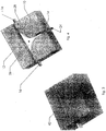
- a primary fibre optic cable conduit 16 is inserted into the channel 12. The installer must determine the location or locations of expected branch points in the network where future (or present) expansion may be forthcoming, for example where a new house or building is planned and it is possible that a cable branch will be required.
- a segment of one wall of the primary fibre optic cable conduit is removed to form a gap 17 in the conduit wall so as to expose the interior of the conduit at this location.
- the gap 17 may be formed at the time the trunk line is installed or subsequently at the time the branch line is added.
- a trunk conduit may be provided which includes pre-existing gaps so as to remove the requirement for cutting away the conduit wall at this point. The gap exposes the fibre optic cables 20 contained within the interior of the conduit.
- a cover plate 36 is provided for covering the gap 17 in the primary fibre optic cable conduit 16.
- the plate may fit onto the conduit with a friction or snap-lock fitting that firmly retains the plate to the conduit.
- the cover plate 36 includes one or more slot-like openings 38 which permit withdrawing a length of a fibre optic cable 20 from the conduit in a manner to be described in detail herein.
- the openings are sealed by removable plugs 40 when they are not in use in a junction location.
- the cover plate and the openings therein are sufficiently long to permit a worker to withdraw the dark cable out from the trunk conduit with reasonable ease. The exact length is matter of design choice and depends in part on the type of optic cable being housed and its rigidity.
- a plurality of fibre optic cables is contained within one or more compartments 22 within the interior of the main fibre optic cable conduit.
- These fibre optic cables 20 installed at the initial stage within the conduit are of two types.
- the cables of the first type are the active or “lit” fibres that are connected to a user location such as a residence or the like.
- the second type comprise unconnected or “dark” fibres that are not yet connected at their distal end to a user, although at their proximal end they remain connected to the central collection point.
- These dark fibres are stored in an elongated fashion within the primary fibre optic cable conduit 16 for future use. They consist of a length of cable which is sufficiently long to reach the expected user location, such as a residence, from a predetermined junction location along the channel.
- the dark fibres are contained within the conduits alongside and in the same manner as the lit fibres. Conveniently, the dark fibres may be marked in a convenient fashion, for example they may always be placed within the same one of the internal compartments, such as the uppermost and/or lowermost compartment, for convenience.
- the dark cables extend lengthwise within the conduit past the junction point for as long as required. More than one such dark cable may be associated with the same gap, in contemplation of multiple users at the same location.
- one or more of the fibre optic cables 20 are dedicated for a specific building along a path defined by the main fibre optic cable conduit 16 and these cables have free ends which can be removed from the main fibre optic cable conduit 16 for delivery to a building.
- the second stage of installing the network occurs when installation of a new branch in a fibre optic cable network is desired for a specific building for example. Often, this may occur a considerable time after the initial stage.
- the conduit is uncovered at the junction location.
- the junction location may comprise a pre-formed gap within the conduit covered by the plate and optionally also the junction housing, described below.
- the junction location may comprise an arbitrary location along the trunk line, in which case the gap is formed within a conduit wall at the time of installing the branch, along with installation of the cover and subsequently installation of the housing.
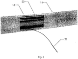
- the dark fibre optic cable 20 designated for the specific building or location is removed from the conduit at this region by withdrawing a length of the dark cable through the opening 38 in the cover plate 36.
- a secondary cut in the surface is made leading from the intersection location to the new user location.
- a secondary or branch optic cable conduit 24 is installed so as to house the dark fibre optic cable 20 and the conduit is laid in the cut towards the new user location.
- the branch conduit is of the same design as the trunk conduit 16, although this is not required.
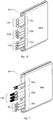
- a junction housing 26 which substantially seals the intersection region.
- the housing 26 is installed within a cavity 28 at the junction location.
- the housing 26 is composed of three lobes comprising two aligned opposing lobes and a central lobe which extends outwardly at a substantially perpendicular angle from the plane of the two aligned lobes.
- the housing comprises in general terms opposing sidewalls that define a central slot having an open bottom and open ends to receive the conduits.
- the two aligned lobes of the housing define a first slot 30 which receives the trunk fibre optic cable conduit 16.
- the slot is a suitable width that the conduit fits snugly therein so as to generally seal the conduit within the housing or alternatively or in additional watertight seals may be provided at all openings.
- the middle lobe includes a second similar slot 32 which receives the branch conduit 24.
- the first and second slots communicate where they intersect so as to form the junction between the trunk and branch conduits.
- the housing 26 includes a bottom cover plate 34 for attachment to the side walls of the housing to fully enclose the housing.
- the junction may comprise multiple secondary lines, such as a four-way branch consisting of the primary conduit and two secondary conduits leading to two dwellings or buildings.
- the housing 26 may be adapted accordingly.
- the housing 26 is made of a rigid, impervious and corrosion-proof substance such as rigid molded plastic.
- a rigid, impervious and corrosion-proof substance such as rigid molded plastic.
- the surface is restored.
- the substrate channels 12, 14 and the cavity 28 are filled with a substrate material or other suitable filling material 42.
- the location of the intersection point may be marked with a suitable small marker embedded in the restored surface such as the marker previously described in the inventor's PCT publication WO/2007/071065 . Conveniently, such a marker may also be employed at the intersection point after the first stage in order to readily locate this point.
- the present invention also includes a method for creating a junction in a fibre optic cable network.
- the method consists of the steps of providing a trunk line that comprises a cable conduit as described above, housing a plurality of optic fibre cables that are all connected at a proximate end to an aggregation point.
- the cables consist of lit fibres that are connected to end users at their distal ends, and dark cables that are yet to be connected to user locations and thus have a free distal end.
- the conduit is uncovered the branch location.
- the conduit may include a pre-formed gap in one or both of its sidewalls or alternatively a gap may be formed at the time the branch is installed.
- the gap is covered with a cover plate and the plug removed to permit removal of the appropriate dark cable, which is then fished from the conduit.
- the freed cable is covered with a branch conduit which is then buried within a branch cut leading to the new user location. The junction is protected by installation of a housing over the trunk and branch lines at this location.
- the junction location will comprise a single branch.
- multiple branches may lead from a single location.
- the number of branches that may be formed from a single trunk is dependent largely upon the number of optic cables that are housed within the trunk conduit. In order to increase this number, it is possible to provide multiple conduits in side by side or stacked relationship (at least for the initial run of trunk line closest to the aggregation point), or alternatively a larger conduit may be provided if desired.
- the fibre optic cable storage and routing system of the present invention is installed in two or more stages which may be separated in time, or performed at generally the same time.
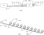
- the system comprises one or more trunk lines 60 to which may be added branch lines 62 leading to user locations.
- the trunk line emanates from a remote distribution point 110 and leads to a local distribution point 112.
- the branches may be added as the need arises, for example as new houses are added to a development or as customers subscribe to a cable service.
- the system further comprises one or more junction locations, which are the intersection points between the trunk line and present and future branches.
- conduit 64 The fibre optic cables within the trunk line 60 are retained within conduit 64, seen in more detail in Figures 8-11 .
- Figures 6 and 7 schematically illustrate a fibre optic cable network, comprising one or more trunk lines 60 and branch lines 62.
- a "line” consists of the optic fibre cables that define a particular function; in some cases as described herein, multiple lines may share a common conduit and substrate channel.
- the various lines intersect at nodes 104, which may consist of trunk/trunk, trunk/branch or branch/branch intersections.
- the branch lines 62 may terminate at an individual user 106, such as a residence or building.
- nodes 104 may be provided at the locations of expected future branch lines, for example, at the locations of future residences or buildings, which may be indicated on an official plan, but which are not yet constructed.
- the trunk line 60 originates from a remote distribution point 110, and terminates at local distribution point 112.
- a plurality of branch lines 62 radiate from the local distribution point. Some of these branch lines retrace the route of the trunk line, and constitute back-haul lines 62a. The back-haul lines terminate at user locations along the trunk line.
- Other branch lines, referred to herein as forward-reaching lines 62b, continue onwardly from the local distribution point 112, and terminate at user locations beyond the local distribution point.
- the back-haul lines 62a and the trunk lines 60 share a common channel 12 and protective conduit 64, as will be described below, for at least a portion of the length of such branch lines until they branch away towards an individual end user.
- the forward-reaching lines 62b share a common trench and conduit for at least a portion of their length, until they branch away towards individual end users.
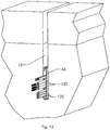
- the trunk lines 60 will comprise a plurality of relatively large trunk cables 120 (seen in Figures 11 and 12 ), each cable holding approximately 72 individual optic fibres.
- the individual blowing tubes 122 (seen in Figures 10-12 ) branch outwardly from the trunk lines, leading towards individual residences, buildings or other customer locations.
- the blowing tubes may be empty or may hold fibre cables that are either lit or dark.
- the cable lines described herein, including the trunk lines and branch lines, are installed within narrow channel-like cuts 12 within a surface. Any given channel 12 may hold therein a trunk line 60, a branch line 62, or a shared line consisting of any combination of trunk and branch lines.
- the channels 12 are typically about 13 mm in width and 150 mm in depth, although a suitable range is approximately 11 mm to 15 mm in width, and 80 mm to 400 mm in depth.
- the relative narrow width of the channels permits them to be formed with a single pass of a saw, for example, of the type described in the present applicant's U.S. Patent Application No. 11/853,489 .
- the branch lines 62a and 62b may comprise a plurality of cable types, including two or more distribution cables, and a plurality of smaller cables, including simplex, duplex, etc., as well as cable blowing tubes.
- the back-haul line 62a shares a conduit and channel with the trunk line 60 in order to simplify construction and assembly of the network.
- a network installation may consist of a trunk line 60, consisting of a cable protector 64 installed within a trench 12, with a plurality of cable types being installed within the cable protector.
- Installation of the trunk line is performed by initially cutting a single narrow trench within a surface, for example using a slab saw.
- a desired cable array is then installed within a cable protector of a suitable length.
- multiple protectors may be supplied for installation in end to end abutting relationship.
- back-haul lines 62a may be installed within different compartments within the same protector 64, including both lit and dark lines.
- the plurality of cable types described above may be installed within the cable protector. Installation of cable within the protector is performed by opening the opposing sides of the protector as described below so as to expose the internal compartments.
- the cables are inlayed within the appropriate compartments; it is not required to thread any cable through the protector, since the cable may be simply inlaid from the surface of the exposed compartments.
- the walls of the protector are then closed and locked together, so as to form a trunk line cable protector having a separated array of cable types, as seen in Figure 10 .
- the cable protector 64 defining the trunk line is then placed within the trench, and suitable connections are made at the cable nodes.
- Branch lines 62 may individually branch away at a plurality of t-intersection nodes, of the type described herein, towards individual users. These nodes may be formed at the time of initial installation of the network, or subsequently in the staged installation process described herein.
- the back-haul lines 62a or forward lines 62b may include within their conduits 64 the dark line segments described herein, arranged to be withdrawn when the need arises in a subsequent stage of installation.
- conduits 64 include two identical separable halves 68a and 68b that may be separated to permit access to the interior so as to install or remove cable therefrom.
- Each conduit 64 is formed from hard plastic material.
- the overall width of the conduits is narrow so as to fit within a channel 12.
- the interior of the conduit 64 is divided into vertically stacked sub-compartments 70a, 70b and 70c by internal dividers formed by divider fins 85 and 86 in order to facilitate cable handling and separation.
- the opposing walls 66a and 66b are retained together with interlocking clasps, as described below, such that the walls fully separate when pried apart.
- conduit 64 may comprise a flexible plastic material that permits the opposing walls to be pried or pulled apart from a longitudinal opening within the top or bottom portions connecting the opposing side walls to expose the interior of the conduit.
- the opposing halves 68a and 68b are fully separable from each other.
- the halves 68a and 68b are identical, but are asymmetric top to bottom so as to lock together when they are inverted relative to each other, such that a first half 68a is oriented in a first direction and the second half 68b is inverted relative to the first half 68a.
- the halves of 68 are retained together by interlocking dividers, base and cap members, as described below.
- Figure 8 illustrates one such half; the opposing half is identical, and mates to the first half when inverted.
- Each half 68a and 68b consists of an outer wall 66 having a generally flat outer surface 74.
- An array of fins protrude from the inner surface of the wall, to mate with opposing fins from a second half.
- the uppermost first fin 80 has an upwardly protruding upper face to form a ridged profile which assists in pushing the conduit into a soft surface.
- a second fin 82 is spaced downwardly from the first fin 80, defining a channel 84 between the two fins 80 and 82 to receive an opposing fin from the second half 68b of the conduit.
- the first and second fins 80 and 82 are dimensioned to fully span the width of the conduit so as to effectively seal the upper and bottom edges of the conduit when closed.
- divider fins 85 and 86 Spaced downwardly from the second fins are divider fins 85 and 86 which likewise span the interior of the conduit and define the internal dividers that separate the conduit into three internal sub-compartments 70a, 70b and 70c (see Figures 10 and 11 ).
- Adjacent to each divider fin is a smaller retainer flange 88, spaced such that a shallow channel 90 is formed between each divider fin and retainer flange, to receive a corresponding fin from the second half 68b.
- the lowermost pair of fins 92 are adjacent to the base of the conduit and are spaced apart to define a lowermost channel 94 to receive a corresponding fin 82 from the opposing half 68b.
- the internal sub-compartments 70a, 70b and 70c are preferably configured to accept a plurality of cables of different types, as will be described below and illustrated in Figures 8-12 , or alternatively are relatively short in height as see in Figures 1 and 2 according to the first embodiment.
- the mating fins described above possess mating ribs 96 and grooves 98 extending lengthwise along the fins, which permit the two halves 68a and 68b to snap-lock together.
- the halves 68a and 68b may be permanently joined together at the bottom or top, with the walls being separated from each other by flexing of the walls (not shown).
- the branch lines 62 may be retained within a similar conduit as described above or alternatively within a conduit having a single internal compartment and a lower top to bottom height, reflective of the reduced number of cables retained therein.
- the sub-compartments 70a, 70b and 70c within the conduit 64 are dimensioned to accept a plurality of cables therein.
- a suitable compartment dimension is 7 mm wide, and 19 mm high, with each compartment extending lengthwise the full length of the protector.
- a compartment having these dimensions conveniently accepts a stacked array of three back-haul cables each having a diameter of 6 mm, or alternatively a larger number of blowing tubes or smaller cables, as seen in Figures 10 and 11 .
- Figure 11 shows a typical arrangement in which the sub-compartments 70a, 70b and 70c retain blowing tubes of several sizes.
- the individual fibres or cables may be either dark or lit, as the need arises.
- the branch lines are installed within one or more narrow trenches, in the same fashion as the trunk line.
Claims (15)
- Système de réseau de fibre optique pour une installation échelonnée vers une pluralité d'emplacements utilisateur présents et futurs, comprenant un point d'agrégation (110), une ligne principale (60) comprenant une pluralité de câbles à fibres optiques (20) menant dudit point d'agrégation, ladite ligne principale comprenant au moins un câble noir possédant une extrémité libre pour un raccordement à un futur emplacement utilisateur, un conduit principal (16, 64) composé de parois latérales opposées (66a, 66b) définissant un espace intérieur (22) entre lesdites parois latérales servant à loger lesdits câbles, caractérisé en ce qu'une longueur dudit câble noir est retenue à l'intérieur dudit espace intérieur, et au moins un emplacement de jonction de dérivation (104) pour desservir un futur emplacement utilisateur, ledit câble noir ayant une longueur suffisante pour atteindre le futur emplacement utilisateur, dans lequel ledit conduit est agencé pour permettre le retrait de ladite longueur dudit câble noir depuis ledit conduit au niveau dudit emplacement de jonction de dérivation lors d'une étape postérieure à l'installation de ladite ligne principale pour former une dérivation menant audit futur emplacement utilisateur ; et caractérisé en outre en ce que ledit conduit principal comprend au moins un séparateur interne (85, 86) définissant une pluralité de sous-compartiments internes (70a, 70b, 70c) s'étendant dans le sens de la longueur pour retenir lesdits câbles et agencés l'un au-dessus de l'autre dans une rangée verticale, ledit conduit principal étant agencé de sorte que la séparation d'au moins une portion de l'une desdites parois latérales expose au moins l'un desdits sous-compartiments, et dans lequel une portion de l'une desdites parois latérales dudit conduit principal au niveau dudit emplacement de jonction de dérivation comprend un cache amovible (36), dans lequel le retrait dudit cache expose l'intérieur dudit conduit principal pour permettre le retrait de ladite longueur de câble noir de celui-ci.
- Système selon la revendication 1, dans lequel ledit conduit principal comprend une pluralité desdits sous-compartiments internes et ledit cache comprend une pluralité d'ouvertures (38) alignées et en communication avec lesdits sous-compartiments internes permettant d'accéder auxdits câbles à fibres optiques dans lesdits sous-compartiments, et comprenant éventuellement des bouchons amovibles (40) pour sélectivement couvrir lesdites ouvertures.
- Système selon la revendication 2, comprenant en outre une ligne de dérivation (62) comprenant un conduit de dérivation (64) comprenant des parois latérales opposées (66a, 66b) définissant un espace intérieur, et dans lequel ledit système comprend en outre un boîtier de protection (26) au niveau dudit emplacement de jonction de dérivation, ledit boîtier comprenant des fentes en intersection (30, 32) agencées pour recevoir lesdits conduits principal et de dérivation de sorte que les espaces intérieurs de ceux-ci sont alignés et en communication entre eux.
- Système selon la revendication 3, dans lequel ledit boîtier est globalement en forme de T et comprend une première fente (30) pour recevoir ladite ligne principale en intersection avec une seconde fente (32) pour recevoir ladite ligne de dérivation.
- Système selon la revendication 1, dans lequel lesdites parois latérales sont maintenues ensemble par des éléments d'assemblage par emboîtement (80, 82, 92, 84, 92).
- Système selon la revendication 1, dans lequel le conduit de câbles (16) comprend deux moitiés séparables identiques (68a et 68b) et asymétriques haut/ bas afin de se verrouiller entre elles lorsqu'une première moitié (68a) est inversée par rapport à une seconde moitié (68b).
- Système selon la revendication 1, dans lequel l'au moins un séparateur interne (85, 86) comprend des ailettes de séparation (85) faisant saillie d'une surface intérieure de la paroi latérale d'une moitié (68a) du conduit de câbles (16) pour couplage avec des ailettes de séparation correspondantes (86) faisant saillie d'une surface intérieure de la paroi latérale de l'autre moitié (68b) du conduit de câbles (16) lorsque les moitiés séparables (68a et 68b) sont verrouillées entre elles.
- Système selon la revendication 7, dans lequel les ailettes (85 et 86) possèdent en outre des nervures (96) et des rainures (98) de conjugaison s'étendant dans le sens de la longueur le long des ailettes qui permettent aux deux moitiés (68a et 68b) de se verrouiller entre elles par clipsage l'une à l'autre.
- Procédé d'installation d'un réseau de câbles à fibre optique sur un support comprenant les étapes consistant à :former au moins un sillon dans ledit support ; caractérisé en cela:fournir un système selon l'une quelconque des revendications 1 à 8 comprenant un conduit principal (60) ;ouvrir une paroi latérale (66a) dudit conduit principal pour exposer lesdits sous-compartiments internes (70a, 70b, 70c) ;coucher une pluralité de câbles à fibres optiques (20) dans lesdits compartiments à partir de la surface des compartiments exposés et fermer lesdites parois latérales ;installer ladite ligne principale dans ledit sillon ;ouvrir une portion de l'une desdites parois latérales dudit conduit pour exposer ladite pluralité de câbles à fibres optiques au niveau d'un emplacement de jonction de dérivation ; etretirer au moins l'une desdites extrémités libres desdits câbles à fibres optiques par ladite ouverture et retirer une longueur dudit câble pour l'installation à un emplacement utilisateur ; dans lequel ladite pluralité desdits câbles à fibres optiques sont retirés dudit conduit de manière échelonnée, dans lequel au moins l'un desdits câbles comprend un câble noir qui est retiré postérieurement à l'installation dudit réseau.
- Procédé selon la revendication 9, comprenant l'étape supplémentaire consistant à coucher un segment dudit câble de dérivation à l'intérieur d'un second protecteur de câble et installer ledit second protecteur de câble avec le câble de dérivation installé dans celui-ci, dans ladite ligne de dérivation.
- Procédé selon la revendication 9, dans lequel lesdits câbles comprennent au moins un câble de distribution et au moins un câble supplémentaire choisi parmi un câble simplex, un câble à tubes lâches et un conduit de soufflage de câbles.
- Procédé selon la revendication 11, dans lequel lesdits câbles comprennent une pluralité de câbles de distribution installés dans un premier desdits compartiments, et une pluralité de câbles de dérivation dits "backhaul" installés dans un second desdits compartiments.
- Procédé selon l'une quelconque des revendications 9-12, dans lequel ledit conduit principal loge des câbles éclairés qui sont raccordés à des utilisateurs finaux à leurs extrémités distales et des câbles noirs qui sont encore à raccorder à des emplacements utilisateur et présentent une extrémité libre distale, dans lequel lesdits câbles noirs sont repêchés du conduit lorsque l'on désire former une dérivation vers un emplacement utilisateur.
- Procédé selon la revendication 13, dans lequel ladite fibre noire est stockée de manière allongée à l'intérieur dudit conduit de câbles pour une utilisation future, ledit câble de fibre noire étant suffisamment long pour atteindre un emplacement utilisateur envisagé à partir d'un emplacement de jonction prédéterminé le long du sillon, ledit câble noir s'étendant dans le sens de la longueur dans le conduit après le point de jonction.
- Procédé selon la revendication 13 ou 14, dans lequel ladite fibre noire est équipée d'un moyen pour la retirer du conduit de câbles principal, tel des cordes à tirer ou des lignes de jetting qui peuvent éventuellement porter un code couleur ou autre moyen facilitant leur repérage.
Applications Claiming Priority (2)
| Application Number | Priority Date | Filing Date | Title |
|---|---|---|---|
| US91607807P | 2007-05-04 | 2007-05-04 | |
| PCT/CA2008/000051 WO2008134848A1 (fr) | 2007-05-04 | 2008-01-11 | Installation d'un réseau à fibre optique |
Publications (3)
| Publication Number | Publication Date |
|---|---|
| EP2153261A1 EP2153261A1 (fr) | 2010-02-17 |
| EP2153261A4 EP2153261A4 (fr) | 2014-05-14 |
| EP2153261B1 true EP2153261B1 (fr) | 2016-12-21 |
Family
ID=39943073
Family Applications (1)
| Application Number | Title | Priority Date | Filing Date |
|---|---|---|---|
| EP08706199.0A Active EP2153261B1 (fr) | 2007-05-04 | 2008-01-11 | Installation d'un réseau à fibre optique |
Country Status (11)
| Country | Link |
|---|---|
| US (1) | US8417083B2 (fr) |
| EP (1) | EP2153261B1 (fr) |
| CN (1) | CN101688961B (fr) |
| AU (1) | AU2008247257A1 (fr) |
| CA (1) | CA2685547C (fr) |
| EA (1) | EA019479B1 (fr) |
| IL (1) | IL201838A0 (fr) |
| NZ (1) | NZ580815A (fr) |
| TW (1) | TW200931091A (fr) |
| WO (1) | WO2008134848A1 (fr) |
| ZA (1) | ZA200907696B (fr) |
Families Citing this family (38)
| Publication number | Priority date | Publication date | Assignee | Title |
|---|---|---|---|---|
| EA019479B1 (ru) | 2007-05-04 | 2014-04-30 | Тераспан Нетворкс Инк. | Монтаж волоконно-оптической сети |
| DE212011100078U1 (de) | 2010-01-26 | 2012-12-12 | Husqvarna Ab | Verlegemaschine |
| MX2012009653A (es) * | 2010-02-21 | 2012-10-01 | Teraspan Networks Inc | Sistema de ducto para componentes de fibra optica. |
| US20110315259A1 (en) * | 2010-06-24 | 2011-12-29 | Google Inc. | Cable edging systems and methods |
| RS58757B1 (sr) | 2010-11-10 | 2019-06-28 | Dellcron Innovation Ab | Postupak za postavljanje najmanje jedne cevi/komunikacionog kabla ispod površine puta u nekoj oblasti |
| US8942956B1 (en) * | 2012-02-16 | 2015-01-27 | Google Inc. | Method and apparatus for building and presenting network designs |
| WO2013130644A1 (fr) | 2012-02-28 | 2013-09-06 | Centurylink Intellectual Property Llc | Conduit apical et procédés d'utilisation de celui-ci |
| EP2847718A4 (fr) | 2012-05-10 | 2016-09-14 | Dellcron Ab | Procédé de mise en place de conduits/câbles et dispositif de planification de leur mise en place |
| EP2972542B1 (fr) | 2013-03-15 | 2018-07-18 | Centurylink Intellectual Property LLC | Technologie de fibre moulée en place |
| US20150037096A1 (en) * | 2013-07-31 | 2015-02-05 | Verizon Patent And Licensing Inc. | Sidewalk trench system |
| US9786997B2 (en) | 2013-08-01 | 2017-10-10 | Centurylink Intellectual Property Llc | Wireless access point in pedestal or hand hole |
| US9780433B2 (en) | 2013-09-06 | 2017-10-03 | Centurylink Intellectual Property Llc | Wireless distribution using cabinets, pedestals, and hand holes |
| US10154325B2 (en) | 2014-02-12 | 2018-12-11 | Centurylink Intellectual Property Llc | Point-to-point fiber insertion |
| US10613284B2 (en) | 2013-10-18 | 2020-04-07 | Centurylink Intellectual Property Llc | Fiber-to-the-Premises (FTTP) methods and systems |
| US10276921B2 (en) | 2013-09-06 | 2019-04-30 | Centurylink Intellectual Property Llc | Radiating closures |
| US10330882B2 (en) | 2013-09-06 | 2019-06-25 | Centurylink Intellectual Property Llc | Apical radiator |
| US10578825B2 (en) | 2013-09-06 | 2020-03-03 | Centurylink Intellectual Property Llc | Apical radiator |
| US10774948B2 (en) | 2013-10-18 | 2020-09-15 | Centurylink Intellectual Property Llc | Apical filler layers |
| US10124509B2 (en) | 2013-11-15 | 2018-11-13 | Vermeer Manufacturing Company | Cutting tooth system |
| US10015570B2 (en) | 2014-02-12 | 2018-07-03 | Centurylink Intellectual Property Llc | Touchless fiber network |
| WO2016077363A1 (fr) | 2014-11-10 | 2016-05-19 | Vermeer Manufacturing Company | Élément de coupe de bord pour tambour de coupe rotatif |
| CN105676380B (zh) * | 2014-11-21 | 2019-07-12 | 泰科电子(上海)有限公司 | 光缆布线系统和光缆连接组件 |
| US20160209616A1 (en) * | 2015-01-19 | 2016-07-21 | Corning Optical Communications LLC | Roadway expansion joint for fiber optic cable deployment |
| US9742172B2 (en) | 2015-01-30 | 2017-08-22 | Centurylink Intellectual Property Llc | MediaLink interconnection box |
| AU2017300264A1 (en) * | 2016-07-18 | 2019-02-21 | Corning Research & Development Corporation | Distribution cabling tape and system |
| US10249103B2 (en) | 2016-08-02 | 2019-04-02 | Centurylink Intellectual Property Llc | System and method for implementing added services for OBD2 smart vehicle connection |
| US10110272B2 (en) | 2016-08-24 | 2018-10-23 | Centurylink Intellectual Property Llc | Wearable gesture control device and method |
| US10687377B2 (en) | 2016-09-20 | 2020-06-16 | Centurylink Intellectual Property Llc | Universal wireless station for multiple simultaneous wireless services |
| US10150471B2 (en) | 2016-12-23 | 2018-12-11 | Centurylink Intellectual Property Llc | Smart vehicle apparatus, system, and method |
| US10193981B2 (en) | 2016-12-23 | 2019-01-29 | Centurylink Intellectual Property Llc | Internet of things (IoT) self-organizing network |
| US10222773B2 (en) | 2016-12-23 | 2019-03-05 | Centurylink Intellectual Property Llc | System, apparatus, and method for implementing one or more internet of things (IoT) capable devices embedded within a roadway structure for performing various tasks |
| US10146024B2 (en) | 2017-01-10 | 2018-12-04 | Centurylink Intellectual Property Llc | Apical conduit method and system |
| US10437001B1 (en) * | 2018-09-20 | 2019-10-08 | The United States Of America As Represented By The Secretary Of The Navy | Fiber optic drogue and cable retraction spool |
| CA3142275A1 (fr) | 2019-06-04 | 2020-12-10 | Ppc Broadband Fiber Ltd. | Installation de cable a fibres optiques de rappel vers l'arriere pour unites de logement multiples |
| DE102019117612B4 (de) * | 2019-06-28 | 2021-01-21 | Deutsche Telekom Ag | Kabel-Rohrverband, Verfahren zur Herstellung und Verlegung |
| IT202100007970A1 (it) * | 2021-03-31 | 2022-10-01 | Paolo AGAZZONE | Dispositivo per la disposizione di cavi in fibra ottica nel terreno. |
| DE102021128334B4 (de) | 2021-10-29 | 2023-12-14 | Deutsche Telekom Ag | Kabelverbund |
| DE102022117616B4 (de) | 2022-07-14 | 2024-02-01 | Deutsche Telekom Ag | Proaktive Verlegung eines Kabel-Rohrverbandes für Glasfaserkabel |
Family Cites Families (13)
| Publication number | Priority date | Publication date | Assignee | Title |
|---|---|---|---|---|
| US5336849A (en) * | 1992-01-17 | 1994-08-09 | The Wiremold Company | Raceway assembly for power and communications conductors |
| US5788414A (en) | 1995-06-02 | 1998-08-04 | Bell Atlantic Network Services, Inc. | Fiber optic saddle |
| AR004288A1 (es) | 1995-11-13 | 1998-11-04 | Siemens Ag | Estructura de instalación de cable de fibras ópticas. |
| US5898811A (en) * | 1997-01-22 | 1999-04-27 | Lucent Technologies, Inc. | Multi-fiber optical cable |
| US6262371B1 (en) * | 1999-06-23 | 2001-07-17 | Marc Talon, Inc. | Method and apparatus for dividing a conduit into compartments |
| CN2423586Y (zh) * | 2000-03-29 | 2001-03-14 | 甄青 | 电缆、光缆用多孔管 |
| US6965302B2 (en) * | 2000-04-14 | 2005-11-15 | Current Technologies, Llc | Power line communication system and method of using the same |
| CA2337284A1 (fr) * | 2001-02-15 | 2002-08-15 | Teraspan Networks Inc. | Installation de reseau de cables optiques en surface |
| US7027697B2 (en) * | 2001-12-28 | 2006-04-11 | Pirelli Communications Cables And Systems Usa, Llc | Cable having conduits for receiving optical fibers |
| US6702510B2 (en) * | 2002-01-03 | 2004-03-09 | Ede Holdings, Inc. | Utility sidewalk |
| US6666561B1 (en) * | 2002-10-28 | 2003-12-23 | Hewlett-Packard Development Company, L.P. | Continuously variable analog micro-mirror device |
| AU2004257311B2 (en) * | 2003-07-17 | 2009-07-02 | Teraspan Networks Inc. | Junction box housings for surface inlaid fibre optic network installations |
| EA019479B1 (ru) | 2007-05-04 | 2014-04-30 | Тераспан Нетворкс Инк. | Монтаж волоконно-оптической сети |
-
2008
- 2008-01-11 EA EA200901386A patent/EA019479B1/ru not_active IP Right Cessation
- 2008-01-11 NZ NZ580815A patent/NZ580815A/xx not_active IP Right Cessation
- 2008-01-11 EP EP08706199.0A patent/EP2153261B1/fr active Active
- 2008-01-11 CN CN200880023030.7A patent/CN101688961B/zh not_active Expired - Fee Related
- 2008-01-11 AU AU2008247257A patent/AU2008247257A1/en not_active Abandoned
- 2008-01-11 US US12/598,846 patent/US8417083B2/en active Active
- 2008-01-11 CA CA2685547A patent/CA2685547C/fr active Active
- 2008-01-11 WO PCT/CA2008/000051 patent/WO2008134848A1/fr active Application Filing
- 2008-08-08 TW TW097130445A patent/TW200931091A/zh unknown
-
2009
- 2009-10-29 IL IL201838A patent/IL201838A0/en unknown
- 2009-11-03 ZA ZA200907696A patent/ZA200907696B/xx unknown
Non-Patent Citations (1)
| Title |
|---|
| None * |
Also Published As
| Publication number | Publication date |
|---|---|
| CA2685547C (fr) | 2017-02-14 |
| US20100086254A1 (en) | 2010-04-08 |
| CN101688961B (zh) | 2012-11-28 |
| ZA200907696B (en) | 2010-06-30 |
| CA2685547A1 (fr) | 2008-11-13 |
| EP2153261A1 (fr) | 2010-02-17 |
| IL201838A0 (en) | 2010-06-16 |
| NZ580815A (en) | 2012-11-30 |
| US8417083B2 (en) | 2013-04-09 |
| AU2008247257A1 (en) | 2008-11-13 |
| WO2008134848A1 (fr) | 2008-11-13 |
| EP2153261A4 (fr) | 2014-05-14 |
| CN101688961A (zh) | 2010-03-31 |
| EA019479B1 (ru) | 2014-04-30 |
| TW200931091A (en) | 2009-07-16 |
| EA200901386A1 (ru) | 2010-04-30 |
Similar Documents
| Publication | Publication Date | Title |
|---|---|---|
| EP2153261B1 (fr) | Installation d'un réseau à fibre optique | |
| EP1360536B1 (fr) | Installation de câbles à fibres optiques dans un substrat mou | |
| AU2002234447A1 (en) | Subsurface fibre optic cable network installation | |
| EP2338213B1 (fr) | Pose de câbles de réseau dans des canalisations d adduction d eau | |
| AU2014253505B2 (en) | Fiber Optic Network Installation | |
| CN102841416A (zh) | 挂壁式光分路器箱及其使用方法 | |
| CA2348062A1 (fr) | Methode d'installation d'un systeme de conduits pour fibres optiques | |
| US9678297B2 (en) | Conduit system for an optic waveguide and method for installing a conduit system for an optic waveguide | |
| CN202102155U (zh) | 挂壁式光分路器箱 | |
| AU2006200987B2 (en) | Subsurface fibre optic cable network installation | |
| WO2012051673A1 (fr) | Déploiement d'un système réticulé | |
| US20230204896A1 (en) | Optical cable laying method | |
| CA2438488C (fr) | Installation de reseau de cables a fibres optiques souterrain | |
| Slavin et al. | Buried Duct Network for Utility Cables Along Roads and Highways: Results of Field Trials |
Legal Events
| Date | Code | Title | Description |
|---|---|---|---|
| PUAI | Public reference made under article 153(3) epc to a published international application that has entered the european phase |
Free format text: ORIGINAL CODE: 0009012 |
|
| 17P | Request for examination filed |
Effective date: 20091202 |
|
| AK | Designated contracting states |
Kind code of ref document: A1 Designated state(s): AT BE BG CH CY CZ DE DK EE ES FI FR GB GR HR HU IE IS IT LI LT LU LV MC MT NL NO PL PT RO SE SI SK TR |
|
| AX | Request for extension of the european patent |
Extension state: AL BA MK RS |
|
| RAX | Requested extension states of the european patent have changed |
Extension state: AL Payment date: 20091202 |
|
| A4 | Supplementary search report drawn up and despatched |
Effective date: 20140414 |
|
| RIC1 | Information provided on ipc code assigned before grant |
Ipc: G02B 6/50 20060101AFI20140408BHEP |
|
| GRAP | Despatch of communication of intention to grant a patent |
Free format text: ORIGINAL CODE: EPIDOSNIGR1 |
|
| INTG | Intention to grant announced |
Effective date: 20151109 |
|
| GRAS | Grant fee paid |
Free format text: ORIGINAL CODE: EPIDOSNIGR3 |
|
| INTC | Intention to grant announced (deleted) | ||
| GRAP | Despatch of communication of intention to grant a patent |
Free format text: ORIGINAL CODE: EPIDOSNIGR1 |
|
| GRAS | Grant fee paid |
Free format text: ORIGINAL CODE: EPIDOSNIGR3 |
|
| GRAA | (expected) grant |
Free format text: ORIGINAL CODE: 0009210 |
|
| INTG | Intention to grant announced |
Effective date: 20161026 |
|
| AK | Designated contracting states |
Kind code of ref document: B1 Designated state(s): AT BE BG CH CY CZ DE DK EE ES FI FR GB GR HR HU IE IS IT LI LT LU LV MC MT NL NO PL PT RO SE SI SK TR |
|
| AX | Request for extension of the european patent |
Extension state: AL |
|
| REG | Reference to a national code |
Ref country code: GB Ref legal event code: FG4D |
|
| REG | Reference to a national code |
Ref country code: CH Ref legal event code: EP |
|
| REG | Reference to a national code |
Ref country code: IE Ref legal event code: FG4D |
|
| REG | Reference to a national code |
Ref country code: AT Ref legal event code: REF Ref document number: 855975 Country of ref document: AT Kind code of ref document: T Effective date: 20170115 |
|
| REG | Reference to a national code |
Ref country code: DE Ref legal event code: R096 Ref document number: 602008047972 Country of ref document: DE |
|
| PG25 | Lapsed in a contracting state [announced via postgrant information from national office to epo] |
Ref country code: LV Free format text: LAPSE BECAUSE OF FAILURE TO SUBMIT A TRANSLATION OF THE DESCRIPTION OR TO PAY THE FEE WITHIN THE PRESCRIBED TIME-LIMIT Effective date: 20161221 |
|
| REG | Reference to a national code |
Ref country code: FR Ref legal event code: PLFP Year of fee payment: 10 |
|
| REG | Reference to a national code |
Ref country code: LT Ref legal event code: MG4D |
|
| REG | Reference to a national code |
Ref country code: NL Ref legal event code: MP Effective date: 20161221 |
|
| PG25 | Lapsed in a contracting state [announced via postgrant information from national office to epo] |
Ref country code: NO Free format text: LAPSE BECAUSE OF FAILURE TO SUBMIT A TRANSLATION OF THE DESCRIPTION OR TO PAY THE FEE WITHIN THE PRESCRIBED TIME-LIMIT Effective date: 20170321 Ref country code: GR Free format text: LAPSE BECAUSE OF FAILURE TO SUBMIT A TRANSLATION OF THE DESCRIPTION OR TO PAY THE FEE WITHIN THE PRESCRIBED TIME-LIMIT Effective date: 20170322 Ref country code: LT Free format text: LAPSE BECAUSE OF FAILURE TO SUBMIT A TRANSLATION OF THE DESCRIPTION OR TO PAY THE FEE WITHIN THE PRESCRIBED TIME-LIMIT Effective date: 20161221 Ref country code: SE Free format text: LAPSE BECAUSE OF FAILURE TO SUBMIT A TRANSLATION OF THE DESCRIPTION OR TO PAY THE FEE WITHIN THE PRESCRIBED TIME-LIMIT Effective date: 20161221 |
|
| PGFP | Annual fee paid to national office [announced via postgrant information from national office to epo] |
Ref country code: FR Payment date: 20170322 Year of fee payment: 10 |
|
| REG | Reference to a national code |
Ref country code: AT Ref legal event code: MK05 Ref document number: 855975 Country of ref document: AT Kind code of ref document: T Effective date: 20161221 |
|
| PG25 | Lapsed in a contracting state [announced via postgrant information from national office to epo] |
Ref country code: FI Free format text: LAPSE BECAUSE OF FAILURE TO SUBMIT A TRANSLATION OF THE DESCRIPTION OR TO PAY THE FEE WITHIN THE PRESCRIBED TIME-LIMIT Effective date: 20161221 Ref country code: BE Free format text: LAPSE BECAUSE OF NON-PAYMENT OF DUE FEES Effective date: 20170131 Ref country code: HR Free format text: LAPSE BECAUSE OF FAILURE TO SUBMIT A TRANSLATION OF THE DESCRIPTION OR TO PAY THE FEE WITHIN THE PRESCRIBED TIME-LIMIT Effective date: 20161221 |
|
| PGFP | Annual fee paid to national office [announced via postgrant information from national office to epo] |
Ref country code: GB Payment date: 20170316 Year of fee payment: 10 |
|
| PG25 | Lapsed in a contracting state [announced via postgrant information from national office to epo] |
Ref country code: NL Free format text: LAPSE BECAUSE OF FAILURE TO SUBMIT A TRANSLATION OF THE DESCRIPTION OR TO PAY THE FEE WITHIN THE PRESCRIBED TIME-LIMIT Effective date: 20161221 |
|
| PG25 | Lapsed in a contracting state [announced via postgrant information from national office to epo] |
Ref country code: EE Free format text: LAPSE BECAUSE OF FAILURE TO SUBMIT A TRANSLATION OF THE DESCRIPTION OR TO PAY THE FEE WITHIN THE PRESCRIBED TIME-LIMIT Effective date: 20161221 Ref country code: IS Free format text: LAPSE BECAUSE OF FAILURE TO SUBMIT A TRANSLATION OF THE DESCRIPTION OR TO PAY THE FEE WITHIN THE PRESCRIBED TIME-LIMIT Effective date: 20170421 Ref country code: RO Free format text: LAPSE BECAUSE OF FAILURE TO SUBMIT A TRANSLATION OF THE DESCRIPTION OR TO PAY THE FEE WITHIN THE PRESCRIBED TIME-LIMIT Effective date: 20161221 Ref country code: CZ Free format text: LAPSE BECAUSE OF FAILURE TO SUBMIT A TRANSLATION OF THE DESCRIPTION OR TO PAY THE FEE WITHIN THE PRESCRIBED TIME-LIMIT Effective date: 20161221 Ref country code: SK Free format text: LAPSE BECAUSE OF FAILURE TO SUBMIT A TRANSLATION OF THE DESCRIPTION OR TO PAY THE FEE WITHIN THE PRESCRIBED TIME-LIMIT Effective date: 20161221 |
|
| REG | Reference to a national code |
Ref country code: DE Ref legal event code: R119 Ref document number: 602008047972 Country of ref document: DE |
|
| PG25 | Lapsed in a contracting state [announced via postgrant information from national office to epo] |
Ref country code: PL Free format text: LAPSE BECAUSE OF FAILURE TO SUBMIT A TRANSLATION OF THE DESCRIPTION OR TO PAY THE FEE WITHIN THE PRESCRIBED TIME-LIMIT Effective date: 20161221 Ref country code: PT Free format text: LAPSE BECAUSE OF FAILURE TO SUBMIT A TRANSLATION OF THE DESCRIPTION OR TO PAY THE FEE WITHIN THE PRESCRIBED TIME-LIMIT Effective date: 20170421 Ref country code: BG Free format text: LAPSE BECAUSE OF FAILURE TO SUBMIT A TRANSLATION OF THE DESCRIPTION OR TO PAY THE FEE WITHIN THE PRESCRIBED TIME-LIMIT Effective date: 20170321 Ref country code: IT Free format text: LAPSE BECAUSE OF FAILURE TO SUBMIT A TRANSLATION OF THE DESCRIPTION OR TO PAY THE FEE WITHIN THE PRESCRIBED TIME-LIMIT Effective date: 20161221 Ref country code: AT Free format text: LAPSE BECAUSE OF FAILURE TO SUBMIT A TRANSLATION OF THE DESCRIPTION OR TO PAY THE FEE WITHIN THE PRESCRIBED TIME-LIMIT Effective date: 20161221 Ref country code: ES Free format text: LAPSE BECAUSE OF FAILURE TO SUBMIT A TRANSLATION OF THE DESCRIPTION OR TO PAY THE FEE WITHIN THE PRESCRIBED TIME-LIMIT Effective date: 20161221 Ref country code: BE Free format text: LAPSE BECAUSE OF FAILURE TO SUBMIT A TRANSLATION OF THE DESCRIPTION OR TO PAY THE FEE WITHIN THE PRESCRIBED TIME-LIMIT Effective date: 20161221 |
|
| REG | Reference to a national code |
Ref country code: CH Ref legal event code: PL |
|
| PG25 | Lapsed in a contracting state [announced via postgrant information from national office to epo] |
Ref country code: MC Free format text: LAPSE BECAUSE OF FAILURE TO SUBMIT A TRANSLATION OF THE DESCRIPTION OR TO PAY THE FEE WITHIN THE PRESCRIBED TIME-LIMIT Effective date: 20161221 |
|
| PLBE | No opposition filed within time limit |
Free format text: ORIGINAL CODE: 0009261 |
|
| STAA | Information on the status of an ep patent application or granted ep patent |
Free format text: STATUS: NO OPPOSITION FILED WITHIN TIME LIMIT |
|
| PG25 | Lapsed in a contracting state [announced via postgrant information from national office to epo] |
Ref country code: LI Free format text: LAPSE BECAUSE OF NON-PAYMENT OF DUE FEES Effective date: 20170131 Ref country code: CH Free format text: LAPSE BECAUSE OF NON-PAYMENT OF DUE FEES Effective date: 20170131 |
|
| REG | Reference to a national code |
Ref country code: IE Ref legal event code: MM4A |
|
| 26N | No opposition filed |
Effective date: 20170922 |
|
| PG25 | Lapsed in a contracting state [announced via postgrant information from national office to epo] |
Ref country code: DE Free format text: LAPSE BECAUSE OF NON-PAYMENT OF DUE FEES Effective date: 20170801 Ref country code: LU Free format text: LAPSE BECAUSE OF NON-PAYMENT OF DUE FEES Effective date: 20170111 Ref country code: DK Free format text: LAPSE BECAUSE OF FAILURE TO SUBMIT A TRANSLATION OF THE DESCRIPTION OR TO PAY THE FEE WITHIN THE PRESCRIBED TIME-LIMIT Effective date: 20161221 |
|
| PG25 | Lapsed in a contracting state [announced via postgrant information from national office to epo] |
Ref country code: IE Free format text: LAPSE BECAUSE OF NON-PAYMENT OF DUE FEES Effective date: 20170111 Ref country code: SI Free format text: LAPSE BECAUSE OF FAILURE TO SUBMIT A TRANSLATION OF THE DESCRIPTION OR TO PAY THE FEE WITHIN THE PRESCRIBED TIME-LIMIT Effective date: 20161221 |
|
| GBPC | Gb: european patent ceased through non-payment of renewal fee |
Effective date: 20180111 |
|
| PG25 | Lapsed in a contracting state [announced via postgrant information from national office to epo] |
Ref country code: MT Free format text: LAPSE BECAUSE OF NON-PAYMENT OF DUE FEES Effective date: 20170111 |
|
| PG25 | Lapsed in a contracting state [announced via postgrant information from national office to epo] |
Ref country code: FR Free format text: LAPSE BECAUSE OF NON-PAYMENT OF DUE FEES Effective date: 20180131 |
|
| REG | Reference to a national code |
Ref country code: FR Ref legal event code: ST Effective date: 20180928 |
|
| PG25 | Lapsed in a contracting state [announced via postgrant information from national office to epo] |
Ref country code: GB Free format text: LAPSE BECAUSE OF NON-PAYMENT OF DUE FEES Effective date: 20180111 |
|
| PG25 | Lapsed in a contracting state [announced via postgrant information from national office to epo] |
Ref country code: HU Free format text: LAPSE BECAUSE OF FAILURE TO SUBMIT A TRANSLATION OF THE DESCRIPTION OR TO PAY THE FEE WITHIN THE PRESCRIBED TIME-LIMIT; INVALID AB INITIO Effective date: 20080111 |
|
| PG25 | Lapsed in a contracting state [announced via postgrant information from national office to epo] |
Ref country code: CY Free format text: LAPSE BECAUSE OF NON-PAYMENT OF DUE FEES Effective date: 20161221 |
|
| PG25 | Lapsed in a contracting state [announced via postgrant information from national office to epo] |
Ref country code: TR Free format text: LAPSE BECAUSE OF FAILURE TO SUBMIT A TRANSLATION OF THE DESCRIPTION OR TO PAY THE FEE WITHIN THE PRESCRIBED TIME-LIMIT Effective date: 20161221 |