EP2152597B1 - Packages having fluid-filled chamber closures - Google Patents
Packages having fluid-filled chamber closures Download PDFInfo
- Publication number
- EP2152597B1 EP2152597B1 EP08747792.3A EP08747792A EP2152597B1 EP 2152597 B1 EP2152597 B1 EP 2152597B1 EP 08747792 A EP08747792 A EP 08747792A EP 2152597 B1 EP2152597 B1 EP 2152597B1
- Authority
- EP
- European Patent Office
- Prior art keywords
- package
- fluid
- chambers
- closure
- filled
- Prior art date
- Legal status (The legal status is an assumption and is not a legal conclusion. Google has not performed a legal analysis and makes no representation as to the accuracy of the status listed.)
- Active
Links
- 239000012530 fluid Substances 0.000 title claims description 230
- 239000000463 material Substances 0.000 claims description 33
- 239000000853 adhesive Substances 0.000 claims description 6
- 230000001070 adhesive effect Effects 0.000 claims description 6
- 239000010902 straw Substances 0.000 claims description 3
- 230000003068 static effect Effects 0.000 claims description 2
- 238000007789 sealing Methods 0.000 description 29
- 230000007246 mechanism Effects 0.000 description 27
- 230000004888 barrier function Effects 0.000 description 22
- 238000000034 method Methods 0.000 description 12
- 230000033001 locomotion Effects 0.000 description 10
- 239000007789 gas Substances 0.000 description 8
- 238000004519 manufacturing process Methods 0.000 description 8
- 239000007788 liquid Substances 0.000 description 7
- QVGXLLKOCUKJST-UHFFFAOYSA-N atomic oxygen Chemical compound [O] QVGXLLKOCUKJST-UHFFFAOYSA-N 0.000 description 6
- 239000001301 oxygen Substances 0.000 description 6
- 229910052760 oxygen Inorganic materials 0.000 description 6
- -1 polyethylene Polymers 0.000 description 6
- 238000012546 transfer Methods 0.000 description 6
- 239000004698 Polyethylene Substances 0.000 description 5
- 238000004806 packaging method and process Methods 0.000 description 5
- 230000036961 partial effect Effects 0.000 description 5
- 229920000573 polyethylene Polymers 0.000 description 5
- 238000013461 design Methods 0.000 description 4
- 238000005304 joining Methods 0.000 description 4
- 230000000670 limiting effect Effects 0.000 description 4
- 230000009471 action Effects 0.000 description 3
- 238000013459 approach Methods 0.000 description 3
- 230000015572 biosynthetic process Effects 0.000 description 3
- 230000000694 effects Effects 0.000 description 3
- 230000014759 maintenance of location Effects 0.000 description 3
- 230000013011 mating Effects 0.000 description 3
- 230000000750 progressive effect Effects 0.000 description 3
- 230000001681 protective effect Effects 0.000 description 3
- 239000007787 solid Substances 0.000 description 3
- 238000003860 storage Methods 0.000 description 3
- 229920000219 Ethylene vinyl alcohol Polymers 0.000 description 2
- 239000004677 Nylon Substances 0.000 description 2
- 230000033228 biological regulation Effects 0.000 description 2
- 238000004891 communication Methods 0.000 description 2
- 238000005520 cutting process Methods 0.000 description 2
- 229920001778 nylon Polymers 0.000 description 2
- 229920000728 polyester Polymers 0.000 description 2
- 238000003825 pressing Methods 0.000 description 2
- 230000008569 process Effects 0.000 description 2
- 230000001105 regulatory effect Effects 0.000 description 2
- 239000004743 Polypropylene Substances 0.000 description 1
- 229920001328 Polyvinylidene chloride Polymers 0.000 description 1
- ATJFFYVFTNAWJD-UHFFFAOYSA-N Tin Chemical compound [Sn] ATJFFYVFTNAWJD-UHFFFAOYSA-N 0.000 description 1
- 230000002411 adverse Effects 0.000 description 1
- 239000003570 air Substances 0.000 description 1
- 230000009286 beneficial effect Effects 0.000 description 1
- 230000005540 biological transmission Effects 0.000 description 1
- 238000010276 construction Methods 0.000 description 1
- 238000011109 contamination Methods 0.000 description 1
- 230000008602 contraction Effects 0.000 description 1
- 230000008878 coupling Effects 0.000 description 1
- 238000010168 coupling process Methods 0.000 description 1
- 238000005859 coupling reaction Methods 0.000 description 1
- 230000001419 dependent effect Effects 0.000 description 1
- 238000011161 development Methods 0.000 description 1
- 230000018109 developmental process Effects 0.000 description 1
- 230000009977 dual effect Effects 0.000 description 1
- UFRKOOWSQGXVKV-UHFFFAOYSA-N ethene;ethenol Chemical compound C=C.OC=C UFRKOOWSQGXVKV-UHFFFAOYSA-N 0.000 description 1
- 239000004715 ethylene vinyl alcohol Substances 0.000 description 1
- 238000009459 flexible packaging Methods 0.000 description 1
- 239000011888 foil Substances 0.000 description 1
- 230000002706 hydrostatic effect Effects 0.000 description 1
- 238000003754 machining Methods 0.000 description 1
- 239000002184 metal Substances 0.000 description 1
- 230000005012 migration Effects 0.000 description 1
- 238000013508 migration Methods 0.000 description 1
- 230000000116 mitigating effect Effects 0.000 description 1
- 235000019645 odor Nutrition 0.000 description 1
- 230000003647 oxidation Effects 0.000 description 1
- 238000007254 oxidation reaction Methods 0.000 description 1
- 230000035699 permeability Effects 0.000 description 1
- 239000004033 plastic Substances 0.000 description 1
- 229920003023 plastic Polymers 0.000 description 1
- 229920000642 polymer Polymers 0.000 description 1
- 229920001155 polypropylene Polymers 0.000 description 1
- 239000005033 polyvinylidene chloride Substances 0.000 description 1
- 230000004224 protection Effects 0.000 description 1
- 230000002787 reinforcement Effects 0.000 description 1
- 239000000565 sealant Substances 0.000 description 1
- 238000007493 shaping process Methods 0.000 description 1
- XLYOFNOQVPJJNP-UHFFFAOYSA-N water Substances O XLYOFNOQVPJJNP-UHFFFAOYSA-N 0.000 description 1
Images


Classifications
-
- B—PERFORMING OPERATIONS; TRANSPORTING
- B65—CONVEYING; PACKING; STORING; HANDLING THIN OR FILAMENTARY MATERIAL
- B65D—CONTAINERS FOR STORAGE OR TRANSPORT OF ARTICLES OR MATERIALS, e.g. BAGS, BARRELS, BOTTLES, BOXES, CANS, CARTONS, CRATES, DRUMS, JARS, TANKS, HOPPERS, FORWARDING CONTAINERS; ACCESSORIES, CLOSURES, OR FITTINGS THEREFOR; PACKAGING ELEMENTS; PACKAGES
- B65D33/00—Details of, or accessories for, sacks or bags
- B65D33/16—End- or aperture-closing arrangements or devices
- B65D33/25—Riveting; Dovetailing; Screwing; using press buttons or slide fasteners
- B65D33/2508—Riveting; Dovetailing; Screwing; using press buttons or slide fasteners using slide fasteners with interlocking members having a substantially uniform section throughout the length of the fastener; Sliders therefor
- B65D33/2541—Riveting; Dovetailing; Screwing; using press buttons or slide fasteners using slide fasteners with interlocking members having a substantially uniform section throughout the length of the fastener; Sliders therefor characterised by the slide fastener, e.g. adapted to interlock with a sheet between the interlocking members having sections of particular shape
Definitions
- the present invention relates generally to flexible packaging and, more particularly, to packages, and methods for manufacturing and using packages, having fluid actuated closures and secondary closures or seals.
- Conventional flexible packages generally include external or integrated sliding means or other similar devices designed to allow a user to selectively gain access into the pouch or package.
- non-integrated, twist ties and other tying means have also been used to close an open-end portion of a flexible package. These devices often require the manufacturing of additional and often costly materials and/or devices into the packages.
- press-to-close closure mechanisms are sometimes difficult to align when attempting to mate together, often causing a failure of a true closure.
- small pieces of the product can get caught in tracks of the mating interlocking members, causing a breach across the interlocking components and hampering any positive seal.
- the compromise of the integrity of the seal between the mating locking components may also be caused by localized crushing (e.g., proximate side seal) of the interlocking members during manufacturing, shipping, handling, and use by the consumer.
- the localized crushing need only be enough to plastically deform either of the interlocking members to cause a leak.
- zipper-type closure mechanisms merely serve to close off the top portion of the package by pulling or forcing together the top portions of the front and back panels of the package.
- This zipper-type closure mechanism has two significant drawbacks. First, it reduces the internal holding volume of the package since, in a closed position, side gussets of the package are forced to contact at an end proximate the access opening. Second, a space or gap can remain when the zipper-type closure mechanism is in its closed position. The gap permits air to flow in and out of the package.
- the zipper-type closures may be easier for some consumers to operate, and may have a more positive closure with respect to the press-to-close closure mechanism, they can be expensive and, like the press to close closure mechanisms, often do not create an ideal barrier after the package has been opened by the consumer for the first time.
- WO 2006/052800 A2 discloses a flexible package with the features according to the preamble of claim 1.
- a purpose of the present invention is to allow for a package, such as a flexible package, to be opened and reclosed with a simple squeezing motion, to maintain a higher barrier against oxygen transmission after the package has been initially opened by the consumer, and/or to provide a one-way release valve, if desired.
- the various embodiments and teachings provided herein can also be employed with a rigid or semi-rigid package.
- Embodiments of the present invention are directed to device for sealing a package that generally includes at least one front and back member joined at least partially together, the members each defining the boundary of an access opening.
- the members may be panels of a package, the package defining an interior cavity accessible through the access opening.
- the interior is capable of storing and dispensing product and other objects or materials.
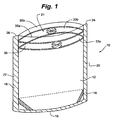
- the package 10 generally includes a front panel portion 12, a back panel portion 14. Further, a bottom panel portion 15, gusseted or non-gusseted, can be included, especially in those embodiments defining a stand up package.
- the joining and/or shaping of the panels 12, 14, 15, generally define an inner cavity 21 having an adjustable internal volumetric capacity.
- the inner cavity 21 is capable of storing, transporting and/or dispensing product or other objects and material therein.
- Side panel portions (not shown), gusseted or non-gusseted, may also be included.
- the panel portions 12-15 are often referred to as webs, films or layers.
- the package panel portions 12-15 are generally constructed of a flexible sheet material such as polyethylene, polyester, metal foil, polypropylene, or polyethylenes laminated with other materials such as nylon, polyester, and like films.
- a material having preferred sealing characteristics can be joined or bonded to a material having a different preferred characteristic (i.e., beneficial oxygen barrier properties).
- the package is to be formed into a stand-up pouch, but it could be a pouch that displays lying down, or in other package and pouch shapes and configurations known to one skilled in the art.
- the front panel portion 12 and the back panel portion 14 will be formed of one contiguous web material.
- at least one of the panel portions 12-15 can be distinct web materials joined or sealed to other respective panel portions to form the package 10.
- the front panel portion 12 and the back panel portion 14 can be joined to each other from distinct non-contiguous web sheets of material, and one of said panel portions 12-14 can further extend to define the bottom panel portion 15.
- the bottom panel portion 15 in the various configurations forming a stand up pouch can include a gusset known to those skilled in the art to further promote operative expansion and contraction of the package 10 and its respective capacity in accordance with the receipt and removal of material within the package 10.
- the front panel portion 12 generally includes a first front longitudinal edge 20 and a second front longitudinal edge 22. Both of said front panel longitudinal edges 20, 22 may be substantially parallel to each other and extend along the longitudinal length of the front panel portion 12.
- the back panel portion 14 generally includes a first back longitudinal edge 24 and a second back longitudinal edge 26, also substantially parallel to each other and spanning the longitudinal length of the back panel portion 14.
- first front longitudinal edge 20 can be sealably joined to the first back longitudinal edge 24 along the length of the edges 20, 24 to form first side seal 16.
- second front longitudinal edge 22 can be sealably joined to the second back longitudinal edge 26 along the length of edges 22, 26 to form second side seal 18.
- These side seals 16, 18 generally define the side boundaries of the package 10 and can be sealably joined using heat, adhesive, and other bonding techniques known to one of ordinary skill in the art.
- the flexible package 10 includes a fluid actuated closure 30 attached to or integrated to the flexible package 10 to permit a user to selectively reclose the access opening 19.
- the fluid actuated closure 30 includes at least one first web barrier or layer 32a joined to an inner surface of the front panel portion 12 of the package 10 and at least one second web barrier or layer 32b joined to an inner surface of the back panel portion 14 of the package 10, such that the first 32a and second 32b web barriers are generally opposed (e.g. Fig. 3 ).
- only one web barrier or layer 32a joined to an interior of a panel portion e.g., front panel portion 12, as depicted in Fig.
- the barrier 32a confronts the interior of the opposing panel portion (e.g., back panel portion 14) or some other structure of the package 10 to provide selective opening, closing of the package 10 through sealing of the access opening 19 as described herein.
- the access opening 19 and fluid actuate closure 30 are positioned along a limited portion of the package (e.g., an opening into a moist toilette container or package), the closure permits a liquid and air seal to preserve the contents after the initial opening of the package.
- the front 12 and back 14 panel portions and the first 32a and second 32b web barriers can define at least two fluid chambers or tubes 33a and 33b that extend generally along a long axis of the access opening 19, generally transverse to the side seals.
- the fluid chambers 33a and 33b may be a laminate formed by trapping or positioning a barrier film between two layers of a sealant film, preferably a Nylon or EVOH barrier film co-extruded between two layers of polyethylene.
- the fluid chambers 33a and 33b are sealed into the top section of the package 10 where typically air, or gas, liquid, or a similar item, is introduced between the first web barrier 32a and the front panel portion 12 of the package 10 and between the second web barrier 32b and the back panel portion 14 of the package 10, or if using tubes, it will be introduced into the tubes. This will create one or more generally opposed balloon type bubbles in a top portion or section of the package 10.
- the barrier or layers 32a, 32b and corresponding chambers 33a, 33b can be formed from a portion of the package 10, such as by folding a part of the package 10 or the respective panels 12, 14 over to create a fluid containable chamber or layer.
- Each of the fluid chambers 33a and 33b may include one or more reservoir or storage portions 34 having a nominal width 34.1 and a nominal height 34.2, as well as one or more closure portions 36 having a nominal width 36.1 and a nominal height 36.2 and in fluid communication with the reservoir portion 34 through a fluid regulator 40.
- portions 35a, 35b of the package above the respective reservoir portions 34 of the chambers 33a, 33b are joinable from edge 22 to a point generally short of edge 20, preferably proximate the fluid regulator 40, using known joining or sealing techniques.
- access into the internal cavity 21 of the package 10 is generally limited to the access opening 19 proximate the closure portion 36 as the portion above the reservoir portion 34 is closed off.
- the access opening 19 and portions 34, 36 are positioned elsewhere along the package 10 (e.g., along one or more of the side, or front and back panels).
- the fluid regulator 40 may be formed and/or disposed between the reservoir portion 34 and the closure portion 36 of each of the chambers 33a and 33b to regulate the transfer and/or flow of fluid therebetween.
- the fluid regulator 40 may simply be a narrow channel 41 of two opposing but proximate film portions or materials, as depicted in the figures.
- the narrow channel 41 may be characterized by a length 40.1 and a throat major dimension 40.2.
- the two opposing film portions may also define a minor throat dimension (not depicted), or be in contact with each other to provide a restrictive flow passage.
- the fluid regulator 40 may also comprise various one-way or two-way valve devices, or a myriad of other known regulators or methods and techniques of regulating fluid flow through such channels known to one of ordinary skill in the art (not depicted).
- movement of the fluid from the reservoir portion 34 into the closure portion 36 of each of the fluid chambers 33a and 33b seals the access opening 19 of the package 10.
- the opening 19 is sealed due to the conforming abutment or seating of the inflated portions 36 against one another.
- movement of the fluid from the closure portion 36 of each of the fluid chambers 33a and 33b into the reservoir portion 34 unseals the access opening 19 of the package 10.
- the reservoir portion 34 and the closure portion 36 of each of the fluid chambers 33a and 33b may each be at least partially filled with fluid.
- the access opening 19 may be partially unsealed or opened, which would allow a user or packager to deposit a product or good into the interior of the package 10.
- a user may exert a force upon the reservoir portion 34, such as by a squeezing motion, to move generally all of the fluid from the reservoir portion 34 into the closure portion 36 of each of the fluid chambers 33a and 33b.
- a plurality of generally distinct chambers 33a, 33b or bubbles/tubes can be implemented to achieve such partial closure or opening such that the access opening is opened or closed in steps according to the number or size of the chambers 33a, 33b.
- Such an embodiment can provide a plurality of bubbles or chambers that can provide progressive or stepped inflation or deflation and, thus, progressive or stepped opening or closing of the package at the access opening 19.
- the closure portion 36 of each of the fluid chambers 33a and 33b does not necessarily need to be fully inflated to high volumes of pressure, as only enough pressure to seat or abut the chambers 33a, 33b against each other is necessary.
- the user may lightly pinch the end of the reservoir portion 34 that is near the side seal 18 between two fingers and slide the across the reservoir portion 34 towards the regulator 40, akin to a zipper-like action that one uses in sealing a zipper lock package.
- the action typically displaces the fluid from the reservoir portion 34 into the closure portion 36. Opening the closure portion 36 may be accomplished in the same manner by sliding a light pinching grip across the closure portion 36 to return the fluid to the reservoir portion 34.
- the fluid regulator 40 may be tailored to enable slow movement of fluid between the reservoir portion 34 and the closure portion 36 without application of force. That is, the fluid regulator 40 may be configured to effectively provide a slow leak therethrough even when no external force is applied to one of the reservoir portion 34 and the closure portion 36.
- An exemplary and non-limiting range of dimensions for the fluid actuated closure 30 that implements such a "slow pass" fluid regulator 40 may comprise the narrow channel 41 with a length 40.1 ranging from about 6-mm to about 50-mm (approximately 1 ⁇ 4- to 2 inches) and the throat major dimension 40.2 ranging from about 2-mm to about 6-mm (approximately 1/16- to 1 ⁇ 4- inch).
- Exemplary and non-limiting dimensions for the lengths 34.2 and 36.2 for the reservoir and closure portions 34, 36, respectively, may range from about 25- to 150- mm (approximately 1- to 6- inches), with heights 34.1 and 36.1 that may range from about 6- to 40- mm (approximately 1 ⁇ 4- to 11 ⁇ 2- inches).
- narrower heights for the 34.1 and 36.1 dimensions may be preferred.
- the "slow pass" fluid regulator 40 with, for example, a volume of air that has been manipulated to reside primarily in the reservoir portion 34.
- the presence of more air in the reservoir portion 34 may cause the air therein to expand against the wall of the reservoir portion 34 and thus be at a higher pressure than the air remaining within the closure portion 36.
- the bulk of the higher pressure air in the reservoir portion 34 may remain therein for a period long enough to enable a user to remove product from the flexible container 10 through the access opening 19 of the closure portion 36.
- the pressure difference between the reservoir portion 34 and the closure portion 36 may slowly migrate back into the closure portion 36 as the two chambers 34 and 36 approach equalization.
- the closure portion 36 will be closed as the pressures approach equalization.
- the pressure between the closure portion 36 and the reservoir portion 34 may not reach equalization but still function to effectively contain the product.
- the "slow pass" fluid regulator 40 essentially closes automatically over a period of time, thereby retaining product freshness should the user forget to reseal the bag. It is understood that the gradual migration between the reservoir portion 34 and the closure potion 36 may be overridden for a more rapid sealing by application of an external force, as described above.
- a user needs to move the fluid from the closure portion 36 of each of the fluid chambers 33a and 33b into the reservoir portion 34.
- a user exerts a force upon the closure portion 36 of each of the fluid chambers 33a and 33b, such as by a squeezing motion.
- the closure portion 36 of each of the fluid chambers 33a and 33b begin to deflate as the fluid flows through the regulator 40 and into the reservoir portion 34.
- the access opening 19 is unsealed and the contents of the package 10 are accessible.
- the contents of the package may include solid or fluid product.
- the package 10 may be resealed by squeezing the reservoir portion 34 at the top of the package 10, which causes the fluid to flow through the fluid regulator 40 and into the closure portion 36 of each of the fluid chambers 33a and 33b.
- the closure portion 36 of each of the fluid chambers 33a and 33b fill or inflate the first 32a and second 32b barrier films between the front 12 and back 14 panels begin to compress and conform to each other, leaving no gaps, or substantially no gaps, for oxygen or liquid to pass or escape between them.
- This barrier feature is enhanced by the abutting nature of the chambers 33a, 33b and/or the material construction of the chambers (e.g., laminate or other material having oxygen barrier properties).
- the content of the package 10 can be kept fresher, for longer periods of time; even after the package 10 has been initially opened by the user. Materials and films having such barrier protective properties are known in the art and are envisioned for implementation.
- At least one of the first 32a and second 32b barrier films, or the material defining the fluid regulator 40 can be made from a material having a high surface energy or static charge, such as saran polyvinylidene chloride or other like films and materials that have a tendency to adhere and/or cling to themselves or other objects.
- the opposing chambers 33a, 33b are generally drawn in together when proximately positioned.
- the combination of the inflation of the closure portion 36 of the fluid chambers 33a and 33b and the increased adhereability and/or clingability of the first 32a and second 32b barrier films ensures positive sealing of the package 10 when an object is disposed generally between the inflated closure portion 36 of the fluid chambers 33a and 33b.
- the chambers can simply be strips 33c, 33d of such high energy material (not necessarily forming a chamber or tube) such that each strip 33c, 33d tend to cling or attract towards one another to provide a cling seal to provide for selective access into the package 10 and its contents.
- the strips 33c, 33d draw toward one another to provide the seal, but can be easily removed or separated to provide access to the inner cavity 21.
- These strips 33c, 33d can run across the entire length of the top of the package 10, or just along a portion of the package 10 proximate the access opening 19.
- Other embodiments can utilize adhesives or other means of drawing or adhering the films or chambers together.
- the fluid regulator 40 of each of the fluid chambers 33a and 33b may be disposed approximately halfway between each side of the package 10, although any percentage or distance across the package 10 is envisioned as long as there are sufficient air/bubble areas for the closure portion 36 and the reservoir portion 34.
- the fluid regulator 40 may be formed by creating a partial sealed area or areas 42a and/or 42b generally across or along each of the fluid chambers 33a and 33b.
- a fluid restriction channel 44 may be formed between the partial sealed areas 42a and 42b.
- the fluid restriction channel 44 may have a generally constricted state, as illustrated in Fig.
- the fluid restriction channel 44 may expand or open to permit the fluid to flow, as shown in Fig. 12 .
- the partially sealed area or areas 42a and/or 42b may be of any shape and size which selectively restricts the flow of fluid between the reservoir portion 34 and the closure portions 36 of the fluid chambers 33a and 33b.
- Other types of valves and fluid regulating mechanisms known to one skilled in the art may also be utilized to regulate the flow of fluid between the chambers or package portions.
- fluid movement between the reservoir portion 34 and the closure portion 36 may be restricted by creating a kink or bend 46 in the fluid chambers 33a and 33b.
- the kink 46 is formed when the fluid in one fluid chamber 33a or 33b is greater than the other.
- the fluid in the opposing fluid chamber 33a or 33b causes the fluid chamber 33a or 33b with more fluid to push further against the fluid chamber with less fluid, causing the kink 46 and restricting fluid flow across the portions 34, 36.
- the fluid restriction channel 44 and kink 46 may be utilized together to ensure restriction of a flow of fluid between the reservoir portion 34 and the closure portion 36 of the fluid chambers 33a and 33b.
- An intermediate seal 48 may be made just above and potentially just under the kink 46 and/or fluid restriction channel 44 in the fluid chambers 33a and 33b, as shown in Fig. 4 .
- the intermediate seal 48 will seal the front 12 and back 14 panels of the package 10 together and ensure that they cannot separate except where the fluid closure portions 36 of the fluid chambers 33a and 33b permit upon fluid movement.
- the intermediate seal 48 may be a dividing point between a side of the package 10 that will be accessible to the product, and a non-accessible side.
- the fluid restriction channel 44 and the fluid closure portion 36 of each of the fluid chambers 33a and 33b can be different sizes and shapes to fit the particular needs and functions of the package size and shape being used for a particular product.
- a top seal 49a may be formed in the front 12 and back 14 panel portions (generally after packaging of the product/contents) to seal the access opening 19 of the package 10.
- a perforation, laser score, or tear line 49b may be formed or identified along a length of the top seal 49a to permit a user to easily remove or tear open the top seal and access the interior of the package 10 through the access opening 19.
- Other forms of sealing such as peal and seal closures, slits, perforations, and the like can be incorporated with the package 10 and its inventive fluid actuated closure.
- a carrying device or handle 50 may be joined to or formed on the package 10.
- the handle 50 may be disposed or sealed generally adjacent to at least one of the fluid chambers 33a and 33b and may have a planar surface generally parallel to the front 12 and/or back 14 panels. During use, the handle 50 may be folded generally upward for carrying the package.
- the handle 50 may be any size and shape. Additionally, the handle 50 may be made of multiples layers or a barrier material similar to other portions of the package 10 to add additional strength and reinforcement. This design also allows the handle to remain on the package after the consumer removes the top seal 49a to access the product.
- a portion of the front 12 or back 14 panels may include an outlet or aperture 52 to permit a gas in the package 10 to escape.
- the closure portion 36 of the fluid chambers 33a and 33b When the closure portion 36 of the fluid chambers 33a and 33b are inflated, they can act as a release valve for internal products which produce a build up of gas or vapors (e.g. packaged coffee), keeping the package 10 from rupturing while preventing oxygen from outside the package 10 from getting in.
- gas or vapor builds in the package 10 depending on the material makeup of the chambers 33a, 33b or the closure portion 36, it will be able to force its way between the two opposing closure portions 36 and escape through the outlet 52.
- the closure portions 36 of each of the fluid chambers 33a and 33b can re-seat against one another, keeping any unwanted oxygen or other fluids from entering the package 10 through the access opening 19.
- the fluid chambers 33a and 33b can include a series of smaller fluid chambers or bubbles, long skinny rows of bubbles, or shaped bubbles that compress and or interlock/nest against each other.
- different bubble shapes and configurations can be employed.
- the tubes/chambers taught herein are generally envisioned for implementation during the manufacturing or forming of the package and/or during the packaging of the product. However, it is also envisioned that they could be preformed and introduced into the package during the manufacturing of the package and/or during the filling of the product into the package.
- the fluid chambers 33a and 33b or tubes can be pre-formed and/or pre-filled with air and could be pre-applied to the main package web or material either along or transversely to a machining or web direction of the package.
- the reservoir portions 34 and closure portions 36 can be provided along the side of the package, the bottom, the top, or a combination thereof. For instance, the reservoir portion 34 could be position along the side of the package proximate the longitudinal edges 20, 24, while the access opening 19 remains proximate the top of the package. Other variations and selective positioning for the portions 34, 36 are envisioned as well.
- the package 10 can include a pinching or closing-off device (not shown) positioned internally or externally to the package 10 to close off the fluid regulator 40 or its channel 44.
- a pinching or closing-off device can prevent fluid transfer between the reservoir 34 and closure 36 portions and can be actuated, engaged or otherwise utilized when it is necessary to prevent such fluid transfer during shipment, storage, use, etc. If, for instance, pressure is applied to the package 10 or its portions 34, 36 during shipment or storage, the fluid transfer will be restricted, thus preventing inadvertent opening of the package at the access opening 19.
- One exemplary embodiment includes an external clip device that will pinch the regulator channel 44 to close off fluid communication between the portions 34, 36 of the chambers 33a, 33b.
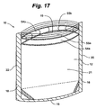
- the package 10 is depicted in an embodiment that includes a pair of fluid-filled chambers 54a, 54b proximate the opening 19.
- the fluid-filled chambers 54a, 54b and the opening 19 may extend essentially the width of the package 10 or opening 19.
- the fluid-filled chambers 54a, 54b are located on opposite front and back panels 12 and 14, respectively, at substantially the same elevation.
- Interlocking members 55a and 55b are disposed on the front and back panels 12 and 14, respectively, just above the fluid filled chambers 54a and 54b.
- the interlocking members 55a and 55b may be a zipper closure, such as disclosed in U.S. Patent No. 6,376,035 to Dobreski et al.
- the fluid-filled chambers 54a and 54b may be constructed of a suitable thin-walled elastic film known for retention or low permeability of gas, such as a polyethylene, a polyethylene/ethylene vinyl alcohol copolymer or other suitable polymers.
- the package is closed by joining interlocking members 55a and 55b, which also causes chambers 54a and 54b to contact each other and form an interface area 56 that extends the width of the package 10 or opening 19.
- the holding force of the interlocking members 55a and 55b causes a pressure at the interface area 56 to positively seal the inner cavity 21.
- the package 10 is sealed not only by the closure of the interlocking members 55a and 55b, but additionally by the contact between the fluid-filled chambers 54a and 54b which may enhance the integrity of the closure.
- the package 10 is depicted in another embodiment.
- This embodiment can have all of the same components and operational aspects as the embodiment of Figs. 17-20 , but differs in the orientation of the interlocking members 55a and 55b relative to the fluid-filled chambers 54a and 54b.
- the interlocking members 55a and 55b are located on the interior side of the interface area 56. Accordingly, the interlocking members 55a and 55b may form the primary seal, with the interface area 56 constituting a backup or secondary seal.
- FIG. 24 and 25 another embodiment of the package 10 with contacting fluid-filled chambers is depicted.
- the interlocking member 55a is disposed on an interior portion of front panel 12 between two distinct fluid-filled chambers 54a and 57a
- interlocking member 55b is disposed on an interior portion of the back panel 14 between two distinct fluid-filled chambers 54b and 57b.
- the coupling of the interlocking members 55a and 55b holds the two pairs of chambers 54a, 54b and 57a, 57b in contact to form two interface areas 56. In this way, the sealing area may be doubled or otherwise increased.
- the package 10 is depicted using a tin-tie closure to hold chambers 54a and 54b in contact in an embodiment.
- the tin-tie closure can be of any such device known to a skilled artisan.
- a pair of flap portions 58a and 58b extend upward from the front and back panels 12 and 14, respectively and above the fluid-filled chambers 54a and 54b.
- a tin-tie 58c having ends that extend beyond the width of the package 10 in both directions may be disposed on an outer surface of the front panel 12 adjacent the chamber 54a.
- the package 10 is closed by pressing the flap portions 58a and 58b together and folding them downward to form a crease or bend 58d that runs the width of the package 10.
- the flap portions 58a and 58b are held in the creased positions by folding the ends of the tin-tie 58c over the folded flap portions 58a and 58b or over or around the package.
- the chambers 54a and 54b may be held in contact by the crease 58d and retention applied by the force of the tin-tie.
- the interlocking members 55a and 55b need not provide sealing for the package 10. Rather, the integrity of the seal can be maintained by the various fluid-filled chambers 54a, 54b and/or 57a, 57b.
- the interlocking members 55a and 55b need only function to hold the fluid-filled chambers 54a, 54b and/or 57a, 57b in contact. Accordingly, the package 10 may continue to function properly even if the interlocking members 55a, 55b become damaged or become plastically deformed from repeated operation.
- a package 10 including fluid-filled chambers 59a and 59b that interlock is depicted in an embodiment of the invention.
- a plurality of distinct fluid-filled chambers 59a are formed on the front panel 12 and a plurality of distinct fluid-filled chambers 59b are formed on the back panel 14.
- the fluid-filled chambers 59a, 59b are shaped and positioned so that when the opening 19 is closed, the fluid-filled chambers 59a, 59b interlock.
- These chambers 59a, 59b can be taut or substantially filled with fluid to provide a semi-rigid or firm structure for interlocking.
- At least one of the chambers 59a, 59b may be replaced with a solid member (not depicted) shaped to engage with the opposing fluid-filled chamber and effect a seal.
- the solid member may be of a rigid or a flexible material.
- the interlocking of the fluid-filled chambers 59a, 59b serves to hold the fluid-filled chambers 59a, 59b in contact and thereby seal the package 10.
- no additional structure is required to hold the fluid-filled chambers 59a, 59b in contact and maintain the seal.
- closure structures as described herein could be implemented to further secure the contents of the package 10.
- fastening means may be situated both above and below the fluid-filled chambers 59a, 59b to provide additional security while maintaining a symmetrical force on the interlocking fluid-filled chambers 59a, 59b (not depicted).
- Figs. 30 and 31 portrays two fluid-filled chambers on each of the opposing panels.
- the interlocking function may instead be affected by two fluid filled chambers on one panel (e.g. two fluid-filled chambers 59a) and one on the opposite panel that slips therebetween (e.g. only the lower fluid-filled chamber 59b).
- the interlocking function may be affected by more than two fluid-filled chambers on each panel.
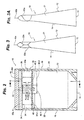
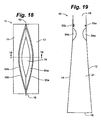
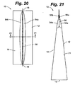
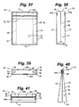
- the package 10 having a funnel or necking portion 60 is depicted in an embodiment.
- the necking portion 60 is defined by longitudinal edges 20, 22 and edge seals 16, 18 that converge to define a throat portion 62.
- the throat portion 62 includes the fluid-filled chambers 54a and 54b to form the interface area 56 therebetween.
- the fluid-filled chambers 54a and 54b may be integrally formed with and held in sealing contact by the throat portion 62.
- a top seal 64 may be integrally formed with side seals 16 and 18 to initially seal the package 10.
- the top seal 64 ( Fig. 33 ) may be removed by tearing or cutting.
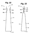
- a conduit 65 such as a straw or tube may be inserted between the fluid-filled chambers 54a and 54b ( Fig. 33b ).
- the interface area 56 of the package 10 can serve to regulate or control the flow or exit of the contents from the package 10. Control of the flow may be accomplished by squeezing a portion of the package to force the contents (e.g. a fluid) through the interface area 56.
- the conduit 65 passing through the interface area 56 can further facilitate this regulation or access.
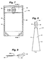
- the throat portion 62 may be formed from two halves 62a and 62b that define recesses 66a and 66b, respectively.
- the fluid-filled chambers 54a and 54b are operatively coupled with the respective halves 62a and 62b of the throat portion 62.
- the fluid-filled chambers 54a and 54b may be sized to protrude away from the respective recesses 66a and 66b at a distance D ( Fig. 35a ).
- the fluid-filled chambers 54a and 54b are compressed into the recesses 66a and 66b of halves 62a and 62b ( Fig. 35b ).
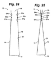
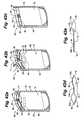
- Figs. 36, 36a and 36b only the single fluid-filled chamber 54a is utilized in the throat portion 62 to effect the sealing interface 56 in an embodiment of the invention.
- the throat portion 62 and the single fluid-filled chamber 54a cooperate to form the interface area 56 therebetween, as shown in Fig. 36 .
- the throat portion 62 may generally comply with the contour of the fluid-filled chamber 54a, thus mitigating against the formation of creases that may cause a leak path through the sealing interface 56.
- a protective film or flap 66.1 may be included that shrouds at least a portion of an exterior surface of the single fluid-filled chamber 54a and extends interstitially between the fluid-filled chamber 54a and the throat portion 62.
- Such a configuration would include two sealing surfaces 56-one between the flap 66.1 and the fluid-filled chamber 54a, the other between the flap 66.1 and the throat 62.
- a throat-shaped portion is not required and the interface area 56 can be configured for any known package 10 design to provide regulation of contents out of, or access into the package through the opening, whether by two opposing fluid chambers or by a single fluid chamber in cooperation with an opposing member.
- the top seal 64 may provide a secure seal that ensures the retention of the contents and the integrity of package 10 during shipping and handling.
- the contents of package 10 may be extracted by tearing off or cutting off the top seal 64 ( Fig. 35 ) and causing an internal pressure that separates the members defining the interface area 56 for selective breaching thereof, enabling the contents of the package 10 to flow therethrough.
- the contents may also be removed through the conduit 65, for example by applying a suction force on the conduit 65 or by applying pressure to the package 10 that forces the contents through the conduit 65.
- the flap 66.1 may serve to protect the fluid-filled chamber 54a against puncture when inserting the conduit 65 or against other elements that may puncture the fluid-filled chamber 54a.
- the contact pressure of the interface area 56 may be tailored during the formation of the throat portion 62 and fluid-filled chambers 54a and 54b so that the internal pressure required to separate the fluid-filled chambers 54a and 54b meets a specified criterion.
- the pressure at the interface area 56 as formed above is a function of several parameters, including the pressure and compressibility of the fluid within the fluid-filled chamber(s) 54a, 54b, the dimension D of the protrusion away from the recesses, and the thickness and stiffness (modulus of elasticity) of the materials that comprise the throat portion 62 and the fluid-filled chamber(s) 54a, 54b.
- the fluid-filled chamber(s) 54a, 54b may be filled with a compressible gas such as air and have a wall thickness from 0.0508 mm to 0.1016 mm (0.002- to 0.004- inches).
- a non-limiting and representative dimension D is on the order of 6.35 mm (0.25-in). Higher internal pressures and greater protrusions D may tend to increase the pressure of the interface area 56, as may greater thickness and stiffness of the throat portion 62 and the fluid-filled chambers 54a and 54b.
- the contact pressure may be tailored to enable flow of the contents due merely to the initial hydrostatic forces caused when the package 10 is tipped on end (i.e. with the throat portion 62 positioned below the contents of the package 10).
- the contact pressure may be increased so that the interface area 56 is maintained regardless of the orientation of the package, thus requiring an additional pressure be applied to the inner cavity 21 for the contents to flow out, such as by squeezing or shaking the package 10.
- the fluid-filled chamber(s) 54a and/or 54b may also be tailored to substantially provide a seal 67 between the inner cavity 21 and the exterior surface of the conduit 65.
- the conduit may be used to inject or extract the contents of the package 10.
- the seal 67 may limit leaking or spilling of the contents of package 10 through the throat portion 62, even when the conduit 65 is in place, for example in where the user is engaged in a rigorous activity (e.g. walking, biking or jogging) or in situations where the user is unskillful (e.g. a toddler, handicapped or aged person).
- the seal 67 may also limit exposure of the contents of the inner cavity 21 to the ambient atmosphere compared to a configuration where the throat is simply open to atmosphere.
- the fluid-filled chambers 54a and 54b may also provide automatic sealing of the package 10 upon removal of the conduit 65, thereby limiting contamination and spilling of the contents of package 10 when the conduit 65 is not in place.
- each of the gusseted sides 70 are characterized by a crease 76 that extends between the fluid-filled chambers 54a and 54b to proximate the top end 74 of the package 10.
- a clip 78 can be placed over the top end 74 of the closed package 10 to maintain the fluid-filled chambers 54a and 54b in the closed position.
- Other fastening means may be utilized, such as tape, tin ties or the like.
- the gusseted sides 70 may be in an extended or semi-extended position that enables the fluid-filled chambers 54a and 54b to remain substantially parallel to each other in the open position.
- the closed position Figs. 40 and 41
- the gusseted sides 70 are in a folded position with the creases 76 pinched between the fluid-filled chambers 54a and 54b.
- the package 10 is sealed near the ends of the fluid-filled chambers 54a and 54b by registering against the folded gusseted sides 70 pinched therebetween.
- the gusseted sides 70 provide a greater access opening to the internal cavity 21, enabling larger objects to be placed therein with greater ease, and full expansion of the package provided by the gussets.
- the interface area 56 when formed between the fluid-filled chambers 54a and 54b and between the fluid filled chambers 54a, 54b and the gusseted sides 70 in the pinched position, may isolate the cavity 21 from ambient atmosphere and prevent accidental spilling of the contents of the package 10.
- any of the fluid-filled chambers described herein can be constructed of multiple smaller pockets to define the larger chamber.
- the fluid chambers can be separately applied to the package panels or integrally formed with the package (e.g., by folding a top or edge portion of the package onto itself), and could run the machine direction of the pouch or at other angles or directions. Additionally, the chambers and other devices could be applied during package formation or at any other time after the package is formed. Moreover, the fluid chambers may be applied to flexible, semi-rigid, or rigid packages, or a combination of such materials, to provide the sealing and closure structures and functions disclosed herein.
- a user filled flexible package 90 having an opening 92 in combination with the fluid actuated closure 30 is depicted in an embodiment of the invention.
- the user filled flexible package 90 may include at least one fluid actuated closure 30 attached to the front or back panel 12 or 14 of the flexible package 90.
- the user filled flexible package 90 includes a two-sided tape 94, one side of which being adhered to the interior of the flexible package (e.g. to the font panel 12) and the other side being shielded by a release liner 96.
- the two-sided tape 94 may be adhered to a portion of the front panel 12 opposite the fluid actuated closure 30 as depicted.
- the two-sided tape may span the area of the fluid actuated closure 30 that includes the reservoir portion 34 and the restriction channel 44 or fluid regulator 40.
- Other known closure techniques and methods can be used instead of the tape 94.
- the end user can open the entire or a substantial portion of the length of the opening 92 for placement of articles in the flexible package 90.
- the end user can peal the release liner 96 off of the two-sided tape 94 and press the front and back panels 12 and 14 together causing the exposed inward face of the two-sided tape 94 to adhere to the reservoir portion 34 and the portion housing the restriction channel 44 or fluid regulator 40 of the fluid actuated closure 30.
- the two-sided tape 94 provides a seal between the front panel 12 and the reservoir portion 34 / fluid regulator 44 portion.
- the fluid chamber 33b of the closure portion 36 may cooperate with the front panel 12 to provide a selective seal.
- the user can apply pressure to transfer the fluid between the reservoir portion 34 and the closure portion 36 to provide selective access into the cavity or to regulate material exiting or entering the package 10 through the access opening 92.
- the fluid may reside in the closure portion 36 only, confronting the opposing package side such as described attendant to Figs. 32-36 .
- the package 10 can be squeezed such that the contents of the package 10, e.g., fluid, is controllably released or forced out of the package 10, thus selectively breaching the interface area 56.
- two opposing fluid filled chambers 54a, 54b can be configured with the opening 92 as well.
- the two-sided tape 94 may include an aggressive adhesive that renders an essentially permanent seal between the two-sided tape 94 and the sealed portion of the fluid actuated closure 30.
- the adhesive may be less aggressive, enabling the user to re-open the opening 92 and refill the flexible package therethrough several times.
- Sealing means other than the two-sided tape 94 can also be used with the user filled flexible package 90, such as zippers, pinch locks, hook and loop materials (e.g. VELCRO) and other sealing means available to the artisan. Whatever sealing means is used could be applied during the manufacturing of the package, or as a side operation before being placed on the market. It may even be sold as a kit, compete with instructions provided on a tangible medium for the consumer to apply the sealing means to the package themselves.
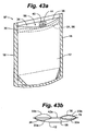
- a flexible package 97 having an auxiliary access 98 is depicted in an embodiment.
- This embodiment is contrasted from the embodiment of Figs. 42A-42E in that includes the dual fluid-filled chambers 33a and 33b and the auxiliary access 98 is distinct from the access opening 92. Accordingly, the two-sided tape 94 transverses substantially the length of the auxiliary access 98 for sealing the auxiliary access 98.
- Fig. 43A depicts the two-sided tape 94 for sealing
- a variety of sealing means could be utilized, including but not limited to an adhesive, zippers, pinch locks, hook and loop materials.
- the user filled flexible packages 90, 97 can be sold to the consumer empty.
- the consumer could, as with user filled packages (e.g. ZIP-LOC packages), purchase a number of the flexible packages 90 to store whatever products or articles they wish.
- user filled packages e.g. ZIP-LOC packages
- a metered flexible package 100 including a main compartment 102 and a metered compartment 104 connected by a passageway 105 is depicted in an embodiment of the invention.
- the boundary between the main compartment 102 and the metered compartment 104 may be defined by one of the various fluid-filled chamber devices herein described, such as the single fluid filled chamber 54a disposed in the passageway 105 that cooperates with an opposing member 106 to define the interface area 56 (depicted) for sealing in the passageway 105.
- the metered flexible package 100 may include a handle portion 108.
- the metered compartment 104 is so named because it may be sized to contain a quantity of product to within a known or acceptable uncertainty.
- the main compartment 102 may neck down to a throat portion 110 at the passageway 105.
- a selectively sealable closure 114 such as a pinch-lock seal (depicted) may be located at a distal end portion 116 of the metered chamber 104.
- the metered chamber 104 may also include vents 118 such as slots or perforations that enable air to pass between the metered chamber 104 and the ambient surroundings.
- the user orients the metered flexible package 100 containing a product 120 so that the metered chamber 104 is below the main chamber 102 ( FIG. 44C ).
- the user can shake the metered package 100, depicted by the up/down arrow 122.
- the shaking technique may be particularly effective for pellet-type products such as dry dog food.
- the down motions of the shaking motion 122 may cause a portion of the product 120 to breach the interface area 56 from the main chamber 102 into the metered chamber 104.
- the vents 118 when present, enable air that is displaced by the product 120 entering the metered chamber 104 to be pushed out of the metered chamber 104 while still containing the product 120. This process may continue until the metered chamber 104 is filled.
- the metered chamber 104 is filled, the quantity of product 120 within the metered chamber is known to within an acceptable uncertainty.
- the user may then open the selectively sealable closure 114 to pour out the product 120 in the metered chamber 104.
- Passage of product between the chambers 102, 104 of the metered flexible package 100 fluids may also be accomplished by squeezing one of the chambers 102, 104 so as to transfer product in to the metered chamber 104. Such and approach would be particularly suitable where the squeezed chamber contains a liquid.
- the concept of the metered flexible package 100 may be extended to include mixing of products located in adjacent chambers and separated by the fluid chamber closure (e.g. mixing two liquids or mixing a liquid with a granular product).
Landscapes
- Engineering & Computer Science (AREA)
- Mechanical Engineering (AREA)
- Bag Frames (AREA)
- Packages (AREA)
Applications Claiming Priority (5)
| Application Number | Priority Date | Filing Date | Title |
|---|---|---|---|
| US91644207P | 2007-05-07 | 2007-05-07 | |
| US91707807P | 2007-05-10 | 2007-05-10 | |
| US95231107P | 2007-07-27 | 2007-07-27 | |
| US98758807P | 2007-11-13 | 2007-11-13 | |
| PCT/US2008/062918 WO2008137937A1 (en) | 2007-05-07 | 2008-05-07 | Packages having fluid-filled chamber closures |
Publications (3)
| Publication Number | Publication Date |
|---|---|
| EP2152597A1 EP2152597A1 (en) | 2010-02-17 |
| EP2152597A4 EP2152597A4 (en) | 2011-06-22 |
| EP2152597B1 true EP2152597B1 (en) | 2016-07-13 |
Family
ID=39944018
Family Applications (1)
| Application Number | Title | Priority Date | Filing Date |
|---|---|---|---|
| EP08747792.3A Active EP2152597B1 (en) | 2007-05-07 | 2008-05-07 | Packages having fluid-filled chamber closures |
Country Status (6)
| Country | Link |
|---|---|
| EP (1) | EP2152597B1 (zh) |
| JP (1) | JP5894362B2 (zh) |
| CN (1) | CN101730648B (zh) |
| CA (1) | CA2693764C (zh) |
| MX (1) | MX2009012024A (zh) |
| WO (1) | WO2008137937A1 (zh) |
Families Citing this family (6)
| Publication number | Priority date | Publication date | Assignee | Title |
|---|---|---|---|---|
| US8613547B2 (en) | 2004-11-05 | 2013-12-24 | Mark Steele | Packages having bubble-shaped closures |
| BRPI0517681B1 (pt) | 2004-11-05 | 2021-10-13 | Mark Steele | Embalagens para conter um material |
| MX2017012879A (es) | 2015-04-09 | 2018-08-01 | Steele Mark | Sistema y metodo de cierre de valvula de envase. |
| GB201610432D0 (en) * | 2016-06-15 | 2016-07-27 | Mars Inc | Easy Peel Pouch |
| WO2019187723A1 (ja) * | 2018-03-28 | 2019-10-03 | 凸版印刷株式会社 | 包装体 |
| CN109808237A (zh) * | 2019-03-22 | 2019-05-28 | 中山市新宏业自动化工业有限公司 | 一种软包装袋在线加导流条装置 |
Citations (1)
| Publication number | Priority date | Publication date | Assignee | Title |
|---|---|---|---|---|
| US3224640A (en) * | 1962-06-21 | 1965-12-21 | Wayne Rodgers V | Reclosable package |
Family Cites Families (10)
| Publication number | Priority date | Publication date | Assignee | Title |
|---|---|---|---|---|
| NL8502366A (nl) * | 1985-08-28 | 1987-03-16 | Leer Koninklijke Emballage | Verpakking voor drank en werkwijze voor het vervaardigen van de verpakking. |
| US4923701A (en) * | 1989-01-12 | 1990-05-08 | Minigrip, Inc. | Zippered cook-in-bag pouch and method |
| US5919535A (en) * | 1996-12-05 | 1999-07-06 | Tenneco Packaging | Fins for plastic bags |
| US6149304A (en) * | 1997-05-09 | 2000-11-21 | The Procter & Gamble Company | Flexible storage bag with selectively-activatible closure |
| TW534891B (en) * | 1999-02-17 | 2003-06-01 | Tetra Laval Holdings & Finance | Packing container and method of manufacturing the container |
| US6020013A (en) * | 1999-03-01 | 2000-02-01 | Kozma; Saul A. | Method of preventing freezer burn on food in storage bags |
| US7048442B2 (en) * | 2002-05-15 | 2006-05-23 | Illinois Tool Works Inc. | Reclosable packaging for scoopable products and method of manufacture |
| US20050139603A1 (en) * | 2003-01-08 | 2005-06-30 | Han-Pin Lee | Intra-packaging straw for laminated paperboard-based liquid containers |
| JP2005022760A (ja) * | 2003-06-10 | 2005-01-27 | Maintech Kanzai:Kk | 切り花輸送用容器及び輸送用切り花の支持方法 |
| BRPI0517681B1 (pt) * | 2004-11-05 | 2021-10-13 | Mark Steele | Embalagens para conter um material |
-
2008
- 2008-05-07 CN CN200880023730.6A patent/CN101730648B/zh active Active
- 2008-05-07 EP EP08747792.3A patent/EP2152597B1/en active Active
- 2008-05-07 CA CA2693764A patent/CA2693764C/en active Active
- 2008-05-07 JP JP2010507623A patent/JP5894362B2/ja active Active
- 2008-05-07 MX MX2009012024A patent/MX2009012024A/es active IP Right Grant
- 2008-05-07 WO PCT/US2008/062918 patent/WO2008137937A1/en active Application Filing
Patent Citations (1)
| Publication number | Priority date | Publication date | Assignee | Title |
|---|---|---|---|---|
| US3224640A (en) * | 1962-06-21 | 1965-12-21 | Wayne Rodgers V | Reclosable package |
Also Published As
| Publication number | Publication date |
|---|---|
| JP5894362B2 (ja) | 2016-03-30 |
| CN101730648B (zh) | 2013-05-01 |
| MX2009012024A (es) | 2010-01-25 |
| JP2010526736A (ja) | 2010-08-05 |
| EP2152597A4 (en) | 2011-06-22 |
| CN101730648A (zh) | 2010-06-09 |
| EP2152597A1 (en) | 2010-02-17 |
| WO2008137937A1 (en) | 2008-11-13 |
| CA2693764C (en) | 2016-01-19 |
| CA2693764A1 (en) | 2008-11-13 |
Similar Documents
| Publication | Publication Date | Title |
|---|---|---|
| US10479041B2 (en) | Stationary closure device and package | |
| US8613547B2 (en) | Packages having bubble-shaped closures | |
| US7207717B2 (en) | Package having a fluid actuated closure | |
| US7946766B2 (en) | Offset closure mechanism for a reclosable pouch | |
| AU2021201252B2 (en) | Package valve closure system and method | |
| US10329053B2 (en) | Package having a fill and seal feature | |
| US8529129B2 (en) | Closure element for a pouch | |
| US20070110340A1 (en) | Tamper evident polymeric package with zipper closure and valve, and methods | |
| US20080310774A1 (en) | Pouch with a valve | |
| EP2152597B1 (en) | Packages having fluid-filled chamber closures | |
| US20070110343A1 (en) | Ventable package with zipper closure, and methods | |
| US20070263948A1 (en) | Ventable Package with Zipper Closure, and Methods | |
| US20200255202A1 (en) | Package having a spout reservoir/retaining feature | |
| EP3841032B1 (en) | Fold and seal flexible valves | |
| US20080124007A1 (en) | Package with strip-based closure system and method for its manufacture | |
| US20080304771A1 (en) | Vacuum storage bag with zipper |
Legal Events
| Date | Code | Title | Description |
|---|---|---|---|
| PUAI | Public reference made under article 153(3) epc to a published international application that has entered the european phase |
Free format text: ORIGINAL CODE: 0009012 |
|
| 17P | Request for examination filed |
Effective date: 20091203 |
|
| AK | Designated contracting states |
Kind code of ref document: A1 Designated state(s): AT BE BG CH CY CZ DE DK EE ES FI FR GB GR HR HU IE IS IT LI LT LU LV MC MT NL NO PL PT RO SE SI SK TR |
|
| AX | Request for extension of the european patent |
Extension state: AL BA MK RS |
|
| DAX | Request for extension of the european patent (deleted) | ||
| A4 | Supplementary search report drawn up and despatched |
Effective date: 20110524 |
|
| RIC1 | Information provided on ipc code assigned before grant |
Ipc: B65D 33/38 20060101ALI20110518BHEP Ipc: B65D 75/58 20060101ALI20110518BHEP Ipc: B65D 77/28 20060101ALI20110518BHEP Ipc: B65D 33/20 20060101ALI20110518BHEP Ipc: B65D 33/16 20060101AFI20081126BHEP |
|
| 17Q | First examination report despatched |
Effective date: 20120416 |
|
| GRAP | Despatch of communication of intention to grant a patent |
Free format text: ORIGINAL CODE: EPIDOSNIGR1 |
|
| INTG | Intention to grant announced |
Effective date: 20160211 |
|
| GRAP | Despatch of communication of intention to grant a patent |
Free format text: ORIGINAL CODE: EPIDOSNIGR1 |
|
| INTG | Intention to grant announced |
Effective date: 20160314 |
|
| GRAS | Grant fee paid |
Free format text: ORIGINAL CODE: EPIDOSNIGR3 |
|
| GRAA | (expected) grant |
Free format text: ORIGINAL CODE: 0009210 |
|
| AK | Designated contracting states |
Kind code of ref document: B1 Designated state(s): AT BE BG CH CY CZ DE DK EE ES FI FR GB GR HR HU IE IS IT LI LT LU LV MC MT NL NO PL PT RO SE SI SK TR |
|
| REG | Reference to a national code |
Ref country code: GB Ref legal event code: FG4D |
|
| REG | Reference to a national code |
Ref country code: AT Ref legal event code: REF Ref document number: 812086 Country of ref document: AT Kind code of ref document: T Effective date: 20160715 Ref country code: CH Ref legal event code: EP |
|
| REG | Reference to a national code |
Ref country code: IE Ref legal event code: FG4D |
|
| REG | Reference to a national code |
Ref country code: DE Ref legal event code: R096 Ref document number: 602008045088 Country of ref document: DE |
|
| REG | Reference to a national code |
Ref country code: LT Ref legal event code: MG4D |
|
| REG | Reference to a national code |
Ref country code: NL Ref legal event code: MP Effective date: 20160713 |
|
| REG | Reference to a national code |
Ref country code: AT Ref legal event code: MK05 Ref document number: 812086 Country of ref document: AT Kind code of ref document: T Effective date: 20160713 |
|
| PG25 | Lapsed in a contracting state [announced via postgrant information from national office to epo] |
Ref country code: FI Free format text: LAPSE BECAUSE OF FAILURE TO SUBMIT A TRANSLATION OF THE DESCRIPTION OR TO PAY THE FEE WITHIN THE PRESCRIBED TIME-LIMIT Effective date: 20160713 Ref country code: NL Free format text: LAPSE BECAUSE OF FAILURE TO SUBMIT A TRANSLATION OF THE DESCRIPTION OR TO PAY THE FEE WITHIN THE PRESCRIBED TIME-LIMIT Effective date: 20160713 Ref country code: HR Free format text: LAPSE BECAUSE OF FAILURE TO SUBMIT A TRANSLATION OF THE DESCRIPTION OR TO PAY THE FEE WITHIN THE PRESCRIBED TIME-LIMIT Effective date: 20160713 Ref country code: NO Free format text: LAPSE BECAUSE OF FAILURE TO SUBMIT A TRANSLATION OF THE DESCRIPTION OR TO PAY THE FEE WITHIN THE PRESCRIBED TIME-LIMIT Effective date: 20161013 Ref country code: IT Free format text: LAPSE BECAUSE OF FAILURE TO SUBMIT A TRANSLATION OF THE DESCRIPTION OR TO PAY THE FEE WITHIN THE PRESCRIBED TIME-LIMIT Effective date: 20160713 Ref country code: LT Free format text: LAPSE BECAUSE OF FAILURE TO SUBMIT A TRANSLATION OF THE DESCRIPTION OR TO PAY THE FEE WITHIN THE PRESCRIBED TIME-LIMIT Effective date: 20160713 Ref country code: IS Free format text: LAPSE BECAUSE OF FAILURE TO SUBMIT A TRANSLATION OF THE DESCRIPTION OR TO PAY THE FEE WITHIN THE PRESCRIBED TIME-LIMIT Effective date: 20161113 |
|
| PG25 | Lapsed in a contracting state [announced via postgrant information from national office to epo] |
Ref country code: AT Free format text: LAPSE BECAUSE OF FAILURE TO SUBMIT A TRANSLATION OF THE DESCRIPTION OR TO PAY THE FEE WITHIN THE PRESCRIBED TIME-LIMIT Effective date: 20160713 Ref country code: ES Free format text: LAPSE BECAUSE OF FAILURE TO SUBMIT A TRANSLATION OF THE DESCRIPTION OR TO PAY THE FEE WITHIN THE PRESCRIBED TIME-LIMIT Effective date: 20160713 Ref country code: PL Free format text: LAPSE BECAUSE OF FAILURE TO SUBMIT A TRANSLATION OF THE DESCRIPTION OR TO PAY THE FEE WITHIN THE PRESCRIBED TIME-LIMIT Effective date: 20160713 Ref country code: SE Free format text: LAPSE BECAUSE OF FAILURE TO SUBMIT A TRANSLATION OF THE DESCRIPTION OR TO PAY THE FEE WITHIN THE PRESCRIBED TIME-LIMIT Effective date: 20160713 Ref country code: GR Free format text: LAPSE BECAUSE OF FAILURE TO SUBMIT A TRANSLATION OF THE DESCRIPTION OR TO PAY THE FEE WITHIN THE PRESCRIBED TIME-LIMIT Effective date: 20161014 Ref country code: BE Free format text: LAPSE BECAUSE OF FAILURE TO SUBMIT A TRANSLATION OF THE DESCRIPTION OR TO PAY THE FEE WITHIN THE PRESCRIBED TIME-LIMIT Effective date: 20160713 Ref country code: PT Free format text: LAPSE BECAUSE OF FAILURE TO SUBMIT A TRANSLATION OF THE DESCRIPTION OR TO PAY THE FEE WITHIN THE PRESCRIBED TIME-LIMIT Effective date: 20161114 Ref country code: LV Free format text: LAPSE BECAUSE OF FAILURE TO SUBMIT A TRANSLATION OF THE DESCRIPTION OR TO PAY THE FEE WITHIN THE PRESCRIBED TIME-LIMIT Effective date: 20160713 |
|
| REG | Reference to a national code |
Ref country code: DE Ref legal event code: R097 Ref document number: 602008045088 Country of ref document: DE |
|
| PG25 | Lapsed in a contracting state [announced via postgrant information from national office to epo] |
Ref country code: EE Free format text: LAPSE BECAUSE OF FAILURE TO SUBMIT A TRANSLATION OF THE DESCRIPTION OR TO PAY THE FEE WITHIN THE PRESCRIBED TIME-LIMIT Effective date: 20160713 Ref country code: RO Free format text: LAPSE BECAUSE OF FAILURE TO SUBMIT A TRANSLATION OF THE DESCRIPTION OR TO PAY THE FEE WITHIN THE PRESCRIBED TIME-LIMIT Effective date: 20160713 |
|
| PLBE | No opposition filed within time limit |
Free format text: ORIGINAL CODE: 0009261 |
|
| STAA | Information on the status of an ep patent application or granted ep patent |
Free format text: STATUS: NO OPPOSITION FILED WITHIN TIME LIMIT |
|
| REG | Reference to a national code |
Ref country code: FR Ref legal event code: PLFP Year of fee payment: 10 |
|
| PG25 | Lapsed in a contracting state [announced via postgrant information from national office to epo] |
Ref country code: BG Free format text: LAPSE BECAUSE OF FAILURE TO SUBMIT A TRANSLATION OF THE DESCRIPTION OR TO PAY THE FEE WITHIN THE PRESCRIBED TIME-LIMIT Effective date: 20161013 Ref country code: CZ Free format text: LAPSE BECAUSE OF FAILURE TO SUBMIT A TRANSLATION OF THE DESCRIPTION OR TO PAY THE FEE WITHIN THE PRESCRIBED TIME-LIMIT Effective date: 20160713 Ref country code: DK Free format text: LAPSE BECAUSE OF FAILURE TO SUBMIT A TRANSLATION OF THE DESCRIPTION OR TO PAY THE FEE WITHIN THE PRESCRIBED TIME-LIMIT Effective date: 20160713 Ref country code: SK Free format text: LAPSE BECAUSE OF FAILURE TO SUBMIT A TRANSLATION OF THE DESCRIPTION OR TO PAY THE FEE WITHIN THE PRESCRIBED TIME-LIMIT Effective date: 20160713 |
|
| 26N | No opposition filed |
Effective date: 20170418 |
|
| PG25 | Lapsed in a contracting state [announced via postgrant information from national office to epo] |
Ref country code: SI Free format text: LAPSE BECAUSE OF FAILURE TO SUBMIT A TRANSLATION OF THE DESCRIPTION OR TO PAY THE FEE WITHIN THE PRESCRIBED TIME-LIMIT Effective date: 20160713 Ref country code: LU Free format text: LAPSE BECAUSE OF NON-PAYMENT OF DUE FEES Effective date: 20170531 |
|
| REG | Reference to a national code |
Ref country code: CH Ref legal event code: PL |
|
| PG25 | Lapsed in a contracting state [announced via postgrant information from national office to epo] |
Ref country code: MC Free format text: LAPSE BECAUSE OF FAILURE TO SUBMIT A TRANSLATION OF THE DESCRIPTION OR TO PAY THE FEE WITHIN THE PRESCRIBED TIME-LIMIT Effective date: 20160713 |
|
| REG | Reference to a national code |
Ref country code: IE Ref legal event code: MM4A |
|
| PG25 | Lapsed in a contracting state [announced via postgrant information from national office to epo] |
Ref country code: LI Free format text: LAPSE BECAUSE OF NON-PAYMENT OF DUE FEES Effective date: 20170531 Ref country code: CH Free format text: LAPSE BECAUSE OF NON-PAYMENT OF DUE FEES Effective date: 20170531 |
|
| PG25 | Lapsed in a contracting state [announced via postgrant information from national office to epo] |
Ref country code: LU Free format text: LAPSE BECAUSE OF NON-PAYMENT OF DUE FEES Effective date: 20170507 |
|
| PG25 | Lapsed in a contracting state [announced via postgrant information from national office to epo] |
Ref country code: IE Free format text: LAPSE BECAUSE OF NON-PAYMENT OF DUE FEES Effective date: 20170507 |
|
| REG | Reference to a national code |
Ref country code: FR Ref legal event code: PLFP Year of fee payment: 11 |
|
| PG25 | Lapsed in a contracting state [announced via postgrant information from national office to epo] |
Ref country code: MT Free format text: LAPSE BECAUSE OF NON-PAYMENT OF DUE FEES Effective date: 20170507 |
|
| PG25 | Lapsed in a contracting state [announced via postgrant information from national office to epo] |
Ref country code: HU Free format text: LAPSE BECAUSE OF FAILURE TO SUBMIT A TRANSLATION OF THE DESCRIPTION OR TO PAY THE FEE WITHIN THE PRESCRIBED TIME-LIMIT; INVALID AB INITIO Effective date: 20080507 |
|
| PG25 | Lapsed in a contracting state [announced via postgrant information from national office to epo] |
Ref country code: CY Free format text: LAPSE BECAUSE OF NON-PAYMENT OF DUE FEES Effective date: 20160713 |
|
| PG25 | Lapsed in a contracting state [announced via postgrant information from national office to epo] |
Ref country code: TR Free format text: LAPSE BECAUSE OF FAILURE TO SUBMIT A TRANSLATION OF THE DESCRIPTION OR TO PAY THE FEE WITHIN THE PRESCRIBED TIME-LIMIT Effective date: 20160713 |
|
| PGFP | Annual fee paid to national office [announced via postgrant information from national office to epo] |
Ref country code: GB Payment date: 20240521 Year of fee payment: 17 |
|
| PGFP | Annual fee paid to national office [announced via postgrant information from national office to epo] |
Ref country code: DE Payment date: 20240521 Year of fee payment: 17 |
|
| PGFP | Annual fee paid to national office [announced via postgrant information from national office to epo] |
Ref country code: FR Payment date: 20240529 Year of fee payment: 17 |