EP3841032B1 - Fold and seal flexible valves - Google Patents
Fold and seal flexible valves Download PDFInfo
- Publication number
- EP3841032B1 EP3841032B1 EP19762047.9A EP19762047A EP3841032B1 EP 3841032 B1 EP3841032 B1 EP 3841032B1 EP 19762047 A EP19762047 A EP 19762047A EP 3841032 B1 EP3841032 B1 EP 3841032B1
- Authority
- EP
- European Patent Office
- Prior art keywords
- valve
- package
- hinge element
- channel
- bubble
- Prior art date
- Legal status (The legal status is an assumption and is not a legal conclusion. Google has not performed a legal analysis and makes no representation as to the accuracy of the status listed.)
- Active
Links
- 239000012530 fluid Substances 0.000 claims description 22
- 230000000712 assembly Effects 0.000 claims description 9
- 238000000429 assembly Methods 0.000 claims description 9
- 230000013011 mating Effects 0.000 claims 1
- 239000000463 material Substances 0.000 description 7
- 238000007789 sealing Methods 0.000 description 4
- 238000009459 flexible packaging Methods 0.000 description 3
- 238000004519 manufacturing process Methods 0.000 description 3
- 238000000034 method Methods 0.000 description 3
- 238000003856 thermoforming Methods 0.000 description 3
- 239000000853 adhesive Substances 0.000 description 2
- 230000001070 adhesive effect Effects 0.000 description 2
- 239000003086 colorant Substances 0.000 description 2
- 239000007788 liquid Substances 0.000 description 2
- 238000004806 packaging method and process Methods 0.000 description 2
- 230000009467 reduction Effects 0.000 description 2
- 230000007704 transition Effects 0.000 description 2
- 230000009471 action Effects 0.000 description 1
- XAGFODPZIPBFFR-UHFFFAOYSA-N aluminium Chemical compound [Al] XAGFODPZIPBFFR-UHFFFAOYSA-N 0.000 description 1
- 229910052782 aluminium Inorganic materials 0.000 description 1
- 239000004411 aluminium Substances 0.000 description 1
- 235000013361 beverage Nutrition 0.000 description 1
- 239000002131 composite material Substances 0.000 description 1
- 238000010276 construction Methods 0.000 description 1
- 239000007789 gas Substances 0.000 description 1
- 230000007246 mechanism Effects 0.000 description 1
- 238000012856 packing Methods 0.000 description 1
- 239000004033 plastic Substances 0.000 description 1
Images


Classifications
-
- B—PERFORMING OPERATIONS; TRANSPORTING
- B65—CONVEYING; PACKING; STORING; HANDLING THIN OR FILAMENTARY MATERIAL
- B65D—CONTAINERS FOR STORAGE OR TRANSPORT OF ARTICLES OR MATERIALS, e.g. BAGS, BARRELS, BOTTLES, BOXES, CANS, CARTONS, CRATES, DRUMS, JARS, TANKS, HOPPERS, FORWARDING CONTAINERS; ACCESSORIES, CLOSURES, OR FITTINGS THEREFOR; PACKAGING ELEMENTS; PACKAGES
- B65D47/00—Closures with filling and discharging, or with discharging, devices
- B65D47/04—Closures with discharging devices other than pumps
- B65D47/20—Closures with discharging devices other than pumps comprising hand-operated members for controlling discharge
- B65D47/2018—Closures with discharging devices other than pumps comprising hand-operated members for controlling discharge comprising a valve or like element which is opened or closed by deformation of the container or closure
-
- B—PERFORMING OPERATIONS; TRANSPORTING
- B65—CONVEYING; PACKING; STORING; HANDLING THIN OR FILAMENTARY MATERIAL
- B65D—CONTAINERS FOR STORAGE OR TRANSPORT OF ARTICLES OR MATERIALS, e.g. BAGS, BARRELS, BOTTLES, BOXES, CANS, CARTONS, CRATES, DRUMS, JARS, TANKS, HOPPERS, FORWARDING CONTAINERS; ACCESSORIES, CLOSURES, OR FITTINGS THEREFOR; PACKAGING ELEMENTS; PACKAGES
- B65D75/00—Packages comprising articles or materials partially or wholly enclosed in strips, sheets, blanks, tubes, or webs of flexible sheet material, e.g. in folded wrappers
- B65D75/52—Details
- B65D75/58—Opening or contents-removing devices added or incorporated during package manufacture
- B65D75/5861—Spouts
- B65D75/5872—Non-integral spouts
- B65D75/5883—Non-integral spouts connected to the package at the sealed junction of two package walls
-
- B—PERFORMING OPERATIONS; TRANSPORTING
- B65—CONVEYING; PACKING; STORING; HANDLING THIN OR FILAMENTARY MATERIAL
- B65D—CONTAINERS FOR STORAGE OR TRANSPORT OF ARTICLES OR MATERIALS, e.g. BAGS, BARRELS, BOTTLES, BOXES, CANS, CARTONS, CRATES, DRUMS, JARS, TANKS, HOPPERS, FORWARDING CONTAINERS; ACCESSORIES, CLOSURES, OR FITTINGS THEREFOR; PACKAGING ELEMENTS; PACKAGES
- B65D83/00—Containers or packages with special means for dispensing contents
- B65D83/0055—Containers or packages provided with a flexible bag or a deformable membrane or diaphragm for expelling the contents
-
- B—PERFORMING OPERATIONS; TRANSPORTING
- B65—CONVEYING; PACKING; STORING; HANDLING THIN OR FILAMENTARY MATERIAL
- B65D—CONTAINERS FOR STORAGE OR TRANSPORT OF ARTICLES OR MATERIALS, e.g. BAGS, BARRELS, BOTTLES, BOXES, CANS, CARTONS, CRATES, DRUMS, JARS, TANKS, HOPPERS, FORWARDING CONTAINERS; ACCESSORIES, CLOSURES, OR FITTINGS THEREFOR; PACKAGING ELEMENTS; PACKAGES
- B65D2575/00—Packages comprising articles or materials partially or wholly enclosed in strips, sheets, blanks, tubes or webs of flexible sheet material, e.g. in folded wrappers
- B65D2575/52—Details
- B65D2575/58—Opening or contents-removing devices added or incorporated during package manufacture
- B65D2575/586—Opening or contents-removing devices added or incorporated during package manufacture with means for reclosing
-
- F—MECHANICAL ENGINEERING; LIGHTING; HEATING; WEAPONS; BLASTING
- F16—ENGINEERING ELEMENTS AND UNITS; GENERAL MEASURES FOR PRODUCING AND MAINTAINING EFFECTIVE FUNCTIONING OF MACHINES OR INSTALLATIONS; THERMAL INSULATION IN GENERAL
- F16K—VALVES; TAPS; COCKS; ACTUATING-FLOATS; DEVICES FOR VENTING OR AERATING
- F16K1/00—Lift valves or globe valves, i.e. cut-off apparatus with closure members having at least a component of their opening and closing motion perpendicular to the closing faces
- F16K1/16—Lift valves or globe valves, i.e. cut-off apparatus with closure members having at least a component of their opening and closing motion perpendicular to the closing faces with pivoted closure-members
- F16K1/18—Lift valves or globe valves, i.e. cut-off apparatus with closure members having at least a component of their opening and closing motion perpendicular to the closing faces with pivoted closure-members with pivoted discs or flaps
- F16K1/20—Lift valves or globe valves, i.e. cut-off apparatus with closure members having at least a component of their opening and closing motion perpendicular to the closing faces with pivoted closure-members with pivoted discs or flaps with axis of rotation arranged externally of valve member
- F16K1/2042—Special features or arrangements of the sealing
- F16K1/2085—Movable sealing bodies
Definitions
- the present disclosure relates to a flexible valve, wherein the valve can be folded and sealed for containing liquids within flexible packaging in combination with a flexible to semi-rigid container.
- the valve includes a channel formed between a bubble element and a channel layer which is closed whenever the valve is folded and sealed.
- Protruding element valves or bubble valves are known in the art. They are frequently used with flexible to semi-rigid containers. While these valves have generally been satisfactory for their intended uses, further improvements are sought.
- DE202004000591U1 relates to a packing that consists of two parts of plastic, aluminium or composite material interconnected along the edges forming a holding space for the contents which can be removed through a withdrawal opening.
- the contents exit the package through a channel having a constiction, which can be considered a valve as in the preamble of appended claims 1 and 4.
- US4328912A relates to a self-contained valved package for a fluent commodity, and more particularly, a package with a depression/impression valve in the wall thereof.
- EP2612825A1 relates to a hair colorant container in the form of a flexible sachet having a laminate structure for storing a hair colorant component.
- the valve includes a base layer, with a bubble formed between the base layer and a bubble layer.
- a channel is formed between the bubble layer and a channel layer.
- a hinge element or separate interlocking assemblies are provided to allow the valve to be closed and secured in a folded configuration. That is, the folding and sealing of the valve caused the channel including the fluid outlet to be closed.
- the disclosed embodiments provide additional re-close functionality to provide added security desired by consumers in use cases where the package may leak should it be subjected to errant external pressure (such as in a purse, backpack or otherwise being transported). Consumer research has shown that there is a preference to perform a manual action to achieve a sense that the package is truly closed in those use cases. Therefore, the design of this valve includes the same structure and functionality in terms of the multi-layer film construction serving the role of flow control.
- Valve 10 in an unfolded or open configuration.
- Valve 10 includes a bubble valve subcomponent or protruding or bubble element 12 (with fluid outlet 13).
- the protruding or bubble element 12 is typically composed of a gas, liquid or fluid captured between a base layer 14 and a bubble layer 24 of flexible material.
- a hinge element 16 is attached to the base layer 14 opposite from the protruding or bubble element 12.
- the hinge element 16 is, for example, but not limited to, a press-to-close zipper or a self-mating zipper, typically with outwardly extending interlocking elements, and is attached to the base layer 14 (and bubble valve subcomponent or protruding or bubble element 12) either by adhesive or via traditional film sealing methods.
- the design of this hinge element 16 could likewise be an adhesive element or a form of hook-and-loop closure.
- the valve 10 is intended to be used in a package or container 100 with the storage volume 80 defined between a first panel 40 and a second panel 60 of polymeric or similar materials. Other materials or features of packages, container or pouches, such as, but not limited to, a bottom panel or a gusset, can be part of the package 100.
- the valve 10 is sealed into the package 100 between the first panel 40 and the second panel 60.
- the base layer 14 is sealed to the first panel 40 and the channel layer is sealed to the second panel 60. Also see Figures 12 and 13 .
- the bubble valve subcomponent 12 includes the base layer 14, the bubble layer 24, and the channel layer 34 defining the fluid flow channel 17 between the bubble layer 24 and the channel layer 34.
- the bubble valve subcomponent 12 and its manufacture is described in PCT/US2017/61500 entitled “Bubble Valve for Flexible Packaging,” filed on November 14, 2017 .
- the hinge element 16 provides a secondary closure measure for the valve 10. In normal operation, contents of the storage volume 80 only pass through the channel 17 and fluid outlet or exit 13 when a user applies pressure to the storage volume 80. However, in some instances, an additional or secondary closure is useful, such as when leaving the package 100 in a purse or another container where contents of the package 100 could make a mess if leaked.
- the hinge element 16 provides such a more secure secondary closure when it is in the folded or closed configuration, as illustrated in Figures 2 and 5 .
- a fold 20 develops in at least the layers 14, 24, 34 and further restricts channel 17 so no contents may pass through the valve 10, even if moderate pressure is applied to the storage volume 80.
- the hinge element 16 includes a mid-point or central area of reduced thickness 18.
- the reduced thickness 18 allows folding along a defined hinge line and further reduces obstruction or bulging when the hinge element is folded, as illustrated in Figs. 2 and 5 .
- the hinge element 16 further includes at least one ramped area 19 (e.g., one on each side of the central area of reduced thickness 18) to further facilitate closure of the hinge element 16.
- the fold of layers 14, 24, 34 in the closed configuration typically develops at the central area of reduced thickness 18, which acts as a hinge point. The entire valve 10 can be folded back upon itself and snapped into a fixed position with the channel 17 now kinked and the flow more reliably cutoff or terminated.
- the end of the valve 10 can be pulled, the hinge element 16 releases and returns to the unfolded or open configuration illustrated in Figures 1 and 4 .
- the user can again squeeze the pouch 80 as before to dispense products from the storage volume 80 in the pouch through the channel 17 and fluid outlet or exit 13.
- FIG. 1 through 5 show hinge element 16 parallel and aligned with the center of the protruding element 12, other alignments are possible.
- Figure 6 illustrates an open configuration of valve 10' with hinge elements 16'a and 16'b that are perpendicular to the protruding element 12. Similar seals 15 and layers 14, 24, 34 are used as the embodiment illustrated in Figures 1-5 .
- Both hinge elements 16'a and 16'b are attached to the base layer 14 opposite of the protruding or bubble element 12.
- the first hinge element 16'a is attached proximate to the protruding or bubble element 12.
- the second hinge element 16'b is attached proximate to the channel 17.
- a central area of reduced thickness 18 is not needed.
- the first and second hinge elements 16'a and 16'b include interlocking elements so that the first and second hinge elements 16'a and 16'b can interlock with each other, thereby holding the valve 10' in a folded and closed configuration
- the operation of the valve 10' is substantially similar to that of valve 10.
- the folded or closed configuration of valve 10' is similar to that illustrated in Figures 2 and 5 .
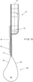
- FIG 7 illustrates yet another embodiment of a valve 10" in an unfolded or open configuration. Similar seals 15 and layers 14, 24, 34 are used as the embodiment illustrated in Figures 1-5 . However, first and second hinge elements 16"a and 16"b are separated and applied to different layers/panels. The first hinge element 16"a is attached to the opposite side of the base layer 14 from the bubble valve subcomponent 12. The second hinge element 16"b is attached to the first panel 16 of the package 100. In some embodiments (e.g., the first and second hinge elements 16"a and 16"b are typically less than 2,54 cm (one inch) apart), both the first hinge element 16"a and the second hinge element 16"b have an area of reduced thickness 18"a and 18"b, respectively.
- the operation of the valve 10" is substantially similar to that of valve 10.
- the folded or closed configuration of valve 10" is similar to that illustrated in Figures 2 and 5 in that the folded or closed configuration restricts or eliminates flow through the channel 17 and fluid outlet or exit 13.
- Figure 8 illustrates a method 200 for manufacturing valves 10, 10', 10" of the present disclosure.
- the various components of valve 10 are typically constructed of polymeric material, but are not limited thereto.
- the bubble valve subcomponent 12 is made from the base layer 14 as provided from base layer unwind 202 and bubble layer 24 as provided from bubble layer unwind 204 with bubble thermoforming by first bubble layer thermoformer 206.
- Bubble layer 24 is sealed along predetermined areas (such as the edges, in order to leave the central area of the bubble free of thermoforming between base layer 14 and bubble layer 24) to base layer 14 by bubble to base ultrasonic sealer 209.
- Channel layer 34 is provided from channel layer unwind 208 with bubble thermoforming by second bubble layer thermoformer 210.
- Channel seal 15 is created by an ultrasonic sealer 212 or other means for sealing known in the art.
- Thermoformers 206, 210, or other means for forming polymeric material known in the art, are used to create shapes of the bubble valve subcomponent 12.
- the hinge element 16 is attached to the bubble valve subcomponent 12 by a hinge sealer 220, creating the valve 10, 10', 10".
- the hinge element 16 is applied and attached to the subcomponent 12 in a machine direction (i.e., in the direction indicated by "Material Flow" in Figure 8 ).
- the hinge element 16' is applied and attached to the bubble valve subcomponent 12 in a transverse direction.
- the valve 10" illustrated in Figure 7 only a portion of the hinge element 16" (i.e., the first hinge element 16"a) is applied and attached to the bubble valve subcomponent 12; the second hinge element 16"b is applied to the first panel 40 later (e.g., when the valve 10" is inserted and sealed to the package 100).
- the hinge sealer 220 Further similar variations are illustrated in 9-11C and require variations in the hinge sealer 220 in order to attach the interlocking element assemblies.
- the finished valves 10, 10', 10" are spooled onto finished valve rewind 222.
- the hinge element 16' may be oriented transversely (i.e., perpendicular to the flow path) on base layer 14 (i.e., on the opposite side from protruding or bubble element 12).
- valve 10 includes interlocking element assemblies 16" arranged on lateral sides of protruding element 12 and the associated flow path, and parallel thereto. As shown in Figure 10B , the valve 10 can be folded along protruding element 12 and the associated flow path, thereby bringing together the two interlocking element assemblies 16" to interlock with each other.
- an interlocking element assembly 16′′′ can be placed immediately downwardly adjacent from the fluid outlet or exit 13, on the opposite side from the protruding element 12 (i.e., base layer 14), and perpendicular to the flow path.
- Interlocking element assembly 16"" is placed immediately below the protruding element 12 on the same side as protruding element 12 (i.e., channel layer 34), and perpendicular to the flow path.
- an interlocking element assembly 16′′′ can be placed immediately downwardly adjacent from the fluid outlet or exit 13, on the same side as protruding element 12 (i.e., channel layer 34), and perpendicular to the flow path.
- interlocking element assembly 16 ⁇ is placed below the protruding element 12 on the opposite side from protruding element 12 (i.e., base layer 14), and perpendicular to the flow path.
- the embodiment of Figure 11A can be rolled so as to conceal the fluid outlet or exit 13 and interlocking element assemblies 16′′′ and 16 ⁇ are joined or interlocked with each other.
- the embodiment of Figure 11B can be rolled to achieve the configuration analogous to that of Figure 11C .
- Figure 12 illustrates the valve 10 of Figure 1 , incorporated into a package 100, wherein the base layer 14 is sealed to the first panel 40 of package 100 and the channel layer 34 is sealed to the second panel 60 of package 100.
- the first panel 40 includes a cut-out area 42 through which the hinge element 16 extends, thereby exposing the interlocking elements of hinge element 16 and allowing the configuration to be folded along area of reduced thickness 18, thereby allowing the upper and lower portions of hinge element 16 to interlock with each other.
- the portions of first panel 40 adjacent to the cut-out area 42 are sealed to first panel 40, throughout a periphery of cut-out area 42, to preserve hermeticity.
- Figure 13 illustrates a valve 10 similar to that of Figures 1 and 12 , except that the first panel 40 is sealed to the base layer 14 of valve 10 and the hinge element 16, including area of reduced thickness 1, originally as a separate element, is sealed or otherwise attached to the external surface of first panel 40. No cut-out area 42 (as shown in Figure 12 ) is necessary in the embodiment illustrated in Figure 13 . That is, a portion of first panel 40 is positioned and sealed between a portion of the valve 10 and the hinge element 16.
Description
- The present disclosure relates to a flexible valve, wherein the valve can be folded and sealed for containing liquids within flexible packaging in combination with a flexible to semi-rigid container. The valve includes a channel formed between a bubble element and a channel layer which is closed whenever the valve is folded and sealed.
- Traditional packaging in the food/beverage, personal care and household care industries is primarily a combination of a rigid bottle or semi-flexible tube with a rigid fitment or cap of varying dispense types. Transition to flexible pouches for the main body of the container has continued to utilize similar, still rigid, fitments. There exists a need within these industries to complete the transition in order to create a fully flexible solution. Such a solution would improve functionality by representing both a flow control mechanism and re-close feature, enhance the overall sustainability profile and cost reduction of the packaging through material reduction and operational efficiency gains, and improved performance expectations in the growing e-commerce market.
- Protruding element valves, or bubble valves are known in the art. They are frequently used with flexible to semi-rigid containers. While these valves have generally been satisfactory for their intended uses, further improvements are sought.
- Representative embodiments of a bubble valve or a pressure-activated valve are disclosed in
PCT/US2018/037461 entitled "Pouch Flip-Top for Bubble Valve Applications," filed on June 14, 2018 ;PCT/US2017/61500 entitled "Bubble Valve for Flexible Packaging," filed on November 14, 2017 ;U.S. Patent No. 9,963,284 entitled "Package Valve Closure System and Method," issued on May 8, 2018 to Steele U.S. Patent No. 8,613,547 entitled "Packages Having Bubble-Shaped Closures," issued on December 24, 2013 to Steele ; andU.S. Patent No. 7,207,717 entitled "Package Having a Fluid Actuated Closure," issued on April 24, 2007 to Steele .DE202004000591U1 relates to a packing that consists of two parts of plastic, aluminium or composite material interconnected along the edges forming a holding space for the contents which can be removed through a withdrawal opening. In one embodiment, the contents exit the package through a channel having a constiction, which can be considered a valve as in the preamble of appended claims 1 and 4.US4328912A relates to a self-contained valved package for a fluent commodity, and more particularly, a package with a depression/impression valve in the wall thereof.EP2612825A1 relates to a hair colorant container in the form of a flexible sachet having a laminate structure for storing a hair colorant component. - It is therefore an object of the present disclosure to provide improved closing and sealing for valves for flexible containers, namely bubble valves. This object is reached, according to the invention, in valves provided with a folding hinge by the features of appended claim 1, and in valves provided with interlocking elements for maintaining them folded by the features of appended claim 4.
- The valve includes a base layer, with a bubble formed between the base layer and a bubble layer. A channel is formed between the bubble layer and a channel layer. A hinge element or separate interlocking assemblies are provided to allow the valve to be closed and secured in a folded configuration. That is, the folding and sealing of the valve caused the channel including the fluid outlet to be closed.
- The disclosed embodiments provide additional re-close functionality to provide added security desired by consumers in use cases where the package may leak should it be subjected to errant external pressure (such as in a purse, backpack or otherwise being transported). Consumer research has shown that there is a preference to perform a manual action to achieve a sense that the package is truly closed in those use cases. Therefore, the design of this valve includes the same structure and functionality in terms of the multi-layer film construction serving the role of flow control.
- Further objects and advantages of the disclosure will become apparent from the following description and from the accompanying drawings, wherein:
-
Figure 1 is a perspective view, partially in phantom, of an open configuration of a first embodiment of the valve of the present disclosure. -
Figure 2 is a perspective view, partially in phantom, of a closed configuration of a first embodiment of the valve of the present disclosure. -
Figure 3 is a front view of a package including an embodiment of the valve of the present disclosure. -
Figure 4 is a side view of an open configuration of a first embodiment of the valve of the present disclosure. -
Figure 5 is a side view of a closed configuration of a first embodiment of the valve of the present disclosure. -
Figure 6 is a perspective view, partially in phantom, of an open configuration of a third embodiment of the valve of the present disclosure. -
Figure 7 is a side view of an open configuration of a second embodiment of the valve of the present disclosure. -
Figure 8 is a schematic of an embodiment of a manufacturing method to produce the valve of the present disclosure. -
Figure 9 is a schematic of an embodiment of the valve of the present disclosure, wherein the locking elements of the zipper are oriented transversely to the flow direction. -
Figures 10A and 10B are schematics of an embodiment of the valve of the present disclosure, in the respective open and closed positions, of an embodiment wherein the fold is in the flow direction and the locking elements are adjacent to the flow path. -
Figures 11A and 11B are side views of an open configuration of an embodiment of the valve of the present disclosure wherein interlocking elements are above positioned transversely above and below the bubble element -
Figure 11C is a side view of a closed configuration of the embodiment of the valve ofFigure 11A . -
Figure 12 is a perspective view of the valve ofFigure 1 , configured with the walls of a pouch or container. -
Figure 13 is a side view of a further embodiment of the valve, configured with the walls of a pouch or container. - Referring now to the drawings in detail wherein like numerals refer to like elements throughout the several views, one sees that
Figures 1 and4 disclose avalve 10 in an unfolded or open configuration. Valve 10 includes a bubble valve subcomponent or protruding or bubble element 12 (with fluid outlet 13). The protruding orbubble element 12 is typically composed of a gas, liquid or fluid captured between abase layer 14 and abubble layer 24 of flexible material. Ahinge element 16 is attached to thebase layer 14 opposite from the protruding orbubble element 12. Thehinge element 16 is, for example, but not limited to, a press-to-close zipper or a self-mating zipper, typically with outwardly extending interlocking elements, and is attached to the base layer 14 (and bubble valve subcomponent or protruding or bubble element 12) either by adhesive or via traditional film sealing methods. The design of thishinge element 16 could likewise be an adhesive element or a form of hook-and-loop closure. -
Channel seals 15, between thechannel layer 34 and at least one of thebase layer 14 andbubble layer 12, define achannel 17 through which fluid flows from a storage volume 80 (typically of a package, pouch, or similar container) to the bubble valve subcomponent or protruding orbubble element 12, as illustrated inFigure 3 . Thevalve 10 is intended to be used in a package orcontainer 100 with thestorage volume 80 defined between afirst panel 40 and asecond panel 60 of polymeric or similar materials. Other materials or features of packages, container or pouches, such as, but not limited to, a bottom panel or a gusset, can be part of thepackage 100. Thevalve 10 is sealed into thepackage 100 between thefirst panel 40 and thesecond panel 60. In one embodiment, thebase layer 14 is sealed to thefirst panel 40 and the channel layer is sealed to thesecond panel 60. Also seeFigures 12 and13 . - The
bubble valve subcomponent 12 includes thebase layer 14, thebubble layer 24, and thechannel layer 34 defining thefluid flow channel 17 between thebubble layer 24 and thechannel layer 34. Thebubble valve subcomponent 12 and its manufacture is described inPCT/US2017/61500 entitled "Bubble Valve for Flexible Packaging," filed on November 14, 2017 . - The
hinge element 16 provides a secondary closure measure for thevalve 10. In normal operation, contents of thestorage volume 80 only pass through thechannel 17 and fluid outlet orexit 13 when a user applies pressure to thestorage volume 80. However, in some instances, an additional or secondary closure is useful, such as when leaving thepackage 100 in a purse or another container where contents of thepackage 100 could make a mess if leaked. Thehinge element 16 provides such a more secure secondary closure when it is in the folded or closed configuration, as illustrated inFigures 2 and5 . Afold 20 develops in at least thelayers channel 17 so no contents may pass through thevalve 10, even if moderate pressure is applied to thestorage volume 80. - In the embodiments of
Figures 1-5 , thehinge element 16 includes a mid-point or central area of reducedthickness 18. The reducedthickness 18 allows folding along a defined hinge line and further reduces obstruction or bulging when the hinge element is folded, as illustrated inFigs. 2 and5 . As shown inFigure 4 , in some embodiments, thehinge element 16 further includes at least one ramped area 19 (e.g., one on each side of the central area of reduced thickness 18) to further facilitate closure of thehinge element 16. The fold oflayers thickness 18, which acts as a hinge point. Theentire valve 10 can be folded back upon itself and snapped into a fixed position with thechannel 17 now kinked and the flow more reliably cutoff or terminated. When desired, the end of thevalve 10 can be pulled, thehinge element 16 releases and returns to the unfolded or open configuration illustrated inFigures 1 and4 . The user can again squeeze thepouch 80 as before to dispense products from thestorage volume 80 in the pouch through thechannel 17 and fluid outlet orexit 13. - While the embodiments illustrated in
Figures 1 through 5 show hinge element 16 parallel and aligned with the center of the protrudingelement 12, other alignments are possible. For example,Figure 6 illustrates an open configuration of valve 10' with hinge elements 16'a and 16'b that are perpendicular to the protrudingelement 12.Similar seals 15 and layers 14, 24, 34 are used as the embodiment illustrated inFigures 1-5 . Both hinge elements 16'a and 16'b are attached to thebase layer 14 opposite of the protruding orbubble element 12. The first hinge element 16'a is attached proximate to the protruding orbubble element 12. The second hinge element 16'b is attached proximate to thechannel 17. As the hinge elements 16'a, 16'b are separate pieces, a central area of reducedthickness 18 is not needed. The first and second hinge elements 16'a and 16'b include interlocking elements so that the first and second hinge elements 16'a and 16'b can interlock with each other, thereby holding the valve 10' in a folded and closed configuration The operation of the valve 10' is substantially similar to that ofvalve 10. The folded or closed configuration of valve 10' is similar to that illustrated inFigures 2 and5 . -
Figure 7 illustrates yet another embodiment of avalve 10" in an unfolded or open configuration.Similar seals 15 and layers 14, 24, 34 are used as the embodiment illustrated inFigures 1-5 . However, first andsecond hinge elements 16"a and 16"b are separated and applied to different layers/panels. Thefirst hinge element 16"a is attached to the opposite side of thebase layer 14 from thebubble valve subcomponent 12. Thesecond hinge element 16"b is attached to thefirst panel 16 of thepackage 100. In some embodiments (e.g., the first andsecond hinge elements 16"a and 16"b are typically less than 2,54 cm (one inch) apart), both thefirst hinge element 16"a and thesecond hinge element 16"b have an area of reducedthickness 18"a and 18"b, respectively. The operation of thevalve 10" is substantially similar to that ofvalve 10. The folded or closed configuration ofvalve 10" is similar to that illustrated inFigures 2 and5 in that the folded or closed configuration restricts or eliminates flow through thechannel 17 and fluid outlet orexit 13. -
Figure 8 illustrates amethod 200 formanufacturing valves valve 10 are typically constructed of polymeric material, but are not limited thereto. First, thebubble valve subcomponent 12 is made from thebase layer 14 as provided from base layer unwind 202 andbubble layer 24 as provided from bubble layer unwind 204 with bubble thermoforming by firstbubble layer thermoformer 206.Bubble layer 24 is sealed along predetermined areas (such as the edges, in order to leave the central area of the bubble free of thermoforming betweenbase layer 14 and bubble layer 24) tobase layer 14 by bubble to baseultrasonic sealer 209.Channel layer 34 is provided from channel layer unwind 208 with bubble thermoforming by secondbubble layer thermoformer 210.Channel seal 15 is created by anultrasonic sealer 212 or other means for sealing known in the art.Thermoformers bubble valve subcomponent 12. Then, thehinge element 16 is attached to thebubble valve subcomponent 12 by ahinge sealer 220, creating thevalve valve 10 illustrated inFigures 1-5 , thehinge element 16 is applied and attached to thesubcomponent 12 in a machine direction (i.e., in the direction indicated by "Material Flow" inFigure 8 ). In another embodiment, such as, but not limited to, the valve 10' illustrated inFigure 6 , the hinge element 16' is applied and attached to thebubble valve subcomponent 12 in a transverse direction. In yet another embodiment, such as, but not limited to, thevalve 10" illustrated inFigure 7 , only a portion of thehinge element 16" (i.e., thefirst hinge element 16"a) is applied and attached to thebubble valve subcomponent 12; thesecond hinge element 16"b is applied to thefirst panel 40 later (e.g., when thevalve 10" is inserted and sealed to the package 100). Further similar variations are illustrated in 9-11C and require variations in thehinge sealer 220 in order to attach the interlocking element assemblies. Thefinished valves finished valve rewind 222. - As shown in
Figure 9 , the hinge element 16', including area of reduced thickness 18', may be oriented transversely (i.e., perpendicular to the flow path) on base layer 14 (i.e., on the opposite side from protruding or bubble element 12). - As shown in
Figures 10A and 10B , an embodiment ofvalve 10 includes interlockingelement assemblies 16" arranged on lateral sides of protrudingelement 12 and the associated flow path, and parallel thereto. As shown inFigure 10B , thevalve 10 can be folded along protrudingelement 12 and the associated flow path, thereby bringing together the two interlockingelement assemblies 16" to interlock with each other. - As shown in
Figures 11A , an interlockingelement assembly 16‴ can be placed immediately downwardly adjacent from the fluid outlet orexit 13, on the opposite side from the protruding element 12 (i.e., base layer 14), and perpendicular to the flow path. Interlockingelement assembly 16"" is placed immediately below the protrudingelement 12 on the same side as protruding element 12 (i.e., channel layer 34), and perpendicular to the flow path. Similarly, as shown inFigure 11B . an interlockingelement assembly 16‴ can be placed immediately downwardly adjacent from the fluid outlet orexit 13, on the same side as protruding element 12 (i.e., channel layer 34), and perpendicular to the flow path. Further inFigure 11B , interlocking element assembly 16ʺʺ is placed below the protrudingelement 12 on the opposite side from protruding element 12 (i.e., base layer 14), and perpendicular to the flow path. As shown inFigure 11C , the embodiment ofFigure 11A can be rolled so as to conceal the fluid outlet orexit 13 and interlockingelement assemblies 16‴ and 16ʺʺ are joined or interlocked with each other. The embodiment ofFigure 11B can be rolled to achieve the configuration analogous to that ofFigure 11C . -
Figure 12 illustrates thevalve 10 ofFigure 1 , incorporated into apackage 100, wherein thebase layer 14 is sealed to thefirst panel 40 ofpackage 100 and thechannel layer 34 is sealed to thesecond panel 60 ofpackage 100. Thefirst panel 40 includes a cut-out area 42 through which thehinge element 16 extends, thereby exposing the interlocking elements ofhinge element 16 and allowing the configuration to be folded along area of reducedthickness 18, thereby allowing the upper and lower portions ofhinge element 16 to interlock with each other. The portions offirst panel 40 adjacent to the cut-out area 42 are sealed tofirst panel 40, throughout a periphery of cut-out area 42, to preserve hermeticity. -
Figure 13 illustrates avalve 10 similar to that ofFigures 1 and12 , except that thefirst panel 40 is sealed to thebase layer 14 ofvalve 10 and thehinge element 16, including area of reduced thickness 1, originally as a separate element, is sealed or otherwise attached to the external surface offirst panel 40. No cut-out area 42 (as shown inFigure 12 ) is necessary in the embodiment illustrated inFigure 13 . That is, a portion offirst panel 40 is positioned and sealed between a portion of thevalve 10 and thehinge element 16. - Thus the several aforementioned objects and advantages are most effectively attained. Although preferred embodiments of the invention have been disclosed and described in detail herein, it should be understood that this invention is in no sense limited thereby.
Claims (15)
- A valve (10) for a package (100), comprising:a protruding element (12),a channel layer (34) forming a channel (17) between the protruding element (12) and the channel layer (34), the channel including a fluid outlet (13); anda hinge element (16) attached to the valve, the hinge element (16) having a first configuration and a second configuration wherein, in the first configuration, the hinge element (16) is unfolded and fluid can flow through the channel (17) to the fluid outlet (13) and, in the second configuration, the hinge is folded and fluid is prevented from flowing through the channel (17) to the fluid outlet (13), characterised in that the protruding element (12) is a bubble valve subcomponent including a base layer (14), a bubble layer (24) and the channel layer (34).
- The valve of Claim 1, wherein the hinge element (16) is attached to the base layer (14) on an opposite side of the bubble valve subcomponent.
- The valve of Claim 1, wherein the hinge element (16) includes a central area of reduced thickness (18) thereby providing a fold line for the hinge element in the second configuration.
- A valve (10', 10") for a package (100), comprising:a protruding element (12),a channel layer (34) forming a channel (17) between the protruding element (12) and the channel layer (34), the channel (17) including a fluid outlet (13); andfirst and second interlocking assemblies (16', 16", 16‴) attached to the valve, the first andsecond interlocking assemblies (16', 16", 16‴) having a first configuration and a second configuration wherein, in the first configuration, the first and second interlocking assemblies (16', 16", 16‴) are separated from each other and the valve ( 10', 10") is unfolded and fluid can flow through the channel (17) to the fluid outlet (13) and, in the second configuration, the first and second interlocking assemblies (16', 16", 16‴) are interlocked with each other so that the valve is folded and fluid is prevented from flowing through the channel (17) to the fluid outlet (13),characterised in that the protruding element (12) is a bubble valve subcomponent including a base layer (14), a bubble layer (24) and the channel layer (34).
- A package (100) comprising:a storage volume (80) defined between a first panel (40) and a second panel (60); anda valve (10, 10') accoding to claim 1 or claim 4 between the first panel (40) and the second panel (16).
- The package of Claim 5,
wherein the hinge element (16) includes a central area of reduced thickness (18). - The valve of claim 3 or the package of Claim 6,
wherein the hinge element (16) includes at least one ramped area (19) proximate the central area of reduced thickness (18). - The valve of claim 1 or the package of Claim 5,
wherein the hinge element (16) is a zipper. - The valve or the package of Claim 8,
wherein the zipper is a self- mating zipper. - The package of Claim 5,
wherein the hinge element is (16) attached to the valve. - The package of Claim 10,
wherein the hinge element (16) is parallel and aligned with the protruding element (12). - The valve of claim 1 or the package of Claim 5,
wherein the hinge element (16) includes a first hinge element (16'a) and a second hinge element (16'b). - The package of Claim 12,
wherein the first hinge element (16'a) is attached to a portion of the protruding element (12), and the second hinge element (16'b) is attached to a portion of the package (100). - The package of Claim 13,
wherein the first (16'a) and second (16'b) hinge elements are perpendicular to the protruding element (12). - The package of Claim 12,
wherein the first hinge element (16'a) is attached to the protruding element (12), and the second hinge element (16'b) is attached to the first panel (40) of the package (100).
Applications Claiming Priority (2)
| Application Number | Priority Date | Filing Date | Title |
|---|---|---|---|
| US201862720323P | 2018-08-21 | 2018-08-21 | |
| PCT/US2019/046819 WO2020041130A1 (en) | 2018-08-21 | 2019-08-16 | Fold and seal flexible valves |
Publications (2)
| Publication Number | Publication Date |
|---|---|
| EP3841032A1 EP3841032A1 (en) | 2021-06-30 |
| EP3841032B1 true EP3841032B1 (en) | 2023-07-12 |
Family
ID=69583827
Family Applications (1)
| Application Number | Title | Priority Date | Filing Date |
|---|---|---|---|
| EP19762047.9A Active EP3841032B1 (en) | 2018-08-21 | 2019-08-16 | Fold and seal flexible valves |
Country Status (7)
| Country | Link |
|---|---|
| US (1) | US20200062465A1 (en) |
| EP (1) | EP3841032B1 (en) |
| JP (1) | JP2021534045A (en) |
| CN (1) | CN112955385A (en) |
| BR (1) | BR112021003120A2 (en) |
| MX (1) | MX2021000589A (en) |
| WO (1) | WO2020041130A1 (en) |
Families Citing this family (3)
| Publication number | Priority date | Publication date | Assignee | Title |
|---|---|---|---|---|
| US10988295B1 (en) * | 2017-06-15 | 2021-04-27 | Illinois Tool Works Inc. | Pouch flip-top for bubble valve applications |
| US20210347536A1 (en) * | 2020-05-05 | 2021-11-11 | Illinois Tool Works Inc. | Flexible package assembly and method of manufacturing |
| CN113974776B (en) * | 2021-11-17 | 2023-06-02 | 上海腾复医疗科技有限公司 | Pusher and thrombus aspiration system comprising same |
Family Cites Families (87)
| Publication number | Priority date | Publication date | Assignee | Title |
|---|---|---|---|---|
| US2078326A (en) * | 1935-12-04 | 1937-04-27 | Charles E Howett | Liquid projecting device |
| US3224640A (en) * | 1962-06-21 | 1965-12-21 | Wayne Rodgers V | Reclosable package |
| US3160323A (en) * | 1963-04-05 | 1964-12-08 | Leonard R Weisberg | Containers with internal, interlocking protrusions |
| US3278085A (en) * | 1964-06-02 | 1966-10-11 | Brown Royce Edward | Re-sealable sachet container |
| US3315849A (en) * | 1965-09-15 | 1967-04-25 | Albert M Herzig | Closure for collapsible tube |
| US3635376A (en) * | 1970-06-05 | 1972-01-18 | Hellstrom Harold R | Quick-open flexible package |
| US4163509A (en) * | 1977-02-22 | 1979-08-07 | The Procter & Gamble Company | Squeeze dispenser with self closing valve |
| US4328912A (en) * | 1978-06-26 | 1982-05-11 | Haggar Theodore | Self-contained valved package |
| US4236652A (en) * | 1979-03-20 | 1980-12-02 | American Can Company | Dispenser package |
| US5833061A (en) * | 1981-10-30 | 1998-11-10 | Storandt; Duane L. | Applicator mitt |
| US4679688A (en) * | 1983-09-13 | 1987-07-14 | Soederholm Jan | Package for risk samples |
| US4592493A (en) * | 1984-10-15 | 1986-06-03 | Unette Corporation | Reclosable dispenser |
| KR870700052A (en) * | 1985-03-08 | 1987-02-28 | 도시오 나까무라 | Packing bags |
| US4657159A (en) * | 1985-08-06 | 1987-04-14 | Grant Alan H | Meniscus-shaped container |
| US4805767A (en) * | 1987-06-18 | 1989-02-21 | Newman Duncan A C | Package system |
| US5241150A (en) * | 1989-10-02 | 1993-08-31 | Minnesota Mining And Manufacturing Company | Microwave food package |
| US5072855A (en) * | 1990-02-22 | 1991-12-17 | Herzig Albert M | Curved semi-rigid plastic rib closure for flexible containers |
| US6348246B1 (en) * | 1992-01-09 | 2002-02-19 | Arnold B. Finestone | Laminate sheeting for pouches |
| US5248537A (en) * | 1992-07-22 | 1993-09-28 | Danbury Printing & Litho, Inc. | Non-contaminating fragrance releasing insert for magazines |
| BR9407950A (en) * | 1993-11-01 | 1996-11-26 | Procter & Gamble | Self-closing liquid dispenser packaging |
| US5529224A (en) * | 1993-11-01 | 1996-06-25 | The Procter & Gamble Company | Self-closing liquid dispensing package |
| US5761884A (en) * | 1995-11-29 | 1998-06-09 | Arkmount Systems Inc. | Method of making a filled container |
| NL1002300C2 (en) * | 1996-02-12 | 1997-08-13 | Louis Rinze Henricus Willemsen | Compressible container for liquid material. |
| US5928748A (en) * | 1997-01-31 | 1999-07-27 | Arcade, Inc. | Laminated page and method for making same |
| GB9715008D0 (en) * | 1997-07-17 | 1997-09-24 | Tecmark Limited | Valve means |
| US5839609A (en) * | 1997-08-27 | 1998-11-24 | Colgate-Palmolive Company | Thermoformed pack with ridge valve |
| FR2778639B1 (en) * | 1998-05-18 | 2000-07-28 | Valois Sa | SAMPLE TYPE SPRAYING DEVICE |
| FR2791645B1 (en) * | 1999-04-02 | 2001-06-15 | Valois Sa | FLUID PRODUCT SAMPLE FOR PRESS |
| OA12090A (en) * | 1999-11-19 | 2006-05-04 | Sanford Redmond | Reclosable dispenser package, reclosable outlet forming structure and method and apparatus for making same. |
| US6783030B2 (en) * | 1999-11-19 | 2004-08-31 | Sanford Redmond | Easy opening sealed containment and dispensing package |
| US6357631B1 (en) * | 2000-04-06 | 2002-03-19 | Colgate-Palmolive Company | Container with formed memory valve |
| US6783035B2 (en) * | 2001-07-19 | 2004-08-31 | Valois S.A.S. | Fluid product dispenser |
| US20030230599A1 (en) * | 2001-11-14 | 2003-12-18 | Valois Sas | Spring and dispenser comprising such a spring |
| US6997355B2 (en) * | 2001-11-14 | 2006-02-14 | Volois S.A.S. | Fluid product dispenser |
| US6805263B2 (en) * | 2001-11-20 | 2004-10-19 | Valois Sas | Fluid product dispenser |
| US6769579B2 (en) * | 2002-10-07 | 2004-08-03 | Valois Sas | Fluid dispenser |
| US20040084554A1 (en) * | 2002-10-24 | 2004-05-06 | Valois Sas | Fluid dispenser |
| US20040135005A1 (en) * | 2002-12-23 | 2004-07-15 | Valois Sas | Fluid dispenser |
| FR2852930B1 (en) * | 2003-03-27 | 2005-06-24 | Valois Sas | FLUID PRODUCT DISPENSER. |
| US6767151B1 (en) * | 2003-04-22 | 2004-07-27 | Richard L. Owens | Dispenser/spreader article for spackling and paste |
| US7004354B2 (en) * | 2003-06-24 | 2006-02-28 | William Anthony Harper | Hand sanitizing packet and methods |
| US7314328B2 (en) * | 2003-07-28 | 2008-01-01 | Liberatore Raymond A | Spreader |
| US7007823B2 (en) * | 2003-08-05 | 2006-03-07 | Mark Jackson | Toothpaste dispensing system |
| DE202004000591U1 (en) * | 2004-01-16 | 2004-03-18 | Klocke Verpackungs-Service Gmbh | Packing has adhesive label fitted at least on one part of packing and by which removal section containing withdrawal opening is connected to one side of packing through bending over by about 180 degrees |
| DE202004004857U1 (en) * | 2004-03-25 | 2004-05-27 | Klocke Verpackungs-Service Gmbh | Packaging with applicator for applying thin and pasty media |
| US8104986B2 (en) * | 2004-07-16 | 2012-01-31 | Nash Alan E | Liquid applicator |
| AU2005304853B2 (en) * | 2004-11-05 | 2011-02-10 | Mark Steele | Package having a fluid actuated closure |
| US8613547B2 (en) | 2004-11-05 | 2013-12-24 | Mark Steele | Packages having bubble-shaped closures |
| US7513397B2 (en) * | 2004-11-24 | 2009-04-07 | Holopack International Corp. | Dispensing container |
| US20060191929A1 (en) * | 2005-02-28 | 2006-08-31 | Berg Charles J Jr | Flexi-resilient to rigid container including horizontally hinged sides |
| US7565987B2 (en) * | 2005-08-31 | 2009-07-28 | Kimberly-Clark Worldwide, Inc. | Pull tab activated sealed packet |
| US20070068965A1 (en) * | 2005-09-26 | 2007-03-29 | Von Flotow Andreas H | Re-closable flexible dispensing package providing a seal |
| US20070131342A1 (en) * | 2005-12-08 | 2007-06-14 | Kimberly-Clark Worldwide, Inc. | Method of making, using and applying a composition to an exposed surface |
| MX2008012293A (en) * | 2006-03-31 | 2008-10-08 | Wyeth Corp | A tear and spill resistant package for dispensing liquids in a controlled manner. |
| DK2007331T3 (en) * | 2006-04-11 | 2017-06-19 | Coloplast As | COLLECTION BAG WITH IMPROVED CLOSING AND PROCEDURE FOR PREPARING SUCH A COLLECTION BAG |
| US20090204096A1 (en) * | 2006-07-18 | 2009-08-13 | Satsumaya Syouten Co., Ltd. | Portable drug solution container |
| US8418883B2 (en) * | 2006-12-20 | 2013-04-16 | Momentive Performance Materials | Packet for viscous material and kit |
| US8061563B1 (en) * | 2007-05-29 | 2011-11-22 | Ags I-Prop, Llc | Flexible pouch with expulsion aid |
| US7946766B2 (en) * | 2007-06-15 | 2011-05-24 | S.C. Johnson & Son, Inc. | Offset closure mechanism for a reclosable pouch |
| US7874731B2 (en) * | 2007-06-15 | 2011-01-25 | S.C. Johnson Home Storage, Inc. | Valve for a recloseable container |
| US8262305B2 (en) * | 2008-03-31 | 2012-09-11 | Kimberly-Clark Worldwide, Inc. | Package and applicator for liquid or semi-liquid composition |
| US20090266036A1 (en) * | 2008-04-24 | 2009-10-29 | Kraft Foods Global Brand Llc | Flexible package having an automatic closure feature |
| FR2930460B1 (en) * | 2008-04-25 | 2010-05-28 | Valois Sas | FRAGRANCE DISTRIBUTOR. |
| TWI556845B (en) * | 2008-12-30 | 2016-11-11 | 大塚美國製藥股份有限公司 | Fluid application device and method |
| US8398324B2 (en) * | 2009-03-19 | 2013-03-19 | Jbl Radical Innovations, Llc | Vial for delivering contents onto a substrate |
| US9061796B2 (en) * | 2009-04-23 | 2015-06-23 | H.J. Heinz Company | Multi-function condiment container |
| JP5976539B2 (en) * | 2009-08-24 | 2016-08-23 | アキ, インコーポレイテッドAki, Inc. | How to make an integrated package |
| US9272830B2 (en) * | 2009-08-24 | 2016-03-01 | Aki, Inc. | Unitized package of card and fluid vessel |
| JP2013503019A (en) * | 2009-08-30 | 2013-01-31 | アクティヴパック, インコーポレイテッド | Administration device and product administration method |
| US20120187182A1 (en) * | 2009-10-08 | 2012-07-26 | Illinois Tool Works Inc. | Carton with plastic reclosable header |
| EP2499060B1 (en) * | 2009-11-12 | 2013-10-02 | MDS Global Holding Ltd. | Container for dispensing a substance |
| DE102010031734A1 (en) * | 2010-07-21 | 2012-01-26 | Multivac Sepp Haggenmüller Gmbh & Co. Kg | Packaging for a liquid, powdery or pasty product |
| CN101913455A (en) * | 2010-07-31 | 2010-12-15 | 杜宪勇 | Card-type flexible package reclosing device |
| EP2630075A4 (en) * | 2010-10-22 | 2015-04-08 | Py Daniel C | Pouch connector and related method |
| FR2971770B1 (en) * | 2011-02-21 | 2013-03-22 | Eric Noel | PACKAGED INTERNAL POCKET WITH A BREAKING MEANS |
| US8931664B2 (en) * | 2011-07-27 | 2015-01-13 | Wave Creative Products Inc. | Single use dispenser package |
| US9016521B2 (en) * | 2011-07-27 | 2015-04-28 | Diana Foster | Product dispenser package for personal use |
| US9499309B2 (en) * | 2011-07-28 | 2016-11-22 | Intercontinental Great Brands Llc | Reclosable packaging using a low-tack adhesive fastener |
| EP2612825B1 (en) * | 2012-01-04 | 2017-11-01 | Noxell Corporation | Hair colorant container in the form of a flexible sachet |
| US8950635B2 (en) * | 2012-03-14 | 2015-02-10 | Honey Bee Babies, Llc | Unitary product-dispensing container having a combined cap and feeding/ dosing dispenser |
| EP2925623B1 (en) * | 2012-12-03 | 2017-09-27 | WM. Wrigley Jr. Company | Unitary flexible package |
| USD725264S1 (en) * | 2013-07-02 | 2015-03-24 | Adhezion Biomedical, Llc | Blistered dispenser |
| WO2016147859A1 (en) * | 2015-03-15 | 2016-09-22 | 法基 岡部 | Sealing container |
| CN107531363B (en) * | 2015-04-09 | 2019-12-20 | 马克·斯蒂尔 | Packaging valve closure system and method |
| BR112019022096B1 (en) * | 2017-04-20 | 2023-05-09 | Illinois Tool Works Inc | VALVE TO ALLOW SELECTIVE DISPENSING OF CONTENT FROM A PACKAGING, METHOD TO FORM A VALVE AND PACKAGING TO HOLD AND DISPENSE CONTENT |
| EP3612466B1 (en) * | 2017-04-20 | 2023-09-27 | Illinois Tool Works, Inc. | Profile valve and package for liquid metering and dispensing |
| CN112424077B (en) * | 2018-08-14 | 2022-08-30 | 宝洁公司 | Package with integrated magnetic valve |
-
2019
- 2019-08-16 CN CN201980051671.1A patent/CN112955385A/en active Pending
- 2019-08-16 BR BR112021003120-0A patent/BR112021003120A2/en unknown
- 2019-08-16 US US16/542,622 patent/US20200062465A1/en not_active Abandoned
- 2019-08-16 JP JP2021509221A patent/JP2021534045A/en active Pending
- 2019-08-16 MX MX2021000589A patent/MX2021000589A/en unknown
- 2019-08-16 WO PCT/US2019/046819 patent/WO2020041130A1/en unknown
- 2019-08-16 EP EP19762047.9A patent/EP3841032B1/en active Active
Also Published As
| Publication number | Publication date |
|---|---|
| BR112021003120A2 (en) | 2021-05-11 |
| WO2020041130A1 (en) | 2020-02-27 |
| EP3841032A1 (en) | 2021-06-30 |
| US20200062465A1 (en) | 2020-02-27 |
| CN112955385A (en) | 2021-06-11 |
| MX2021000589A (en) | 2021-04-12 |
| JP2021534045A (en) | 2021-12-09 |
Similar Documents
| Publication | Publication Date | Title |
|---|---|---|
| AU2021201252B2 (en) | Package valve closure system and method | |
| US10479041B2 (en) | Stationary closure device and package | |
| EP3841032B1 (en) | Fold and seal flexible valves | |
| EP3612464B1 (en) | Bubble valve for flexible packaging | |
| US20230056802A1 (en) | Package having a spout reservoir/retaining feature | |
| EP2152597B1 (en) | Packages having fluid-filled chamber closures | |
| DK3177546T3 (en) | CONTAINER FOR FLUIDS |
Legal Events
| Date | Code | Title | Description |
|---|---|---|---|
| STAA | Information on the status of an ep patent application or granted ep patent |
Free format text: STATUS: UNKNOWN |
|
| STAA | Information on the status of an ep patent application or granted ep patent |
Free format text: STATUS: THE INTERNATIONAL PUBLICATION HAS BEEN MADE |
|
| PUAI | Public reference made under article 153(3) epc to a published international application that has entered the european phase |
Free format text: ORIGINAL CODE: 0009012 |
|
| STAA | Information on the status of an ep patent application or granted ep patent |
Free format text: STATUS: REQUEST FOR EXAMINATION WAS MADE |
|
| 17P | Request for examination filed |
Effective date: 20210204 |
|
| AK | Designated contracting states |
Kind code of ref document: A1 Designated state(s): AL AT BE BG CH CY CZ DE DK EE ES FI FR GB GR HR HU IE IS IT LI LT LU LV MC MK MT NL NO PL PT RO RS SE SI SK SM TR |
|
| DAV | Request for validation of the european patent (deleted) | ||
| DAX | Request for extension of the european patent (deleted) | ||
| GRAP | Despatch of communication of intention to grant a patent |
Free format text: ORIGINAL CODE: EPIDOSNIGR1 |
|
| STAA | Information on the status of an ep patent application or granted ep patent |
Free format text: STATUS: GRANT OF PATENT IS INTENDED |
|
| INTG | Intention to grant announced |
Effective date: 20230310 |
|
| RAP3 | Party data changed (applicant data changed or rights of an application transferred) |
Owner name: ILLINOIS TOOL WORKS INC. |
|
| GRAS | Grant fee paid |
Free format text: ORIGINAL CODE: EPIDOSNIGR3 |
|
| GRAA | (expected) grant |
Free format text: ORIGINAL CODE: 0009210 |
|
| STAA | Information on the status of an ep patent application or granted ep patent |
Free format text: STATUS: THE PATENT HAS BEEN GRANTED |
|
| AK | Designated contracting states |
Kind code of ref document: B1 Designated state(s): AL AT BE BG CH CY CZ DE DK EE ES FI FR GB GR HR HU IE IS IT LI LT LU LV MC MK MT NL NO PL PT RO RS SE SI SK SM TR |
|
| P01 | Opt-out of the competence of the unified patent court (upc) registered |
Effective date: 20230606 |
|
| REG | Reference to a national code |
Ref country code: CH Ref legal event code: EP |
|
| REG | Reference to a national code |
Ref country code: DE Ref legal event code: R096 Ref document number: 602019032633 Country of ref document: DE |
|
| REG | Reference to a national code |
Ref country code: IE Ref legal event code: FG4D |
|
| REG | Reference to a national code |
Ref country code: LT Ref legal event code: MG9D |
|
| REG | Reference to a national code |
Ref country code: NL Ref legal event code: MP Effective date: 20230712 |
|
| REG | Reference to a national code |
Ref country code: AT Ref legal event code: MK05 Ref document number: 1586912 Country of ref document: AT Kind code of ref document: T Effective date: 20230712 |
|
| PG25 | Lapsed in a contracting state [announced via postgrant information from national office to epo] |
Ref country code: NL Free format text: LAPSE BECAUSE OF FAILURE TO SUBMIT A TRANSLATION OF THE DESCRIPTION OR TO PAY THE FEE WITHIN THE PRESCRIBED TIME-LIMIT Effective date: 20230712 |
|
| PG25 | Lapsed in a contracting state [announced via postgrant information from national office to epo] |
Ref country code: GR Free format text: LAPSE BECAUSE OF FAILURE TO SUBMIT A TRANSLATION OF THE DESCRIPTION OR TO PAY THE FEE WITHIN THE PRESCRIBED TIME-LIMIT Effective date: 20231013 |
|
| PG25 | Lapsed in a contracting state [announced via postgrant information from national office to epo] |
Ref country code: ES Free format text: LAPSE BECAUSE OF FAILURE TO SUBMIT A TRANSLATION OF THE DESCRIPTION OR TO PAY THE FEE WITHIN THE PRESCRIBED TIME-LIMIT Effective date: 20230712 |
|
| PG25 | Lapsed in a contracting state [announced via postgrant information from national office to epo] |
Ref country code: IS Free format text: LAPSE BECAUSE OF FAILURE TO SUBMIT A TRANSLATION OF THE DESCRIPTION OR TO PAY THE FEE WITHIN THE PRESCRIBED TIME-LIMIT Effective date: 20231112 |
|
| PG25 | Lapsed in a contracting state [announced via postgrant information from national office to epo] |
Ref country code: SE Free format text: LAPSE BECAUSE OF FAILURE TO SUBMIT A TRANSLATION OF THE DESCRIPTION OR TO PAY THE FEE WITHIN THE PRESCRIBED TIME-LIMIT Effective date: 20230712 Ref country code: RS Free format text: LAPSE BECAUSE OF FAILURE TO SUBMIT A TRANSLATION OF THE DESCRIPTION OR TO PAY THE FEE WITHIN THE PRESCRIBED TIME-LIMIT Effective date: 20230712 Ref country code: PT Free format text: LAPSE BECAUSE OF FAILURE TO SUBMIT A TRANSLATION OF THE DESCRIPTION OR TO PAY THE FEE WITHIN THE PRESCRIBED TIME-LIMIT Effective date: 20231113 Ref country code: NO Free format text: LAPSE BECAUSE OF FAILURE TO SUBMIT A TRANSLATION OF THE DESCRIPTION OR TO PAY THE FEE WITHIN THE PRESCRIBED TIME-LIMIT Effective date: 20231012 Ref country code: LV Free format text: LAPSE BECAUSE OF FAILURE TO SUBMIT A TRANSLATION OF THE DESCRIPTION OR TO PAY THE FEE WITHIN THE PRESCRIBED TIME-LIMIT Effective date: 20230712 Ref country code: LT Free format text: LAPSE BECAUSE OF FAILURE TO SUBMIT A TRANSLATION OF THE DESCRIPTION OR TO PAY THE FEE WITHIN THE PRESCRIBED TIME-LIMIT Effective date: 20230712 Ref country code: IS Free format text: LAPSE BECAUSE OF FAILURE TO SUBMIT A TRANSLATION OF THE DESCRIPTION OR TO PAY THE FEE WITHIN THE PRESCRIBED TIME-LIMIT Effective date: 20231112 Ref country code: HR Free format text: LAPSE BECAUSE OF FAILURE TO SUBMIT A TRANSLATION OF THE DESCRIPTION OR TO PAY THE FEE WITHIN THE PRESCRIBED TIME-LIMIT Effective date: 20230712 Ref country code: GR Free format text: LAPSE BECAUSE OF FAILURE TO SUBMIT A TRANSLATION OF THE DESCRIPTION OR TO PAY THE FEE WITHIN THE PRESCRIBED TIME-LIMIT Effective date: 20231013 Ref country code: FI Free format text: LAPSE BECAUSE OF FAILURE TO SUBMIT A TRANSLATION OF THE DESCRIPTION OR TO PAY THE FEE WITHIN THE PRESCRIBED TIME-LIMIT Effective date: 20230712 Ref country code: ES Free format text: LAPSE BECAUSE OF FAILURE TO SUBMIT A TRANSLATION OF THE DESCRIPTION OR TO PAY THE FEE WITHIN THE PRESCRIBED TIME-LIMIT Effective date: 20230712 Ref country code: AT Free format text: LAPSE BECAUSE OF FAILURE TO SUBMIT A TRANSLATION OF THE DESCRIPTION OR TO PAY THE FEE WITHIN THE PRESCRIBED TIME-LIMIT Effective date: 20230712 |
|
| PG25 | Lapsed in a contracting state [announced via postgrant information from national office to epo] |
Ref country code: PL Free format text: LAPSE BECAUSE OF FAILURE TO SUBMIT A TRANSLATION OF THE DESCRIPTION OR TO PAY THE FEE WITHIN THE PRESCRIBED TIME-LIMIT Effective date: 20230712 |
|
| REG | Reference to a national code |
Ref country code: DE Ref legal event code: R119 Ref document number: 602019032633 Country of ref document: DE |
|
| REG | Reference to a national code |
Ref country code: CH Ref legal event code: PL |
|
| PG25 | Lapsed in a contracting state [announced via postgrant information from national office to epo] |
Ref country code: LU Free format text: LAPSE BECAUSE OF NON-PAYMENT OF DUE FEES Effective date: 20230816 |