EP2152143B1 - System und verfahren zur beleuchtung und fixierung mit ophthalmischen diagnoseinstrumeten - Google Patents
System und verfahren zur beleuchtung und fixierung mit ophthalmischen diagnoseinstrumeten Download PDFInfo
- Publication number
- EP2152143B1 EP2152143B1 EP08746889A EP08746889A EP2152143B1 EP 2152143 B1 EP2152143 B1 EP 2152143B1 EP 08746889 A EP08746889 A EP 08746889A EP 08746889 A EP08746889 A EP 08746889A EP 2152143 B1 EP2152143 B1 EP 2152143B1
- Authority
- EP
- European Patent Office
- Prior art keywords
- target
- eye
- patient
- optical
- display
- Prior art date
- Legal status (The legal status is an assumption and is not a legal conclusion. Google has not performed a legal analysis and makes no representation as to the accuracy of the status listed.)
- Active
Links
Images


Classifications
-
- A—HUMAN NECESSITIES
- A61—MEDICAL OR VETERINARY SCIENCE; HYGIENE
- A61B—DIAGNOSIS; SURGERY; IDENTIFICATION
- A61B3/00—Apparatus for testing the eyes; Instruments for examining the eyes
- A61B3/0091—Fixation targets for viewing direction
-
- A—HUMAN NECESSITIES
- A61—MEDICAL OR VETERINARY SCIENCE; HYGIENE
- A61B—DIAGNOSIS; SURGERY; IDENTIFICATION
- A61B3/00—Apparatus for testing the eyes; Instruments for examining the eyes
- A61B3/10—Objective types, i.e. instruments for examining the eyes independent of the patients' perceptions or reactions
- A61B3/103—Objective types, i.e. instruments for examining the eyes independent of the patients' perceptions or reactions for determining refraction, e.g. refractometers, skiascopes
Definitions
- Embodiments of the present invention provide devices, and methods to measure and diagnose optical properties of an eye. Although specific mention is made to wavefront measurements of the eye, embodiments of the present invention can be used with many instruments that measure and/or treat optical properties of the eye, for example auto refractors and laser eye surgery systems.
- User interface input devices 62 may include a keyboard, pointing devices such as a mouse, trackball, touch pad, or graphics tablet, a scanner, foot pedals, a joystick, a touchscreen incorporated into the display, audio input devices such as voice recognition systems, microphones, and other types of input devices.
- User input devices 62 with often be used to download a computer executable code from a tangible storage media 29 embodying any of the methods of the present invention.
- use of the term "input device” is intended to include a variety of conventional and proprietary devices and ways to input information into computer system 20.
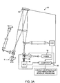
- Wavefront measurement system 10 includes an image source 32, such as a laser, to project a point source onto the retina, and display 80 with target 84 that presents a visual stimulus to the patient, such as a moving target, to relax accommodation of the eye.
- image source 32 such as a laser
- target 84 that presents a visual stimulus to the patient, such as a moving target, to relax accommodation of the eye.
- Eye E generally defines an anterior orientation ANT and a posterior orientation POS.
- Image source 32 generally projects an image in a posterior orientation through optical tissues 34 onto retina R as indicated in Figure 3 .
- Optical tissues 34 again transmit image 44 from the retina anteriorly toward wavefront sensor 36.
- Image 44 actually formed on retina R may be distorted by any imperfections in the eye's optical system when the image source is originally transmitted by optical tissues 34.
- image source projection optics 46 may be configured or adapted to decrease any distortion of image 44.
- a series of wavefront sensor data readings may be taken.
- a time series of wavefront data readings may help to provide a more accurate overall determination of the ocular tissue aberrations.
- a plurality of temporally separated wavefront sensor measurements can avoid relying on a single snapshot of the optical characteristics as the basis for a refractive correcting procedure.
- Still further alternatives are also available, including taking wavefront sensor data of the eye with the eye in differing configurations, positions, and/or orientations.
- a patient will often help maintain alignment of the eye with wavefront measurement system 30 by focusing on a fixation target, as described in U.S. Patent No. 6,004,313 .
- a fixation target By varying a position of the fixation target so as to change a distance from the eye to the target as described in that reference, optical characteristics of the eye may be determined while the eye accommodates or adapts to image a field of view at a varying distance and/or angles.
- the components of an embodiment of a wavefront measurement system for measuring the eye and ablations comprise elements of a VISX WaveScan ® system, available from VISX, Incorporated of Santa Clara, California.
- VISX WaveScan ® system available from VISX, Incorporated of Santa Clara, California.
- One embodiment includes a WaveScan ® system with a deformable mirror as described above.
- An alternate embodiment of a wavefront measuring system is described in U. S. Patent No. 6,271,915 .
- Wavefront measurement systems suitable for incorporation of embodiments of the present invention include the Zyoptix ® Systems commercially available from Bausch & Lomb of Rochester New York; the OPD Scan IITM commercially available from NIDEK of Gamagori, Japan; the WASCATM analyzer, commercially available from Carl Zeiss Meditec, Inc. of Dublin, California; the iTraceTM, commercially available from Tracey Technologies, Inc. of Houston, TX; the ORKTM system from Schwind; and the
- Adjustable target 114 transmits an image along optical path 112R, with the light being profiled by an aperture A having a field stop, the light then being collimated by an adjustable focal-length lens L before being directed along the optical path using a prism P.
- the light is re-collimated by lenses L to go through the optics of the eye, primarily the cornea and the lens of the eye, so as to form an image on the retina.
- an initial total ocular aberration measurement can be taken of eye 116R, often using adjustable target 114 in a distant viewing configuration. Using this initial measurement, the deformable mirror can be configured to compensate for ocular aberrations.
- adjustable target 114 is moved to an intermediate distance, any residual accommodation may kick in. With a near light source, the full residual accommodation of the eye may be employed when the patient tries to focus on the target, particularly if the target is at or beyond the near viewing accommodation of the eye.
- the Hartmann-Shack wavefront sensor HS measures the aberration of the eye while the lens of the eye is in its nearest viewing configuration, the total change in the ocular aberration between the distance viewing measurement and the near viewing measurements allows an objective determination of a residual accommodation.
- the eye can, but need not necessarily be fogged by gradually increasing the viewing distance to just beyond the accommodation range.
- predetermined viewing distances such as a distance viewing configuration of greater than 8', optionally at about 20'; and a near viewing configuration of less than 5', often being less than 2', and optionally being about 16" may be sufficient for measuring the change in ocular aberration for the eyes of some or all patients, particularly patients at or above a predetermined age (such as over an age of 30, often being over an age of 45).
- adjustable target 114 is not under the control of computer control system 122 (by coupling of an input of the adjustable target to a control signal output of the computer system), then the adjustable target will often transmit a signal to a computer so as to indicate the viewing configuration of the target during measurements.
- adjustment of the brightness level may be effected using one or more ambient lights 124, with the input for adjusting brightness level optionally being coupled to ambient light 124 and an adjustable brightness light source of target 114, or by using a fixed brightness light source within target 114 in combination with ambient light 124 so as to alter an overall brightness level to eyes 116R, 116L.
- Adjustment of the ambient and/or target viewing brightness level allows apparatus 110 to measure pupil size and/or aberrations under different brightness level viewing conditions. As the brightness level of the viewing target or ambient light increases, pupil size decreases. Additionally, as eyes adjust from a near viewing distance to a far viewing distance, pupil size may decrease. Apparatus 110 may be used in a room having a low or darkened room lighting to facilitate low brightness level measurements, or a housing or drape may be provided to limit the effect of room lighting on the eye. In some embodiments, ambient light may be used to adjust and/or control pupil size.
- Measurement of eyes at a matrix of different viewing conditions will facilitate, customized prescriptions for the patient's eyes.
- pupil measurements and/or aberration measurements will be made at a plurality of viewing conditions, preferably at least 2, preferably at least 3 or more different viewing conditions, ideally at 4 or more viewing conditions. This may facilitate development or selection of presbyopia and other refractive defect mitigating shapes for the eye which are well-suited for typical tasks at multiple viewing conditions.
- the prescriptive shape may be selected so as to provide good acuity for reading, (often without reading glasses) at a relatively bright, near viewing configuration of the pupil and ocular optics; ideally while also providing good visual acuity for reading signs at a far distance and/or dashboard instruments at an intermediate distance when driving at night; while also maintaining the best available distance viewing acuity under bright-light conditions.
- more than one accommodation of each eye 116R, 116L may be measured so as to indicate the adjustability of the lens and other ocular optics of the eye at different lighting conditions.
- adjustable target 114 will often be adjustable within a range of about 60,96 cm [2] to about 243,84 [8] feet, often being adjustable within a range from about 81,28 cm [32] inches to about 152,4 cm [5] feet.
- Actual linear distance along optical path 112R between eye 116R and adjustable target 114 need not necessarily correspond with the optical viewing distance, as lenses L, mirrors M, or other optical elements may be used to adjust the optical viewing distance.
- the light source and field stop of adjustable target 114 may remain the same actual linear distance apart throughout the near, intermediate, and distance viewing configurations using a zoom lens arrangement, selectable turret, or the like.
- adjustable target 114 may also include any of a wide variety of verification test image shapes such as one or more letters of a Snellen eye chart, a landscape image (particularly for distance viewing), a portrait image (such as for intermediate viewing) small text or detail image (for example, for verifying near visual acuity) and the like.
- deformable mirror 118R may comprise a system such as that available commercially from XINETICS, INC. located at Devens, MA.
- Alternative deformable mirrors may be available commercially from BOSTON MICROMACHINES, located at Watertown, MA, or from the FRAUNHOFER-INSTITUTE FOR PHOTONIC MICROSYSTEMS, of Dresden, Germany.
- other forms of adaptive optics may also be employed. In some embodiments, the eye may be measured without adaptive optics.
- adjustable target 114 When such a shape is applied to deformable mirror 118R, the patient will undergo an effect which is similar to the proposed treatment of the eye such as customized laser eye surgery, an intraocular lens, a contact lens, or the like.
- adjustable target 114 By configuring adjustable target 114 to a variety of different target distances and brightness levels, visual acuity and contrast sensitivity can be measured to examine the effectiveness of the overall proposed refractive correction for treatment of presbyopia. This allows the wavefront measurements to be used as a feedback signal, such as for reconfiguring the deformable mirror (and the corresponding candidate prescription).
- Processor 122 may include, for example, an optimizer module for deriving subsequent deformable mirror configurations.
- Suitable optimizer modules may comprise software and/or hardware configured for optimizing a deformable mirror shape using a Downhill Simplex method, a direction set method, a simulated annealing method, and/or the like.
- similar adjustments can be made to deformable mirror 118L to compensate for aberrations of the eye 116L, and to model a presbyopia-mitigating shape.
- the presbyopia-mitigating shape of the left eye may be the same as or different than that of the right eye. For example, where the left eye has a greater residual accommodation than the right eye, the strength of a candidate presbyopia-mitigating shape may be reduced as compared to that other eye.
- Fig. 4 allows the patient to determine acceptability of monovision systems which rely on one eye primarily for distance and the other eye for near viewing, and hybrid systems which use one approach (such as a central add region) for one eye and a different approach (such as peripheral add region) for the other eye to mitigate presbyopia (for example, see US Patent Application No. 10/849,573, filed on May 18, 2004 , entitled Binocular Optical Treatment For Presbyopia (Atty. Docket No. 18158-024000US)).
- the system of Fig. 4 may be used to model IOL correction in one eye and laser correction in the other eye.
- Figures 5A to 5C show a target with rotational motion and decreasing size on the display, according to embodiments.
- a display 210 shows a target 212 to a patient.
- Target 212 rotates about an optical axis near the center of display 210, such that target 212 moves transverse to the optical axis with an axis of rotation parallel to the optical axis.
- rotational movement of the target in the plane of the display about an axis of rotation perpendicular to the display generally comprises movement of the target transverse to the optical axis.
- Target 212 may decrease in size and present a more distant perspective view while rotating about the optical axis.
- the rotation of target 212 may be about any axis relative to the visual axis of the patient.
- the scene may cover an entire field of view so as to eliminate visual clipping, or vignetting, at the periphery of the scene.
- Work in relation with the present invention suggests that visual clipping of the scene may affect relaxation of the accommodative response as it may give the patient the impression that he or she is looking into a tunnel or a narrow device.
- a window may be provided with open field viewing of a distance scene, for example a textured wall in the exam room, that is some distance from the patient so as to draw the attention of the patient away from the measurement instrument and toward the distant wall.
- This open field view can be coupled with the moving target on the display with a beam splitter, and the moving target presented to the patient and fogged, as described above, while the patient observes the distant scene on the wall with open field viewing.
- Camera timing signal 252 shows opening and closing of a camera shutter during the long pulse measurement beam.
- the display can move the targets as described above to accommodate the eye before the long pulse is initiated.
- long pulse measurement beam is much longer that 500 ms and comprises a continuous measurement beam.
- a standard video frame rate of about 33 ms per frame can be used, such that about 15 video frames can be acquired during the long pulse measurement beam.
- Work in relation with embodiments of the present invention indicates that long pulse measurement beams, while suitable for some embodiments, may permit the eye to move while the beam is pulsed and may be somewhat limited by the safety threshold.
- the duty cycle of the source can be designed by considering the time for a single capture and motion of the eye.
- the combination of intensity of the source and duty cycle of the source can be determined so as to optimize measurement of the eye and stay far below safety threshold limits.
- a short measurement light beam pulse comprises a duration that is no longer than a video frame of about 33 ms.
- an intensity of short pulse 260 can exceed long pulse safety threshold 254 by a factor of at least 5, and in some embodiments the short pulse threshold can exceed long pulse threshold 254 by a factor of at least 10.
- the safety levels proposed by ANSI and European standards may exceed levels that interfere with fixation for measurement beams that comprises visible and near infrared light wavelengths.
- the measurement beam may comprise pulses that are well below the safety threshold, such that the measurement light beam has minimal interference on fixation, and ideally no interference on fixation.
- the measurement beam may be perceptible to some patients, such that it may be desirable to pulse the near infrared measurement beam so as to avoid interference with the fixation target.
- Figure 7 shows a timing diagram for a camera shutter signal 270, a pulsed measurement beam signal 280, a target position signal 290 and a target size signal 292, according to embodiments of the present invention.
- a common timing signal is provided such that camera shutter signal 270, pulsed measurement beam signal 280, target position signal 290 and target size signal 292 are synchronized in response to the common timing signal.
- Camera shutter signal 270 controls the camera shutter.
- a trigger 272 opens the camera shutter.
- Pulsed measurement beam signal 280 triggers a short duration measurement beam pulse 282.
- Short duration measurement beam pulse 282 are often no more than about 100 ms and can be from about 1 ms to 100 ms, and from about 2 to 10 ms, for example 5 ms.
- Short duration beam pulse 282 can be a initiated after trigger 272, for example 1 ms after trigger 272, such that the shutter is fully open when the measurement beam pulse occurs.
- Target position signal 290 controls the position of the target, for example a lateral transverse position of the target. In some embodiments, target position signal 290 controls horizontal and vertical translational positions of the target on the display and also controls rotational orientation of the target on the display.
- Target size signal 292 controls a size of the target on the display. In some embodiments, the target position, size and rotation controls signals may each comprise discrete stepwise digital signals with suitable resolution, for example 8 bit resolution or higher.
- the target moves to a desired position, rotation and magnification before the measurement light beam is pulsed, as the measurement beam can be visible to the patient and may distract the patient from the target.
- the pupil measurement camera has a shutter control signal that is synchronized with the measurement light beam such that the position of the eye can be correlated with the camera to determine whether the patient's eye has followed the target.
- the target may be moved asynchronously and the measurement beam pulsed so as to measure the eye with a stroboscopic series of measurements.
- the response of the patient's eye can be tested in many ways.
- the subject can be requested to visually follow the moving target while the device tracks the eye.
- the instrument computer knows the target's exact dioptric focus, location and motion dynamics.
- the subject may be requested to evaluate the target by giving a very brief description of the moving object.
- the computer can calculate the dynamics of the eye's position and correlate it to the position of the object in the scene.
- the computer can determine if the subject is focusing on the moving target object.
- the computer also may compute the focus error of the eye, and compare the focus error with target object's vergence and/or dioptric focus, and drive the dynamics of accommodation, for example the focus error as a function of time.
- the computer can determine the subject's effectiveness of accommodation relaxation over a range of target vergence. While the target is placed at optical infinity, accommodation may relax to the far point of the eye with myopic and emmetropic patients. While the target is place a nearer vergence, the steady state accommodation may correspond to that vergence.
- the instrument can control the accommodation of the eye under test and perform many desired measurements of the eye in response to the vergence of the accommodative stimulus. Thus, the accommodation and/or pupil dynamics corresponding to the target object's vergence may also be obtained.
- the range of accommodation may also be determined by presenting targets at different target vergences over a range of vergences. Embodiments may also increase or decrease the visual size of the moving object as seen by the patient to evaluate visual acuity of the patient.
- Fig. 8 provide a particular method of measuring an eye, according to an embodiment of the present invention. Other sequences of steps may also be performed according to alternative embodiments. For example, alternative embodiments of the present invention may perform the steps outlined above in a different order. Moreover, the individual steps illustrated in Fig. 8 may include multiple substeps that may be performed in various sequences as appropriate to the individual step. Furthermore, additional steps may be added or removed depending on the particular applications.
- One of ordinary skill in the art would recognize many variations, modifications, and alternatives.
Landscapes
- Life Sciences & Earth Sciences (AREA)
- Health & Medical Sciences (AREA)
- Medical Informatics (AREA)
- Biophysics (AREA)
- Ophthalmology & Optometry (AREA)
- Engineering & Computer Science (AREA)
- Biomedical Technology (AREA)
- Heart & Thoracic Surgery (AREA)
- Physics & Mathematics (AREA)
- Molecular Biology (AREA)
- Surgery (AREA)
- Animal Behavior & Ethology (AREA)
- General Health & Medical Sciences (AREA)
- Public Health (AREA)
- Veterinary Medicine (AREA)
- Eye Examination Apparatus (AREA)
Claims (14)
- Optische Einrichtung zum Diagnostizieren eines Auges eines Patienten, wobei die Einrichtung Folgendes umfasst:ein Display (80), das konfiguriert ist, ein einem Patienten sichtbares Ziel (84) vorzulegen;ein optisches System (37) zum Projizieren des Ziels entlang eines optischen Pfads von dem Display zu dem Patienten, wobei das Display ausgelegt ist zum Bewegen des Ziels mit einer Bewegung quer zu dem optischen Pfad, und wobei das optische System eine Linse (82) enthält;einen Sensor (36) zum Messen optischer Aberrationen des Auges undeinen Prozessor (20), der an das Display, an das optische System und an den Sensor (36) gekoppelt ist, um das Ziel zu verschleiern, indem eine positive Brechkraft der Linse (82) des optischen Systems erhöht wird, um eine Größe des Ziels (84) auf dem Display zu verringern, wenn das Ziel verschleiert ist, um das sichtbare Ziel mit der Bewegung quer zu dem optischen Pfad zu bewegen, wenn das Ziel verschleiert ist, und die optische Aberration des Auges als Reaktion auf die verringerte Größe und die Bewegung des Ziels quer zu dem optischen Pfad zu messen.
- Optische Einrichtung nach Anspruch 1, wobei eine Querbewegung des Ziels (84) eine Translation und/oder eine Rotation des Ziels umfasst.
- Optische Einrichtung nach Anspruch 1, wobei das Display (80) ein computeradressierbares Display mit Pixelelementen umfasst, die das Ziel über das Display bewegen.
- Optische Einrichtung nach Anspruch 1, weiterhin umfassend einen Sensor (51) zum Messen einer Position des Auges, während sich das Ziel quer zu der optischen Achse bewegt,
wobei der Prozessor konfiguriert ist zum Korrelieren der Position des Ziels quer zu dem optischen Pfad mit der Position des Auges. - Optische Einrichtung nach Anspruch 1, wobei weiterhin das Display eine stationäre Szene umfasst, während sich das Ziel quer zu der optischen Achse bewegt.
- Optische Einrichtung nach Anspruch 1, die weiterhin Folgendes umfasst:eine gepulste Messlichtquelle, die an den Messsensor gekoppelt und für den Patienten sichtbar ist, wobei die gepulste Lichtquelle gepulst wird, während das Ziel konfiguriert ist, eine Akkommodation des Auges des Patienten zu relaxieren.
- Diagnoseeinrichtung nach Anspruch 6, wobei die gepulste Messlichtquelle mit dem Ziel synchronisiert ist.
- Diagnoseeinrichtung nach Anspruch 6, wobei die gepulste Lichtquelle mit dem Sensor synchronisiert ist.
- Diagnoseeinrichtung nach Anspruch 6, wobei die gepulste Lichtquelle mit einer Frame-Übertragungsrate auf einen Prozessor synchronisiert ist.
- Verfahren zum Diagnostizieren eines Auges mit einem Sensor, wobei das Verfahren Folgendes umfasst:Vorlegen eines Ziels auf einem Display einem Patienten, wobei das Ziel für den Patienten sichtbar ist;Projizieren des Ziels entlang eines Pfads von dem Display zu dem Patienten;Relaxieren einer Akkommodation des Auges durch Verschleiern des Ziels, durch Verringern einer Größe des Ziels auf dem Display, wenn das Ziel verschleiert ist, und durch Bewegen des Ziels quer zu dem optischen Pfad; undMessen der optischen Aberrationen des Auges mit dem Sensor, während die Akkommodation des Auges relaxiert wird.
- Verfahren nach Anspruch 10, wobei das Ziel quer zu dem optischen Pfad mit einer Translation und/oder einer Rotation bewegt wird.
- Verfahren nach Anspruch 10, wobei das Display eine stationäre Szene umfasst, während sich das Ziel quer zu dem optischen Pfad bewegt.
- Verfahren nach Anspruch 12, das weiterhin Folgendes umfasst:Pulsieren einer für den Patienten sichtbaren Lichtquelle zum Messen von Aberrationen des Auges, während das Ziel konfiguriert ist, eine Akkommodation des Auges des Patienten zu relaxieren.
- Verfahren nach Anspruch 13, wobei die Lichtquelle als Reaktion auf ein gemeinsames Zeitsteuersignal gepulst wird und wobei sich das Ziel als Reaktion auf das gemeinsame Zeitsteuersignal quer zu dem optischen Pfad bewegt.
Applications Claiming Priority (2)
| Application Number | Priority Date | Filing Date | Title |
|---|---|---|---|
| US11/750,291 US8016420B2 (en) | 2007-05-17 | 2007-05-17 | System and method for illumination and fixation with ophthalmic diagnostic instruments |
| PCT/US2008/061557 WO2008144168A2 (en) | 2007-05-17 | 2008-04-25 | System and method for illumination and fixation with ophthalmic diagnostic instruments |
Publications (2)
| Publication Number | Publication Date |
|---|---|
| EP2152143A2 EP2152143A2 (de) | 2010-02-17 |
| EP2152143B1 true EP2152143B1 (de) | 2012-05-16 |
Family
ID=39680906
Family Applications (1)
| Application Number | Title | Priority Date | Filing Date |
|---|---|---|---|
| EP08746889A Active EP2152143B1 (de) | 2007-05-17 | 2008-04-25 | System und verfahren zur beleuchtung und fixierung mit ophthalmischen diagnoseinstrumeten |
Country Status (5)
| Country | Link |
|---|---|
| US (2) | US8016420B2 (de) |
| EP (1) | EP2152143B1 (de) |
| AU (1) | AU2008254352B2 (de) |
| CA (1) | CA2687032C (de) |
| WO (1) | WO2008144168A2 (de) |
Families Citing this family (79)
| Publication number | Priority date | Publication date | Assignee | Title |
|---|---|---|---|---|
| US7261412B2 (en) | 2005-06-30 | 2007-08-28 | Visx, Incorporated | Presbyopia correction through negative high-order spherical aberration |
| US9101292B2 (en) | 2006-01-20 | 2015-08-11 | Clarity Medical Systems, Inc. | Apparatus and method for operating a real time large dipoter range sequential wavefront sensor |
| US8777413B2 (en) | 2006-01-20 | 2014-07-15 | Clarity Medical Systems, Inc. | Ophthalmic wavefront sensor operating in parallel sampling and lock-in detection mode |
| US8356900B2 (en) | 2006-01-20 | 2013-01-22 | Clarity Medical Systems, Inc. | Large diopter range real time sequential wavefront sensor |
| US9113819B2 (en) | 2006-01-20 | 2015-08-25 | Clarity Medical Systems, Inc. | Apparatus and method for operating a real time large diopter range sequential wavefront sensor |
| US8820929B2 (en) * | 2006-01-20 | 2014-09-02 | Clarity Medical Systems, Inc. | Real-time measurement/display/record/playback of wavefront data for use in vision correction procedures |
| US8100530B2 (en) | 2006-01-20 | 2012-01-24 | Clarity Medical Systems, Inc. | Optimizing vision correction procedures |
| US7942527B2 (en) * | 2006-10-18 | 2011-05-17 | Lawrence Livermore National Security, Llc | Compact adaptive optic-optical coherence tomography system |
| FR2912636B1 (fr) * | 2007-02-21 | 2009-05-08 | Imagine Eyes Sarl | "dispositif de modulation de phase pour un instrument ophtalmique,instruments ophtalmiques equipes de ce dispositif,et procede de calibration associe" |
| US8016420B2 (en) | 2007-05-17 | 2011-09-13 | Amo Development Llc. | System and method for illumination and fixation with ophthalmic diagnostic instruments |
| US8132916B2 (en) * | 2008-12-12 | 2012-03-13 | Carl Zeiss Meditec, Inc. | High precision contrast ratio display for visual stimulus |
| ES2346175B1 (es) * | 2009-04-08 | 2011-09-30 | Consejo Superior De Investigaciones Científicas (Csic) | Instrumento para la simulacion de correcciones oftalmicas multifocales. |
| US9655509B2 (en) | 2009-08-02 | 2017-05-23 | Tel Hashomer Medical Research Infrastructure And Services, Ltd. | System and method for objective chromatic perimetry analysis using pupillometer |
| ES2373134B2 (es) * | 2009-08-28 | 2012-10-26 | Universidad De Murcia | Instrumento oftalmico de medida de la refraccion ocular y simulacion visual, y metodos asociados de medida de la refraccion ocular, de simulacion de elementos oftalmicos de simulacion visual y de obtencion de parametros opticos. |
| CN101947158B (zh) * | 2009-12-18 | 2012-07-04 | 中国科学院光电技术研究所 | 双眼自适应光学视知觉学习训练仪 |
| CN101947157B (zh) * | 2009-12-18 | 2012-02-15 | 中国科学院光电技术研究所 | 人眼自适应光学视知觉学习训练仪 |
| FR2958528B1 (fr) * | 2010-04-09 | 2015-12-18 | E Ye Brain | Systeme optique de suivi de mouvements oculaires et dispositif support associe |
| US8783871B2 (en) * | 2010-04-22 | 2014-07-22 | Massachusetts Institute Of Technology | Near eye tool for refractive assessment |
| WO2011153371A2 (en) * | 2010-06-02 | 2011-12-08 | Goldenholz Daniel M | Portable digital direct ophthalmoscope |
| US8684526B2 (en) * | 2010-07-02 | 2014-04-01 | Amo Wavefront Sciences, Llc | Compact binocular adaptive optics phoropter |
| US9261526B2 (en) | 2010-08-26 | 2016-02-16 | Blast Motion Inc. | Fitting system for sporting equipment |
| US9646209B2 (en) | 2010-08-26 | 2017-05-09 | Blast Motion Inc. | Sensor and media event detection and tagging system |
| US9396385B2 (en) | 2010-08-26 | 2016-07-19 | Blast Motion Inc. | Integrated sensor and video motion analysis method |
| US9247212B2 (en) | 2010-08-26 | 2016-01-26 | Blast Motion Inc. | Intelligent motion capture element |
| US9607652B2 (en) | 2010-08-26 | 2017-03-28 | Blast Motion Inc. | Multi-sensor event detection and tagging system |
| US9604142B2 (en) | 2010-08-26 | 2017-03-28 | Blast Motion Inc. | Portable wireless mobile device motion capture data mining system and method |
| US9619891B2 (en) | 2010-08-26 | 2017-04-11 | Blast Motion Inc. | Event analysis and tagging system |
| US9626554B2 (en) | 2010-08-26 | 2017-04-18 | Blast Motion Inc. | Motion capture system that combines sensors with different measurement ranges |
| US9940508B2 (en) | 2010-08-26 | 2018-04-10 | Blast Motion Inc. | Event detection, confirmation and publication system that integrates sensor data and social media |
| US8953242B2 (en) * | 2011-03-31 | 2015-02-10 | Honeywell International Inc. | Varible focus stereoscopic display system and method |
| AU2012258582B2 (en) * | 2011-05-26 | 2016-03-17 | Amo Wavefront Sciences, Llc. | Method of verifying performance of an optical measurement instrument with a model eye and an optical measurement instrument employing such a method |
| EP2596745B1 (de) * | 2011-10-07 | 2019-06-19 | Popovic, Zoran | Referenzkalibrierung für ein adaptives optisches System |
| WO2013106203A1 (en) * | 2011-12-29 | 2013-07-18 | Neuroptics, Inc. | Ophthalmic instruments, systems, programs and methods for monitoring eyes |
| US9561022B2 (en) | 2012-02-27 | 2017-02-07 | Covidien Lp | Device and method for optical image correction in metrology systems |
| TWI588560B (zh) | 2012-04-05 | 2017-06-21 | 布萊恩荷登視覺協會 | 用於屈光不正之鏡片、裝置、方法及系統 |
| US9201250B2 (en) | 2012-10-17 | 2015-12-01 | Brien Holden Vision Institute | Lenses, devices, methods and systems for refractive error |
| EP2908773B1 (de) | 2012-10-17 | 2024-01-03 | Brien Holden Vision Institute | Linsen, vorrichtungen, verfahren und systeme für brechungsfehler |
| US20150272438A1 (en) * | 2012-10-24 | 2015-10-01 | The Uab Research Foundation | Imaging retinal intrinsic optical signals |
| US20140268037A1 (en) * | 2013-03-15 | 2014-09-18 | Neuroptics, Inc. | Intelligent headrest and ophthalmic examination and data management system |
| WO2014198336A1 (en) | 2013-06-14 | 2014-12-18 | Wavelight Gmbh | Automatic machine settings for customized refractive surgery |
| EP3016576A4 (de) | 2013-07-02 | 2017-01-18 | Massachusetts Institute of Technology | Vorrichtung und verfahren zur festlegung einer augenrezeptur |
| WO2015023676A1 (en) * | 2013-08-13 | 2015-02-19 | Jasper Ridge Inc. | Illumination evaluation or recommendation using visual function |
| US9820643B2 (en) | 2013-08-13 | 2017-11-21 | Jasper Ridge Inc. | Illumination evaluation or recommendation using visual function |
| US10258230B2 (en) | 2013-10-30 | 2019-04-16 | Tel Hashomer Medical Research Infrastructure And Services, Ltd. | Pupillometers and systems and methods for using a pupillometer |
| US9572487B2 (en) * | 2014-02-03 | 2017-02-21 | Parrot Drones | Methods and devices for interactive adjustment of a parameter of a continuously variable optical lens |
| US10327951B2 (en) | 2014-02-28 | 2019-06-25 | Excel-Lens, Inc. | Laser assisted cataract surgery |
| US10231872B2 (en) | 2014-02-28 | 2019-03-19 | Excel-Lens, Inc. | Laser assisted cataract surgery |
| US9820886B2 (en) | 2014-02-28 | 2017-11-21 | Excel-Lens, Inc. | Laser assisted cataract surgery |
| WO2015131135A1 (en) * | 2014-02-28 | 2015-09-03 | Mordaunt David H | Laser assisted cataract surgery |
| US10206817B2 (en) | 2014-02-28 | 2019-02-19 | Excel-Lens, Inc. | Laser assisted cataract surgery |
| DE102014004248A1 (de) * | 2014-03-24 | 2015-10-08 | Wavelight Gmbh | Scharfes Fixationstarget |
| CN104000554A (zh) * | 2014-06-05 | 2014-08-27 | 蒋晓捷 | 具有通讯结构的验光仪 |
| AU2015283848A1 (en) | 2014-07-03 | 2017-01-12 | Amo Wavefront Sciences, Llc | Optical measurement system and method with target brightness level adjustment |
| CN104068826B (zh) * | 2014-07-23 | 2016-02-24 | 黄河科技学院 | 调节式眼睛检测装置 |
| WO2016133588A1 (en) * | 2015-02-20 | 2016-08-25 | REBIScan, Inc. | Method and apparatus for fixation measurement and refraction error measurement using wave-front error |
| US11577142B2 (en) | 2015-07-16 | 2023-02-14 | Blast Motion Inc. | Swing analysis system that calculates a rotational profile |
| US11565163B2 (en) | 2015-07-16 | 2023-01-31 | Blast Motion Inc. | Equipment fitting system that compares swing metrics |
| US10974121B2 (en) | 2015-07-16 | 2021-04-13 | Blast Motion Inc. | Swing quality measurement system |
| US10124230B2 (en) | 2016-07-19 | 2018-11-13 | Blast Motion Inc. | Swing analysis method using a sweet spot trajectory |
| CA3031040C (en) | 2015-07-16 | 2021-02-16 | Blast Motion Inc. | Multi-sensor event correlation system |
| US9694267B1 (en) | 2016-07-19 | 2017-07-04 | Blast Motion Inc. | Swing analysis method using a swing plane reference frame |
| EP3402388B1 (de) | 2016-01-12 | 2021-02-17 | Accutome, Inc. | System und verfahren zur durchführung von objektiver perimetrie und diagnose von patienten mit retinitis pigmentosa und anderen augenerkrankungen |
| JP6685144B2 (ja) | 2016-02-04 | 2020-04-22 | 株式会社トプコン | 眼科装置及び眼科検査システム |
| US10265602B2 (en) | 2016-03-03 | 2019-04-23 | Blast Motion Inc. | Aiming feedback system with inertial sensors |
| WO2017218539A1 (en) | 2016-06-14 | 2017-12-21 | Plenoptika, Inc. | Tunable-lens-based refractive examination |
| US10188291B2 (en) | 2016-09-08 | 2019-01-29 | Howard P. Apple | Device for screening convergence insufficiency and related methods |
| CN107147825B (zh) * | 2017-05-08 | 2020-05-01 | 重庆交通大学 | 适用于高速离心场条件下的摄像系统 |
| US10786728B2 (en) | 2017-05-23 | 2020-09-29 | Blast Motion Inc. | Motion mirroring system that incorporates virtual environment constraints |
| EP3443883B1 (de) * | 2017-08-14 | 2020-07-29 | Carl Zeiss Vision International GmbH | Vorrichtungen und verfahren zur durchführung augenbezogener messungen |
| US10674904B2 (en) * | 2017-09-15 | 2020-06-09 | M.P. Optics, LLC | Systems, methods and apparatuses for subjective self-refraction |
| US12262945B2 (en) * | 2019-01-13 | 2025-04-01 | Visionix—Luneau Technology | Virtual reality ocular examination system |
| US11300445B2 (en) * | 2019-03-05 | 2022-04-12 | Gaston Daniel Baudat | System and method of wavefront sensing with engineered images |
| EP3993690A1 (de) * | 2019-07-05 | 2022-05-11 | Essilor International | Verfahren zur induktion einer kontrollierten variation einer akkommodation in einem auge einer person |
| EP4081093A1 (de) | 2019-12-23 | 2022-11-02 | AMO Development, LLC | Optische messsysteme und verfahren mit fixierziel mit zylinderkompensation |
| EP4084669A1 (de) | 2019-12-30 | 2022-11-09 | AMO Development, LLC | Optische messsysteme und -verfahren mit fixierungsziel, das eine bokeh-kompensation aufweist |
| JP6833081B2 (ja) * | 2020-01-16 | 2021-02-24 | 株式会社トプコン | 眼科装置及び眼科検査システム |
| US11324400B2 (en) | 2020-07-07 | 2022-05-10 | Scintellite, Llc | Apparatus and method for automated non-contact eye examination |
| DE102021116604A1 (de) | 2021-06-28 | 2022-12-29 | Michael Masyk | Ophthalmologische Vorrichtung und Verfahren zur Durchführung ophthalmologischer Untersuchungen |
| US20240108213A1 (en) * | 2022-09-29 | 2024-04-04 | Topcon Corporation | Ophthalmologic apparatus |
Family Cites Families (43)
| Publication number | Priority date | Publication date | Assignee | Title |
|---|---|---|---|---|
| US4190332A (en) * | 1977-10-14 | 1980-02-26 | Acuity Systems, Incorporated | Method and apparatus for controlling visual refractive state of the eye |
| US4778268A (en) * | 1983-08-26 | 1988-10-18 | The United States Of America As Represented By The Administrator Of The National Aeronautics And Space Administration | Visual accommodation trainer-tester |
| JPS61280543A (ja) * | 1985-06-05 | 1986-12-11 | San Haitetsuku Kk | 光学系の屈折力の測定装置 |
| US5483305A (en) * | 1993-01-25 | 1996-01-09 | Canon Kabushiki Kaisha | Eye examining apparatus |
| US5555039A (en) * | 1993-02-10 | 1996-09-10 | Nikon Corporation | Eye measuring apparatus having an automatic fogging producing mechanism and method thereof |
| US6052180A (en) * | 1996-07-10 | 2000-04-18 | Wavefront Sciences, Inc. | Apparatus and method for characterizing pulsed light beams |
| US5873832A (en) * | 1996-08-12 | 1999-02-23 | Xeyex Corporation | Method and apparatus for measuring properties of the eye using a virtual image |
| US6271914B1 (en) * | 1996-11-25 | 2001-08-07 | Autonomous Technologies Corporation | Objective measurement and correction of optical systems using wavefront analysis |
| US20010041884A1 (en) * | 1996-11-25 | 2001-11-15 | Frey Rudolph W. | Method for determining and correcting vision |
| US5777719A (en) * | 1996-12-23 | 1998-07-07 | University Of Rochester | Method and apparatus for improving vision and the resolution of retinal images |
| JP3655071B2 (ja) * | 1997-10-31 | 2005-06-02 | 株式会社ニデック | 眼屈折力測定装置 |
| DE69932809T2 (de) * | 1998-03-04 | 2007-03-29 | Visx Inc., Santa Clara | System zur Laserbehandlung der Altersichtigkeit |
| US6004313A (en) * | 1998-06-26 | 1999-12-21 | Visx, Inc. | Patient fixation system and method for laser eye surgery |
| US6598975B2 (en) * | 1998-08-19 | 2003-07-29 | Alcon, Inc. | Apparatus and method for measuring vision defects of a human eye |
| WO2003009746A1 (en) * | 2001-07-27 | 2003-02-06 | Tracey Technologies, Llc | Measuring refractive characteristics of human eyes |
| US6550917B1 (en) * | 2000-02-11 | 2003-04-22 | Wavefront Sciences, Inc. | Dynamic range extension techniques for a wavefront sensor including use in ophthalmic measurement |
| GB0003333D0 (en) * | 2000-02-15 | 2000-04-05 | Marshall Ian | Ophthalmoscope optical system |
| JP3664937B2 (ja) * | 2000-03-27 | 2005-06-29 | 株式会社ニデック | 眼科装置 |
| JP3696041B2 (ja) | 2000-03-30 | 2005-09-14 | 株式会社ニデック | 眼科装置 |
| DE10042751A1 (de) * | 2000-08-31 | 2002-03-14 | Thomas Hellmuth | System zur berührungslosen Vermessung der optischen Abbildungsqualität eines Auges |
| AU2002239515A1 (en) * | 2000-12-08 | 2002-06-18 | Visx Incorporated | Direct wavefront-based corneal ablation treatment program |
| ATE408368T1 (de) * | 2001-03-15 | 2008-10-15 | Amo Wavefront Sciences Llc | Tomographisches wellenfrontanalysesystem und verfahren zur abbildung eines optischen systems |
| JP4102058B2 (ja) | 2001-11-09 | 2008-06-18 | 株式会社トプコン | 眼の光学特性測定装置 |
| US20050174535A1 (en) * | 2003-02-13 | 2005-08-11 | Lai Shui T. | Apparatus and method for determining subjective responses using objective characterization of vision based on wavefront sensing |
| GB0210288D0 (en) * | 2002-05-04 | 2002-06-12 | Univ Nottingham | Ocular display apparatus for assessment and measurement of and for treatment of ocular disorders, and methods therefor |
| US6932808B2 (en) * | 2002-11-19 | 2005-08-23 | Visx, Incorporated | Ablation shape for the correction of presbyopia |
| US7293873B2 (en) * | 2002-12-06 | 2007-11-13 | Visx, Incorporated | Presbyopia correction using patient data |
| US7434936B2 (en) * | 2002-12-06 | 2008-10-14 | Amo Manufacturing Usa, Llc | Residual accommodation threshold for correction of presbyopia and other presbyopia correction using patient data |
| US7344247B2 (en) * | 2003-07-31 | 2008-03-18 | Nidek Co., Ltd. | Ocular accommodative function examination apparatus |
| US7510283B2 (en) * | 2003-11-20 | 2009-03-31 | Heidelberg Engineering Optische Messsysteme Gmbh | High resolution imaging for diagnostic evaluation of the fundus of the human eye |
| JP4426837B2 (ja) * | 2003-12-22 | 2010-03-03 | 株式会社ニデック | 眼調節機能測定装置 |
| FR2865371B1 (fr) * | 2004-01-22 | 2007-12-21 | Centre Nat Rech Scient | Dispositif et procede de visee pour un examen de l'oeil, systeme d'examen de l'oeil par tomographie in vivo equipe de ce dispositif |
| WO2005077256A1 (en) | 2004-02-06 | 2005-08-25 | Optovue, Inc. | Optical apparatus and methods for performing eye examinations |
| US20050261752A1 (en) * | 2004-05-18 | 2005-11-24 | Visx, Incorporated | Binocular optical treatment for presbyopia |
| US7387387B2 (en) * | 2004-06-17 | 2008-06-17 | Amo Manufacturing Usa, Llc | Correction of presbyopia using adaptive optics and associated methods |
| JP4492859B2 (ja) * | 2004-07-30 | 2010-06-30 | 株式会社ニデック | 眼屈折力測定装置 |
| US7360893B2 (en) * | 2004-08-31 | 2008-04-22 | 20/10 Perfect Vision Optische Geraete Gmbh | Systems and methods for shaping wavefronts in polychromatic light using phase shifting elements |
| JP4739795B2 (ja) * | 2005-03-31 | 2011-08-03 | 株式会社ニデック | 眼屈折力測定装置 |
| US7413566B2 (en) * | 2005-05-19 | 2008-08-19 | Amo Manufacturing Usa, Llc | Training enhanced pseudo accommodation methods, systems and devices for mitigation of presbyopia |
| US7261412B2 (en) * | 2005-06-30 | 2007-08-28 | Visx, Incorporated | Presbyopia correction through negative high-order spherical aberration |
| US10524656B2 (en) * | 2005-10-28 | 2020-01-07 | Topcon Medical Laser Systems Inc. | Photomedical treatment system and method with a virtual aiming device |
| JP4917824B2 (ja) * | 2006-04-07 | 2012-04-18 | 株式会社トプコン | 眼科撮影装置 |
| US8016420B2 (en) | 2007-05-17 | 2011-09-13 | Amo Development Llc. | System and method for illumination and fixation with ophthalmic diagnostic instruments |
-
2007
- 2007-05-17 US US11/750,291 patent/US8016420B2/en active Active
-
2008
- 2008-04-25 WO PCT/US2008/061557 patent/WO2008144168A2/en not_active Ceased
- 2008-04-25 EP EP08746889A patent/EP2152143B1/de active Active
- 2008-04-25 CA CA2687032A patent/CA2687032C/en not_active Expired - Fee Related
- 2008-04-25 AU AU2008254352A patent/AU2008254352B2/en not_active Ceased
-
2011
- 2011-07-26 US US13/191,072 patent/US8833940B2/en active Active
Also Published As
| Publication number | Publication date |
|---|---|
| AU2008254352B2 (en) | 2013-06-27 |
| AU2008254352A1 (en) | 2008-11-27 |
| US20080284979A1 (en) | 2008-11-20 |
| US8833940B2 (en) | 2014-09-16 |
| WO2008144168A2 (en) | 2008-11-27 |
| US20110279777A1 (en) | 2011-11-17 |
| CA2687032C (en) | 2014-04-01 |
| WO2008144168A3 (en) | 2009-01-22 |
| EP2152143A2 (de) | 2010-02-17 |
| CA2687032A1 (en) | 2008-11-27 |
| US8016420B2 (en) | 2011-09-13 |
Similar Documents
| Publication | Publication Date | Title |
|---|---|---|
| EP2152143B1 (de) | System und verfahren zur beleuchtung und fixierung mit ophthalmischen diagnoseinstrumeten | |
| EP1765147B1 (de) | Korrektur von presbyopie mit adaptiver optik, wellenfrontsensor-augenausrichtung und lichtschild, und relevante verfahren | |
| JP7179910B2 (ja) | 健康を損う疾病を診断して治療する方法及びシステム | |
| AU2006227942B2 (en) | Pupilometer for pupil center drift and pupil size measurements at differing viewing distances | |
| US7195354B2 (en) | Adaptive ophthalmologic system | |
| US8087783B2 (en) | Ocular centration of visual axis and evaluation of retinal function | |
| AU2005216183A1 (en) | Volumetric point spread function for eye diagnosis and treatment | |
| US20130250245A1 (en) | Method and System for Simulating/Emulating Vision Via Intraocular Devices or Lenses prior to Surgery | |
| US20240402497A1 (en) | Smart Eyewear Vision Correction and Adjustment Method and System | |
| EP4465872A1 (de) | Optisches system zur objektiven identifizierung und verfolgung der akkommodation einer intraokularlinse und verfahren zur verwendung | |
| EP4491099A1 (de) | Sehkorrektur fuer intelligente brillen und anpassungsverfahren und -system |
Legal Events
| Date | Code | Title | Description |
|---|---|---|---|
| PUAI | Public reference made under article 153(3) epc to a published international application that has entered the european phase |
Free format text: ORIGINAL CODE: 0009012 |
|
| 17P | Request for examination filed |
Effective date: 20091124 |
|
| AK | Designated contracting states |
Kind code of ref document: A2 Designated state(s): AT BE BG CH CY CZ DE DK EE ES FI FR GB GR HR HU IE IS IT LI LT LU LV MC MT NL NO PL PT RO SE SI SK TR |
|
| AX | Request for extension of the european patent |
Extension state: AL BA MK RS |
|
| 17Q | First examination report despatched |
Effective date: 20101026 |
|
| GRAP | Despatch of communication of intention to grant a patent |
Free format text: ORIGINAL CODE: EPIDOSNIGR1 |
|
| DAX | Request for extension of the european patent (deleted) | ||
| GRAS | Grant fee paid |
Free format text: ORIGINAL CODE: EPIDOSNIGR3 |
|
| GRAA | (expected) grant |
Free format text: ORIGINAL CODE: 0009210 |
|
| AK | Designated contracting states |
Kind code of ref document: B1 Designated state(s): AT BE BG CH CY CZ DE DK EE ES FI FR GB GR HR HU IE IS IT LI LT LU LV MC MT NL NO PL PT RO SE SI SK TR |
|
| REG | Reference to a national code |
Ref country code: GB Ref legal event code: FG4D |
|
| REG | Reference to a national code |
Ref country code: CH Ref legal event code: EP |
|
| REG | Reference to a national code |
Ref country code: AT Ref legal event code: REF Ref document number: 557643 Country of ref document: AT Kind code of ref document: T Effective date: 20120615 |
|
| REG | Reference to a national code |
Ref country code: IE Ref legal event code: FG4D |
|
| REG | Reference to a national code |
Ref country code: NL Ref legal event code: T3 |
|
| REG | Reference to a national code |
Ref country code: DE Ref legal event code: R096 Ref document number: 602008015669 Country of ref document: DE Effective date: 20120712 |
|
| REG | Reference to a national code |
Ref country code: CH Ref legal event code: NV Representative=s name: RENTSCH PARTNER AG |
|
| REG | Reference to a national code |
Ref country code: LT Ref legal event code: MG4D Effective date: 20120516 |
|
| PG25 | Lapsed in a contracting state [announced via postgrant information from national office to epo] |
Ref country code: SE Free format text: LAPSE BECAUSE OF FAILURE TO SUBMIT A TRANSLATION OF THE DESCRIPTION OR TO PAY THE FEE WITHIN THE PRESCRIBED TIME-LIMIT Effective date: 20120516 Ref country code: NO Free format text: LAPSE BECAUSE OF FAILURE TO SUBMIT A TRANSLATION OF THE DESCRIPTION OR TO PAY THE FEE WITHIN THE PRESCRIBED TIME-LIMIT Effective date: 20120816 Ref country code: PL Free format text: LAPSE BECAUSE OF FAILURE TO SUBMIT A TRANSLATION OF THE DESCRIPTION OR TO PAY THE FEE WITHIN THE PRESCRIBED TIME-LIMIT Effective date: 20120516 Ref country code: LT Free format text: LAPSE BECAUSE OF FAILURE TO SUBMIT A TRANSLATION OF THE DESCRIPTION OR TO PAY THE FEE WITHIN THE PRESCRIBED TIME-LIMIT Effective date: 20120516 Ref country code: FI Free format text: LAPSE BECAUSE OF FAILURE TO SUBMIT A TRANSLATION OF THE DESCRIPTION OR TO PAY THE FEE WITHIN THE PRESCRIBED TIME-LIMIT Effective date: 20120516 Ref country code: IS Free format text: LAPSE BECAUSE OF FAILURE TO SUBMIT A TRANSLATION OF THE DESCRIPTION OR TO PAY THE FEE WITHIN THE PRESCRIBED TIME-LIMIT Effective date: 20120916 Ref country code: CY Free format text: LAPSE BECAUSE OF FAILURE TO SUBMIT A TRANSLATION OF THE DESCRIPTION OR TO PAY THE FEE WITHIN THE PRESCRIBED TIME-LIMIT Effective date: 20120516 |
|
| REG | Reference to a national code |
Ref country code: AT Ref legal event code: MK05 Ref document number: 557643 Country of ref document: AT Kind code of ref document: T Effective date: 20120516 |
|
| PG25 | Lapsed in a contracting state [announced via postgrant information from national office to epo] |
Ref country code: GR Free format text: LAPSE BECAUSE OF FAILURE TO SUBMIT A TRANSLATION OF THE DESCRIPTION OR TO PAY THE FEE WITHIN THE PRESCRIBED TIME-LIMIT Effective date: 20120817 Ref country code: HR Free format text: LAPSE BECAUSE OF FAILURE TO SUBMIT A TRANSLATION OF THE DESCRIPTION OR TO PAY THE FEE WITHIN THE PRESCRIBED TIME-LIMIT Effective date: 20120516 Ref country code: PT Free format text: LAPSE BECAUSE OF FAILURE TO SUBMIT A TRANSLATION OF THE DESCRIPTION OR TO PAY THE FEE WITHIN THE PRESCRIBED TIME-LIMIT Effective date: 20120917 Ref country code: LV Free format text: LAPSE BECAUSE OF FAILURE TO SUBMIT A TRANSLATION OF THE DESCRIPTION OR TO PAY THE FEE WITHIN THE PRESCRIBED TIME-LIMIT Effective date: 20120516 Ref country code: SI Free format text: LAPSE BECAUSE OF FAILURE TO SUBMIT A TRANSLATION OF THE DESCRIPTION OR TO PAY THE FEE WITHIN THE PRESCRIBED TIME-LIMIT Effective date: 20120516 |
|
| PG25 | Lapsed in a contracting state [announced via postgrant information from national office to epo] |
Ref country code: BE Free format text: LAPSE BECAUSE OF FAILURE TO SUBMIT A TRANSLATION OF THE DESCRIPTION OR TO PAY THE FEE WITHIN THE PRESCRIBED TIME-LIMIT Effective date: 20120516 |
|
| PG25 | Lapsed in a contracting state [announced via postgrant information from national office to epo] |
Ref country code: AT Free format text: LAPSE BECAUSE OF FAILURE TO SUBMIT A TRANSLATION OF THE DESCRIPTION OR TO PAY THE FEE WITHIN THE PRESCRIBED TIME-LIMIT Effective date: 20120516 Ref country code: SK Free format text: LAPSE BECAUSE OF FAILURE TO SUBMIT A TRANSLATION OF THE DESCRIPTION OR TO PAY THE FEE WITHIN THE PRESCRIBED TIME-LIMIT Effective date: 20120516 Ref country code: CZ Free format text: LAPSE BECAUSE OF FAILURE TO SUBMIT A TRANSLATION OF THE DESCRIPTION OR TO PAY THE FEE WITHIN THE PRESCRIBED TIME-LIMIT Effective date: 20120516 Ref country code: RO Free format text: LAPSE BECAUSE OF FAILURE TO SUBMIT A TRANSLATION OF THE DESCRIPTION OR TO PAY THE FEE WITHIN THE PRESCRIBED TIME-LIMIT Effective date: 20120516 Ref country code: EE Free format text: LAPSE BECAUSE OF FAILURE TO SUBMIT A TRANSLATION OF THE DESCRIPTION OR TO PAY THE FEE WITHIN THE PRESCRIBED TIME-LIMIT Effective date: 20120516 Ref country code: DK Free format text: LAPSE BECAUSE OF FAILURE TO SUBMIT A TRANSLATION OF THE DESCRIPTION OR TO PAY THE FEE WITHIN THE PRESCRIBED TIME-LIMIT Effective date: 20120516 |
|
| PG25 | Lapsed in a contracting state [announced via postgrant information from national office to epo] |
Ref country code: IT Free format text: LAPSE BECAUSE OF FAILURE TO SUBMIT A TRANSLATION OF THE DESCRIPTION OR TO PAY THE FEE WITHIN THE PRESCRIBED TIME-LIMIT Effective date: 20120516 |
|
| PLBE | No opposition filed within time limit |
Free format text: ORIGINAL CODE: 0009261 |
|
| STAA | Information on the status of an ep patent application or granted ep patent |
Free format text: STATUS: NO OPPOSITION FILED WITHIN TIME LIMIT |
|
| 26N | No opposition filed |
Effective date: 20130219 |
|
| PG25 | Lapsed in a contracting state [announced via postgrant information from national office to epo] |
Ref country code: ES Free format text: LAPSE BECAUSE OF FAILURE TO SUBMIT A TRANSLATION OF THE DESCRIPTION OR TO PAY THE FEE WITHIN THE PRESCRIBED TIME-LIMIT Effective date: 20120827 |
|
| PGFP | Annual fee paid to national office [announced via postgrant information from national office to epo] |
Ref country code: GB Payment date: 20130326 Year of fee payment: 6 |
|
| REG | Reference to a national code |
Ref country code: DE Ref legal event code: R097 Ref document number: 602008015669 Country of ref document: DE Effective date: 20130219 |
|
| PG25 | Lapsed in a contracting state [announced via postgrant information from national office to epo] |
Ref country code: BG Free format text: LAPSE BECAUSE OF FAILURE TO SUBMIT A TRANSLATION OF THE DESCRIPTION OR TO PAY THE FEE WITHIN THE PRESCRIBED TIME-LIMIT Effective date: 20120816 |
|
| PGFP | Annual fee paid to national office [announced via postgrant information from national office to epo] |
Ref country code: FR Payment date: 20130417 Year of fee payment: 6 Ref country code: NL Payment date: 20130409 Year of fee payment: 6 |
|
| PG25 | Lapsed in a contracting state [announced via postgrant information from national office to epo] |
Ref country code: MC Free format text: LAPSE BECAUSE OF FAILURE TO SUBMIT A TRANSLATION OF THE DESCRIPTION OR TO PAY THE FEE WITHIN THE PRESCRIBED TIME-LIMIT Effective date: 20120516 |
|
| REG | Reference to a national code |
Ref country code: IE Ref legal event code: MM4A |
|
| PG25 | Lapsed in a contracting state [announced via postgrant information from national office to epo] |
Ref country code: IE Free format text: LAPSE BECAUSE OF NON-PAYMENT OF DUE FEES Effective date: 20130425 |
|
| REG | Reference to a national code |
Ref country code: NL Ref legal event code: V1 Effective date: 20141101 |
|
| GBPC | Gb: european patent ceased through non-payment of renewal fee |
Effective date: 20140425 |
|
| REG | Reference to a national code |
Ref country code: FR Ref legal event code: ST Effective date: 20141231 |
|
| PG25 | Lapsed in a contracting state [announced via postgrant information from national office to epo] |
Ref country code: GB Free format text: LAPSE BECAUSE OF NON-PAYMENT OF DUE FEES Effective date: 20140425 |
|
| PG25 | Lapsed in a contracting state [announced via postgrant information from national office to epo] |
Ref country code: FR Free format text: LAPSE BECAUSE OF NON-PAYMENT OF DUE FEES Effective date: 20140430 Ref country code: MT Free format text: LAPSE BECAUSE OF FAILURE TO SUBMIT A TRANSLATION OF THE DESCRIPTION OR TO PAY THE FEE WITHIN THE PRESCRIBED TIME-LIMIT Effective date: 20120516 Ref country code: NL Free format text: LAPSE BECAUSE OF NON-PAYMENT OF DUE FEES Effective date: 20141101 |
|
| PG25 | Lapsed in a contracting state [announced via postgrant information from national office to epo] |
Ref country code: TR Free format text: LAPSE BECAUSE OF FAILURE TO SUBMIT A TRANSLATION OF THE DESCRIPTION OR TO PAY THE FEE WITHIN THE PRESCRIBED TIME-LIMIT Effective date: 20120516 |
|
| PG25 | Lapsed in a contracting state [announced via postgrant information from national office to epo] |
Ref country code: HU Free format text: LAPSE BECAUSE OF FAILURE TO SUBMIT A TRANSLATION OF THE DESCRIPTION OR TO PAY THE FEE WITHIN THE PRESCRIBED TIME-LIMIT; INVALID AB INITIO Effective date: 20080425 Ref country code: LU Free format text: LAPSE BECAUSE OF NON-PAYMENT OF DUE FEES Effective date: 20130425 |
|
| REG | Reference to a national code |
Ref country code: CH Ref legal event code: PCAR Free format text: NEW ADDRESS: BELLERIVESTRASSE 203 POSTFACH, 8034 ZUERICH (CH) |
|
| PGFP | Annual fee paid to national office [announced via postgrant information from national office to epo] |
Ref country code: CH Payment date: 20180416 Year of fee payment: 11 |
|
| REG | Reference to a national code |
Ref country code: CH Ref legal event code: PL |
|
| PG25 | Lapsed in a contracting state [announced via postgrant information from national office to epo] |
Ref country code: LI Free format text: LAPSE BECAUSE OF NON-PAYMENT OF DUE FEES Effective date: 20190430 Ref country code: CH Free format text: LAPSE BECAUSE OF NON-PAYMENT OF DUE FEES Effective date: 20190430 |
|
| PGFP | Annual fee paid to national office [announced via postgrant information from national office to epo] |
Ref country code: DE Payment date: 20250305 Year of fee payment: 18 |