EP2152122B1 - Verbindungsanordnung - Google Patents
Verbindungsanordnung Download PDFInfo
- Publication number
- EP2152122B1 EP2152122B1 EP08749781.4A EP08749781A EP2152122B1 EP 2152122 B1 EP2152122 B1 EP 2152122B1 EP 08749781 A EP08749781 A EP 08749781A EP 2152122 B1 EP2152122 B1 EP 2152122B1
- Authority
- EP
- European Patent Office
- Prior art keywords
- adapter
- arrangement according
- connecting arrangement
- cabinet
- suspension device
- Prior art date
- Legal status (The legal status is an assumption and is not a legal conclusion. Google has not performed a legal analysis and makes no representation as to the accuracy of the status listed.)
- Not-in-force
Links
- 239000000725 suspension Substances 0.000 claims description 20
- 239000002184 metal Substances 0.000 claims description 2
- 239000000853 adhesive Substances 0.000 description 3
- 230000001070 adhesive effect Effects 0.000 description 3
- 230000000284 resting effect Effects 0.000 description 3
- 238000010276 construction Methods 0.000 description 1
- 230000001419 dependent effect Effects 0.000 description 1
- 239000000463 material Substances 0.000 description 1
Images


Classifications
-
- A—HUMAN NECESSITIES
- A47—FURNITURE; DOMESTIC ARTICLES OR APPLIANCES; COFFEE MILLS; SPICE MILLS; SUCTION CLEANERS IN GENERAL
- A47B—TABLES; DESKS; OFFICE FURNITURE; CABINETS; DRAWERS; GENERAL DETAILS OF FURNITURE
- A47B95/00—Fittings for furniture
- A47B95/008—Suspension fittings for cabinets to be hung on walls
Definitions
- the present invention relates to a connection arrangement for connecting a rack suspension device provided with supporting parts in the form of impact anchors or the like to a sidewall of a cabinet consisting of a lightweight board.
- a cabinet suspension device with supporting parts in the form of Einschlagdübeln is from the DE 201 03 728 U1 known.
- Another cabinet hanging device is from the EP 0 389 054 A2 known.
- Such a cabinet suspension device can then be easily fastened to a side wall of a cabinet if this side wall consists of relatively high-quality and load-bearing plate material.
- the present invention has for its object to provide a connection assembly of the generic type, in spite of the use of so-called "lightweight panels" and without changing the cabinet suspension device, a highly resilient connection between a cabinet on the one hand and the cabinet suspension device on the other hand can be achieved.
- an adapter which by means of two or more screws, which are screwed in a corresponding number of dowels fixed in a side wall, fixed to a side wall of a cabinet and with a number of supporting body of the cabinet suspension device corresponding number of receiving sockets for the supporting parts is equipped.
- the adapter By this adapter, a highly resilient and secure connection between a known and otherwise usable cupboard hanging device on the one hand and a cupboard furniture made of lightweight panels, for example, on the other hand possible.
- the adapter is firmly screwed to a side wall of a cabinet, including the dowels used there are previously inserted into this side wall.
- the dowels make a high-strength connection between the adapter and the side wall.
- the adapter can now accommodate the cabinet suspension device with appropriate carrying capacity, the mounting of the cabinet suspension device relative to the adapter by simply driving the support body into the receiving sockets of the adapter.
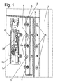
- the reference numeral 1 denotes in each case a side wall of a cabinet, not specified, on which by means of an adapter 2, a cabinet suspension device 3 can be fixed.
- the cupboard hanging device 3 corresponds in its construction in the one DE 201 03 728 UI illustrated and described cupboard hanging device.
- the cabinet suspension device 3 is equipped with at least two support parts 3a in the form of turn-in dowels or the like. The longitudinal axes of these supporting parts 3a are perpendicular to the side wall. 1
- a plurality of dowels 4 for example, so-called adhesive anchors are introduced, in each of the adapter 2 by passing fastening screws 5 are screwed.
- fastening screws 5 so the adapter 2 can be screwed to achieve a large load capacity on the side wall 1 of a cabinet.
- the high carrying capacity is achieved despite the low load capacity of a lightweight panel or achieved by the dowels 4, preferably made of adhesive dowels according to the DE 20 2005 005 579 U1 consist.
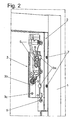
- the adapter 2 is in the embodiment, as it is in FIG. 1 and 2 is shown, strip-shaped and is what FIG. 1 particularly clearly shows, equipped with a number of shots, in which the support members 3a in the form of Einschlagdübeln or the like can be introduced.
- the receiving bushes 6 can be provided in the direction of their longitudinal axis with a slot 6a and thus be equipped with a certain spring elasticity, so that tolerances between the bore diameter of the receiving socket 6 on the one hand and the knock-in plugs 3a on the other hand can be very well compensated.
- the support members 3 a introduced into the receiving sockets 6 can be secured by clamping screws 7 acting radially on the said supporting members 3 a.
- the cabinet suspension device 3 which is provided with a base plate 3b, in addition to fixing on the adapter 2 can also be fixed to a rear wall of a cabinet, not shown, and has for this purpose a base plate 3b passing through hole 3c, through which a screw in a rear wall a cabinet can be screwed. As a result, the entire cabinet suspension device can not change its position even under load.
- the adapter 2 can additionally be screwed to a rear wall, not shown, this would require additional, perpendicular to the rear wall bores in the adapter 2 may be introduced to introduce appropriate connection screws and screw into the rear wall.
- FIG. 3 makes particularly vivid, angle-shaped, with a leg 2a rests on the side wall 1 and the other leg 2b on the rear wall of a cabinet, not shown.
- dowels 4 again so-called adhesive bucket, as they are from the DE 20 2005 005 579 U1 are known.
- adhesive bucket as they are from the DE 20 2005 005 579 U1 are known.
- These dowels are particularly suitable for lightweight panels in which a honeycomb structure, for example made of cardboard, is arranged between two cover plates.
- the base plate 3a of the cabinet suspension device 3 is in the embodiment according to the Figures 3 and 4 with its back on the leg 2b of the adapter 2.
- the parallel to the side wall 1 extending and resting on this leg 2a of the adapter 2 is again equipped with receiving sockets 6 for the supporting parts 3a of the cabinet suspension device 3.
- the receiving sockets 6 in the embodiment of the Figures 3 and 4 the form of open pods Similarly, the receiving sockets 6 cup-shaped and thus formed closed at the front end.
- cupboard hanging device can be connected by screws 8 with the leg 2b of the adapter 2.
- connection arrangement according to the invention offers the advantage that a cupboard hanging device 3 which is known per se and can also be used otherwise can also be securely fixed to a side wall 1 of a cupboard which does not have the required load-bearing capacity.
- This carrying capacity is ensured by the connection arrangement according to the invention as well as the possibility to be able to easily maintain the special connection of the cabinet suspension device on supporting parts in the form of Einschlagdübeln.
- the respective adapter 2 of a connection arrangement according to the invention is made of metal, wherein in the case of a strip-shaped adapter, as in the FIGS. 1 and 2 represented, quite an embodiment of a correspondingly viable plastic comes into consideration.
Landscapes
- Connection Of Plates (AREA)
- Furniture Connections (AREA)
Description
- Die vorliegende Erfindung betrifft eine Verbindungsanordnung zum Verbinden einer mit Tragteilen in Form von Einschlagdübeln oder dergleichen versehenen Schrankaufhängevorrichtung an einer aus einer Leichtbauplatte bestehenden Seitenwand eines Schrankes.
- Eine Schrankaufhängevorrichtung mit Tragteilen in Form von Einschlagdübeln ist aus der
DE 201 03 728 U1 bekannt. Eine weitere Schrankaufhängevorrichtung ist aus derEP 0 389 054 A2 bekannt. - Eine derartige Schrankaufhängevorrichtung ist problemlos dann an einer Seitenwand eines Schrankes befestigbar, wenn diese Seitenwand aus relativ hochwertigem und tragfestem Platten - Material besteht.
- In der Möbelindustrie werden sowohl aus Kostengründen wie auch aus Gründen einer Gewichtsersparnis zunehmend Platten verwendet, bei denen eine sichere Befestigung einer Schrankaufhängevorrichtung mit Tragteilen in Form von Einschlagdübeln aufgrund der zu geringen Tragfähigkeit nicht möglich ist.
- Der vorliegenden Erfindung liegt die Aufgabe zugrunde, eine Verbindungsanordnung der gattungsgemäßen Art zu schaffen, bei der trotz Verwendung sogenannter "Leichtbau-Platten" und ohne Veränderung der Schrankaufhängevorrichtung eine hoch belastbare Verbindung zwischen einem Schrank einerseits und der Schrankaufhängevorrichtung andererseits erzielt werden kann.
- Diese Aufgabe wird erfindungsgemäß gelöst durch einen Adapter, welcher mittels zweier oder mehrerer Schrauben, die in einer entsprechende Anzahl von in einer Seitenwand festgelegten Dübeln einschraubbar sind, an einer Seitenwand eines Schrankes festlegbar und mit einer der Anzahl der Tragkörper der Schrankaufhängevorrichtung entsprechenden Zahl von Aufnahmebuchsen für die Tragteile ausgestattet ist.
- Durch diesen Adapter wird eine hoch belastbare und sichere Verbindung zwischen einer bekannten und auch anderweitig verwendbaren Schrankaufhängevorrichtung einerseits und einem aus beispielsweise Leichtbau-Platten hergestellten Schrank-Möbel andererseits möglich. Der Adapter wird fest an einer Seitenwand eines Schrankes angeschraubt, wozu die dort eingesetzten Dübel zuvor in diese Seitenwand eingesetzt sind.
- Durch die Dübel wird eine hoch belastbare Verbindung zwischen dem Adapter und der Seitenwand hergestellt. Damit kann der Adapter nun mit entsprechender Tragfähigkeit die Schrankaufhängevorrichtung aufnehmen, wobei die Montage der Schrankaufhängevorrichtung gegenüber dem Adapter durch einfaches Eintreiben der Tragkörper in die Aufnahmebuchsen des Adapters erfolgt.
- Weitere Merkmale der Erfindung sind Gegenstand von Unteransprüchen.
- In den beigefügten Zeichnungen sind Ausführungsbeispiele der Erfindung dargestellt, die im folgenden näher beschrieben werden.
- Im Einzelnen zeigen
-
Figur 1 eine perspektivische Sprengbild-Darstellung einer erfindungsgemäßen Verbindungsanordnung, -
Figur 2 eine Perspektivdarstellung der Verbindungsanordnung im montierten Zustand, -
Figur 3 eine perspektivische Sprengbild-Darstellung einer Verbindungsanordnung nach einem weiteren Ausführungsbeispiel der Erfindung, -
Figur 4 eine perspektivische Darstellung der Verbindungsanordnung gemäßFigur 3 im montierten Zustand. - In den Zeichnungen ist mit dem Bezugszeichen 1 jeweils eine Seitenwand eines nicht näher bezeichneten Schrankes bezeichnet, an dem mittels eines Adapters 2 eine Schrankaufhängevorrichtung 3 festlegbar ist.
- Die Schrankaufhängevorrichtung 3 entspricht in ihrem Aufbau einer in der
DE 201 03 728 UI dargestellten und beschriebenen Schrankaufhängevorrichtung. Im Zusammenhang mit der vorliegenden Erfindung ist hier von Bedeutung, dass die Schrankaufhängevorrichtung 3 mit mindestens zwei Tragteilen 3a in Form von Einschlagdübeln oder dergleichen ausgestattet ist. Die Längsachsen dieser Tragteile 3a verlaufen lotrecht zur Seitenwand 1. - In die aus einer Leichtbau-Platte bestehende Seitenwand 1 sind mehrere Dübel 4, beispielsweise sogenannte Klebedübel eingebracht, in die jeweils den Adapter 2 durchtretende Befestigungsschrauben 5 einschraubbar sind. Durch die Befestigungsschrauben 5 kann also der Adapter 2 unter Erzielung einer großen Tragfähigkeit an der Seitenwand 1 eines Schrankes angeschraubt werden. Dabei wird die hohe Tragfähigkeit trotz der an sich geringen Belastbarkeit einer Leichtbau-Platte erzielt oder erreicht durch die Dübel 4, die vorzugsweise aus Klebedübeln gemäß der
DE 20 2005 005 579 U1 bestehen. - Der Adapter 2 ist im Ausführungsbeispiel, wie es in
Figur 1 und2 gezeigt ist, leistenförmig ausgebildet und ist, wasFigur 1 besonders anschaulich zeigt, mit mehreren Aufnahmen ausgestattet, in welche die Tragteile 3a in Form von Einschlagdübeln oder dergleichen einbringbar sind. Dabei können die Aufnahmebuchsen 6 in Richtung ihrer Längsachse mit einem Schlitz 6a versehen und somit mit einer gewissen Federelastizität ausgestattet sein, so dass Toleranzen zwischen dem Bohrungsdurchmesser der Aufnahmebuchsen 6 einerseits und den Einschlagdübeln 3a andererseits sehr gut ausgeglichen werden können. - Zusätzlich können die in die Aufnahmebuchsen 6 eingebrachten Tragteile 3a durch radial auf die besagten Tragteile 3a einwirkende Klemmschrauben 7 gesichert werden.
- Die Schrankaufhängevorrichtung 3, welche mit einer Grundplatte 3b versehen ist, kann zusätzlich zur Festlegung am Adapter 2 auch an einer nicht dargestellten Rückwand eines Schrankes fixiert werden und weist zu diesem Zweck eine die Grundplatte 3b durchtretende Bohrung 3c auf, durch welche eine Schraube in eine Rückwand eines Schrankes eingeschraubt werden kann. Dadurch kann die gesamte Schrankaufhängevorrichtung auch unter Belastung ihre Position nicht verändern.
- Zur Erhöhung der Gesamtstabilität der dargestellten und beschriebenen Verbindungsanordnung kann zusätzlich der Adapter 2 mit einer nicht dargestellten Rückwand verschraubt werden, hierzu müssten zusätzliche, lotrecht zur Rückwand verlaufende Bohrungen in den Adapter 2 eingebracht sein, um entsprechende Verbindungsschrauben einbringen und in die Rückwand schrauben zu können.
- Beim Ausführungsbeispiel der Erfindung gemäß den
Figuren 3 und4 ist der Adapter 2, wasFigur 3 besonders anschaulich macht, winkelförmig ausgebildet, wobei ein Schenkel 2a auf der Seitenwand 1 und der andere Schenkel 2b auf der nicht dargestellten Rückwand eines Schrankes aufliegt. - Der auf der Seitenwand 1 aufliegende Schenkel 2a des Adapters 2 ist wiederum mit Durchgangsbohrungen für Befestigungsschrauben 5 versehen, welche in die Dübel 4 innerhalb der Seitenwand 1 einschraubbar sind.
- Auch hier kann es sich bei den Dübeln 4 wiederum um sogenannte Klebedübel handeln, wie sie aus der
DE 20 2005 005 579 U1 bekannt sind. Diese Dübel sind besonders für solche Leichtbau-Platten geeignet, bei denen zwischen zwei Deckplatten eine Wabenstruktur, beispielsweise aus Karton, angeordnet ist. - Die Grundplatte 3a der Schrankaufhängevorrichtung 3 liegt beim Ausführungsbeispiel gemäß den
Figuren 3 und4 mit ihrer Rückseite auf dem Schenkel 2b des Adapters 2 auf. Der parallel zur Seitenwand 1 verlaufende und auf dieser aufliegende Schenkel 2a des Adapters 2 ist wieder mit Aufnahmebuchsen 6 für die Tragteile 3a der Schrankaufhängevorrichtung 3 ausgestattet. Dabei können die Aufnahmebuchsen 6 im Ausführungsbeispiel nach denFiguren 3 und4 die Form von offenen Hülsen aufweisen, ebenso können die Aufnahmebuchsen 6 topfförmig und somit am stimseitigen Ende geschlossen ausgebildet sein. - Bei Bedarf kann zur Stabilisierung der gesamten Verbindungsanordnung die auf dem Schenkel 2b aufliegende Schrankaufhängevorrichtung durch Schrauben 8 mit dem Schenkel 2b des Adapters 2 verbunden sein.
- Demzufolge kann eine Verbindung der Schrankaufhängevorrichtung 3 mit einer Rückwand eines Schrankes entfallen.
- Die erfindungsgemäße Verbindungsanordnung bietet insgesamt den Vorteil, dass eine an sich bekannte und auch anderweitig verwendbare Schrankaufhängevorrichtung 3 auch sicher an einer Seitenwand 1 eines Schrankes festlegbar ist, die von Haus aus nicht die dafür erforderliche Tragfähigkeit aufweist. Diese Tragfähigkeit wird durch die erfindungsgemäße Verbindungsanordnung ebenso gewährleistet wie die Möglichkeit, die spezielle Anbindung der Schrankaufhängevorrichtung über Tragteile in Form von Einschlagdübeln problemlos beibehalten zu können.
- Vorzugsweise ist der jeweilige Adapter 2 einer erfindungsgemäßen Verbindungsanordnung aus Metall hergestellt, wobei im Falle eines leistenförmigen Adapters, wie in den
Figuren 1 und2 dargestellt, durchaus auch eine Ausführung aus einem entsprechend tragfähigen Kunststoff in Betracht kommt.
Claims (11)
- Verbindungsanordnung zum Verbinden einer mit Tragteilen (3a) in Form von Einschlagdübeln oder dergleichen versehenen Schrankaufhängevorrichtung (3) an einer aus einer Leichtbauplatte bestehenden Seitenwand (1) eines Schrankes, gekennzeichnet durch einen Adapter (2), welcher mittels zweier oder mehrerer Schrauben (5), die in eine entsprechende Anzahl von in einer Seitenwand (1) festgelegten Dübeln (4) einschraubbar sind, an einer Seitenwand eines Schrankes festlegbar und mit einer der Anzahl der Tragteile (3a) der Schrankaufhängevorrichtung (3) entsprechenden Zahl von Aufnahmebuchsen (6) für die Tragteile (3a) ausgestattet ist.
- Verbindungsanordnung nach Anspruch 1, dadurch gekennzeichnet, dass der Adapter (2) leistenförmig ausgebildet ist.
- Verbindungsanordnung nach Anspruch 1, dadurch gekennzeichnet, dass der Adapter (2) winkelförmig ausgebildet ist.
- Verbindungsanordnung nach einem der vorhergehenden Ansprüche, dadurch gekennzeichnet, dass die Aufnahmebuchsen (6) in Form von Bohrungen ausgeführt sind.
- Verbindungsanordnung nach Anspruch 4, dadurch gekennzeichnet, dass die Bohrungen in Richtung der Längsachsen mit einem Schlitz (6a) ausgestattet sind.
- Verbindungsanordnung nach einem der Ansprüche 1 bis 3, dadurch gekennzeichnet, dass die Aufnahmebuchsen (6) als ausgeprägte Hülsen ausgebildet sind.
- Verbindungsanordnung nach Anspruch 6, dadurch gekennzeichnet, dass die die Aufnahmebuchsen (6) bildenden Hülsen stirnseitig geschlossen und insoweit als Topfhülsen ausgebildet sind.
- Verbindungsanordnung nach einem der vorhergehenden Ansprüche, dadurch gekennzeichnet, dass der Adapter (2) einstückig aus Metall hergestellt ist.
- Verbindungsanordnung nach einem der vorhergehenden Ansprüche, dadurch gekennzeichnet, dass der Adapter (2) mit einer Grundplatte (3b) der Aufhängungsvorrichtung (3) verbunden ist.
- Verbindungsanordnung nach einem der Ansprüche 1 bis 8, dadurch gekennzeichnet, dass der Adapter (2) mit einer Rückwand eines Schrankes verbindbar ist.
- Verbindungsanordnung nach einem der vorhergehenden Ansprüche, dadurch gekennzeichnet, dass die in die Aufnahmebuchsen (6) eingreifenden Tragteile (3a) durch radial auf die Tragteile auftreffende Klemmschrauben (7) fixiert sind.
Applications Claiming Priority (2)
| Application Number | Priority Date | Filing Date | Title |
|---|---|---|---|
| DE202007006527U DE202007006527U1 (de) | 2007-05-04 | 2007-05-04 | Verbindungsanordnung |
| PCT/EP2008/055153 WO2008135424A1 (de) | 2007-05-04 | 2008-04-28 | Verbindungsanordnung |
Publications (2)
| Publication Number | Publication Date |
|---|---|
| EP2152122A1 EP2152122A1 (de) | 2010-02-17 |
| EP2152122B1 true EP2152122B1 (de) | 2013-06-12 |
Family
ID=39579976
Family Applications (1)
| Application Number | Title | Priority Date | Filing Date |
|---|---|---|---|
| EP08749781.4A Not-in-force EP2152122B1 (de) | 2007-05-04 | 2008-04-28 | Verbindungsanordnung |
Country Status (3)
| Country | Link |
|---|---|
| EP (1) | EP2152122B1 (de) |
| DE (1) | DE202007006527U1 (de) |
| WO (1) | WO2008135424A1 (de) |
Families Citing this family (4)
| Publication number | Priority date | Publication date | Assignee | Title |
|---|---|---|---|---|
| IT1391746B1 (it) * | 2008-07-29 | 2012-01-27 | Leonardo Srl | Gruppo reggipensile regolabile per l'ancoraggio a parete di un mobile pensile, con mezzi perfezionati di fissaggio alla spalla del mobile pensile |
| DE202008015704U1 (de) * | 2008-11-27 | 2010-04-15 | Hettich-Heinze Gmbh & Co. Kg | Schrankaufhänger für Möbel aus Leichtbauplatten |
| ES2395814B1 (es) * | 2011-06-30 | 2013-07-15 | Miguel Angel Rioja Calvo | Soporte inferior para muebles en pared |
| IT201700110599A1 (it) * | 2017-10-03 | 2019-04-03 | Leonardo Srl | Gruppo reggipensile nascosto resistente allo strappo e con regolazione in profondita’ precisa |
Family Cites Families (7)
| Publication number | Priority date | Publication date | Assignee | Title |
|---|---|---|---|---|
| ES2074523T3 (es) * | 1989-03-20 | 1995-09-16 | Camar Spa | Dispositivo oculto para montar en pared un elemento mobiliario de pared. |
| DE9201572U1 (de) * | 1992-02-08 | 1993-03-18 | Paul Hettich GmbH & Co, 4983 Kirchlengern | Aufhängevorrichtung für Möbel |
| AT402596B (de) * | 1994-08-26 | 1997-06-25 | Blum Gmbh Julius | Möbelbeschlag, insbesondere verbindungsbeschlag möbelbeschlag, insbesondere verbindungsbeschlag |
| DE20103728U1 (de) | 2001-03-03 | 2001-05-03 | Paul Hettich Gmbh & Co., 32278 Kirchlengern | Schrankaufhängevorrichtung |
| ITMI20022147A1 (it) * | 2002-10-10 | 2004-04-11 | Leonardo Srl | Reggipensile nascosto regolabile con sistema di fissaggio perfezionato alla spalla di un moble pensile. |
| DE20219074U1 (de) * | 2002-12-10 | 2003-05-08 | Bossow, Ralf, 46487 Wesel | Aufhängeradaptergrundplatte |
| DE202005005579U1 (de) | 2005-04-07 | 2006-08-17 | Hettich-Heinze Gmbh & Co. Kg | Verbindungseinsatz |
-
2007
- 2007-05-04 DE DE202007006527U patent/DE202007006527U1/de not_active Expired - Lifetime
-
2008
- 2008-04-28 EP EP08749781.4A patent/EP2152122B1/de not_active Not-in-force
- 2008-04-28 WO PCT/EP2008/055153 patent/WO2008135424A1/de not_active Ceased
Also Published As
| Publication number | Publication date |
|---|---|
| DE202007006527U1 (de) | 2008-09-18 |
| WO2008135424A1 (de) | 2008-11-13 |
| EP2152122A1 (de) | 2010-02-17 |
Similar Documents
| Publication | Publication Date | Title |
|---|---|---|
| EP3114359B1 (de) | Vorrichtung zur verbindung eines strukturelements mit einem halteelement in einem abstand zueinander | |
| DE9113038U1 (de) | Aufhängungssystem für Gemälderahmen o.dgl. | |
| DE8520800U1 (de) | Plattenhalter | |
| DE202008002540U1 (de) | Beschlag zum Festlegen einer Leichtbauplatte | |
| DE102017108523A1 (de) | Montageplattenanordnung für einen Schaltschrank | |
| DE102017109612A1 (de) | Trennwand | |
| EP2152122A1 (de) | Verbindungsanordnung | |
| DE20210049U1 (de) | Bandaufnahmeelement für Block- und Futterzargen | |
| DE202022104613U1 (de) | Eckverbinder | |
| DE3820334C1 (en) | Arrangement for mounting a sun visor in a vehicle | |
| DE102014115091A1 (de) | Klemmhalterung | |
| DE102011081917B4 (de) | Dämpfung für Hausgerätetüren | |
| DE8021658U1 (de) | Möbelbeschlag für die Befestigung einer Frontplatte | |
| DE102014216485A1 (de) | Bodenmodul für ein Haushaltsgerät | |
| DE102006004176A1 (de) | Tischsystem | |
| DE29701469U1 (de) | Verbindungselement aus Kunststoff | |
| DE102010024341A1 (de) | Verbindungsvorrichtung und Verteilerschrank-Anordnung | |
| DE202014106211U1 (de) | Kreuzgelenk mit abgefederten Zylinderstiften | |
| DE10206756B4 (de) | Schalt-Federkontaktstift | |
| WO1998044234A1 (de) | Klemmbeschlag für die befestigung von glasscheiben | |
| DE102011085456A1 (de) | Adapter zum Anbinden einer Frontblende an eine Seitenzarge eines Möbelteils sowie Möbelteil mit einem solchen Adapter | |
| EP3227863B1 (de) | Kraftfahrzeugschlüssel | |
| EP1728452A1 (de) | Verbindungselement zum Herstellen von Möbelstücken | |
| DE3509066C1 (de) | Chassishalteteil für Fernsehgeräte | |
| DE202008008058U1 (de) | Staudenhalter |
Legal Events
| Date | Code | Title | Description |
|---|---|---|---|
| PUAI | Public reference made under article 153(3) epc to a published international application that has entered the european phase |
Free format text: ORIGINAL CODE: 0009012 |
|
| 17P | Request for examination filed |
Effective date: 20091023 |
|
| AK | Designated contracting states |
Kind code of ref document: A1 Designated state(s): AT BE BG CH CY CZ DE DK EE ES FI FR GB GR HR HU IE IS IT LI LT LU LV MC MT NL NO PL PT RO SE SI SK TR |
|
| AX | Request for extension of the european patent |
Extension state: AL BA MK RS |
|
| DAX | Request for extension of the european patent (deleted) | ||
| 17Q | First examination report despatched |
Effective date: 20101209 |
|
| GRAP | Despatch of communication of intention to grant a patent |
Free format text: ORIGINAL CODE: EPIDOSNIGR1 |
|
| GRAS | Grant fee paid |
Free format text: ORIGINAL CODE: EPIDOSNIGR3 |
|
| GRAA | (expected) grant |
Free format text: ORIGINAL CODE: 0009210 |
|
| AK | Designated contracting states |
Kind code of ref document: B1 Designated state(s): AT BE BG CH CY CZ DE DK EE ES FI FR GB GR HR HU IE IS IT LI LT LU LV MC MT NL NO PL PT RO SE SI SK TR |
|
| REG | Reference to a national code |
Ref country code: GB Ref legal event code: FG4D Free format text: NOT ENGLISH |
|
| REG | Reference to a national code |
Ref country code: CH Ref legal event code: EP |
|
| REG | Reference to a national code |
Ref country code: AT Ref legal event code: REF Ref document number: 616333 Country of ref document: AT Kind code of ref document: T Effective date: 20130615 |
|
| REG | Reference to a national code |
Ref country code: IE Ref legal event code: FG4D Free format text: LANGUAGE OF EP DOCUMENT: GERMAN |
|
| REG | Reference to a national code |
Ref country code: DE Ref legal event code: R096 Ref document number: 502008010116 Country of ref document: DE Effective date: 20130801 |
|
| PG25 | Lapsed in a contracting state [announced via postgrant information from national office to epo] |
Ref country code: LT Free format text: LAPSE BECAUSE OF FAILURE TO SUBMIT A TRANSLATION OF THE DESCRIPTION OR TO PAY THE FEE WITHIN THE PRESCRIBED TIME-LIMIT Effective date: 20130612 Ref country code: GR Free format text: LAPSE BECAUSE OF FAILURE TO SUBMIT A TRANSLATION OF THE DESCRIPTION OR TO PAY THE FEE WITHIN THE PRESCRIBED TIME-LIMIT Effective date: 20130913 Ref country code: SI Free format text: LAPSE BECAUSE OF FAILURE TO SUBMIT A TRANSLATION OF THE DESCRIPTION OR TO PAY THE FEE WITHIN THE PRESCRIBED TIME-LIMIT Effective date: 20130612 Ref country code: SE Free format text: LAPSE BECAUSE OF FAILURE TO SUBMIT A TRANSLATION OF THE DESCRIPTION OR TO PAY THE FEE WITHIN THE PRESCRIBED TIME-LIMIT Effective date: 20130612 Ref country code: ES Free format text: LAPSE BECAUSE OF FAILURE TO SUBMIT A TRANSLATION OF THE DESCRIPTION OR TO PAY THE FEE WITHIN THE PRESCRIBED TIME-LIMIT Effective date: 20130923 Ref country code: NO Free format text: LAPSE BECAUSE OF FAILURE TO SUBMIT A TRANSLATION OF THE DESCRIPTION OR TO PAY THE FEE WITHIN THE PRESCRIBED TIME-LIMIT Effective date: 20130912 Ref country code: FI Free format text: LAPSE BECAUSE OF FAILURE TO SUBMIT A TRANSLATION OF THE DESCRIPTION OR TO PAY THE FEE WITHIN THE PRESCRIBED TIME-LIMIT Effective date: 20130612 |
|
| REG | Reference to a national code |
Ref country code: NL Ref legal event code: VDEP Effective date: 20130612 |
|
| REG | Reference to a national code |
Ref country code: LT Ref legal event code: MG4D |
|
| PG25 | Lapsed in a contracting state [announced via postgrant information from national office to epo] |
Ref country code: BG Free format text: LAPSE BECAUSE OF FAILURE TO SUBMIT A TRANSLATION OF THE DESCRIPTION OR TO PAY THE FEE WITHIN THE PRESCRIBED TIME-LIMIT Effective date: 20130912 Ref country code: HR Free format text: LAPSE BECAUSE OF FAILURE TO SUBMIT A TRANSLATION OF THE DESCRIPTION OR TO PAY THE FEE WITHIN THE PRESCRIBED TIME-LIMIT Effective date: 20130612 |
|
| PG25 | Lapsed in a contracting state [announced via postgrant information from national office to epo] |
Ref country code: LV Free format text: LAPSE BECAUSE OF FAILURE TO SUBMIT A TRANSLATION OF THE DESCRIPTION OR TO PAY THE FEE WITHIN THE PRESCRIBED TIME-LIMIT Effective date: 20130612 |
|
| PG25 | Lapsed in a contracting state [announced via postgrant information from national office to epo] |
Ref country code: CZ Free format text: LAPSE BECAUSE OF FAILURE TO SUBMIT A TRANSLATION OF THE DESCRIPTION OR TO PAY THE FEE WITHIN THE PRESCRIBED TIME-LIMIT Effective date: 20130612 Ref country code: IS Free format text: LAPSE BECAUSE OF FAILURE TO SUBMIT A TRANSLATION OF THE DESCRIPTION OR TO PAY THE FEE WITHIN THE PRESCRIBED TIME-LIMIT Effective date: 20131012 Ref country code: EE Free format text: LAPSE BECAUSE OF FAILURE TO SUBMIT A TRANSLATION OF THE DESCRIPTION OR TO PAY THE FEE WITHIN THE PRESCRIBED TIME-LIMIT Effective date: 20130612 Ref country code: SK Free format text: LAPSE BECAUSE OF FAILURE TO SUBMIT A TRANSLATION OF THE DESCRIPTION OR TO PAY THE FEE WITHIN THE PRESCRIBED TIME-LIMIT Effective date: 20130612 Ref country code: PT Free format text: LAPSE BECAUSE OF FAILURE TO SUBMIT A TRANSLATION OF THE DESCRIPTION OR TO PAY THE FEE WITHIN THE PRESCRIBED TIME-LIMIT Effective date: 20131014 |
|
| PG25 | Lapsed in a contracting state [announced via postgrant information from national office to epo] |
Ref country code: RO Free format text: LAPSE BECAUSE OF FAILURE TO SUBMIT A TRANSLATION OF THE DESCRIPTION OR TO PAY THE FEE WITHIN THE PRESCRIBED TIME-LIMIT Effective date: 20130612 Ref country code: NL Free format text: LAPSE BECAUSE OF FAILURE TO SUBMIT A TRANSLATION OF THE DESCRIPTION OR TO PAY THE FEE WITHIN THE PRESCRIBED TIME-LIMIT Effective date: 20130612 Ref country code: PL Free format text: LAPSE BECAUSE OF FAILURE TO SUBMIT A TRANSLATION OF THE DESCRIPTION OR TO PAY THE FEE WITHIN THE PRESCRIBED TIME-LIMIT Effective date: 20130612 |
|
| PLBE | No opposition filed within time limit |
Free format text: ORIGINAL CODE: 0009261 |
|
| STAA | Information on the status of an ep patent application or granted ep patent |
Free format text: STATUS: NO OPPOSITION FILED WITHIN TIME LIMIT |
|
| PG25 | Lapsed in a contracting state [announced via postgrant information from national office to epo] |
Ref country code: DK Free format text: LAPSE BECAUSE OF FAILURE TO SUBMIT A TRANSLATION OF THE DESCRIPTION OR TO PAY THE FEE WITHIN THE PRESCRIBED TIME-LIMIT Effective date: 20130612 |
|
| 26N | No opposition filed |
Effective date: 20140313 |
|
| PG25 | Lapsed in a contracting state [announced via postgrant information from national office to epo] |
Ref country code: IT Free format text: LAPSE BECAUSE OF FAILURE TO SUBMIT A TRANSLATION OF THE DESCRIPTION OR TO PAY THE FEE WITHIN THE PRESCRIBED TIME-LIMIT Effective date: 20130612 |
|
| REG | Reference to a national code |
Ref country code: DE Ref legal event code: R097 Ref document number: 502008010116 Country of ref document: DE Effective date: 20140313 |
|
| PG25 | Lapsed in a contracting state [announced via postgrant information from national office to epo] |
Ref country code: MC Free format text: LAPSE BECAUSE OF FAILURE TO SUBMIT A TRANSLATION OF THE DESCRIPTION OR TO PAY THE FEE WITHIN THE PRESCRIBED TIME-LIMIT Effective date: 20130612 Ref country code: LU Free format text: LAPSE BECAUSE OF FAILURE TO SUBMIT A TRANSLATION OF THE DESCRIPTION OR TO PAY THE FEE WITHIN THE PRESCRIBED TIME-LIMIT Effective date: 20140428 |
|
| REG | Reference to a national code |
Ref country code: CH Ref legal event code: PL |
|
| GBPC | Gb: european patent ceased through non-payment of renewal fee |
Effective date: 20140428 |
|
| REG | Reference to a national code |
Ref country code: FR Ref legal event code: ST Effective date: 20141231 |
|
| REG | Reference to a national code |
Ref country code: IE Ref legal event code: MM4A |
|
| PG25 | Lapsed in a contracting state [announced via postgrant information from national office to epo] |
Ref country code: CH Free format text: LAPSE BECAUSE OF NON-PAYMENT OF DUE FEES Effective date: 20140430 Ref country code: LI Free format text: LAPSE BECAUSE OF NON-PAYMENT OF DUE FEES Effective date: 20140430 Ref country code: GB Free format text: LAPSE BECAUSE OF NON-PAYMENT OF DUE FEES Effective date: 20140428 |
|
| PG25 | Lapsed in a contracting state [announced via postgrant information from national office to epo] |
Ref country code: FR Free format text: LAPSE BECAUSE OF NON-PAYMENT OF DUE FEES Effective date: 20140430 |
|
| PG25 | Lapsed in a contracting state [announced via postgrant information from national office to epo] |
Ref country code: IE Free format text: LAPSE BECAUSE OF NON-PAYMENT OF DUE FEES Effective date: 20140428 |
|
| REG | Reference to a national code |
Ref country code: AT Ref legal event code: MM01 Ref document number: 616333 Country of ref document: AT Kind code of ref document: T Effective date: 20140428 |
|
| PGFP | Annual fee paid to national office [announced via postgrant information from national office to epo] |
Ref country code: DE Payment date: 20150422 Year of fee payment: 8 |
|
| PG25 | Lapsed in a contracting state [announced via postgrant information from national office to epo] |
Ref country code: AT Free format text: LAPSE BECAUSE OF NON-PAYMENT OF DUE FEES Effective date: 20140428 |
|
| PG25 | Lapsed in a contracting state [announced via postgrant information from national office to epo] |
Ref country code: MT Free format text: LAPSE BECAUSE OF FAILURE TO SUBMIT A TRANSLATION OF THE DESCRIPTION OR TO PAY THE FEE WITHIN THE PRESCRIBED TIME-LIMIT Effective date: 20130612 |
|
| PG25 | Lapsed in a contracting state [announced via postgrant information from national office to epo] |
Ref country code: CY Free format text: LAPSE BECAUSE OF FAILURE TO SUBMIT A TRANSLATION OF THE DESCRIPTION OR TO PAY THE FEE WITHIN THE PRESCRIBED TIME-LIMIT Effective date: 20130612 |
|
| PG25 | Lapsed in a contracting state [announced via postgrant information from national office to epo] |
Ref country code: BE Free format text: LAPSE BECAUSE OF FAILURE TO SUBMIT A TRANSLATION OF THE DESCRIPTION OR TO PAY THE FEE WITHIN THE PRESCRIBED TIME-LIMIT Effective date: 20140430 Ref country code: TR Free format text: LAPSE BECAUSE OF FAILURE TO SUBMIT A TRANSLATION OF THE DESCRIPTION OR TO PAY THE FEE WITHIN THE PRESCRIBED TIME-LIMIT Effective date: 20130612 Ref country code: HU Free format text: LAPSE BECAUSE OF FAILURE TO SUBMIT A TRANSLATION OF THE DESCRIPTION OR TO PAY THE FEE WITHIN THE PRESCRIBED TIME-LIMIT; INVALID AB INITIO Effective date: 20080428 |
|
| REG | Reference to a national code |
Ref country code: DE Ref legal event code: R119 Ref document number: 502008010116 Country of ref document: DE |
|
| PG25 | Lapsed in a contracting state [announced via postgrant information from national office to epo] |
Ref country code: DE Free format text: LAPSE BECAUSE OF NON-PAYMENT OF DUE FEES Effective date: 20161101 |