EP2151928A1 - Procédé de synchronisation rapide et de détection de séquences de saut de fréquence dans des réseaux de capteurs sans fil - Google Patents
Procédé de synchronisation rapide et de détection de séquences de saut de fréquence dans des réseaux de capteurs sans fil Download PDFInfo
- Publication number
- EP2151928A1 EP2151928A1 EP09167318A EP09167318A EP2151928A1 EP 2151928 A1 EP2151928 A1 EP 2151928A1 EP 09167318 A EP09167318 A EP 09167318A EP 09167318 A EP09167318 A EP 09167318A EP 2151928 A1 EP2151928 A1 EP 2151928A1
- Authority
- EP
- European Patent Office
- Prior art keywords
- frequency channels
- frequency
- synchronization information
- groups
- transmitted
- Prior art date
- Legal status (The legal status is an assumption and is not a legal conclusion. Google has not performed a legal analysis and makes no representation as to the accuracy of the status listed.)
- Granted
Links
- 238000000034 method Methods 0.000 title claims abstract description 42
- 238000001514 detection method Methods 0.000 title 1
- 238000005070 sampling Methods 0.000 claims abstract description 45
- 230000005540 biological transmission Effects 0.000 claims description 41
- 238000010586 diagram Methods 0.000 description 12
- 230000000694 effects Effects 0.000 description 11
- 230000015556 catabolic process Effects 0.000 description 6
- 230000001360 synchronised effect Effects 0.000 description 6
- 238000004891 communication Methods 0.000 description 5
- 230000008901 benefit Effects 0.000 description 3
- 230000008569 process Effects 0.000 description 3
- 235000008694 Humulus lupulus Nutrition 0.000 description 1
- 230000006978 adaptation Effects 0.000 description 1
- 230000008859 change Effects 0.000 description 1
- 125000004122 cyclic group Chemical group 0.000 description 1
- 230000002349 favourable effect Effects 0.000 description 1
- 230000007246 mechanism Effects 0.000 description 1
Images


Classifications
-
- H—ELECTRICITY
- H04—ELECTRIC COMMUNICATION TECHNIQUE
- H04B—TRANSMISSION
- H04B1/00—Details of transmission systems, not covered by a single one of groups H04B3/00 - H04B13/00; Details of transmission systems not characterised by the medium used for transmission
- H04B1/69—Spread spectrum techniques
- H04B1/713—Spread spectrum techniques using frequency hopping
- H04B1/7156—Arrangements for sequence synchronisation
- H04B2001/71563—Acquisition
-
- H—ELECTRICITY
- H04—ELECTRIC COMMUNICATION TECHNIQUE
- H04W—WIRELESS COMMUNICATION NETWORKS
- H04W72/00—Local resource management
- H04W72/04—Wireless resource allocation
- H04W72/044—Wireless resource allocation based on the type of the allocated resource
- H04W72/0453—Resources in frequency domain, e.g. a carrier in FDMA
Definitions
- the present invention relates to frequency hopping wireless systems, and, more particularly, to synchronization of frequency hopping wireless systems.
- any short-range wireless system that operates in frequency bands 902-928 MHz or 2400-2483.4 MHz should employ either frequency hopping methods or use digitally modulated techniques. Similar requirements are present in European standards (EN300-220) regarding the use of frequency band 863-870 MHz.
- the system divides the available frequency bandwidth into many frequency channels, and it continuously switches the channel, using a pseudorandom frequency hop sequence known to both the transmitter and the receiver.
- the FCC regulation for the 902 MHz band requires the system to use a minimum of fifty frequency channels.
- the nodes in the network follow a pseudorandom frequency hop pattern as the system switches between different frequency channels.
- the period during which the system stays in one frequency channel before hopping to the next channel is referred to as "dwell time".
- the FCC and EN300-220 regulations specify a maximum dwell time of 400 milliseconds.
- the dwell time can be fixed or it can change for different transmissions.
- each transmitter should, on average, use each channel in the frequency hop sequence equally.
- the FCC regulation specifies a maximum channel usage by the system: The average time of occupancy on any frequency channel should not be greater than 400 milliseconds within any window having a length of twenty seconds.
- both the sender and the receiver (and in general all the nodes in the system) are assumed to know the frequency hop sequence, in order to have a successful communication they should also be in synchronization in the sense that they should both know which position in the frequency hop sequence is being used at any moment in time.
- the system should provide a mechanism for the newly added nodes, or existing nodes that have lost the time-synchronization, to get in synchronization with the rest of the network and find the current frequency hop index in the frequency hop sequence.
- Synchronization latency is an important design factor. A newly added node should be able to get in synchronization with minimal delay to start the communication with the remainder of the network.
- the acceptable latencies for the synchronization process in many applications are on the order of one to two seconds.
- the present invention addresses the synchronization problem in frequency hopping systems.
- the invention provides a solution for synchronizing, in a time-efficient manner, a newly added node or an existing node that has lost time-synchronization with the rest of the network.
- the invention comprises, in one form thereof, a method of synchronizing wireless devices, including establishing a recurring sequence of frequency channels at which the wireless devices are to communicate.
- the frequency channels are divided into a plurality of groups. Synchronization information is transmitted at a respective first frequency channel in each of the groups of frequency channels during a first sampling time period. One of the groups of frequency channels is selected. A wireless device is used to sample each of the frequency channels in the selected group during the first sampling time period. Non-synchronization information is transmitted after the first sampling time period. Synchronization information is transmitted at a next respective frequency channel in each of the groups of frequency channels during a next sampling time period. The next sampling time period occurs after the transmitting of the non-synchronization information.
- the invention comprises, in another form thereof, a method of synchronizing wireless devices, including establishing a recurring sequence of frequency channels at which the wireless devices are to communicate.
- the frequency channels are divided into a plurality of groups.
- Synchronization information is transmitted at a respective first frequency channel in each of the groups of frequency channels during a first sampling time period.
- a wireless device is used to select one of the groups of frequency channels.
- the wireless device is used to sample each of the frequency channels in the selected group for the synchronization information. The sampling occurs during the first sampling time period.
- Non-synchronization information is transmitted after the first sampling time period.
- Synchronization information is transmitted at a next respective frequency channel in each of the groups of frequency channels during a next sampling time period.
- the next sampling time period occurs after the transmitting of the non-synchronization information.
- Non-synchronization information is transmitted after the next sampling period.
- the steps of transmitting synchronization information at a next respective frequency channel and transmitting the non-synchronization information are repeated until synchronization
- the invention comprises, in yet another form thereof, a method of synchronizing wireless devices, including informing each of the wireless devices of a frequency channel hop sequence at which non-synchronization information is to be transmitted. Synchronization information is sequentially transmitted to each of a plurality of frequency channels in a first subset of the frequency channels included in the hop sequence. A wireless device is used to sample each of the frequency channels in a second subset of the frequency channels. The second subset includes one frequency channel included in the first subset and at least one frequency channel omitted from the first subset. Non-synchronization information is transmitted after the sampling of the frequency channels in the second subset. Synchronization information is sequentially transmitted to each of a plurality of frequency channels in a third subset of the frequency channels. The third subset includes one of the frequency channels in the second subset and none of the frequency channels in the first subset.
- An advantage of the present invention is that both the synchronization latency and the transmission time on each frequency channel are reduced.
- Another advantage is that the present invention complies with all known government regulations for frequency channel usage.
- the present invention may be described herein in terms of algorithms and operations on data bits within a computer. It has proven convenient, primarily for reasons of common usage among those skilled in the art, to describe the invention in terms of algorithms and operations on data bits. It is to be understood, however, that these and similar terms are to be associated with appropriate physical elements, and are merely convenient labels applied to these physical elements. Unless otherwise stated herein, or apparent from the description, terms such as “calculating”, “determining”, “processing” or “computing”, or similar terms, refer the actions of a computing device that may perform these actions automatically, i.e., without human intervention, after being programmed to do so.
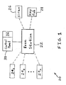
- Network 20 includes a base station, i.e., hub 22, a plurality of sensors 24 1 , 24 2 , ..., 24 n , a siren 26, a key fob 28 and a control panel 30 that may include a keypad 32.
- Control panel 30 may be hard wired to hub 22, while sensors 24 1-n , siren 26 and key fob 28 are in wireless communication with hub 22, as indicated by the dashed lines in FIG. 1 .
- Base station 22 and control panel 30 may be powered by household alternating current, and sensors 24 1 , 24 2 , ..., 24 n , siren 26 and key fob 28 may be battery powered.
- base station 22 is the gateway to control panel 30, which the user can use to interact with the system.
- network 20 is in the form of a wireless Local Security Network (wLSN) system which is a wireless intrusion and alarm system.
- wLSN wireless Local Security Network
- the network uses a frequency hop pattern. After each transmission, the network hops to the next channel in the hop sequence.
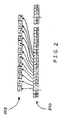
- FIG. 2 illustrates a frequency hop pattern or sequence 200 and associated transmission times 202.
- the hop sequence uses fifty-nine frequency channels. Note that, as is shown in FIG. 2 , the transmission time or "dwell time" (i.e., the period during which the system stays on one channel before moving to the next channel) can be different across different transmissions. However, it may be advantageous for each channel to be used for an equal amount of time, on average, in order to avoid any channel being used for more than 400 milliseconds within any 20 second window.
- FIG. 3 illustrates a frequency hop pattern or sequence 300 and associated transmission times 302 according to another embodiment.
- base station 22 may be used to wirelessly and periodically transmit "beacons" 304 (i.e., announcement messages) to inform all of the newly added nodes (or, more generally, nodes that need to get synchronized with the network) of the frequency hop sequence and the current hop position.
- "beacons" 304 i.e., announcement messages
- announcement packets may contain information about the hop pattern and the current frequency hop index.
- the announcement packets may contain the seed value of the random number generator which is used for creating the pseudorandom frequency hop pattern.
- the beacon transmissions need to comply with the government regulations, and therefore it may be advantageous for the beacon transmissions to be sent to all frequency channels used by the system.
- the beacons are generally not transmitted to only one fixed frequency channel or only one sub group of channels.
- the announcement packets (beacons) may themselves follow a frequency hop sequence and use each frequency channel equally.
- the beacon hop sequence can be the same as or different from the main frequency hop pattern used in the network. However, it is possible, according to the invention, for the beacon hop sequence to be different from the main frequency hop pattern used in the network in order to improve the synchronization latency.
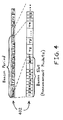
- the upper portion of FIG. 4 illustrates transmission times 402 associated with a frequency hop pattern in another embodiment.
- the lower portion of FIG. 4 illustrates transmission times 402 including an expanded illustration of the beacon slot.
- announcement packets are sent in all the frequency channels. Particularly, identical announcement packets may be sequentially sent to each of the fifty-nine frequency channels.
- a node that needs to get synchronized with the network may select one of the frequency channels randomly and listen to the channel for the announcement (beacon) message.
- an announcement packet is transmitted to the particular frequency channel that the node has selected and is listening to.
- the node receives the announcement message within the time duration of the beacon slot regardless of which of the frequency channels that the node selects.
- the synchronization latency may be determined by how often the system sends the beacons, i.e., the time period between time-adjacent transmissions of the beacon slots. This time period is labeled in FIG. 4 as the "beacon period.” In the worst case, the delay, or amount of time, required to achieve synchronization may be equal to one beacon period. On average, the delay, or amount of time required to achieve synchronization may be equal to one-half of a beacon period.
- a problem with the embodiment depicted in FIG. 4 is that many packets are transmitted within each beacon slot, which not only wastes the network time, but also uses the frequency channels inefficiently. Because of the inefficient use of the frequency channels, the amount of time remaining (out of the 400 milliseconds permitted by the government regulations to use each channel during a twenty second period) for other network operations becomes limited.
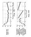
- FIG. 5 is a timing diagram illustrating the breakdown between synchronization time and time for other network activities within the transmission times in the embodiment of FIG. 4 , making some practical assumptions regarding the length of the announcement packet and the transmission times.
- the beacon transmission period may be no longer than one second. It may be assumed that within each announcement packet there are five bytes of data; seven bytes of overhead for the preamble, the start byte, and the switching of frequency channels; and two bytes for a cyclic redundancy check (CRC). These assumptions result in an overall announcement packet length of fourteen bytes. Assuming a data transmission rate of 9600 bits per second (which is typical for the radio used at the 900 MHz band), the transmission of a single announcement data packet to a single frequency channel requires twelve milliseconds.
- the transmission of a beacon slot may require fifty-nine data packet transmissions at twelve milliseconds per transmission, i.e., 708 milliseconds.
- the beacon slot may be transmitted once per second in order to achieve a worst-case delay of one second for synchronization.
- 708 milliseconds (70.8 % of the time) is occupied by beacon slot transmissions for synchronization, and the remaining 292 milliseconds (29.2 % of the time) is available for other network activities, as is illustrated in FIG. 5 .
- the next one-second beacon period, and the next beacon slot within the one-second beacon period may begin.
- each channel may be used (for any purpose, including synchronization and/or other network operations) for a maximum of 400 milliseconds.
- the transmission of announcement packets occupies each channel for twelve milliseconds in each one-second period, and so, in a twenty second period, each channel is used for 240 milliseconds (12 milliseconds/second x 20 seconds) by the beacon slots for the transmission of announcement packets. This leaves only 160 milliseconds (400 milliseconds - 240 milliseconds) for other network activities.
- Another embodiment of a synchronization method of the present invention has the advantages of achieving synchronization in less time and using the frequency channels more efficiently.
- the frequency channels are grouped, and longer but fewer announcement packets are transmitted. This may have the effect of reducing the transmission time of beacons and reducing the frequency channel usage.
- the frequency channels are divided into groups.
- the frequency channels are divided into groups of two for ease of illustration herein. After the simple case of groupings of two frequency channels is described, the generalized case of arbitrary groupings of arbitrary size will be described herein.
- all of the frequency channels (in this case, fifty-nine frequency channels) utilized by the network may be divided into groups of size two as follows:
- the base station does not need to send announcement packets in both channels in order for the node to receive the announcement packet.
- the base station transmits to one channel or the other in each group of two frequency channels. In a particular embodiment, in each beacon slot, the base station transmits in either the even-numbered channels or the odd-numbered channels.
- FIG. 7 is a comparison of the timing diagrams illustrating the breakdown between synchronization time and time for other network activities in the embodiments of FIGS. 6 and 7 .
- the base station transmits announcement packets to odd-numbered frequency channels in a first beacon slot, and to even-numbered frequency channels in a second beacon slot. This pattern may be repeated throughout the operation of the network, with the base station alternating between transmitting to odd-numbered frequency channels and transmitting to even-numbered frequency channels.
- the number of announcement packets transmitted in each beacon slot may be reduced.
- a step is taken to ensure that the receiving node does not miss receiving an announcement packet. Namely, the announcement packet is made to be of longer duration.
- the amount of time needed by the radio to switch to a new channel and sample the signal level may be about three to five milliseconds, as illustrated in FIG. 6 .
- the worst-case of five milliseconds may be assumed herein.
- the packet transmission time of an announcement packet may be increased by including a longer preamble in the transmission.
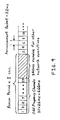
- the duration of the packet transmission may be set to be equal to or greater than the length of time between two samples of a same frequency channel. As illustrated in FIG. 8 , the length of time between two samples of frequency channel f1 is 10 milliseconds.
- an Added Preamble is provided having a same time length of 10 milliseconds.
- a preamble is added to the synchronization information wherein a time duration of the preamble is approximately equal to an amount of time needed to sample each of the frequency channels in the selected group.
- the length of time needed to transmit an announcement packet is 22 milliseconds (10 milliseconds + 12 milliseconds).
- thirty announcement packets are transmitted within each beacon slot, rather than fifty-nine, as in the embodiment of FIG. 5 .
- the overall length of the beacon slot is only 660 milliseconds (30 x 22 milliseconds), as shown in FIG. 9 , rather than the 708 millisecond overall length of the beacon slot in the embodiment of FIG. 5 .
- 66% of the one second beacon period is used for beacons and synchronization, and 34% of the one second beacon period remains and is available for other network activities.
- each frequency channel is used for twenty-two milliseconds during each two second period for transmission of beacons.
- each frequency channel is used for 220 milliseconds, which leaves 180 milliseconds (400 milliseconds - 220 milliseconds) per frequency channel for other network operations.
- the frequency channels may be divided into groups of size n .
- the receiving node may select one of the groups randomly and sample all of the n channels back-to-back.
- the length of time needed by a node to sample all of the frequency channels in the group increases accordingly.
- the Added Preamble may be correspondingly lengthened to match the increased length of time between samples of a same frequency channel by a single node.
- the base station sends three 112 millisecond long announcement packets (100 millisecond preamble and 12 millisecond packet).
- the beacon slots are 336 milliseconds long (3 x 112 milliseconds), leaving 664 milliseconds available for other network operations, as illustrated in FIG. 11 . That is, with twenty frequency channels in each group, an average of 33.6% of time is used for beacons and synchronization and 66.4% remains for other network activities. Because the 664 milliseconds exceeds a 400 millisecond maximum dwell time that may be mandated by government regulations, more than one frequency channel may be employed during the 664 millisecond period. Also, out of the 400 milliseconds that each frequency channel may be in use during any twenty second period, 288 milliseconds (400 milliseconds - 112 milliseconds) are available for other network operations.
- FIG. 12 illustrates one embodiment of a method 1200 of the present invention for synchronizing wireless devices.
- a recurring sequence of frequency channels at which the wireless devices are to communicate is established. That is, as mandated by government regulations, wireless devices may need to divide their communication time among various frequency channels according to a "frequency hop pattern" or "frequency hop sequence.”
- the frequency hop sequence may specify a sequence of frequency channels to which each of the wireless devices is to "hop" at certain times such that each of the wireless devices may communicate at the same frequency channels at the same times.
- the sequence may recur by each wireless device returning their communications to the initial frequency channel in the sequence.
- the frequency hop sequence may be programmed into each wireless device at the factory where and when the wireless device is manufactured. Else, or in addition, an installer may program the frequency hop sequence into a wireless device at the point in time at which the wireless device is being installed in the network.
- the frequency channels are divided into a plurality of groups.
- the fifty-nine frequency channels included in the frequency hop sequence are divided into three groups, with frequency channels 1-20 being in a first group, channels 21-40 being in a second group, and channels 41-59 being in a third group.
- synchronization information is transmitted at a respective first frequency channel in each of the groups of frequency channels during a first sampling time period.
- Synchronization information may include time periods and specific frequency channels associated with transmission of non-synchronization information. That is, synchronization information may include a schedule of frequency channels and times at which non-synchronization information is transmitted. It is also possible, within the scope of the invention, for synchronization information to include a schedule of frequency channels and times at which synchronization information is transmitted.
- synchronization information is transmitted at first frequency channels 1, 21 and 41 in each of the first, second and third groups of frequency channels, respectively, during a sampling time period represented by the 336 millisecond long beacon slot.
- first frequency channel is referred to in step 1206 and in other instances herein, it is to be understood that “first” does not imply that the “first frequency channel” is necessarily the channel of the lowest frequency in the group. Rather, “first frequency channel” may merely imply that the frequency channel is the first frequency channel at which synchronization information is transmitted in the group of frequency channels. Further, the sequential order of the frequency channels to which synchronization information is transmitted may be independent of the numeric values or magnitudes of the frequency channels in the group. That is, it is possible for the synchronization information to be transmitted to higher and lower frequency channels in a random or pseudorandom sequential order.
- a "second" or “next" frequency channel as used herein does not imply that the frequency channel is necessarily of the second lowest or next lowest frequency value in the group. Rather, these terms may merely imply that the frequency channel is the group's second or next frequency channel in the sequential order of the frequency channels to which synchronization information is transmitted.
- a wireless device is used to select one of the groups of frequency channels.
- a newly added wireless device such as one of sensors 24 ( FIG. 1 ), siren 26 or key fob 28, may arbitrarily and/or randomly select one of the first, second and third groups corresponding to frequency channels 1-20, 21-40 and 41-59, respectively.
- the wireless device may be pre-programmed with which of the groups of frequency channels it is to select in step 1208.
- the groupings of the frequency channels i.e., which frequency channels are in which groups, may also be pre-programmed into the wireless devices at the factory or by an installer so that the wireless device enters the wireless network with this information.
- one of the wireless devices is used to sample each of the frequency channels in the selected group for the synchronization information, the sampling occurring during the first sampling time period.
- a wireless device has selected the first group of frequency channels including frequency channels 1-20.
- the wireless device would then sample, i.e., tune itself to receive radio frequencies in, each of frequency channels 1-20 during the initial 112 milliseconds of the beacon slot, i.e., of the sampling time period.
- the wireless device may sample frequency channel 1, in which base station 22 transmits synchronization information, as in step 1206.
- the wireless device may recognize a high signal on frequency channel 1 and then receive the synchronization information on frequency channel 1.
- the wireless device having received the synchronization information, to discontinue sampling of the remainder of the frequency channels in the selected group.
- the wireless device selects the third group of frequency channels including frequency channels 41-59.
- the wireless device would then sample, i.e., tune itself to receive radio frequencies in, each of frequency channels 41-59 during the initial 112 milliseconds of the beacon slot in which synchronization information is transmitted in only frequency channel 1.
- the wireless device would also sample each of frequency channels 41-59 during the second 112 millisecond period of the beacon slot in which synchronization information is transmitted in only frequency channel 21.
- the wireless device continues to sample frequency channels 41-59, and base station 22 transmits synchronization information in only frequency channel 41.
- the wireless device samples frequency channel 41 and receives the synchronization information.
- the wireless device may sample all of the frequency channels in a selected group, the frequency channels are not necessarily sampled in numerical order. For example, if a wireless device selects the group including frequency channels 1-20, the wireless device may sample the frequency channels in a frequency hop sequence in the form of a reverse numerical order, or in any other random or arbitrary order.
- non-synchronization information i.e., information other than synchronization information
- non-synchronization information is transmitted after the first sampling time period.
- non-synchronization information is transmitted after the beacon slot and during the 664 millisecond period for other network operations.
- step 1214 synchronization information is transmitted at a next respective frequency channel in each of the groups of frequency channels during a next sampling time period, the next sampling time period occurring after the transmitting of the non-synchronization information.
- synchronization information is transmitted at next frequency channels 2, 22 and 42 in each of the first, second and third groups of frequency channels, respectively, during a next sampling time period immediately after the transmitting of the non-synchronization information in the 664 millisecond long period for other network operations.
- non-synchronization information is transmitted after the next sampling period.
- non-synchronization information may be transmitted after the second beacon slot in which synchronization information is transmitted in frequency channels 2, 22 and 42.
- step 1218 it is determined whether synchronization information has been transmitted in each of the frequency channels in each of the groups of frequency channels. In the embodiment of FIG. 11 , it is determined whether synchronization information has been transmitted in each of the frequency channels 1-59. If so, operation returns to step 1206 at the beginning of the ordered frequency channels wherein synchronization information is transmitted first to frequency channel 1, then to channel 21, etc. This second round through all of the frequency channels may be completed, and third and further rounds may also be undertaken and iterated indefinitely as needed. In the second and subsequent rounds, an other wireless device may be used to select an other group of frequency channels to sample for synchronization information.
- step 1218 If, in step 1218, it is determined that synchronization information has not been transmitted in each of the frequency channels in each of the groups of frequency channels then operation returns to step 1214 wherein synchronization information is transmitted at a next respective frequency channel in each of the groups of frequency channels.
- synchronization information may be transmitted to next frequency channels 3, 23 and 43 when operation returns to step 1214 from step 1218.
- step 1218 above includes references of rounds of synchronization information transmission through all of the frequency channels. It is to be understood that the present invention does not place any restrictions either on the number of wireless devices that may sample the frequency channels for synchronization information or on the times at which the wireless devices may do the sampling. For example, any number of wireless devices may simultaneously sample the same or different frequency channels. In general, the transmission of synchronization information and non-synchronization information by the hub may be unaffected by the sampling the transmissions by any number of wireless devices at any times.
- FIG. 13 illustrates another embodiment of a method 1300 of the present invention for synchronizing wireless devices.
- each of one or more wireless devices is informed of a frequency channel hop sequence at which non-synchronous information is to be transmitted.
- wireless devices such as sensors 24, siren 26 and key fob 28 may be pre-programmed with a list of frequency channels and the time duration for which non-synchronous information is to be transmitted to each of the frequency channels.
- the time duration, or "dwell time” may be the length of time that non-synchronous information is to be transmitted to a given frequency channel before the transmission switches to the next channel in the sequence. That is, each of the wireless devices may be informed of the recurring sequence of frequency channels at which the wireless devices are to communicate.
- the frequency channel hop sequence may be pre-programmed into the wireless devices at the factory or may be programmed into the wireless devices by an installer.
- synchronization information is sequentially transmitted to each of a plurality of frequency channels in a first subset of the frequency channels included in the hop sequence.
- synchronization information may be sequentially transmitted to each of frequency channels 1, 21 and 41, which conjunctively form a first subset of the frequency channels.
- one of the wireless devices may be used to sample each of the frequency channels in a second subset of the frequency channels, the second subset including one frequency channel included in the first subset and at least one frequency channel omitted from the first subset.
- a wireless device may sample each of frequency channels 1-20 that conjunctively form a second subset of the frequency channels.
- the second subset comprised of channels 1-20 includes one frequency channel, i.e., channel 1, included in the first subset comprised of channels 1, 21 and 41.
- the second subset comprised of channels 1-20 includes frequency channels, i.e., channels 2-20, that were omitted from the first subset comprised of channels 1, 21 and 41.
- non-synchronization information is transmitted after the sampling of the frequency channels in the second subset.
- non-synchronization information is transmitted during the 664 millisecond long period for other network operations and after the sampling of the frequency channels in the second subset that is comprised of channels 1-20.
- synchronization information is sequentially transmitted to each of a plurality of frequency channels in a third subset of the frequency channels.
- the third subset includes one of the frequency channels in the second subset and none of the frequency channels in the first subset.
- synchronization information may be sequentially transmitted to each of frequency channels 2, 22 and 42, which conjunctively form a third subset of the frequency channels.
- the third subset includes one of the frequency channels in the second subset, i.e., channel 2, and none of the frequency channels 1, 21, 41 that comprise the first subset.
- the present invention has been described herein as being applied to synchronizing wireless devices in a particular frequency band. However, it is to be understood that the invention may also be applicable to synchronizing wireless devices that operate in other frequency bands.
Landscapes
- Engineering & Computer Science (AREA)
- Computer Networks & Wireless Communication (AREA)
- Signal Processing (AREA)
- Mobile Radio Communication Systems (AREA)
- Arrangements For Transmission Of Measured Signals (AREA)
- Synchronisation In Digital Transmission Systems (AREA)
Applications Claiming Priority (1)
| Application Number | Priority Date | Filing Date | Title |
|---|---|---|---|
| US18841708P | 2008-08-08 | 2008-08-08 |
Publications (2)
| Publication Number | Publication Date |
|---|---|
| EP2151928A1 true EP2151928A1 (fr) | 2010-02-10 |
| EP2151928B1 EP2151928B1 (fr) | 2012-01-18 |
Family
ID=41278597
Family Applications (1)
| Application Number | Title | Priority Date | Filing Date |
|---|---|---|---|
| EP09167318A Active EP2151928B1 (fr) | 2008-08-08 | 2009-08-06 | Procédé de synchronisation rapide et de détection de séquences de saut de fréquence dans des réseaux de capteurs sans fil |
Country Status (3)
| Country | Link |
|---|---|
| EP (1) | EP2151928B1 (fr) |
| AT (1) | ATE542309T1 (fr) |
| ES (1) | ES2383558T3 (fr) |
Cited By (4)
| Publication number | Priority date | Publication date | Assignee | Title |
|---|---|---|---|---|
| EP2728764A1 (fr) * | 2012-10-31 | 2014-05-07 | Siemens Medical Instruments Pte. Ltd. | Procédé d'accès synchrone et dispositif et système de communication radio à sauts de fréquence |
| JP2019536390A (ja) * | 2016-10-24 | 2019-12-12 | フラウンホッファー−ゲゼルシャフト ツァ フェルダールング デァ アンゲヴァンテン フォアシュンク エー.ファオ | 電文分割方法に基づいて低電力消費量を持つセンサーネットワークのためのプリアンブルとデータフィールドとの最適な結合 |
| WO2020048877A1 (fr) * | 2018-09-06 | 2020-03-12 | Fraunhofer-Gesellschaft zur Förderung der angewandten Forschung e.V. | Balise de synchronisation |
| US11070247B2 (en) | 2016-10-24 | 2021-07-20 | Fraunhofer-Gesellschaft Zur Foerderung Der Angewandten Forschung E.V. | Optimized hopping patterns for different sensor nodes and variable data lengths on the basis of the telegram splitting transmission method |
Citations (2)
| Publication number | Priority date | Publication date | Assignee | Title |
|---|---|---|---|---|
| US20020080769A1 (en) | 2000-12-27 | 2002-06-27 | Koninklijke Philips Electronics N.V. | Method and apparatus for synchronising frequency hopping transceivers |
| WO2002099993A1 (fr) | 2001-06-04 | 2002-12-12 | Strategic Vista International Inc. | Procede et dispositif de communication bidirectionnelle entre plusieurs dispositifs de communication |
-
2009
- 2009-08-06 EP EP09167318A patent/EP2151928B1/fr active Active
- 2009-08-06 ES ES09167318T patent/ES2383558T3/es active Active
- 2009-08-06 AT AT09167318T patent/ATE542309T1/de active
Patent Citations (2)
| Publication number | Priority date | Publication date | Assignee | Title |
|---|---|---|---|---|
| US20020080769A1 (en) | 2000-12-27 | 2002-06-27 | Koninklijke Philips Electronics N.V. | Method and apparatus for synchronising frequency hopping transceivers |
| WO2002099993A1 (fr) | 2001-06-04 | 2002-12-12 | Strategic Vista International Inc. | Procede et dispositif de communication bidirectionnelle entre plusieurs dispositifs de communication |
Non-Patent Citations (1)
| Title |
|---|
| GANG LU ET AL: "Performance evaluation of the IEEE 802.15.4 MAC for low-rate low-power wireless networks", PERFORMANCE, COMPUTING, AND COMMUNICATIONS, 2004 IEEE INTERNATIONAL CO NFERENCE ON PHOENIX, AZ APRIL 15-17, 2004, PISCATAWAY, NJ, USA,IEEE, 15 April 2004 (2004-04-15), pages 701 - 706, XP010770132, ISBN: 978-0-7803-8396-8 * |
Cited By (8)
| Publication number | Priority date | Publication date | Assignee | Title |
|---|---|---|---|---|
| EP2728764A1 (fr) * | 2012-10-31 | 2014-05-07 | Siemens Medical Instruments Pte. Ltd. | Procédé d'accès synchrone et dispositif et système de communication radio à sauts de fréquence |
| US9008149B2 (en) | 2012-10-31 | 2015-04-14 | Siemens Medical Instruments Pte. Ltd. | Synchronous access method, and communication device and system in frequency hopping radio communication |
| JP2019536390A (ja) * | 2016-10-24 | 2019-12-12 | フラウンホッファー−ゲゼルシャフト ツァ フェルダールング デァ アンゲヴァンテン フォアシュンク エー.ファオ | 電文分割方法に基づいて低電力消費量を持つセンサーネットワークのためのプリアンブルとデータフィールドとの最適な結合 |
| US11070247B2 (en) | 2016-10-24 | 2021-07-20 | Fraunhofer-Gesellschaft Zur Foerderung Der Angewandten Forschung E.V. | Optimized hopping patterns for different sensor nodes and variable data lengths on the basis of the telegram splitting transmission method |
| JP2022022218A (ja) * | 2016-10-24 | 2022-02-03 | フラウンホッファー-ゲゼルシャフト ツァ フェルダールング デァ アンゲヴァンテン フォアシュンク エー.ファオ | 電文分割方法に基づいて低電力消費量を持つセンサーネットワークのためのプリアンブルとデータフィールドとの最適な結合 |
| US11671140B2 (en) | 2016-10-24 | 2023-06-06 | Fraunhofer Gesellschaft Zur Foerderung Der Angewandten Forschung E.V. | Optimized combination of preamble and data fields for sensor networks having low electricity consumption on the basis of the telegram splitting method |
| WO2020048877A1 (fr) * | 2018-09-06 | 2020-03-12 | Fraunhofer-Gesellschaft zur Förderung der angewandten Forschung e.V. | Balise de synchronisation |
| US11817897B2 (en) | 2018-09-06 | 2023-11-14 | Fraunhofer-Gesellschaft zur Förderung der angewandten Forschung e.V. | Synchronization beacon |
Also Published As
| Publication number | Publication date |
|---|---|
| EP2151928B1 (fr) | 2012-01-18 |
| ATE542309T1 (de) | 2012-02-15 |
| ES2383558T3 (es) | 2012-06-22 |
Similar Documents
| Publication | Publication Date | Title |
|---|---|---|
| US8054864B2 (en) | Method for fast synchronization and frequency hop sequence detection in wireless sensor networks | |
| EP1714430B1 (fr) | Periode de balise dynamique dans un protocole de reservations distribuees pour controle d'acces multimedia | |
| EP2173134B1 (fr) | Procédé de fonctionnement d'un réseau à capteur sans fil sensible aux délais, commandé en fonction des événements | |
| US6466608B1 (en) | Frequency hopping medium access control protocol for a communication system having distributed synchronization | |
| US5737330A (en) | System and method for the efficient control of a radio communications network | |
| US7492736B2 (en) | System and method for access and management of beacon periods in distributed wireless networks | |
| US7613146B2 (en) | Method and system for reliable data transmission in wireless networks | |
| JP2675982B2 (ja) | フォールト・トレラント周波数ホッピング同期による通信方法 | |
| US6094425A (en) | Self-adaptive method for the transmission of data, and implementation device | |
| JP4037831B2 (ja) | ブルートゥース無線通信システムにおいてハンドオーバを実行する方法および装置 | |
| KR20000029996A (ko) | 매체접근제어프로토콜을최적화하는방법및그장치 | |
| EP2542011B1 (fr) | Synchronisation radio à agilité de fréquence (écouter avant de parler) | |
| CA2560603A1 (fr) | Periodes de balisage distribuees pour des reseaux ponctuels | |
| CN109478950B (zh) | 用于双向网络的电报拆分传输方法 | |
| CN101247635A (zh) | 动态跳频接入方法和装置 | |
| WO2004109984A2 (fr) | Reseau sans fil industriel et systeme d'authentification de messages | |
| JPH0818602A (ja) | パケットによりデータを送信する方法ならびにそのための送信機および受信機 | |
| KR20180132720A (ko) | 양방향 네트워크를 위한 텔레그램 분할 송신 방법 | |
| EP2151928A1 (fr) | Procédé de synchronisation rapide et de détection de séquences de saut de fréquence dans des réseaux de capteurs sans fil | |
| CN117242747A (zh) | 用于网络通信的时间划分物理层接入 | |
| US9559749B2 (en) | System and method of encoding data in a preamble pattern | |
| JPH11514175A (ja) | データ送信方法 | |
| JP3354016B2 (ja) | 無線ネットワーク通信方式 | |
| CN101447914B (zh) | 一种多信道调度方法、系统及装置 | |
| JP4207278B2 (ja) | 通信方法及び通信システム |
Legal Events
| Date | Code | Title | Description |
|---|---|---|---|
| PUAI | Public reference made under article 153(3) epc to a published international application that has entered the european phase |
Free format text: ORIGINAL CODE: 0009012 |
|
| AK | Designated contracting states |
Kind code of ref document: A1 Designated state(s): AT BE BG CH CY CZ DE DK EE ES FI FR GB GR HR HU IE IS IT LI LT LU LV MC MK MT NL NO PL PT RO SE SI SK SM TR |
|
| AX | Request for extension of the european patent |
Extension state: AL BA RS |
|
| 17P | Request for examination filed |
Effective date: 20100810 |
|
| 17Q | First examination report despatched |
Effective date: 20100831 |
|
| GRAP | Despatch of communication of intention to grant a patent |
Free format text: ORIGINAL CODE: EPIDOSNIGR1 |
|
| GRAS | Grant fee paid |
Free format text: ORIGINAL CODE: EPIDOSNIGR3 |
|
| GRAA | (expected) grant |
Free format text: ORIGINAL CODE: 0009210 |
|
| AK | Designated contracting states |
Kind code of ref document: B1 Designated state(s): AT BE BG CH CY CZ DE DK EE ES FI FR GB GR HR HU IE IS IT LI LT LU LV MC MK MT NL NO PL PT RO SE SI SK SM TR |
|
| REG | Reference to a national code |
Ref country code: GB Ref legal event code: FG4D |
|
| REG | Reference to a national code |
Ref country code: CH Ref legal event code: EP |
|
| REG | Reference to a national code |
Ref country code: IE Ref legal event code: FG4D Ref country code: AT Ref legal event code: REF Ref document number: 542309 Country of ref document: AT Kind code of ref document: T Effective date: 20120215 |
|
| REG | Reference to a national code |
Ref country code: DE Ref legal event code: R096 Ref document number: 602009004702 Country of ref document: DE Effective date: 20120315 |
|
| REG | Reference to a national code |
Ref country code: NL Ref legal event code: VDEP Effective date: 20120118 |
|
| REG | Reference to a national code |
Ref country code: ES Ref legal event code: FG2A Ref document number: 2383558 Country of ref document: ES Kind code of ref document: T3 Effective date: 20120622 |
|
| LTIE | Lt: invalidation of european patent or patent extension |
Effective date: 20120118 |
|
| PG25 | Lapsed in a contracting state [announced via postgrant information from national office to epo] |
Ref country code: NO Free format text: LAPSE BECAUSE OF FAILURE TO SUBMIT A TRANSLATION OF THE DESCRIPTION OR TO PAY THE FEE WITHIN THE PRESCRIBED TIME-LIMIT Effective date: 20120418 Ref country code: IS Free format text: LAPSE BECAUSE OF FAILURE TO SUBMIT A TRANSLATION OF THE DESCRIPTION OR TO PAY THE FEE WITHIN THE PRESCRIBED TIME-LIMIT Effective date: 20120518 Ref country code: NL Free format text: LAPSE BECAUSE OF FAILURE TO SUBMIT A TRANSLATION OF THE DESCRIPTION OR TO PAY THE FEE WITHIN THE PRESCRIBED TIME-LIMIT Effective date: 20120118 Ref country code: LT Free format text: LAPSE BECAUSE OF FAILURE TO SUBMIT A TRANSLATION OF THE DESCRIPTION OR TO PAY THE FEE WITHIN THE PRESCRIBED TIME-LIMIT Effective date: 20120118 Ref country code: BE Free format text: LAPSE BECAUSE OF FAILURE TO SUBMIT A TRANSLATION OF THE DESCRIPTION OR TO PAY THE FEE WITHIN THE PRESCRIBED TIME-LIMIT Effective date: 20120118 Ref country code: HR Free format text: LAPSE BECAUSE OF FAILURE TO SUBMIT A TRANSLATION OF THE DESCRIPTION OR TO PAY THE FEE WITHIN THE PRESCRIBED TIME-LIMIT Effective date: 20120118 Ref country code: BG Free format text: LAPSE BECAUSE OF FAILURE TO SUBMIT A TRANSLATION OF THE DESCRIPTION OR TO PAY THE FEE WITHIN THE PRESCRIBED TIME-LIMIT Effective date: 20120418 |
|
| PG25 | Lapsed in a contracting state [announced via postgrant information from national office to epo] |
Ref country code: GR Free format text: LAPSE BECAUSE OF FAILURE TO SUBMIT A TRANSLATION OF THE DESCRIPTION OR TO PAY THE FEE WITHIN THE PRESCRIBED TIME-LIMIT Effective date: 20120419 Ref country code: FI Free format text: LAPSE BECAUSE OF FAILURE TO SUBMIT A TRANSLATION OF THE DESCRIPTION OR TO PAY THE FEE WITHIN THE PRESCRIBED TIME-LIMIT Effective date: 20120118 Ref country code: PL Free format text: LAPSE BECAUSE OF FAILURE TO SUBMIT A TRANSLATION OF THE DESCRIPTION OR TO PAY THE FEE WITHIN THE PRESCRIBED TIME-LIMIT Effective date: 20120118 Ref country code: PT Free format text: LAPSE BECAUSE OF FAILURE TO SUBMIT A TRANSLATION OF THE DESCRIPTION OR TO PAY THE FEE WITHIN THE PRESCRIBED TIME-LIMIT Effective date: 20120518 Ref country code: LV Free format text: LAPSE BECAUSE OF FAILURE TO SUBMIT A TRANSLATION OF THE DESCRIPTION OR TO PAY THE FEE WITHIN THE PRESCRIBED TIME-LIMIT Effective date: 20120118 |
|
| REG | Reference to a national code |
Ref country code: AT Ref legal event code: MK05 Ref document number: 542309 Country of ref document: AT Kind code of ref document: T Effective date: 20120118 |
|
| PG25 | Lapsed in a contracting state [announced via postgrant information from national office to epo] |
Ref country code: CY Free format text: LAPSE BECAUSE OF FAILURE TO SUBMIT A TRANSLATION OF THE DESCRIPTION OR TO PAY THE FEE WITHIN THE PRESCRIBED TIME-LIMIT Effective date: 20120118 |
|
| PG25 | Lapsed in a contracting state [announced via postgrant information from national office to epo] |
Ref country code: EE Free format text: LAPSE BECAUSE OF FAILURE TO SUBMIT A TRANSLATION OF THE DESCRIPTION OR TO PAY THE FEE WITHIN THE PRESCRIBED TIME-LIMIT Effective date: 20120118 Ref country code: CZ Free format text: LAPSE BECAUSE OF FAILURE TO SUBMIT A TRANSLATION OF THE DESCRIPTION OR TO PAY THE FEE WITHIN THE PRESCRIBED TIME-LIMIT Effective date: 20120118 Ref country code: SI Free format text: LAPSE BECAUSE OF FAILURE TO SUBMIT A TRANSLATION OF THE DESCRIPTION OR TO PAY THE FEE WITHIN THE PRESCRIBED TIME-LIMIT Effective date: 20120118 Ref country code: DK Free format text: LAPSE BECAUSE OF FAILURE TO SUBMIT A TRANSLATION OF THE DESCRIPTION OR TO PAY THE FEE WITHIN THE PRESCRIBED TIME-LIMIT Effective date: 20120118 Ref country code: RO Free format text: LAPSE BECAUSE OF FAILURE TO SUBMIT A TRANSLATION OF THE DESCRIPTION OR TO PAY THE FEE WITHIN THE PRESCRIBED TIME-LIMIT Effective date: 20120118 Ref country code: SE Free format text: LAPSE BECAUSE OF FAILURE TO SUBMIT A TRANSLATION OF THE DESCRIPTION OR TO PAY THE FEE WITHIN THE PRESCRIBED TIME-LIMIT Effective date: 20120118 |
|
| PLBE | No opposition filed within time limit |
Free format text: ORIGINAL CODE: 0009261 |
|
| STAA | Information on the status of an ep patent application or granted ep patent |
Free format text: STATUS: NO OPPOSITION FILED WITHIN TIME LIMIT |
|
| PG25 | Lapsed in a contracting state [announced via postgrant information from national office to epo] |
Ref country code: IT Free format text: LAPSE BECAUSE OF FAILURE TO SUBMIT A TRANSLATION OF THE DESCRIPTION OR TO PAY THE FEE WITHIN THE PRESCRIBED TIME-LIMIT Effective date: 20120118 Ref country code: SK Free format text: LAPSE BECAUSE OF FAILURE TO SUBMIT A TRANSLATION OF THE DESCRIPTION OR TO PAY THE FEE WITHIN THE PRESCRIBED TIME-LIMIT Effective date: 20120118 |
|
| 26N | No opposition filed |
Effective date: 20121019 |
|
| PG25 | Lapsed in a contracting state [announced via postgrant information from national office to epo] |
Ref country code: AT Free format text: LAPSE BECAUSE OF FAILURE TO SUBMIT A TRANSLATION OF THE DESCRIPTION OR TO PAY THE FEE WITHIN THE PRESCRIBED TIME-LIMIT Effective date: 20120118 |
|
| REG | Reference to a national code |
Ref country code: DE Ref legal event code: R097 Ref document number: 602009004702 Country of ref document: DE Effective date: 20121019 |
|
| PG25 | Lapsed in a contracting state [announced via postgrant information from national office to epo] |
Ref country code: MC Free format text: LAPSE BECAUSE OF NON-PAYMENT OF DUE FEES Effective date: 20120831 |
|
| REG | Reference to a national code |
Ref country code: IE Ref legal event code: MM4A |
|
| PG25 | Lapsed in a contracting state [announced via postgrant information from national office to epo] |
Ref country code: IE Free format text: LAPSE BECAUSE OF NON-PAYMENT OF DUE FEES Effective date: 20120806 |
|
| PG25 | Lapsed in a contracting state [announced via postgrant information from national office to epo] |
Ref country code: MT Free format text: LAPSE BECAUSE OF FAILURE TO SUBMIT A TRANSLATION OF THE DESCRIPTION OR TO PAY THE FEE WITHIN THE PRESCRIBED TIME-LIMIT Effective date: 20120118 |
|
| REG | Reference to a national code |
Ref country code: CH Ref legal event code: PL |
|
| GBPC | Gb: european patent ceased through non-payment of renewal fee |
Effective date: 20130806 |
|
| PG25 | Lapsed in a contracting state [announced via postgrant information from national office to epo] |
Ref country code: CH Free format text: LAPSE BECAUSE OF NON-PAYMENT OF DUE FEES Effective date: 20130831 Ref country code: TR Free format text: LAPSE BECAUSE OF FAILURE TO SUBMIT A TRANSLATION OF THE DESCRIPTION OR TO PAY THE FEE WITHIN THE PRESCRIBED TIME-LIMIT Effective date: 20120118 Ref country code: LI Free format text: LAPSE BECAUSE OF NON-PAYMENT OF DUE FEES Effective date: 20130831 |
|
| PG25 | Lapsed in a contracting state [announced via postgrant information from national office to epo] |
Ref country code: SM Free format text: LAPSE BECAUSE OF FAILURE TO SUBMIT A TRANSLATION OF THE DESCRIPTION OR TO PAY THE FEE WITHIN THE PRESCRIBED TIME-LIMIT Effective date: 20120118 Ref country code: LU Free format text: LAPSE BECAUSE OF NON-PAYMENT OF DUE FEES Effective date: 20120806 |
|
| PG25 | Lapsed in a contracting state [announced via postgrant information from national office to epo] |
Ref country code: HU Free format text: LAPSE BECAUSE OF FAILURE TO SUBMIT A TRANSLATION OF THE DESCRIPTION OR TO PAY THE FEE WITHIN THE PRESCRIBED TIME-LIMIT Effective date: 20090806 Ref country code: GB Free format text: LAPSE BECAUSE OF NON-PAYMENT OF DUE FEES Effective date: 20130806 |
|
| PG25 | Lapsed in a contracting state [announced via postgrant information from national office to epo] |
Ref country code: MK Free format text: LAPSE BECAUSE OF FAILURE TO SUBMIT A TRANSLATION OF THE DESCRIPTION OR TO PAY THE FEE WITHIN THE PRESCRIBED TIME-LIMIT Effective date: 20120118 |
|
| REG | Reference to a national code |
Ref country code: FR Ref legal event code: PLFP Year of fee payment: 8 |
|
| REG | Reference to a national code |
Ref country code: FR Ref legal event code: PLFP Year of fee payment: 9 |
|
| REG | Reference to a national code |
Ref country code: FR Ref legal event code: PLFP Year of fee payment: 10 |
|
| PGFP | Annual fee paid to national office [announced via postgrant information from national office to epo] |
Ref country code: ES Payment date: 20220919 Year of fee payment: 14 |
|
| PGFP | Annual fee paid to national office [announced via postgrant information from national office to epo] |
Ref country code: FR Payment date: 20220822 Year of fee payment: 14 |
|
| REG | Reference to a national code |
Ref country code: DE Ref legal event code: R084 Ref document number: 602009004702 Country of ref document: DE |
|
| PGFP | Annual fee paid to national office [announced via postgrant information from national office to epo] |
Ref country code: DE Payment date: 20231025 Year of fee payment: 15 |