EP2151809A1 - Object detecting device, and object detecting method - Google Patents
Object detecting device, and object detecting method Download PDFInfo
- Publication number
- EP2151809A1 EP2151809A1 EP08752755A EP08752755A EP2151809A1 EP 2151809 A1 EP2151809 A1 EP 2151809A1 EP 08752755 A EP08752755 A EP 08752755A EP 08752755 A EP08752755 A EP 08752755A EP 2151809 A1 EP2151809 A1 EP 2151809A1
- Authority
- EP
- European Patent Office
- Prior art keywords
- vehicle
- velocity
- detection
- approaching moving
- moving object
- Prior art date
- Legal status (The legal status is an assumption and is not a legal conclusion. Google has not performed a legal analysis and makes no representation as to the accuracy of the status listed.)
- Granted
Links
Images
Classifications
-
- G—PHYSICS
- G08—SIGNALLING
- G08G—TRAFFIC CONTROL SYSTEMS
- G08G1/00—Traffic control systems for road vehicles
- G08G1/16—Anti-collision systems
- G08G1/166—Anti-collision systems for active traffic, e.g. moving vehicles, pedestrians, bikes
-
- B—PERFORMING OPERATIONS; TRANSPORTING
- B60—VEHICLES IN GENERAL
- B60R—VEHICLES, VEHICLE FITTINGS, OR VEHICLE PARTS, NOT OTHERWISE PROVIDED FOR
- B60R21/00—Arrangements or fittings on vehicles for protecting or preventing injuries to occupants or pedestrians in case of accidents or other traffic risks
- B60R21/01—Electrical circuits for triggering passive safety arrangements, e.g. airbags, safety belt tighteners, in case of vehicle accidents or impending vehicle accidents
- B60R21/013—Electrical circuits for triggering passive safety arrangements, e.g. airbags, safety belt tighteners, in case of vehicle accidents or impending vehicle accidents including means for detecting collisions, impending collisions or roll-over
- B60R21/0134—Electrical circuits for triggering passive safety arrangements, e.g. airbags, safety belt tighteners, in case of vehicle accidents or impending vehicle accidents including means for detecting collisions, impending collisions or roll-over responsive to imminent contact with an obstacle, e.g. using radar systems
-
- B—PERFORMING OPERATIONS; TRANSPORTING
- B60—VEHICLES IN GENERAL
- B60W—CONJOINT CONTROL OF VEHICLE SUB-UNITS OF DIFFERENT TYPE OR DIFFERENT FUNCTION; CONTROL SYSTEMS SPECIALLY ADAPTED FOR HYBRID VEHICLES; ROAD VEHICLE DRIVE CONTROL SYSTEMS FOR PURPOSES NOT RELATED TO THE CONTROL OF A PARTICULAR SUB-UNIT
- B60W30/00—Purposes of road vehicle drive control systems not related to the control of a particular sub-unit, e.g. of systems using conjoint control of vehicle sub-units
- B60W30/08—Active safety systems predicting or avoiding probable or impending collision or attempting to minimise its consequences
Definitions
- the present invention relates to an object detecting device installed in a vehicle and an object detecting method.
- an object detecting device which detects an object in front of the vehicle, detects the relative positional relationship between the front object and the vehicle, and determines a possibility of collision between the vehicle and the front object on the basis of the relative positional relationship, as disclosed in JP-A-2005-10893 .
- the detected relative velocity of the stationary object at the side of the road is gradually decreased as the vehicle approaches the stationary object. This is because the detection direction is different from the approaching direction.
- the detected relative velocity of the moving object approaching from the lateral direction of the vehicle is also gradually decreased as the moving object approaches the vehicle. For this reason, since it is difficult to distinguish the moving object approaching from the lateral direction of the vehicle from the stationary object placed at the side of the road, it is difficult to appropriately detect the moving object approaching from the lateral direction of the vehicle.
- an object of the present invention to provide an object detecting device and an object detecting method capable of performing appropriate object detection by accurately distinguishing an approaching moving object from a stationary object.
- an object detecting device is configured to include: a detection unit that detects the relative velocity of an object, which exists in the lateral direction of a vehicle, with respect to the vehicle; a velocity calculating unit that calculates the absolute velocity of the object in the horizontal direction of the vehicle on the basis of a detection signal of the detection unit; and a determination unit that determines whether or not the object is an approaching moving object on the basis of the absolute velocity of the object in the horizontal direction of the vehicle calculated by the velocity calculating unit.
- the present invention by determining whether or not an object is an approaching moving object on the basis of the absolute velocity of the object in the horizontal direction of the vehicle, it is possible to accurately distinguish whether an object existing in the lateral or oblique direction of the vehicle is an approaching moving object or a stationary object. As a result, it is possible to appropriately determine whether or not the object is an approaching moving object.
- the detection unit be installed in the vehicle with a direction crossing the longitudinal direction of the vehicle as the central direction of detection.
- appropriate object detection can be performed by accurately distinguishing an approaching moving object from a stationary object by detecting the absolute velocity of the object in the horizontal direction of the vehicle.
- an object detecting method is configured to include: a detection step of detecting the relative velocity of an object, which exists in the lateral direction of a vehicle, with respect to the vehicle; a velocity calculating step of calculating the absolute velocity of the object in the horizontal direction of the vehicle on the basis of a detection signal in the detection step; and a determination step of determining whether or not the object is an approaching moving object on the basis of the absolute velocity of the object in the horizontal direction of the vehicle calculated in the velocity calculating step.
- the present invention by determining whether or not an object is an approaching moving object on the basis of the absolute velocity of the object in the horizontal direction of the vehicle, it is possible to accurately distinguish whether an object existing in the lateral or oblique direction of the vehicle is an approaching moving object or a stationary object. As a result, it is possible to appropriately determine whether or not the object is an approaching moving object.
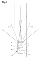
- Fig. 1 is a view illustrating the schematic configuration of an object detecting device according to an embodiment of the present invention.
- an object detecting device 1 is a device that detects an object around a vehicle by radars 3, 4, and 5 installed in a vehicle 2.
- the object detecting device 1 is used as an object detecting means, such as an auto cruise control system for following a preceding vehicle at the time of traffic congestion, a pre-crash brake assist system, and a pre-crash seatbelt system.
- the radars 3 and 4 of the object detecting device 1 function as a detection unit that detects the lateral direction (including the direction inclined with respect to the traveling direction) of the vehicle 2, and detect a predetermined angle range from the central direction of detection with a direction crossing the longitudinal direction of the vehicle 2 as a central direction of detection.
- the radar 3 is fixed to a front left portion of the vehicle 2, is installed with the front left direction of the vehicle 2 as the central direction of detection, and senses the front left region of the vehicle 2.
- the radar 4 is fixed to a front right portion of the vehicle 2, is installed with the front right direction of the vehicle 2 as the central direction of detection, and senses the front right region of the vehicle 2.
- the radars 3 and 4 for example, millimeter wave radars are used.
- FM-CW millimeter wave radars are used.
- the radars 3 and 4 transmit an electric wave with a predetermined frequency to the detection region and receive an observation wave reflected by an object or the like. By performing signal analysis of the received signal, the relative velocity of the object with respect to the vehicle 2 and the distance from the vehicle 2 can be detected.
- the radar 5 functions as a detection unit that detects the front of the vehicle 2, and has the front direction of the vehicle 2 as a central direction of detection and detects a predetermined angle range from the central direction of detection.
- the radar 5 is fixed at the middle position of the front portion of the vehicle 2, is installed with the front direction of the vehicle 2 as the detection direction, and senses the front region of the vehicle 2.
- a millimeter wave radar for example, a millimeter wave radar is used.
- an FM-CW millimeter wave radar is used.
- the radar 5 transmits an electric wave with a predetermined frequency to the detection region and receives an observation wave reflected by an object or the like. By performing signal analysis of the received signal, the relative velocity of the object with respect to the vehicle 2 and the distance from the vehicle 2 can be detected.
- the detection region of the radar 5 is not shown for convenience of explanation.
- radars capable of detecting the detection region of the same range as that of the radar 5 may be used as the radars 3 and 4
- radars having the detection distance shorter than that of the radar 5 may also be used. Also in this case, since the approach of other vehicles from the lateral direction can be sufficiently detected, the power consumption when the radars 3 and 4 operate can be suppressed to be low. In addition, the radar 5 may not be installed when the front region of the vehicle can be sufficiently detected by the radars 3 and 4.
- the object detecting device 1 includes an ECU (Electronic Control Unit) 6.
- the ECU 6 performs overall control of the entire object detecting device 1 and is configured to include as a main subject a computer including a CPU, a ROM, and a RAM, for example.
- the ECU 6 is connected to the radars 3, 4, and 5 so that each detection signal is input to the ECU 6.
- the ECU 6 calculates the relative velocity of an object or the like existing in the detection region and the distance to the vehicle 2 by performing signal processing on the detection signals.
- the ECU 6 functions as a velocity calculating unit that calculates the absolute velocity of the object, which exists in the lateral direction of the vehicle 2, in the horizontal direction (vehicle width direction) of the vehicle on the basis of the detection signals of the radars 3 and 4.
- the ECU 6 functions as a determination unit that determines whether or not the object is an approaching moving object on the basis of the calculated absolute velocity of the object in the horizontal direction of the vehicle.
- the object detecting device 1 includes a vehicle velocity sensor 7.
- the vehicle velocity sensor 7 functions as a vehicle velocity detecting unit that detects the travel velocity of the vehicle 2 and, for example, a wheel velocity sensor is used.
- the vehicle velocity sensor 7 is connected to the ECU 6, and the detection signal is input to the ECU 6.
- the alarm section 8 functions as an alarming means that alarms the driver of the vehicle 2 when an object approaching the vehicle 2 is detected. Anything capable of warning the driver of the approach of an object may be used as the alarm section 8. For example, a warning of the occurrence of trouble may be given through visual methods, such as lamp lighting, LED lighting, and liquid crystal display, or acoustic methods, such as a buzzer and sound.
- the alarm section 8 is connected to the ECU 6 and performs an alarm operation when an alarm instruction signal is output from the ECU 6.
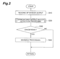
- Fig. 2 is a flow chart illustrating the object detection processing of the, object detecting device 1 and the object detecting method according to the present embodiment. Control processing in Fig. 2 is repeatedly executed for every predetermined time by the ECU 6, for example.
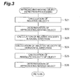
- Fig. 3 is a flow chart illustrating the approaching moving object detection processing of the object detecting device 1 according to the present embodiment.
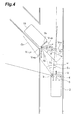
- Fig. 4 is an explanatory view at the time of the approach of the vehicle from the lateral direction in the object detecting device 1 according to the present embodiment. In Fig. 4 , the case where another vehicle 10 approaching from the lateral direction is detected by the radar 3 is shown.
- the object detecting device 1 operates when the vehicle 2 travels and detects an object in the detection region around the vehicle 2 by the radars 3, 4, and 5.
- reading processing of the sensor output is first performed as shown in S 10 of Fig. 2 . That is, the detection signals of the radars 3, 4, and 5 and the detection signal of the vehicle velocity sensor 7 are read.
- the detection signals of the radars 3, 4, and 5 for example, a beat signal obtained by mixing a transmitted wave and a received wave is read.
- the approaching moving object detection processing is processing for calculating the relative velocity of the detected object with respect to the vehicle 2 on the basis of the sensor output information, calculating the absolute velocity of the object, and detecting whether or not the detected object is an approaching moving object on the basis of the absolute velocity component of the object in the horizontal direction (vehicle width direction) of the vehicle 2. Details of the approaching moving object detection processing will be described later.
- the warning processing is processing for warning the driver of the vehicle 2 that there is an approaching moving object.
- the alarm section 8 receives a command signal from the ECU 6 and performs a warning operation by lamp lighting, panel display, buzzer output, voice output, and the like. Then, when the warning processing of S40 is finished, the control processing series is ended.
- the object detection can be performed by determining accurately whether the detected object is an approaching moving object or a stationary object by calculating the relative velocity of the detected object with respect to the vehicle 2, calculating the absolute velocity of the object, and determining whether or not the detected object is an approaching moving object on the basis of the absolute velocity component of the object in the horizontal direction (vehicle width direction) of the vehicle 2. Accordingly, the danger of the approaching moving object can be determined appropriately.
- the approaching moving object detection processing is processing executed in S20 of Fig. 2 , and the absolute velocity of the detected object in the horizontal direction of the vehicle 2 is calculated and it is determined whether or not the object is an approaching moving object on the basis of the absolute velocity.
- This approaching moving object detection processing is suitable for detecting the approaching moving object from the lateral direction and is mainly performed on the basis of the detection signals of the radars 3 and 4.
- the relative velocity calculation processing is processing for calculating the relative velocity of the detected object with respect to the vehicle 2 and is performed by performing signal processing of the beat signals in the radars 3 and 4.
- This determination processing is processing for determining whether or not the detected object is an approaching moving object. For example, it is determined whether the detected object is an approaching moving object, a moving object becoming distant, or a stationary object on the basis of whether or not the following determination expressions (1) and (2) shown below are satisfied.
- 'V' is a travel velocity of the vehicle 2
- 'Vr' is a relative velocity of the vehicle 2 with respect to the object
- ' ⁇ 0' is an angle formed by the traveling direction of the vehicle 2 and the direction from the vehicle 2 to the object (refer to Fig. 4 ).
- expresses a velocity component of the vehicle velocity in the direction from the vehicle 2 to the object.
- THVR1 is a threshold value for determination on becoming distant, and a positive velocity value is set.
- THVR2 is a threshold value for approach determination, and a negative velocity value is set.
- the determination expression (1) it is determined that the detected object is a moving object becoming distant.
- the determination expression (2) the detected object is determined to be an approaching moving object and is temporarily registered as an approaching moving object.
- the determination expressions (1) and (2) it is determined that the detected object is a stationary object.
- the processing for calculating the relative velocity in the radial direction is processing for calculating the relative velocity Vrd in the radial direction of the object by composition of the horizontal velocity Vx and the longitudinal velocity Vy with respect to the radar axis (detection direction) Or.
- 'Vx' is a horizontal velocity component of the object in a direction perpendicular to the radar axis Or and is calculated on the basis of the velocity value and velocity direction of the relative velocity Vr.
- 'Vy' is a longitudinal velocity component of the object in a direction parallel to the radar axis Or and is calculated on the basis of the velocity value and velocity direction of the relative velocity Vr.
- the process proceeds to S24 in which the processing for calculating the relative velocity of the object in the horizontal direction with respect to the traveling direction of the vehicle 2 and the relative velocity of the object with respect to the traveling direction of the vehicle 2 is performed.
- the relative velocity Vobjx of the object in the horizontal direction (vehicle width direction) with respect to the traveling direction of the vehicle 2 is calculated by the following expression (4).
- Vobjx Vrd ⁇ cos ⁇ ⁇ 2
- ⁇ ⁇ 2 90 - ⁇ - ⁇ ⁇ 1
- ⁇ is a setting angle of the radar 3 and is expressed as an angle formed by the longitudinal direction of the vehicle 2 and the central direction of detection (radar axis Or) of the radar 3.
- ' ⁇ 1' is an angle formed by the direction of the longitudinal velocity Vy and the direction of the relative velocity Vrd and is expressed by the following expression (6).
- ⁇ ⁇ 1 arctan Vx / Vy
- Vobjx Vrd ⁇ sin ⁇ ⁇ 2
- This calculation processing is processing for calculating the absolute velocity of the detected object.
- Vrd2 of the object is calculated by the following expression (8).
- Vrd ⁇ 2 Vobjx 2 + Vobjy ⁇ 2 2 1 / 2
- 'Vobjy2' is the absolute velocity of the object in the vehicle traveling direction, which is obtained by subtracting the vehicle velocity V of the vehicle 2 from the relative velocity Vobjy of the object with respect to the traveling direction of the vehicle 2.
- the absolute velocity Vobjy2 in the vehicle traveling direction of the object is expressed by the following expression (9).
- Vobjy ⁇ 2 Vobjy - V
- the direction of the absolute velocity Vrd2 of the object is a direction inclined by ⁇ 3 from the horizontal direction of the vehicle 2.
- the ⁇ 3 is expressed by the following expression (10).
- ⁇ ⁇ 3 arctan Vobjx / Vrd ⁇ 2
- 'Vobjx' is a velocity component of the absolute velocity Vrd2 of the object in the horizontal direction of the vehicle 2 and is an absolute velocity of the object in the horizontal direction of the vehicle 2.
- 'Vobjy2' is a velocity component of the absolute velocity Vrd2 of the object in the traveling direction of the vehicle 2 and is an absolute velocity of the object in the traveling direction of the vehicle 2.
- the process proceeds to S26 in which it is determined whether or not the detected object is an approaching moving object. That is, in S22, an object temporarily registered as an approaching moving object is determined to be an approaching moving object and is finally registered. In addition, in S22, it is determined whether or not an object not determined to be an approaching moving object is an approaching moving object on the basis of the absolute velocity (Vobjx) of the object in the horizontal direction of the vehicle 2.
- Vobjx absolute velocity
- a state of the absolute velocity Vobjx is determined using the determination result when repeatedly performing the velocity calculation of the object at predetermined periods.
- the number of times of determination it may be determined whether the number of times, in which the absolute velocity Vobjx is equal to or larger than the velocity determination threshold THobjx1, of the predetermined number of times is equal to or larger than the threshold value THobjxcnt1 for determination of the number of times.
- the object is determined to be an approaching moving object and is finally registered.
- the continuous number of times in which the absolute velocity Vobjx of the object in the horizontal direction of the vehicle 2 is equal to or larger than the velocity determination threshold value THobjx1 is not equal to or larger than the threshold value THobjxcnt1 for determination of the number of times, it is determined that the object is not an approaching moving object.
- the object be determined to be an approaching moving object under predetermined conditions if there is a possibility that the object will collide with the vehicle 2.
- the collision possibility of an object and a front portion (for example, a front bumper portion) of the vehicle 2 is determined on the basis of the absolute velocity Vrd2 and absolute position of the object and the velocity V and absolute position of the vehicle 2.
- the velocity determination threshold value THobjx1 and the threshold value THobjxcnt1 for determination of the number of times are changed to threshold values by which a determination as an approaching moving object is easily made, and it is determined again whether or not the object is an approaching moving object. Then, when the determination processing of the approaching moving object of S26 is finished, the control processing series of the approaching moving object detection processing is ended.
- the approaching moving object detection processing of the object detecting device 1 and object detecting method according to the present embodiment it is possible to accurately determine whether or not an object is an approaching moving object by determining whether or not the object is an approaching moving object on the basis of the absolute velocity Vobjx of the object in the horizontal direction (vehicle width direction) of the vehicle 2.
- the absolute velocity Vobjx of the object in the horizontal direction of the vehicle 2 is calculated and it is determined whether or not the object is an approaching moving object on the basis of the calculated absolute velocity Vobjxn in the approaching moving object detection processing described above, it may be determined whether or not the object is an approaching moving object on the basis of the absolute velocity of the object in the horizontal direction of the vehicle 2 using other methods. For example, it may be determined whether or not the object is an approaching moving object on the basis of the relative velocity and relative position of the object with respect to the vehicle 2 using a table, a map, and the like.
- a table or a map which is used for determination, on the basis of the absolute velocity Vobjx of the object in the horizontal direction of the vehicle 2 obtained on the basis of the relative velocity and relative position of the object with respect to the vehicle 2 and to determine whether or not the object is an approaching moving object using the table or the map.
- the object detecting device 1 and the object detecting method according to the present embodiment it is determined whether or not the object is an approaching moving object on the basis of the absolute velocity of the object in the horizontal direction of the vehicle 2. Accordingly, since it is possible to accurately distinguish whether an object existing in the lateral or oblique direction of the vehicle 2 is an approaching moving object or a stationary object, it is possible to appropriately determine whether or not the object is an approaching moving object.
- each embodiment described above shows an example of the object detecting device and object detecting method according to the present invention.
- the object detecting device and the object detecting method according to the present invention are not limited to those described above, and the object detecting device and the object detecting method according to the embodiment may be modified or applied to other things without departing from the scope of the present invention as defmed in the appended claims.
- the object detecting device is not limited to such a method, and detection units other than the FM-CW radar may also be used.
- the present invention can perform appropriate object detection by distinguishing an approaching moving object from a stationary object accurately by detecting the absolute velocity of the object in the horizontal direction of the vehicle.
Landscapes
- Physics & Mathematics (AREA)
- General Physics & Mathematics (AREA)
- Radar Systems Or Details Thereof (AREA)
- Traffic Control Systems (AREA)
Abstract
Description
- The present invention relates to an object detecting device installed in a vehicle and an object detecting method.
- As a known object detecting device installed in a vehicle, there is an object detecting device which detects an object in front of the vehicle, detects the relative positional relationship between the front object and the vehicle, and determines a possibility of collision between the vehicle and the front object on the basis of the relative positional relationship, as disclosed in
JP-A-2005-10893 - In such a device, there is a case where it is difficult to appropriately detect an object approaching from the lateral or oblique direction of the vehicle. For example, in order to detect an object approaching from the lateral or oblique direction of the vehicle, it may be considered to make the detection direction of a sensor inclined with respect to the traveling direction of the vehicle. In this case, it is easy to detect an object approaching from the lateral direction of the vehicle, but it is difficult to identify a stationary object placed on the road or the like and a moving object approaching from the oblique direction of the vehicle.
- That is, when detecting the relative velocity of the object while the vehicle is traveling, the detected relative velocity of the stationary object at the side of the road is gradually decreased as the vehicle approaches the stationary object. This is because the detection direction is different from the approaching direction. In addition, the detected relative velocity of the moving object approaching from the lateral direction of the vehicle is also gradually decreased as the moving object approaches the vehicle. For this reason, since it is difficult to distinguish the moving object approaching from the lateral direction of the vehicle from the stationary object placed at the side of the road, it is difficult to appropriately detect the moving object approaching from the lateral direction of the vehicle.
- Therefore, it is an object of the present invention to provide an object detecting device and an object detecting method capable of performing appropriate object detection by accurately distinguishing an approaching moving object from a stationary object.
- That is, an object detecting device according to the present invention is configured to include: a detection unit that detects the relative velocity of an object, which exists in the lateral direction of a vehicle, with respect to the vehicle; a velocity calculating unit that calculates the absolute velocity of the object in the horizontal direction of the vehicle on the basis of a detection signal of the detection unit; and a determination unit that determines whether or not the object is an approaching moving object on the basis of the absolute velocity of the object in the horizontal direction of the vehicle calculated by the velocity calculating unit.
- According to the present invention, by determining whether or not an object is an approaching moving object on the basis of the absolute velocity of the object in the horizontal direction of the vehicle, it is possible to accurately distinguish whether an object existing in the lateral or oblique direction of the vehicle is an approaching moving object or a stationary object. As a result, it is possible to appropriately determine whether or not the object is an approaching moving object.
- In addition, in the object detecting device according to the present invention, it is preferable that the detection unit be installed in the vehicle with a direction crossing the longitudinal direction of the vehicle as the central direction of detection.
- According to the present invention, appropriate object detection can be performed by accurately distinguishing an approaching moving object from a stationary object by detecting the absolute velocity of the object in the horizontal direction of the vehicle.
- In addition, an object detecting method according to the present invention is configured to include: a detection step of detecting the relative velocity of an object, which exists in the lateral direction of a vehicle, with respect to the vehicle; a velocity calculating step of calculating the absolute velocity of the object in the horizontal direction of the vehicle on the basis of a detection signal in the detection step; and a determination step of determining whether or not the object is an approaching moving object on the basis of the absolute velocity of the object in the horizontal direction of the vehicle calculated in the velocity calculating step.
- According to the present invention, by determining whether or not an object is an approaching moving object on the basis of the absolute velocity of the object in the horizontal direction of the vehicle, it is possible to accurately distinguish whether an object existing in the lateral or oblique direction of the vehicle is an approaching moving object or a stationary object. As a result, it is possible to appropriately determine whether or not the object is an approaching moving object.
-
-
Fig. 1 is a view illustrating the schematic configuration of an object detecting device according to an embodiment of the present invention. -
Fig. 2 is a flow chart illustrating the object detection processing in the object detecting device and the object detecting method inFig. 1 . -
Fig. 3 is a flow chart illustrating the approaching moving object detection processing in the object detecting device and the object detecting method inFig. 1 . -
Fig. 4 is an explanatory view when the object detecting device inFig. 1 performs lateral object detection. - Hereinafter, an embodiment of the present invention will be described in detail with reference to the accompanying drawings. In addition, the same elements are denoted by the same reference numerals in explaining the drawings, and the repeated explanation thereof is omitted.
-
Fig. 1 is a view illustrating the schematic configuration of an object detecting device according to an embodiment of the present invention. - As shown in
Fig. 1 , an object detecting device 1 according to the present embodiment is a device that detects an object around a vehicle byradars vehicle 2. For example, the object detecting device 1 is used as an object detecting means, such as an auto cruise control system for following a preceding vehicle at the time of traffic congestion, a pre-crash brake assist system, and a pre-crash seatbelt system. - The
radars vehicle 2, and detect a predetermined angle range from the central direction of detection with a direction crossing the longitudinal direction of thevehicle 2 as a central direction of detection. For example, theradar 3 is fixed to a front left portion of thevehicle 2, is installed with the front left direction of thevehicle 2 as the central direction of detection, and senses the front left region of thevehicle 2. In addition, theradar 4 is fixed to a front right portion of thevehicle 2, is installed with the front right direction of thevehicle 2 as the central direction of detection, and senses the front right region of thevehicle 2. - As the
radars radars vehicle 2 and the distance from thevehicle 2 can be detected. - The
radar 5 functions as a detection unit that detects the front of thevehicle 2, and has the front direction of thevehicle 2 as a central direction of detection and detects a predetermined angle range from the central direction of detection. For example, theradar 5 is fixed at the middle position of the front portion of thevehicle 2, is installed with the front direction of thevehicle 2 as the detection direction, and senses the front region of thevehicle 2. - As the
radar 5, for example, a millimeter wave radar is used. Preferably, an FM-CW millimeter wave radar is used. Theradar 5 transmits an electric wave with a predetermined frequency to the detection region and receives an observation wave reflected by an object or the like. By performing signal analysis of the received signal, the relative velocity of the object with respect to thevehicle 2 and the distance from thevehicle 2 can be detected. Moreover, inFig. 1 , the detection region of theradar 5 is not shown for convenience of explanation. - Although radars capable of detecting the detection region of the same range as that of the
radar 5 may be used as theradars radar 5 may also be used. Also in this case, since the approach of other vehicles from the lateral direction can be sufficiently detected, the power consumption when theradars radar 5 may not be installed when the front region of the vehicle can be sufficiently detected by theradars - The object detecting device 1 includes an ECU (Electronic Control Unit) 6. The ECU 6 performs overall control of the entire object detecting device 1 and is configured to include as a main subject a computer including a CPU, a ROM, and a RAM, for example.
- The
ECU 6 is connected to theradars ECU 6. In addition, theECU 6 calculates the relative velocity of an object or the like existing in the detection region and the distance to thevehicle 2 by performing signal processing on the detection signals. In addition, theECU 6 functions as a velocity calculating unit that calculates the absolute velocity of the object, which exists in the lateral direction of thevehicle 2, in the horizontal direction (vehicle width direction) of the vehicle on the basis of the detection signals of theradars ECU 6 functions as a determination unit that determines whether or not the object is an approaching moving object on the basis of the calculated absolute velocity of the object in the horizontal direction of the vehicle. - The object detecting device 1 includes a
vehicle velocity sensor 7. Thevehicle velocity sensor 7 functions as a vehicle velocity detecting unit that detects the travel velocity of thevehicle 2 and, for example, a wheel velocity sensor is used. Thevehicle velocity sensor 7 is connected to theECU 6, and the detection signal is input to theECU 6. - In addition, it is preferable to provide an
alarm section 8 in the object detecting device 1. Thealarm section 8 functions as an alarming means that alarms the driver of thevehicle 2 when an object approaching thevehicle 2 is detected. Anything capable of warning the driver of the approach of an object may be used as thealarm section 8. For example, a warning of the occurrence of trouble may be given through visual methods, such as lamp lighting, LED lighting, and liquid crystal display, or acoustic methods, such as a buzzer and sound. Thealarm section 8 is connected to theECU 6 and performs an alarm operation when an alarm instruction signal is output from theECU 6. - Next, an operation of the object detecting device 1 according to the present embodiment will be described.
Fig. 2 is a flow chart illustrating the object detection processing of the, object detecting device 1 and the object detecting method according to the present embodiment. Control processing inFig. 2 is repeatedly executed for every predetermined time by theECU 6, for example.Fig. 3 is a flow chart illustrating the approaching moving object detection processing of the object detecting device 1 according to the present embodiment.Fig. 4 is an explanatory view at the time of the approach of the vehicle from the lateral direction in the object detecting device 1 according to the present embodiment. InFig. 4 , the case where anothervehicle 10 approaching from the lateral direction is detected by theradar 3 is shown. - The object detecting device 1 operates when the
vehicle 2 travels and detects an object in the detection region around thevehicle 2 by theradars S 10 ofFig. 2 . That is, the detection signals of theradars vehicle velocity sensor 7 are read. As the detection signals of theradars - Then, the process proceeds to S20 in which the approaching moving object detection processing is performed. The approaching moving object detection processing is processing for calculating the relative velocity of the detected object with respect to the
vehicle 2 on the basis of the sensor output information, calculating the absolute velocity of the object, and detecting whether or not the detected object is an approaching moving object on the basis of the absolute velocity component of the object in the horizontal direction (vehicle width direction) of thevehicle 2. Details of the approaching moving object detection processing will be described later. - Then, the process proceeds to S30 where when the approaching moving object which approaches the
vehicle 2 has been detected in the approaching moving object detection processing, it is determined whether or not the approach is dangerous. When it is determined that there is no danger in S30, the control processing series is ended. On the other hand, when it is determined that there is a danger in S30 (S40), warning processing is performed. - The warning processing is processing for warning the driver of the
vehicle 2 that there is an approaching moving object. For example, thealarm section 8 receives a command signal from theECU 6 and performs a warning operation by lamp lighting, panel display, buzzer output, voice output, and the like. Then, when the warning processing of S40 is finished, the control processing series is ended. - According to the object detection processing, the object detection can be performed by determining accurately whether the detected object is an approaching moving object or a stationary object by calculating the relative velocity of the detected object with respect to the
vehicle 2, calculating the absolute velocity of the object, and determining whether or not the detected object is an approaching moving object on the basis of the absolute velocity component of the object in the horizontal direction (vehicle width direction) of thevehicle 2. Accordingly, the danger of the approaching moving object can be determined appropriately. - Next, the approaching moving object detection processing of the object detecting device 1 and the object detecting method according to the present embodiment will be described.
- The approaching moving object detection processing is processing executed in S20 of
Fig. 2 , and the absolute velocity of the detected object in the horizontal direction of thevehicle 2 is calculated and it is determined whether or not the object is an approaching moving object on the basis of the absolute velocity. This approaching moving object detection processing is suitable for detecting the approaching moving object from the lateral direction and is mainly performed on the basis of the detection signals of theradars - First, as shown in S21 of
Fig. 3 , processing for calculating the relative velocity of the detected object with respect to thevehicle 2 is performed. The relative velocity calculation processing is processing for calculating the relative velocity of the detected object with respect to thevehicle 2 and is performed by performing signal processing of the beat signals in theradars - Then, the process proceeds to S22 in which determination processing is performed on the approaching moving object. This determination processing is processing for determining whether or not the detected object is an approaching moving object. For example, it is determined whether the detected object is an approaching moving object, a moving object becoming distant, or a stationary object on the basis of whether or not the following determination expressions (1) and (2) shown below are satisfied.


- In these determination expressions (1) and (2), 'V' is a travel velocity of the
vehicle 2, 'Vr' is a relative velocity of thevehicle 2 with respect to the object, and 'θ0' is an angle formed by the traveling direction of thevehicle 2 and the direction from thevehicle 2 to the object (refer toFig. 4 ). V·cos|θ0| expresses a velocity component of the vehicle velocity in the direction from thevehicle 2 to the object. THVR1 is a threshold value for determination on becoming distant, and a positive velocity value is set. THVR2 is a threshold value for approach determination, and a negative velocity value is set. - When the determination expression (1) is satisfied, it is determined that the detected object is a moving object becoming distant. When the determination expression (2) is satisfied, the detected object is determined to be an approaching moving object and is temporarily registered as an approaching moving object. In addition, when the determination expressions (1) and (2) are not satisfied, it is determined that the detected object is a stationary object.
- Then, the process proceeds to S23 in which processing for calculating the relative velocity in the radial direction is performed. The processing for calculating the relative velocity in the radial direction is processing for calculating the relative velocity Vrd in the radial direction of the object by composition of the horizontal velocity Vx and the longitudinal velocity Vy with respect to the radar axis (detection direction) Or. The relative velocity Vrd is calculated by the following expression (3), for example.

- 'Vx' is a horizontal velocity component of the object in a direction perpendicular to the radar axis Or and is calculated on the basis of the velocity value and velocity direction of the relative velocity Vr. 'Vy' is a longitudinal velocity component of the object in a direction parallel to the radar axis Or and is calculated on the basis of the velocity value and velocity direction of the relative velocity Vr.
- Then, the process proceeds to S24 in which the processing for calculating the relative velocity of the object in the horizontal direction with respect to the traveling direction of the
vehicle 2 and the relative velocity of the object with respect to the traveling direction of thevehicle 2 is performed. The relative velocity Vobjx of the object in the horizontal direction (vehicle width direction) with respect to the traveling direction of thevehicle 2 is calculated by the following expression (4).
- In this expression (4), 'θ2' is an angle formed by the direction of the relative velocity Vrd in the radial direction and the horizontal direction of the
vehicle 2 and is calculated by the following expression (5).
- In this expression (5), α is a setting angle of the
radar 3 and is expressed as an angle formed by the longitudinal direction of thevehicle 2 and the central direction of detection (radar axis Or) of theradar 3. In addition, 'θ1' is an angle formed by the direction of the longitudinal velocity Vy and the direction of the relative velocity Vrd and is expressed by the following expression (6).
- The relative velocity Vobjx of the object with respect to the traveling direction of the
vehicle 2 is calculated by the following expression (7).
- Then, the process proceeds to S25 in which the processing for calculating the absolute velocity of the object is performed. This calculation processing is processing for calculating the absolute velocity of the detected object. For example, the absolute velocity Vrd2 of the object is calculated by the following expression (8).

- In this expression (8), 'Vobjy2' is the absolute velocity of the object in the vehicle traveling direction, which is obtained by subtracting the vehicle velocity V of the
vehicle 2 from the relative velocity Vobjy of the object with respect to the traveling direction of thevehicle 2. The absolute velocity Vobjy2 in the vehicle traveling direction of the object is expressed by the following expression (9).
- The direction of the absolute velocity Vrd2 of the object is a direction inclined by θ3 from the horizontal direction of the
vehicle 2. The θ3 is expressed by the following expression (10).
vehicle 2 and is an absolute velocity of the object in the horizontal direction of thevehicle 2. In addition, 'Vobjy2' is a velocity component of the absolute velocity Vrd2 of the object in the traveling direction of thevehicle 2 and is an absolute velocity of the object in the traveling direction of thevehicle 2. - Then, the process proceeds to S26 in which it is determined whether or not the detected object is an approaching moving object. That is, in S22, an object temporarily registered as an approaching moving object is determined to be an approaching moving object and is finally registered. In addition, in S22, it is determined whether or not an object not determined to be an approaching moving object is an approaching moving object on the basis of the absolute velocity (Vobjx) of the object in the horizontal direction of the
vehicle 2. - For example, it is determined whether the continuous number of times, in which the absolute velocity Vobjx of the object in the horizontal direction of the
vehicle 2 is equal to or larger than the velocity determination threshold value THobjx1, is equal to or larger than the threshold value THobjxcnt1 for determination of the number of times. In this determination, a state of the absolute velocity Vobjx is determined using the determination result when repeatedly performing the velocity calculation of the object at predetermined periods. In this case, for the number of times of determination, it may be determined whether the number of times, in which the absolute velocity Vobjx is equal to or larger than the velocity determination threshold THobjx1, of the predetermined number of times is equal to or larger than the threshold value THobjxcnt1 for determination of the number of times. - In addition, when the continuous number of times, in which the absolute velocity Vobjx of the object in the horizontal direction of the
vehicle 2 is equal to or larger than the velocity determination threshold value THobjx1, is equal to or larger than the threshold value THobjxcnt1 for determination of the number of times, the object is determined to be an approaching moving object and is finally registered. On the other hand, when the continuous number of times, in which the absolute velocity Vobjx of the object in the horizontal direction of thevehicle 2 is equal to or larger than the velocity determination threshold value THobjx1, is not equal to or larger than the threshold value THobjxcnt1 for determination of the number of times, it is determined that the object is not an approaching moving object. - In addition, when the continuous number of times, in which the absolute velocity Vobjx of the object in the horizontal direction of the
vehicle 2 is equal to or larger than the velocity determination threshold value THobjx1, is not equal to or larger than the threshold value THobjxcnt1 for determination on the number of times, it is preferable that the object be determined to be an approaching moving object under predetermined conditions if there is a possibility that the object will collide with thevehicle 2. For example, the collision possibility of an object and a front portion (for example, a front bumper portion) of thevehicle 2 is determined on the basis of the absolute velocity Vrd2 and absolute position of the object and the velocity V and absolute position of thevehicle 2. When the collision possibility is equal to or larger than a predetermined level, the velocity determination threshold value THobjx1 and the threshold value THobjxcnt1 for determination of the number of times are changed to threshold values by which a determination as an approaching moving object is easily made, and it is determined again whether or not the object is an approaching moving object. Then, when the determination processing of the approaching moving object of S26 is finished, the control processing series of the approaching moving object detection processing is ended. - According to the approaching moving object detection processing of the object detecting device 1 and object detecting method according to the present embodiment, it is possible to accurately determine whether or not an object is an approaching moving object by determining whether or not the object is an approaching moving object on the basis of the absolute velocity Vobjx of the object in the horizontal direction (vehicle width direction) of the
vehicle 2. - In addition, although the absolute velocity Vobjx of the object in the horizontal direction of the
vehicle 2 is calculated and it is determined whether or not the object is an approaching moving object on the basis of the calculated absolute velocity Vobjxn in the approaching moving object detection processing described above, it may be determined whether or not the object is an approaching moving object on the basis of the absolute velocity of the object in the horizontal direction of thevehicle 2 using other methods. For example, it may be determined whether or not the object is an approaching moving object on the basis of the relative velocity and relative position of the object with respect to thevehicle 2 using a table, a map, and the like. Specifically, it is preferable to set a table or a map, which is used for determination, on the basis of the absolute velocity Vobjx of the object in the horizontal direction of thevehicle 2 obtained on the basis of the relative velocity and relative position of the object with respect to thevehicle 2 and to determine whether or not the object is an approaching moving object using the table or the map. - As described above, according to the object detecting device 1 and the object detecting method according to the present embodiment, it is determined whether or not the object is an approaching moving object on the basis of the absolute velocity of the object in the horizontal direction of the
vehicle 2. Accordingly, since it is possible to accurately distinguish whether an object existing in the lateral or oblique direction of thevehicle 2 is an approaching moving object or a stationary object, it is possible to appropriately determine whether or not the object is an approaching moving object. - In addition, each embodiment described above shows an example of the object detecting device and object detecting method according to the present invention. The object detecting device and the object detecting method according to the present invention are not limited to those described above, and the object detecting device and the object detecting method according to the embodiment may be modified or applied to other things without departing from the scope of the present invention as defmed in the appended claims.
- For example, in each embodiment described above, the case where the FM-CW radar is used as a detection unit has been described. However, the object detecting device according to the present invention is not limited to such a method, and detection units other than the FM-CW radar may also be used.
- The present invention can perform appropriate object detection by distinguishing an approaching moving object from a stationary object accurately by detecting the absolute velocity of the object in the horizontal direction of the vehicle.
Claims (5)
- An object detecting device comprising:a detection unit that detects the relative velocity of an object, which exists in the lateral direction of a vehicle, with respect to the vehicle;a velocity calculating unit that calculates the absolute velocity of the object in the horizontal direction of the vehicle on the basis of a detection signal of the detection unit; anda determination unit that determines whether or not the object is an approaching moving object on the basis of the absolute velocity of the object in the horizontal direction of the vehicle calculated by the velocity calculating unit.
- The object detecting device according to claim 1,
wherein the detection unit is installed in the vehicle with a direction crossing the longitudinal direction of the vehicle as a central direction of detection. - The object detecting device according to claim 1,
wherein the detection unit is a millimeter wave radar. - The object detecting device according to claim 1,
wherein the velocity calculating unit and the determination unit are configured by an electronic control unit. - An object detecting method comprising:a detection step of detecting the relative velocity of an object, which exists in the lateral direction of a vehicle, with respect to the vehicle;a velocity calculating step of calculating the absolute velocity of the object in the horizontal direction of the vehicle on the basis of a detection signal in the detection step; anda determination step of determining whether or not the object is an approaching moving object on the basis of the absolute velocity of the object in the horizontal direction of the vehicle calculated in the velocity calculating step.
Applications Claiming Priority (2)
| Application Number | Priority Date | Filing Date | Title |
|---|---|---|---|
| JP2007127213A JP4811343B2 (en) | 2007-05-11 | 2007-05-11 | Object detection device |
| PCT/JP2008/058894 WO2008143114A1 (en) | 2007-05-11 | 2008-05-08 | Object detecting device, and object detecting method |
Publications (3)
| Publication Number | Publication Date |
|---|---|
| EP2151809A1 true EP2151809A1 (en) | 2010-02-10 |
| EP2151809A4 EP2151809A4 (en) | 2010-10-27 |
| EP2151809B1 EP2151809B1 (en) | 2018-12-12 |
Family
ID=40031822
Family Applications (1)
| Application Number | Title | Priority Date | Filing Date |
|---|---|---|---|
| EP08752755.2A Not-in-force EP2151809B1 (en) | 2007-05-11 | 2008-05-08 | Object detecting device, and object detecting method |
Country Status (5)
| Country | Link |
|---|---|
| US (1) | US8718916B2 (en) |
| EP (1) | EP2151809B1 (en) |
| JP (1) | JP4811343B2 (en) |
| CN (1) | CN101681560B (en) |
| WO (1) | WO2008143114A1 (en) |
Families Citing this family (18)
| Publication number | Priority date | Publication date | Assignee | Title |
|---|---|---|---|---|
| JP5310760B2 (en) * | 2011-03-04 | 2013-10-09 | トヨタ自動車株式会社 | Approaching vehicle detection device |
| CN104380362A (en) * | 2012-06-26 | 2015-02-25 | 丰田自动车株式会社 | Vehicle warning device |
| US9409575B2 (en) * | 2012-11-26 | 2016-08-09 | Honda Motor Co., Ltd. | Vehicle control device |
| JP5949721B2 (en) * | 2013-10-10 | 2016-07-13 | 株式会社デンソー | Predecessor selection device |
| JP5799238B1 (en) | 2014-03-28 | 2015-10-21 | パナソニックIpマネジメント株式会社 | Wireless device, processing device, and processing system |
| JP5866511B2 (en) * | 2014-03-28 | 2016-02-17 | パナソニックIpマネジメント株式会社 | Wireless device, processing device, and processing system |
| US9995386B2 (en) * | 2015-02-12 | 2018-06-12 | Honda Motor Co., Ltd. | Transmission control device for automatic transmission |
| JP6970936B2 (en) * | 2016-12-20 | 2021-11-24 | パナソニックIpマネジメント株式会社 | Object detector, object detection program, and recording medium |
| KR102295577B1 (en) * | 2017-02-08 | 2021-08-30 | 현대자동차주식회사 | Ecu, autonomous vehicle including the ecu, and method of determing driving lane for the same |
| JP6892600B2 (en) * | 2017-07-12 | 2021-06-23 | ミツミ電機株式会社 | Object detection method and object detection device |
| CN109910877B (en) * | 2019-02-01 | 2020-08-07 | 中科安达(北京)科技有限公司 | Method for intelligently identifying obstacles by AEBS (automatic acoustic Spectroscopy) |
| US20220317288A1 (en) * | 2019-08-02 | 2022-10-06 | Mitsubishi Electric Corporation | Vehicle-mounted object detection device |
| US11531107B2 (en) * | 2019-11-19 | 2022-12-20 | Volvo Car Corporation | Long range LIDAR-based speed estimation |
| TWI765208B (en) * | 2020-01-06 | 2022-05-21 | 為升電裝工業股份有限公司 | Blind spot detection system with speed detection function and device and method thereof |
| CN111289980B (en) * | 2020-03-06 | 2022-03-08 | 成都纳雷科技有限公司 | Roadside stationary object detection method and system based on vehicle-mounted millimeter wave radar |
| CN111797701B (en) * | 2020-06-10 | 2024-05-24 | 广东正扬传感科技股份有限公司 | Road obstacle sensing method and system for vehicle multi-sensor fusion system |
| JP2022011470A (en) * | 2020-06-30 | 2022-01-17 | 京楽産業.株式会社 | Pachinko machine |
| CN118033621B (en) * | 2024-02-23 | 2024-11-19 | 北京集度科技有限公司 | Object detection method, device, computer equipment and storage medium |
Family Cites Families (24)
| Publication number | Priority date | Publication date | Assignee | Title |
|---|---|---|---|---|
| JP2952796B2 (en) * | 1991-12-27 | 1999-09-27 | 本田技研工業株式会社 | Vehicle collision judgment device |
| JP3271473B2 (en) * | 1995-05-23 | 2002-04-02 | 日産自動車株式会社 | Inter-vehicle distance notification device |
| JPH09188206A (en) * | 1996-01-08 | 1997-07-22 | Nissan Motor Co Ltd | Blind spot obstacle notification device |
| DE19647660B4 (en) * | 1996-11-19 | 2005-09-01 | Daimlerchrysler Ag | Tripping device for occupant restraint systems in a vehicle |
| DE19845568A1 (en) * | 1998-04-23 | 1999-10-28 | Volkswagen Ag | Object detection device for motor vehicles |
| JP4179577B2 (en) | 2000-01-20 | 2008-11-12 | 富士通株式会社 | Radar wave relay device for approach notification |
| JP3427809B2 (en) | 2000-03-09 | 2003-07-22 | 株式会社デンソー | Vehicle road shape recognition method and apparatus, recording medium |
| JP2003072416A (en) * | 2001-08-31 | 2003-03-12 | Denso Corp | Travel control device for vehicles |
| US6873251B2 (en) * | 2002-07-16 | 2005-03-29 | Delphi Technologies, Inc. | Tracking system and method employing multiple overlapping sensors |
| JP3849650B2 (en) | 2003-01-28 | 2006-11-22 | トヨタ自動車株式会社 | vehicle |
| JP3991928B2 (en) | 2003-06-17 | 2007-10-17 | 日産自動車株式会社 | Vehicle contact avoidance control device |
| JP4281485B2 (en) * | 2003-09-11 | 2009-06-17 | トヨタ自動車株式会社 | Start-up control device for collision damage mitigation device and sensor used therefor |
| DE10352800A1 (en) * | 2003-11-12 | 2005-06-23 | Robert Bosch Gmbh | Device for detecting moving objects |
| DE10356309A1 (en) * | 2003-11-28 | 2005-06-23 | Robert Bosch Gmbh | Method and device for warning the driver of a motor vehicle |
| US7409295B2 (en) * | 2004-08-09 | 2008-08-05 | M/A-Com, Inc. | Imminent-collision detection system and process |
| DE102004038734A1 (en) * | 2004-08-10 | 2006-02-23 | Robert Bosch Gmbh | Method and device for triggering emergency braking |
| JP4069919B2 (en) | 2004-09-28 | 2008-04-02 | 日産自動車株式会社 | Collision determination device and method |
| JP2006188129A (en) * | 2005-01-05 | 2006-07-20 | Hitachi Ltd | Collision load reduction vehicle system |
| DE102005003194A1 (en) * | 2005-01-24 | 2006-07-27 | Robert Bosch Gmbh | Motor vehicle driver assistance system, has comparator to compare objects` absolute velocities and threshold values, which vary as function of factors that influences objects` relative velocities and vehicle velocity determination accuracy |
| JP2006221498A (en) * | 2005-02-14 | 2006-08-24 | Hitachi Ltd | Driving assistance device |
| JP2006298105A (en) * | 2005-04-19 | 2006-11-02 | Toyota Motor Corp | Operation control device for occupant protection device |
| JP4442520B2 (en) | 2005-06-27 | 2010-03-31 | 株式会社デンソー | Course estimation device for vehicle |
| JP4684954B2 (en) * | 2005-08-31 | 2011-05-18 | 本田技研工業株式会社 | Vehicle travel safety device |
| JP4306675B2 (en) * | 2005-12-15 | 2009-08-05 | トヨタ自動車株式会社 | VEHICLE DRIVE SUPPORT DEVICE AND VEHICLE CONTROL DEVICE |
-
2007
- 2007-05-11 JP JP2007127213A patent/JP4811343B2/en not_active Expired - Fee Related
-
2008
- 2008-05-08 WO PCT/JP2008/058894 patent/WO2008143114A1/en not_active Ceased
- 2008-05-08 EP EP08752755.2A patent/EP2151809B1/en not_active Not-in-force
- 2008-05-08 CN CN2008800157301A patent/CN101681560B/en not_active Expired - Fee Related
- 2008-05-08 US US12/597,355 patent/US8718916B2/en not_active Expired - Fee Related
Also Published As
| Publication number | Publication date |
|---|---|
| WO2008143114A1 (en) | 2008-11-27 |
| EP2151809B1 (en) | 2018-12-12 |
| CN101681560B (en) | 2013-03-13 |
| EP2151809A4 (en) | 2010-10-27 |
| JP2008282279A (en) | 2008-11-20 |
| JP4811343B2 (en) | 2011-11-09 |
| CN101681560A (en) | 2010-03-24 |
| US20100131153A1 (en) | 2010-05-27 |
| US8718916B2 (en) | 2014-05-06 |
Similar Documents
| Publication | Publication Date | Title |
|---|---|---|
| EP2151809B1 (en) | Object detecting device, and object detecting method | |
| US8248295B2 (en) | Pre-crash safety system | |
| JP4990424B2 (en) | Driving support device | |
| US8305254B2 (en) | Object detecting apparatus | |
| JP5878491B2 (en) | Driving assistance device | |
| CN103909926B (en) | The lateral collision-proof method of vehicle, equipment and system | |
| US20110291874A1 (en) | Vehicle radar system and method for detecting objects | |
| JP5953716B2 (en) | Vehicle control apparatus, specific object determination apparatus, specific object determination method, specific object determination program | |
| EP3176603B1 (en) | A vehicle radar system | |
| CN105480229A (en) | An intelligent lane change assistance system and method based on information fusion | |
| US20150187217A1 (en) | Collision avoidance system and method for vehicles | |
| CN104837683A (en) | Parking space detector | |
| JP2013156147A (en) | Surrounding object detection device | |
| EP3293545A1 (en) | Determining relative velocity in a vehicle radar system | |
| EP2100164B1 (en) | Surroundings monitoring apparatus for a motor vehicle | |
| CN113228133A (en) | Driving support device | |
| JP2013045142A (en) | Approach warning device, approach warning method, program, and medium | |
| EP3413082A1 (en) | A vehicle system for detection of oncoming vehicles | |
| JP4992640B2 (en) | Object detection device | |
| WO2023047616A1 (en) | Host vehicle blind spot monitoring system and host vehicle blind spot monitoring method | |
| EP3816668A1 (en) | Vehicle control device and vehicle control method | |
| JP4684876B2 (en) | Radar device and method for detecting object of radar device | |
| KR100534706B1 (en) | The distance between vehicles going in the same direction alarm control method | |
| EP4113479A1 (en) | Apparatus for collision warning and vehicle including the same | |
| JP2008146482A (en) | Collision determination device |
Legal Events
| Date | Code | Title | Description |
|---|---|---|---|
| PUAI | Public reference made under article 153(3) epc to a published international application that has entered the european phase |
Free format text: ORIGINAL CODE: 0009012 |
|
| 17P | Request for examination filed |
Effective date: 20091209 |
|
| AK | Designated contracting states |
Kind code of ref document: A1 Designated state(s): AT BE BG CH CY CZ DE DK EE ES FI FR GB GR HR HU IE IS IT LI LT LU LV MC MT NL NO PL PT RO SE SI SK TR |
|
| AX | Request for extension of the european patent |
Extension state: AL BA MK RS |
|
| DAX | Request for extension of the european patent (deleted) | ||
| A4 | Supplementary search report drawn up and despatched |
Effective date: 20100927 |
|
| RAP1 | Party data changed (applicant data changed or rights of an application transferred) |
Owner name: TOYOTA JIDOSHA KABUSHIKI KAISHA |
|
| 17Q | First examination report despatched |
Effective date: 20130408 |
|
| GRAP | Despatch of communication of intention to grant a patent |
Free format text: ORIGINAL CODE: EPIDOSNIGR1 |
|
| STAA | Information on the status of an ep patent application or granted ep patent |
Free format text: STATUS: GRANT OF PATENT IS INTENDED |
|
| RIC1 | Information provided on ipc code assigned before grant |
Ipc: B60W 30/08 20060101ALI20180703BHEP Ipc: G08G 1/16 20060101AFI20180703BHEP Ipc: B60R 21/0134 20060101ALI20180703BHEP Ipc: B60R 21/00 20060101ALI20180703BHEP |
|
| INTG | Intention to grant announced |
Effective date: 20180730 |
|
| GRAS | Grant fee paid |
Free format text: ORIGINAL CODE: EPIDOSNIGR3 |
|
| GRAA | (expected) grant |
Free format text: ORIGINAL CODE: 0009210 |
|
| STAA | Information on the status of an ep patent application or granted ep patent |
Free format text: STATUS: THE PATENT HAS BEEN GRANTED |
|
| AK | Designated contracting states |
Kind code of ref document: B1 Designated state(s): AT BE BG CH CY CZ DE DK EE ES FI FR GB GR HR HU IE IS IT LI LT LU LV MC MT NL NO PL PT RO SE SI SK TR |
|
| REG | Reference to a national code |
Ref country code: GB Ref legal event code: FG4D |
|
| REG | Reference to a national code |
Ref country code: CH Ref legal event code: EP |
|
| REG | Reference to a national code |
Ref country code: AT Ref legal event code: REF Ref document number: 1077012 Country of ref document: AT Kind code of ref document: T Effective date: 20181215 |
|
| REG | Reference to a national code |
Ref country code: DE Ref legal event code: R096 Ref document number: 602008058312 Country of ref document: DE |
|
| REG | Reference to a national code |
Ref country code: IE Ref legal event code: FG4D |
|
| REG | Reference to a national code |
Ref country code: DE Ref legal event code: R084 Ref document number: 602008058312 Country of ref document: DE |
|
| REG | Reference to a national code |
Ref country code: GB Ref legal event code: 746 Effective date: 20190312 |
|
| REG | Reference to a national code |
Ref country code: NL Ref legal event code: MP Effective date: 20181212 |
|
| REG | Reference to a national code |
Ref country code: LT Ref legal event code: MG4D |
|
| PG25 | Lapsed in a contracting state [announced via postgrant information from national office to epo] |
Ref country code: HR Free format text: LAPSE BECAUSE OF FAILURE TO SUBMIT A TRANSLATION OF THE DESCRIPTION OR TO PAY THE FEE WITHIN THE PRESCRIBED TIME-LIMIT Effective date: 20181212 Ref country code: LT Free format text: LAPSE BECAUSE OF FAILURE TO SUBMIT A TRANSLATION OF THE DESCRIPTION OR TO PAY THE FEE WITHIN THE PRESCRIBED TIME-LIMIT Effective date: 20181212 Ref country code: LV Free format text: LAPSE BECAUSE OF FAILURE TO SUBMIT A TRANSLATION OF THE DESCRIPTION OR TO PAY THE FEE WITHIN THE PRESCRIBED TIME-LIMIT Effective date: 20181212 Ref country code: NO Free format text: LAPSE BECAUSE OF FAILURE TO SUBMIT A TRANSLATION OF THE DESCRIPTION OR TO PAY THE FEE WITHIN THE PRESCRIBED TIME-LIMIT Effective date: 20190312 Ref country code: ES Free format text: LAPSE BECAUSE OF FAILURE TO SUBMIT A TRANSLATION OF THE DESCRIPTION OR TO PAY THE FEE WITHIN THE PRESCRIBED TIME-LIMIT Effective date: 20181212 Ref country code: BG Free format text: LAPSE BECAUSE OF FAILURE TO SUBMIT A TRANSLATION OF THE DESCRIPTION OR TO PAY THE FEE WITHIN THE PRESCRIBED TIME-LIMIT Effective date: 20190312 Ref country code: FI Free format text: LAPSE BECAUSE OF FAILURE TO SUBMIT A TRANSLATION OF THE DESCRIPTION OR TO PAY THE FEE WITHIN THE PRESCRIBED TIME-LIMIT Effective date: 20181212 |
|
| REG | Reference to a national code |
Ref country code: AT Ref legal event code: MK05 Ref document number: 1077012 Country of ref document: AT Kind code of ref document: T Effective date: 20181212 |
|
| PG25 | Lapsed in a contracting state [announced via postgrant information from national office to epo] |
Ref country code: GR Free format text: LAPSE BECAUSE OF FAILURE TO SUBMIT A TRANSLATION OF THE DESCRIPTION OR TO PAY THE FEE WITHIN THE PRESCRIBED TIME-LIMIT Effective date: 20190313 Ref country code: SE Free format text: LAPSE BECAUSE OF FAILURE TO SUBMIT A TRANSLATION OF THE DESCRIPTION OR TO PAY THE FEE WITHIN THE PRESCRIBED TIME-LIMIT Effective date: 20181212 |
|
| PG25 | Lapsed in a contracting state [announced via postgrant information from national office to epo] |
Ref country code: NL Free format text: LAPSE BECAUSE OF FAILURE TO SUBMIT A TRANSLATION OF THE DESCRIPTION OR TO PAY THE FEE WITHIN THE PRESCRIBED TIME-LIMIT Effective date: 20181212 |
|
| PG25 | Lapsed in a contracting state [announced via postgrant information from national office to epo] |
Ref country code: PL Free format text: LAPSE BECAUSE OF FAILURE TO SUBMIT A TRANSLATION OF THE DESCRIPTION OR TO PAY THE FEE WITHIN THE PRESCRIBED TIME-LIMIT Effective date: 20181212 Ref country code: IT Free format text: LAPSE BECAUSE OF FAILURE TO SUBMIT A TRANSLATION OF THE DESCRIPTION OR TO PAY THE FEE WITHIN THE PRESCRIBED TIME-LIMIT Effective date: 20181212 Ref country code: CZ Free format text: LAPSE BECAUSE OF FAILURE TO SUBMIT A TRANSLATION OF THE DESCRIPTION OR TO PAY THE FEE WITHIN THE PRESCRIBED TIME-LIMIT Effective date: 20181212 Ref country code: PT Free format text: LAPSE BECAUSE OF FAILURE TO SUBMIT A TRANSLATION OF THE DESCRIPTION OR TO PAY THE FEE WITHIN THE PRESCRIBED TIME-LIMIT Effective date: 20190412 |
|
| PGFP | Annual fee paid to national office [announced via postgrant information from national office to epo] |
Ref country code: DE Payment date: 20190423 Year of fee payment: 12 |
|
| PG25 | Lapsed in a contracting state [announced via postgrant information from national office to epo] |
Ref country code: SK Free format text: LAPSE BECAUSE OF FAILURE TO SUBMIT A TRANSLATION OF THE DESCRIPTION OR TO PAY THE FEE WITHIN THE PRESCRIBED TIME-LIMIT Effective date: 20181212 Ref country code: IS Free format text: LAPSE BECAUSE OF FAILURE TO SUBMIT A TRANSLATION OF THE DESCRIPTION OR TO PAY THE FEE WITHIN THE PRESCRIBED TIME-LIMIT Effective date: 20190412 Ref country code: RO Free format text: LAPSE BECAUSE OF FAILURE TO SUBMIT A TRANSLATION OF THE DESCRIPTION OR TO PAY THE FEE WITHIN THE PRESCRIBED TIME-LIMIT Effective date: 20181212 Ref country code: EE Free format text: LAPSE BECAUSE OF FAILURE TO SUBMIT A TRANSLATION OF THE DESCRIPTION OR TO PAY THE FEE WITHIN THE PRESCRIBED TIME-LIMIT Effective date: 20181212 |
|
| PGFP | Annual fee paid to national office [announced via postgrant information from national office to epo] |
Ref country code: FR Payment date: 20190410 Year of fee payment: 12 |
|
| REG | Reference to a national code |
Ref country code: DE Ref legal event code: R097 Ref document number: 602008058312 Country of ref document: DE |
|
| PLBE | No opposition filed within time limit |
Free format text: ORIGINAL CODE: 0009261 |
|
| STAA | Information on the status of an ep patent application or granted ep patent |
Free format text: STATUS: NO OPPOSITION FILED WITHIN TIME LIMIT |
|
| PG25 | Lapsed in a contracting state [announced via postgrant information from national office to epo] |
Ref country code: AT Free format text: LAPSE BECAUSE OF FAILURE TO SUBMIT A TRANSLATION OF THE DESCRIPTION OR TO PAY THE FEE WITHIN THE PRESCRIBED TIME-LIMIT Effective date: 20181212 Ref country code: SI Free format text: LAPSE BECAUSE OF FAILURE TO SUBMIT A TRANSLATION OF THE DESCRIPTION OR TO PAY THE FEE WITHIN THE PRESCRIBED TIME-LIMIT Effective date: 20181212 Ref country code: DK Free format text: LAPSE BECAUSE OF FAILURE TO SUBMIT A TRANSLATION OF THE DESCRIPTION OR TO PAY THE FEE WITHIN THE PRESCRIBED TIME-LIMIT Effective date: 20181212 |
|
| PGFP | Annual fee paid to national office [announced via postgrant information from national office to epo] |
Ref country code: GB Payment date: 20190508 Year of fee payment: 12 |
|
| 26N | No opposition filed |
Effective date: 20190913 |
|
| REG | Reference to a national code |
Ref country code: CH Ref legal event code: PL |
|
| PG25 | Lapsed in a contracting state [announced via postgrant information from national office to epo] |
Ref country code: MC Free format text: LAPSE BECAUSE OF FAILURE TO SUBMIT A TRANSLATION OF THE DESCRIPTION OR TO PAY THE FEE WITHIN THE PRESCRIBED TIME-LIMIT Effective date: 20181212 Ref country code: LI Free format text: LAPSE BECAUSE OF NON-PAYMENT OF DUE FEES Effective date: 20190531 Ref country code: CH Free format text: LAPSE BECAUSE OF NON-PAYMENT OF DUE FEES Effective date: 20190531 |
|
| REG | Reference to a national code |
Ref country code: BE Ref legal event code: MM Effective date: 20190531 |
|
| PG25 | Lapsed in a contracting state [announced via postgrant information from national office to epo] |
Ref country code: LU Free format text: LAPSE BECAUSE OF NON-PAYMENT OF DUE FEES Effective date: 20190508 |
|
| PG25 | Lapsed in a contracting state [announced via postgrant information from national office to epo] |
Ref country code: TR Free format text: LAPSE BECAUSE OF FAILURE TO SUBMIT A TRANSLATION OF THE DESCRIPTION OR TO PAY THE FEE WITHIN THE PRESCRIBED TIME-LIMIT Effective date: 20181212 |
|
| PG25 | Lapsed in a contracting state [announced via postgrant information from national office to epo] |
Ref country code: IE Free format text: LAPSE BECAUSE OF NON-PAYMENT OF DUE FEES Effective date: 20190508 |
|
| PG25 | Lapsed in a contracting state [announced via postgrant information from national office to epo] |
Ref country code: BE Free format text: LAPSE BECAUSE OF NON-PAYMENT OF DUE FEES Effective date: 20190531 |
|
| REG | Reference to a national code |
Ref country code: DE Ref legal event code: R119 Ref document number: 602008058312 Country of ref document: DE |
|
| GBPC | Gb: european patent ceased through non-payment of renewal fee |
Effective date: 20200508 |
|
| PG25 | Lapsed in a contracting state [announced via postgrant information from national office to epo] |
Ref country code: FR Free format text: LAPSE BECAUSE OF NON-PAYMENT OF DUE FEES Effective date: 20200531 Ref country code: GB Free format text: LAPSE BECAUSE OF NON-PAYMENT OF DUE FEES Effective date: 20200508 |
|
| PG25 | Lapsed in a contracting state [announced via postgrant information from national office to epo] |
Ref country code: DE Free format text: LAPSE BECAUSE OF NON-PAYMENT OF DUE FEES Effective date: 20201201 Ref country code: CY Free format text: LAPSE BECAUSE OF FAILURE TO SUBMIT A TRANSLATION OF THE DESCRIPTION OR TO PAY THE FEE WITHIN THE PRESCRIBED TIME-LIMIT Effective date: 20181212 |
|
| PG25 | Lapsed in a contracting state [announced via postgrant information from national office to epo] |
Ref country code: HU Free format text: LAPSE BECAUSE OF FAILURE TO SUBMIT A TRANSLATION OF THE DESCRIPTION OR TO PAY THE FEE WITHIN THE PRESCRIBED TIME-LIMIT; INVALID AB INITIO Effective date: 20080508 Ref country code: MT Free format text: LAPSE BECAUSE OF FAILURE TO SUBMIT A TRANSLATION OF THE DESCRIPTION OR TO PAY THE FEE WITHIN THE PRESCRIBED TIME-LIMIT Effective date: 20181212 |