EP4113479A1 - Apparatus for collision warning and vehicle including the same - Google Patents
Apparatus for collision warning and vehicle including the same Download PDFInfo
- Publication number
- EP4113479A1 EP4113479A1 EP22163333.2A EP22163333A EP4113479A1 EP 4113479 A1 EP4113479 A1 EP 4113479A1 EP 22163333 A EP22163333 A EP 22163333A EP 4113479 A1 EP4113479 A1 EP 4113479A1
- Authority
- EP
- European Patent Office
- Prior art keywords
- vehicle
- collision
- surrounding object
- warning
- information
- Prior art date
- Legal status (The legal status is an assumption and is not a legal conclusion. Google has not performed a legal analysis and makes no representation as to the accuracy of the status listed.)
- Pending
Links
- 238000010586 diagram Methods 0.000 description 6
- 230000008901 benefit Effects 0.000 description 3
- 230000006870 function Effects 0.000 description 3
- 230000005540 biological transmission Effects 0.000 description 2
- 238000005516 engineering process Methods 0.000 description 2
- 239000004065 semiconductor Substances 0.000 description 2
- 239000000446 fuel Substances 0.000 description 1
- 238000012887 quadratic function Methods 0.000 description 1
Images


Classifications
-
- G—PHYSICS
- G08—SIGNALLING
- G08G—TRAFFIC CONTROL SYSTEMS
- G08G1/00—Traffic control systems for road vehicles
- G08G1/16—Anti-collision systems
- G08G1/166—Anti-collision systems for active traffic, e.g. moving vehicles, pedestrians, bikes
-
- B—PERFORMING OPERATIONS; TRANSPORTING
- B60—VEHICLES IN GENERAL
- B60W—CONJOINT CONTROL OF VEHICLE SUB-UNITS OF DIFFERENT TYPE OR DIFFERENT FUNCTION; CONTROL SYSTEMS SPECIALLY ADAPTED FOR HYBRID VEHICLES; ROAD VEHICLE DRIVE CONTROL SYSTEMS FOR PURPOSES NOT RELATED TO THE CONTROL OF A PARTICULAR SUB-UNIT
- B60W30/00—Purposes of road vehicle drive control systems not related to the control of a particular sub-unit, e.g. of systems using conjoint control of vehicle sub-units
- B60W30/08—Active safety systems predicting or avoiding probable or impending collision or attempting to minimise its consequences
-
- B—PERFORMING OPERATIONS; TRANSPORTING
- B60—VEHICLES IN GENERAL
- B60Q—ARRANGEMENT OF SIGNALLING OR LIGHTING DEVICES, THE MOUNTING OR SUPPORTING THEREOF OR CIRCUITS THEREFOR, FOR VEHICLES IN GENERAL
- B60Q1/00—Arrangement of optical signalling or lighting devices, the mounting or supporting thereof or circuits therefor
- B60Q1/26—Arrangement of optical signalling or lighting devices, the mounting or supporting thereof or circuits therefor the devices being primarily intended to indicate the vehicle, or parts thereof, or to give signals, to other traffic
- B60Q1/50—Arrangement of optical signalling or lighting devices, the mounting or supporting thereof or circuits therefor the devices being primarily intended to indicate the vehicle, or parts thereof, or to give signals, to other traffic for indicating other intentions or conditions, e.g. request for waiting or overtaking
- B60Q1/525—Arrangement of optical signalling or lighting devices, the mounting or supporting thereof or circuits therefor the devices being primarily intended to indicate the vehicle, or parts thereof, or to give signals, to other traffic for indicating other intentions or conditions, e.g. request for waiting or overtaking automatically indicating risk of collision between vehicles in traffic or with pedestrians, e.g. after risk assessment using the vehicle sensor data
-
- B—PERFORMING OPERATIONS; TRANSPORTING
- B60—VEHICLES IN GENERAL
- B60Q—ARRANGEMENT OF SIGNALLING OR LIGHTING DEVICES, THE MOUNTING OR SUPPORTING THEREOF OR CIRCUITS THEREFOR, FOR VEHICLES IN GENERAL
- B60Q1/00—Arrangement of optical signalling or lighting devices, the mounting or supporting thereof or circuits therefor
- B60Q1/02—Arrangement of optical signalling or lighting devices, the mounting or supporting thereof or circuits therefor the devices being primarily intended to illuminate the way ahead or to illuminate other areas of way or environments
- B60Q1/04—Arrangement of optical signalling or lighting devices, the mounting or supporting thereof or circuits therefor the devices being primarily intended to illuminate the way ahead or to illuminate other areas of way or environments the devices being headlights
- B60Q1/06—Arrangement of optical signalling or lighting devices, the mounting or supporting thereof or circuits therefor the devices being primarily intended to illuminate the way ahead or to illuminate other areas of way or environments the devices being headlights adjustable, e.g. remotely-controlled from inside vehicle
- B60Q1/08—Arrangement of optical signalling or lighting devices, the mounting or supporting thereof or circuits therefor the devices being primarily intended to illuminate the way ahead or to illuminate other areas of way or environments the devices being headlights adjustable, e.g. remotely-controlled from inside vehicle automatically
-
- B—PERFORMING OPERATIONS; TRANSPORTING
- B60—VEHICLES IN GENERAL
- B60Q—ARRANGEMENT OF SIGNALLING OR LIGHTING DEVICES, THE MOUNTING OR SUPPORTING THEREOF OR CIRCUITS THEREFOR, FOR VEHICLES IN GENERAL
- B60Q5/00—Arrangement or adaptation of acoustic signal devices
- B60Q5/005—Arrangement or adaptation of acoustic signal devices automatically actuated
- B60Q5/006—Arrangement or adaptation of acoustic signal devices automatically actuated indicating risk of collision between vehicles or with pedestrians
-
- B—PERFORMING OPERATIONS; TRANSPORTING
- B60—VEHICLES IN GENERAL
- B60R—VEHICLES, VEHICLE FITTINGS, OR VEHICLE PARTS, NOT OTHERWISE PROVIDED FOR
- B60R11/00—Arrangements for holding or mounting articles, not otherwise provided for
- B60R11/04—Mounting of cameras operative during drive; Arrangement of controls thereof relative to the vehicle
-
- B—PERFORMING OPERATIONS; TRANSPORTING
- B60—VEHICLES IN GENERAL
- B60T—VEHICLE BRAKE CONTROL SYSTEMS OR PARTS THEREOF; BRAKE CONTROL SYSTEMS OR PARTS THEREOF, IN GENERAL; ARRANGEMENT OF BRAKING ELEMENTS ON VEHICLES IN GENERAL; PORTABLE DEVICES FOR PREVENTING UNWANTED MOVEMENT OF VEHICLES; VEHICLE MODIFICATIONS TO FACILITATE COOLING OF BRAKES
- B60T7/00—Brake-action initiating means
- B60T7/12—Brake-action initiating means for automatic initiation; for initiation not subject to will of driver or passenger
- B60T7/22—Brake-action initiating means for automatic initiation; for initiation not subject to will of driver or passenger initiated by contact of vehicle, e.g. bumper, with an external object, e.g. another vehicle, or by means of contactless obstacle detectors mounted on the vehicle
-
- B—PERFORMING OPERATIONS; TRANSPORTING
- B60—VEHICLES IN GENERAL
- B60T—VEHICLE BRAKE CONTROL SYSTEMS OR PARTS THEREOF; BRAKE CONTROL SYSTEMS OR PARTS THEREOF, IN GENERAL; ARRANGEMENT OF BRAKING ELEMENTS ON VEHICLES IN GENERAL; PORTABLE DEVICES FOR PREVENTING UNWANTED MOVEMENT OF VEHICLES; VEHICLE MODIFICATIONS TO FACILITATE COOLING OF BRAKES
- B60T8/00—Arrangements for adjusting wheel-braking force to meet varying vehicular or ground-surface conditions, e.g. limiting or varying distribution of braking force
- B60T8/17—Using electrical or electronic regulation means to control braking
- B60T8/1755—Brake regulation specially adapted to control the stability of the vehicle, e.g. taking into account yaw rate or transverse acceleration in a curve
- B60T8/17558—Brake regulation specially adapted to control the stability of the vehicle, e.g. taking into account yaw rate or transverse acceleration in a curve specially adapted for collision avoidance or collision mitigation
-
- B—PERFORMING OPERATIONS; TRANSPORTING
- B60—VEHICLES IN GENERAL
- B60W—CONJOINT CONTROL OF VEHICLE SUB-UNITS OF DIFFERENT TYPE OR DIFFERENT FUNCTION; CONTROL SYSTEMS SPECIALLY ADAPTED FOR HYBRID VEHICLES; ROAD VEHICLE DRIVE CONTROL SYSTEMS FOR PURPOSES NOT RELATED TO THE CONTROL OF A PARTICULAR SUB-UNIT
- B60W10/00—Conjoint control of vehicle sub-units of different type or different function
- B60W10/18—Conjoint control of vehicle sub-units of different type or different function including control of braking systems
-
- B—PERFORMING OPERATIONS; TRANSPORTING
- B60—VEHICLES IN GENERAL
- B60W—CONJOINT CONTROL OF VEHICLE SUB-UNITS OF DIFFERENT TYPE OR DIFFERENT FUNCTION; CONTROL SYSTEMS SPECIALLY ADAPTED FOR HYBRID VEHICLES; ROAD VEHICLE DRIVE CONTROL SYSTEMS FOR PURPOSES NOT RELATED TO THE CONTROL OF A PARTICULAR SUB-UNIT
- B60W30/00—Purposes of road vehicle drive control systems not related to the control of a particular sub-unit, e.g. of systems using conjoint control of vehicle sub-units
- B60W30/08—Active safety systems predicting or avoiding probable or impending collision or attempting to minimise its consequences
- B60W30/09—Taking automatic action to avoid collision, e.g. braking and steering
-
- B—PERFORMING OPERATIONS; TRANSPORTING
- B60—VEHICLES IN GENERAL
- B60W—CONJOINT CONTROL OF VEHICLE SUB-UNITS OF DIFFERENT TYPE OR DIFFERENT FUNCTION; CONTROL SYSTEMS SPECIALLY ADAPTED FOR HYBRID VEHICLES; ROAD VEHICLE DRIVE CONTROL SYSTEMS FOR PURPOSES NOT RELATED TO THE CONTROL OF A PARTICULAR SUB-UNIT
- B60W30/00—Purposes of road vehicle drive control systems not related to the control of a particular sub-unit, e.g. of systems using conjoint control of vehicle sub-units
- B60W30/08—Active safety systems predicting or avoiding probable or impending collision or attempting to minimise its consequences
- B60W30/095—Predicting travel path or likelihood of collision
- B60W30/0953—Predicting travel path or likelihood of collision the prediction being responsive to vehicle dynamic parameters
-
- B—PERFORMING OPERATIONS; TRANSPORTING
- B60—VEHICLES IN GENERAL
- B60W—CONJOINT CONTROL OF VEHICLE SUB-UNITS OF DIFFERENT TYPE OR DIFFERENT FUNCTION; CONTROL SYSTEMS SPECIALLY ADAPTED FOR HYBRID VEHICLES; ROAD VEHICLE DRIVE CONTROL SYSTEMS FOR PURPOSES NOT RELATED TO THE CONTROL OF A PARTICULAR SUB-UNIT
- B60W30/00—Purposes of road vehicle drive control systems not related to the control of a particular sub-unit, e.g. of systems using conjoint control of vehicle sub-units
- B60W30/08—Active safety systems predicting or avoiding probable or impending collision or attempting to minimise its consequences
- B60W30/095—Predicting travel path or likelihood of collision
- B60W30/0956—Predicting travel path or likelihood of collision the prediction being responsive to traffic or environmental parameters
-
- B—PERFORMING OPERATIONS; TRANSPORTING
- B60—VEHICLES IN GENERAL
- B60W—CONJOINT CONTROL OF VEHICLE SUB-UNITS OF DIFFERENT TYPE OR DIFFERENT FUNCTION; CONTROL SYSTEMS SPECIALLY ADAPTED FOR HYBRID VEHICLES; ROAD VEHICLE DRIVE CONTROL SYSTEMS FOR PURPOSES NOT RELATED TO THE CONTROL OF A PARTICULAR SUB-UNIT
- B60W40/00—Estimation or calculation of non-directly measurable driving parameters for road vehicle drive control systems not related to the control of a particular sub unit, e.g. by using mathematical models
- B60W40/02—Estimation or calculation of non-directly measurable driving parameters for road vehicle drive control systems not related to the control of a particular sub unit, e.g. by using mathematical models related to ambient conditions
-
- B—PERFORMING OPERATIONS; TRANSPORTING
- B60—VEHICLES IN GENERAL
- B60W—CONJOINT CONTROL OF VEHICLE SUB-UNITS OF DIFFERENT TYPE OR DIFFERENT FUNCTION; CONTROL SYSTEMS SPECIALLY ADAPTED FOR HYBRID VEHICLES; ROAD VEHICLE DRIVE CONTROL SYSTEMS FOR PURPOSES NOT RELATED TO THE CONTROL OF A PARTICULAR SUB-UNIT
- B60W50/00—Details of control systems for road vehicle drive control not related to the control of a particular sub-unit, e.g. process diagnostic or vehicle driver interfaces
- B60W50/08—Interaction between the driver and the control system
- B60W50/14—Means for informing the driver, warning the driver or prompting a driver intervention
-
- G—PHYSICS
- G01—MEASURING; TESTING
- G01S—RADIO DIRECTION-FINDING; RADIO NAVIGATION; DETERMINING DISTANCE OR VELOCITY BY USE OF RADIO WAVES; LOCATING OR PRESENCE-DETECTING BY USE OF THE REFLECTION OR RERADIATION OF RADIO WAVES; ANALOGOUS ARRANGEMENTS USING OTHER WAVES
- G01S13/00—Systems using the reflection or reradiation of radio waves, e.g. radar systems; Analogous systems using reflection or reradiation of waves whose nature or wavelength is irrelevant or unspecified
- G01S13/88—Radar or analogous systems specially adapted for specific applications
- G01S13/93—Radar or analogous systems specially adapted for specific applications for anti-collision purposes
- G01S13/931—Radar or analogous systems specially adapted for specific applications for anti-collision purposes of land vehicles
-
- G—PHYSICS
- G01—MEASURING; TESTING
- G01S—RADIO DIRECTION-FINDING; RADIO NAVIGATION; DETERMINING DISTANCE OR VELOCITY BY USE OF RADIO WAVES; LOCATING OR PRESENCE-DETECTING BY USE OF THE REFLECTION OR RERADIATION OF RADIO WAVES; ANALOGOUS ARRANGEMENTS USING OTHER WAVES
- G01S17/00—Systems using the reflection or reradiation of electromagnetic waves other than radio waves, e.g. lidar systems
- G01S17/88—Lidar systems specially adapted for specific applications
- G01S17/93—Lidar systems specially adapted for specific applications for anti-collision purposes
- G01S17/931—Lidar systems specially adapted for specific applications for anti-collision purposes of land vehicles
-
- G—PHYSICS
- G08—SIGNALLING
- G08G—TRAFFIC CONTROL SYSTEMS
- G08G1/00—Traffic control systems for road vehicles
- G08G1/16—Anti-collision systems
-
- B—PERFORMING OPERATIONS; TRANSPORTING
- B60—VEHICLES IN GENERAL
- B60Q—ARRANGEMENT OF SIGNALLING OR LIGHTING DEVICES, THE MOUNTING OR SUPPORTING THEREOF OR CIRCUITS THEREFOR, FOR VEHICLES IN GENERAL
- B60Q2300/00—Indexing codes for automatically adjustable headlamps or automatically dimmable headlamps
- B60Q2300/40—Indexing codes relating to other road users or special conditions
- B60Q2300/45—Special conditions, e.g. pedestrians, road signs or potential dangers
-
- B—PERFORMING OPERATIONS; TRANSPORTING
- B60—VEHICLES IN GENERAL
- B60T—VEHICLE BRAKE CONTROL SYSTEMS OR PARTS THEREOF; BRAKE CONTROL SYSTEMS OR PARTS THEREOF, IN GENERAL; ARRANGEMENT OF BRAKING ELEMENTS ON VEHICLES IN GENERAL; PORTABLE DEVICES FOR PREVENTING UNWANTED MOVEMENT OF VEHICLES; VEHICLE MODIFICATIONS TO FACILITATE COOLING OF BRAKES
- B60T2201/00—Particular use of vehicle brake systems; Special systems using also the brakes; Special software modules within the brake system controller
- B60T2201/02—Active or adaptive cruise control system; Distance control
- B60T2201/022—Collision avoidance systems
-
- B—PERFORMING OPERATIONS; TRANSPORTING
- B60—VEHICLES IN GENERAL
- B60T—VEHICLE BRAKE CONTROL SYSTEMS OR PARTS THEREOF; BRAKE CONTROL SYSTEMS OR PARTS THEREOF, IN GENERAL; ARRANGEMENT OF BRAKING ELEMENTS ON VEHICLES IN GENERAL; PORTABLE DEVICES FOR PREVENTING UNWANTED MOVEMENT OF VEHICLES; VEHICLE MODIFICATIONS TO FACILITATE COOLING OF BRAKES
- B60T2210/00—Detection or estimation of road or environment conditions; Detection or estimation of road shapes
- B60T2210/30—Environment conditions or position therewithin
- B60T2210/32—Vehicle surroundings
-
- B—PERFORMING OPERATIONS; TRANSPORTING
- B60—VEHICLES IN GENERAL
- B60W—CONJOINT CONTROL OF VEHICLE SUB-UNITS OF DIFFERENT TYPE OR DIFFERENT FUNCTION; CONTROL SYSTEMS SPECIALLY ADAPTED FOR HYBRID VEHICLES; ROAD VEHICLE DRIVE CONTROL SYSTEMS FOR PURPOSES NOT RELATED TO THE CONTROL OF A PARTICULAR SUB-UNIT
- B60W50/00—Details of control systems for road vehicle drive control not related to the control of a particular sub-unit, e.g. process diagnostic or vehicle driver interfaces
- B60W50/08—Interaction between the driver and the control system
- B60W50/14—Means for informing the driver, warning the driver or prompting a driver intervention
- B60W2050/143—Alarm means
-
- B—PERFORMING OPERATIONS; TRANSPORTING
- B60—VEHICLES IN GENERAL
- B60W—CONJOINT CONTROL OF VEHICLE SUB-UNITS OF DIFFERENT TYPE OR DIFFERENT FUNCTION; CONTROL SYSTEMS SPECIALLY ADAPTED FOR HYBRID VEHICLES; ROAD VEHICLE DRIVE CONTROL SYSTEMS FOR PURPOSES NOT RELATED TO THE CONTROL OF A PARTICULAR SUB-UNIT
- B60W50/00—Details of control systems for road vehicle drive control not related to the control of a particular sub-unit, e.g. process diagnostic or vehicle driver interfaces
- B60W50/08—Interaction between the driver and the control system
- B60W50/14—Means for informing the driver, warning the driver or prompting a driver intervention
- B60W2050/146—Display means
-
- B—PERFORMING OPERATIONS; TRANSPORTING
- B60—VEHICLES IN GENERAL
- B60W—CONJOINT CONTROL OF VEHICLE SUB-UNITS OF DIFFERENT TYPE OR DIFFERENT FUNCTION; CONTROL SYSTEMS SPECIALLY ADAPTED FOR HYBRID VEHICLES; ROAD VEHICLE DRIVE CONTROL SYSTEMS FOR PURPOSES NOT RELATED TO THE CONTROL OF A PARTICULAR SUB-UNIT
- B60W2420/00—Indexing codes relating to the type of sensors based on the principle of their operation
- B60W2420/40—Photo, light or radio wave sensitive means, e.g. infrared sensors
- B60W2420/403—Image sensing, e.g. optical camera
-
- B—PERFORMING OPERATIONS; TRANSPORTING
- B60—VEHICLES IN GENERAL
- B60W—CONJOINT CONTROL OF VEHICLE SUB-UNITS OF DIFFERENT TYPE OR DIFFERENT FUNCTION; CONTROL SYSTEMS SPECIALLY ADAPTED FOR HYBRID VEHICLES; ROAD VEHICLE DRIVE CONTROL SYSTEMS FOR PURPOSES NOT RELATED TO THE CONTROL OF A PARTICULAR SUB-UNIT
- B60W2420/00—Indexing codes relating to the type of sensors based on the principle of their operation
- B60W2420/40—Photo, light or radio wave sensitive means, e.g. infrared sensors
- B60W2420/408—Radar; Laser, e.g. lidar
-
- B—PERFORMING OPERATIONS; TRANSPORTING
- B60—VEHICLES IN GENERAL
- B60W—CONJOINT CONTROL OF VEHICLE SUB-UNITS OF DIFFERENT TYPE OR DIFFERENT FUNCTION; CONTROL SYSTEMS SPECIALLY ADAPTED FOR HYBRID VEHICLES; ROAD VEHICLE DRIVE CONTROL SYSTEMS FOR PURPOSES NOT RELATED TO THE CONTROL OF A PARTICULAR SUB-UNIT
- B60W2554/00—Input parameters relating to objects
- B60W2554/40—Dynamic objects, e.g. animals, windblown objects
- B60W2554/402—Type
- B60W2554/4029—Pedestrians
-
- B—PERFORMING OPERATIONS; TRANSPORTING
- B60—VEHICLES IN GENERAL
- B60W—CONJOINT CONTROL OF VEHICLE SUB-UNITS OF DIFFERENT TYPE OR DIFFERENT FUNCTION; CONTROL SYSTEMS SPECIALLY ADAPTED FOR HYBRID VEHICLES; ROAD VEHICLE DRIVE CONTROL SYSTEMS FOR PURPOSES NOT RELATED TO THE CONTROL OF A PARTICULAR SUB-UNIT
- B60W2554/00—Input parameters relating to objects
- B60W2554/40—Dynamic objects, e.g. animals, windblown objects
- B60W2554/404—Characteristics
- B60W2554/4041—Position
-
- B—PERFORMING OPERATIONS; TRANSPORTING
- B60—VEHICLES IN GENERAL
- B60W—CONJOINT CONTROL OF VEHICLE SUB-UNITS OF DIFFERENT TYPE OR DIFFERENT FUNCTION; CONTROL SYSTEMS SPECIALLY ADAPTED FOR HYBRID VEHICLES; ROAD VEHICLE DRIVE CONTROL SYSTEMS FOR PURPOSES NOT RELATED TO THE CONTROL OF A PARTICULAR SUB-UNIT
- B60W2554/00—Input parameters relating to objects
- B60W2554/80—Spatial relation or speed relative to objects
- B60W2554/801—Lateral distance
-
- B—PERFORMING OPERATIONS; TRANSPORTING
- B60—VEHICLES IN GENERAL
- B60W—CONJOINT CONTROL OF VEHICLE SUB-UNITS OF DIFFERENT TYPE OR DIFFERENT FUNCTION; CONTROL SYSTEMS SPECIALLY ADAPTED FOR HYBRID VEHICLES; ROAD VEHICLE DRIVE CONTROL SYSTEMS FOR PURPOSES NOT RELATED TO THE CONTROL OF A PARTICULAR SUB-UNIT
- B60W2554/00—Input parameters relating to objects
- B60W2554/80—Spatial relation or speed relative to objects
- B60W2554/802—Longitudinal distance
-
- B—PERFORMING OPERATIONS; TRANSPORTING
- B60—VEHICLES IN GENERAL
- B60W—CONJOINT CONTROL OF VEHICLE SUB-UNITS OF DIFFERENT TYPE OR DIFFERENT FUNCTION; CONTROL SYSTEMS SPECIALLY ADAPTED FOR HYBRID VEHICLES; ROAD VEHICLE DRIVE CONTROL SYSTEMS FOR PURPOSES NOT RELATED TO THE CONTROL OF A PARTICULAR SUB-UNIT
- B60W2554/00—Input parameters relating to objects
- B60W2554/80—Spatial relation or speed relative to objects
- B60W2554/803—Relative lateral speed
-
- B—PERFORMING OPERATIONS; TRANSPORTING
- B60—VEHICLES IN GENERAL
- B60W—CONJOINT CONTROL OF VEHICLE SUB-UNITS OF DIFFERENT TYPE OR DIFFERENT FUNCTION; CONTROL SYSTEMS SPECIALLY ADAPTED FOR HYBRID VEHICLES; ROAD VEHICLE DRIVE CONTROL SYSTEMS FOR PURPOSES NOT RELATED TO THE CONTROL OF A PARTICULAR SUB-UNIT
- B60W2554/00—Input parameters relating to objects
- B60W2554/80—Spatial relation or speed relative to objects
- B60W2554/804—Relative longitudinal speed
-
- G—PHYSICS
- G01—MEASURING; TESTING
- G01S—RADIO DIRECTION-FINDING; RADIO NAVIGATION; DETERMINING DISTANCE OR VELOCITY BY USE OF RADIO WAVES; LOCATING OR PRESENCE-DETECTING BY USE OF THE REFLECTION OR RERADIATION OF RADIO WAVES; ANALOGOUS ARRANGEMENTS USING OTHER WAVES
- G01S13/00—Systems using the reflection or reradiation of radio waves, e.g. radar systems; Analogous systems using reflection or reradiation of waves whose nature or wavelength is irrelevant or unspecified
- G01S13/88—Radar or analogous systems specially adapted for specific applications
- G01S13/93—Radar or analogous systems specially adapted for specific applications for anti-collision purposes
- G01S13/931—Radar or analogous systems specially adapted for specific applications for anti-collision purposes of land vehicles
- G01S2013/93185—Controlling the brakes
-
- G—PHYSICS
- G01—MEASURING; TESTING
- G01S—RADIO DIRECTION-FINDING; RADIO NAVIGATION; DETERMINING DISTANCE OR VELOCITY BY USE OF RADIO WAVES; LOCATING OR PRESENCE-DETECTING BY USE OF THE REFLECTION OR RERADIATION OF RADIO WAVES; ANALOGOUS ARRANGEMENTS USING OTHER WAVES
- G01S13/00—Systems using the reflection or reradiation of radio waves, e.g. radar systems; Analogous systems using reflection or reradiation of waves whose nature or wavelength is irrelevant or unspecified
- G01S13/88—Radar or analogous systems specially adapted for specific applications
- G01S13/93—Radar or analogous systems specially adapted for specific applications for anti-collision purposes
- G01S13/931—Radar or analogous systems specially adapted for specific applications for anti-collision purposes of land vehicles
- G01S2013/932—Radar or analogous systems specially adapted for specific applications for anti-collision purposes of land vehicles using own vehicle data, e.g. ground speed, steering wheel direction
-
- G—PHYSICS
- G01—MEASURING; TESTING
- G01S—RADIO DIRECTION-FINDING; RADIO NAVIGATION; DETERMINING DISTANCE OR VELOCITY BY USE OF RADIO WAVES; LOCATING OR PRESENCE-DETECTING BY USE OF THE REFLECTION OR RERADIATION OF RADIO WAVES; ANALOGOUS ARRANGEMENTS USING OTHER WAVES
- G01S13/00—Systems using the reflection or reradiation of radio waves, e.g. radar systems; Analogous systems using reflection or reradiation of waves whose nature or wavelength is irrelevant or unspecified
- G01S13/88—Radar or analogous systems specially adapted for specific applications
- G01S13/93—Radar or analogous systems specially adapted for specific applications for anti-collision purposes
- G01S13/931—Radar or analogous systems specially adapted for specific applications for anti-collision purposes of land vehicles
- G01S2013/9322—Radar or analogous systems specially adapted for specific applications for anti-collision purposes of land vehicles using additional data, e.g. driver condition, road state or weather data
-
- G—PHYSICS
- G01—MEASURING; TESTING
- G01S—RADIO DIRECTION-FINDING; RADIO NAVIGATION; DETERMINING DISTANCE OR VELOCITY BY USE OF RADIO WAVES; LOCATING OR PRESENCE-DETECTING BY USE OF THE REFLECTION OR RERADIATION OF RADIO WAVES; ANALOGOUS ARRANGEMENTS USING OTHER WAVES
- G01S13/00—Systems using the reflection or reradiation of radio waves, e.g. radar systems; Analogous systems using reflection or reradiation of waves whose nature or wavelength is irrelevant or unspecified
- G01S13/88—Radar or analogous systems specially adapted for specific applications
- G01S13/93—Radar or analogous systems specially adapted for specific applications for anti-collision purposes
- G01S13/931—Radar or analogous systems specially adapted for specific applications for anti-collision purposes of land vehicles
- G01S2013/9327—Sensor installation details
- G01S2013/93271—Sensor installation details in the front of the vehicles
Definitions
- the present disclosure relates to a collision warning apparatus and a vehicle including the same.
- Vehicles equipped with an autonomous driving technology employ a collision avoidance system for preventing collisions between a vehicle and other objects such as pedestrians or cyclists on a road.
- a conventional collision avoidance system prevents collisions between vehicles and pedestrians or cyclists, by providing a vehicle driver with a warning sound, the vibration of a steering wheel, or a warning pop-up, or by providing the vehicle driver with vehicle braking or evasive steering.
- this collision avoidance system may not prevent a collision accident (i.e., a collision accident due to unexpected pedestrian movement) caused by careless pedestrians.
- a collision accident i.e., a collision accident due to unexpected pedestrian movement
- An aspect of the present disclosure provides a collision warning apparatus that may prevent collision accidents in advance by providing a warning to pedestrians and may provide a warning classified depending on a collision risk, and a vehicle including the same.
- a collision warning apparatus of a vehicle may include an information acquisition device that obtains surrounding object information and vehicle information and a controller that generates collision prediction information of a surrounding object based on the surrounding object information and the vehicle information and provides a warning to an outside of the vehicle or generates control information for controlling braking of the vehicle while providing the warning to the outside of the vehicle based on the collision prediction information.
- the surrounding object information may include a relative location of the surrounding object and a relative velocity of the surrounding object with respect to a location and a velocity of the vehicle, respectively.
- the vehicle information may include a size of the vehicle and an angular velocity of the vehicle.
- the information acquisition device may detect the surrounding object in front of the vehicle by using a vehicle front camera, and may detect the relative location of the surrounding object and the relative velocity of the surrounding object by using a radar or a lidar.
- the collision prediction information may include a collision prediction location of the surrounding object, a time to collision of the surrounding object, and a collision risk of the surrounding object.
- the controller may predict the collision prediction location based on the relative location and the relative velocity, may predict the time to collision based on the relative location and an angle between the vehicle and the surrounding object, and may predict the collision risk based on the collision prediction location.
- the controller may provide the warning to the outside of the vehicle or may generate the control information for controlling the braking of the vehicle while providing to the outside of the vehicle, when the collision prediction location is within a threshold range from the vehicle.
- the controller may generate control information for providing a warning to the outside of the vehicle, when the collision risk is less than a first value and a reciprocal of the time to collision exceeds a first threshold time.
- the controller may generate the control information for controlling the braking of the vehicle while providing the warning to the outside of the vehicle when the collision risk is less than a second value and a reciprocal of the time to collision exceeds a second threshold time.
- the controller may generate control information for braking the vehicle, when the collision risk is not less than a second value and is less than a first value and a reciprocal of the time to collision exceeds a second threshold time.
- the warning provided to the outside of the vehicle may include at least one of a horn or a headlight beam.
- a vehicle may include an interface that receives a warning mode of the vehicle, a collision warning apparatus that obtains surrounding object information and vehicle information and generates collision prediction information of a surrounding object based on the surrounding object information and the vehicle information, and a vehicle controller that provides a warning to an outside of the vehicle or controls braking of the vehicle while providing the warning to the outside of the vehicle based on the collision prediction information and the warning mode received through the interface.
- the surrounding object information may include a relative location of the surrounding object and a relative velocity of the surrounding object with respect to a location and a velocity of the vehicle, respectively.
- the vehicle information may include a size of the vehicle and an angular velocity of the vehicle.
- the collision prediction information may include a collision prediction location of the surrounding object, a time to collision of the surrounding object, and a collision risk of the surrounding object.
- the warning mode may include at least one of a warning time point, whether an external warning of the vehicle is present, or whether the vehicle is braked.
- the collision warning apparatus may predict the collision prediction location based on the relative location and the relative velocity, may predict the time to collision based on the relative location and an angle between the vehicle and the surrounding object, and may predict the collision risk based on the collision prediction location.
- the vehicle controller may provide the warning to the outside of the vehicle or may control the braking of the vehicle while providing the warning to the outside of the vehicle when the warning mode includes execution of an external warning of the vehicle and execution of the braking of the vehicle, and the collision prediction location is within a threshold range from the vehicle.
- the vehicle controller may provide the warning to the outside of the vehicle, when the collision risk is less than a first value and a reciprocal of the time to collision exceeds a first threshold time.
- the vehicle controller may control the braking of the vehicle while providing the warning to the outside of the vehicle when the collision risk is less than a second value and a reciprocal of the time to collision exceeds a second threshold time.
- the vehicle controller may brake the vehicle, when the collision risk is not less than a second value and is less than a first value and a reciprocal of the time to collision exceeds a second threshold time.
- the warning provided to the outside of the vehicle may include at least one of a horn or a headlight beam.
- FIG. 1 is a view for describing generally a vehicle, according to an embodiment of the present disclosure.
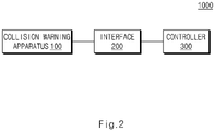
- FIG. 2 is a block diagram illustrating a configuration of a vehicle, according to an embodiment of the present disclosure.
- FIGS. 1 and 2 the configuration and operation of a vehicle 1000 will be described.
- the vehicle 1000 may be defined as an apparatus equipped with an autonomous driving technology that analyzes a collision risk between the vehicle 1000 and a surrounding object 2000 in front of the vehicle 1000 and provides a warning to pedestrians or brakes a vehicle based on the analysis result.
- the surrounding object 2000 may include, for example, a vulnerable road user (VRU) located in front of the vehicle 1000.
- VRU vulnerable road user
- the VRU may include a pedestrian or cyclist located on a road.
- the surrounding object 2000 may include an object capable of changing a moving direction or moving speed under the influence of the vehicle 1000 or the environment surrounding the vehicle.
- the vehicle 1000 may include a collision warning apparatus 100, an interface 200, and a controller 300.
- the collision warning apparatus 100 may recognize the surrounding object 2000 in front, and then may analyze the collision risk between the vehicle 1000 and the surrounding object 2000. For example, the collision warning apparatus 100 may generate collision prediction information of the surrounding object 2000 and then may provide a warning to the outside of the vehicle based on the collision prediction information; alternatively, while providing a warning outside the vehicle, the collision warning apparatus 100 may generate control information for controlling the braking of the vehicle.
- the collision warning apparatus 100 may obtain object information of the surrounding object 2000 and vehicle information.
- the object information may include a relative location and relative velocity of the surrounding object 2000.
- the vehicle information may include a size and angular velocity of the vehicle 1000.
- the collision warning apparatus 100 may generate the collision prediction information of the surrounding object 2000, based on the obtained vehicle information and the obtained object information of the surrounding object 2000.
- the collision warning apparatus 100 may generate a collision prediction location (y pred ), a time to collision (TTC Radial ) , and a collision risk ( ⁇ index ) of the surrounding object 2000, based on the relative location of the surrounding object 2000, the relative velocity of the surrounding object 2000, and the size and angular velocity of the vehicle 1000.
- the collision warning apparatus 100 may predict the collision prediction location (y pred ) of the surrounding object 2000 based on the relative location and relative velocity of the surrounding object 2000.
- the collision warning apparatus 100 may predict time to collision (TTC Radial ) based on the relative location of the surrounding object 2000 and an angle between the vehicle 1000 and the surrounding object 2000, and then may calculate a reciprocal (TTC Radial -1 ) of time to collision based on time to collision (TTC Radial ) .
- the collision warning apparatus 100 may predict a collision risk ( ⁇ index ) based on the collision prediction location (y pred ) of the surrounding object 2000.
- the collision warning apparatus 100 may provide a warning to the surrounding object 2000, or may generate control information for controlling the braking of the vehicle 1000 while providing a warning to the surrounding object 2000.
- the interface 200 may receive a warning mode of the vehicle 1000 from a user and may deliver information about the received warning mode. That is, the interface 200 may be a connection device or a communication device that connects the user to the vehicle 1000.
- the interface 200 may be a hardware device implemented by various electronic circuits, e.g., processor, transceiver, etc., to transmit and receive signals via wireless or wired connections.
- the interface 200 may receive the warning mode of the vehicle 1000 from the user.
- the warning mode may include at least one of a warning time point, whether an external warning of the vehicle 1000 is present, or whether the vehicle 1000 is braked.
- the warning time point may include, for example, an early mode, a normal mode or a late mode.
- an external warning of the vehicle 1000 may include at least one of an external horn on mode, an external horn off mode, an external lamp on mode, or an external lamp off mode.
- Whether the vehicle 1000 is braked may include a braking off mode or a braking on mode.
- the controller 300 may include an electronic control unit (ECU) of a vehicle that performs vehicle communication with the collision warning apparatus 100 through the interface 200 and then sets whether to generate a warning or whether to brake the vehicle 1000.
- ECU electronice control unit
- the controller 300 may provide a warning to the outside of the vehicle 1000, or may control the braking of the vehicle 1000 while providing a warning to the outside of the vehicle 1000.
- the control information obtained from the collision warning apparatus 100 may be information generated based on the collision prediction information.
- the warning provided to the outside of the vehicle 1000 may include at least one of a horn or a headlight beam.
- the controller 300 may provide a warning to the outside of the vehicle 1000.
- the controller 300 may control braking of the vehicle 1000 while providing a warning to the outside of the vehicle 1000.
- the controller 300 may provide a warning to the surrounding object 2000 or may control the braking of the vehicle 1000 while providing a warning to the surrounding object 2000.
- the controller 300 may provide a warning to the outside of the vehicle 1000.
- the first value may include ⁇ 2 .
- the first threshold time may be a reference time that is a criterion for whether to provide a warning to the outside of the vehicle 1000.
- the controller 300 may partially control braking of the vehicle 1000 while providing a warning to the outside of the vehicle 1000.
- the second value may include ⁇ 1 .
- the second threshold time may be a reference time that is a criterion for whether to provide braking of the vehicle 1000.
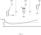
- FIG. 3 is a view for describing an operation of a surrounding object according to a collision warning of a vehicle, according to an embodiment of the present disclosure.
- the controller 300 of the vehicle 1000 may provide a warning to the outside of the vehicle 1000 and may partially control braking of the vehicle 1000.
- the vehicle 1000 may be designed to perform avoidance driving due to external warnings and partial braking, for the purpose of avoiding a collision.
- the controller 300 may fully brake the vehicle 1000.
- the second value may include ⁇ 1 .
- the second threshold time may be a reference time that is a criterion for whether to provide braking of the vehicle 1000.
- FIG. 4 is a view for describing an operation of a surrounding object according to a collision warning of a vehicle, according to another embodiment of the present disclosure.
- the controller 300 of the vehicle 1000 may partially control braking of the vehicle 1000 while providing a warning to the outside of the vehicle 1000.
- the vehicle 1000 may brake the vehicle 1000 to prevent a collision.
- FIG. 5 is a block diagram illustrating a configuration of a collision warning apparatus, according to an embodiment of the present disclosure.
- the collision warning apparatus 100 may include an information acquisition device 110 and a controller 120.
- the information acquisition device 110 may obtain vehicle information and information of the surrounding object 2000.
- the information acquisition device 110 may be a sensor (e.g., camera, radar, lidar, etc.) or a processor that is implemented by a non-transitory memory and programmed to perform information acquisition functions.
- the information acquisition device 110 may detect the surrounding object 2000 in front of the vehicle 1000 by using a front camera of the vehicle 1000.
- the information acquisition device 110 may detect the relative location and relative velocity of the surrounding object 2000 by using a radar or a lidar.
- the radar may obtain a distance to the surrounding object 2000.
- the radar may transmit a transmission electromagnetic wave signal to the surrounding object 2000 detected through the front camera, and then may receive reception electromagnetic waves reflected from the surrounding object 2000.
- the radar may obtain a distance to the surrounding object 2000, the relative location of the surrounding object 2000, and the relative velocity of the surrounding object 2000 by using a Doppler frequency change and a time difference between a transmission electromagnetic wave and a reception electromagnetic wave.
- the controller 120 may generate collision prediction information of the surrounding object 2000 based on vehicle information and information of the surrounding object 2000 obtained by the information acquisition device 110.
- the controller 120 may generate a collision prediction location (y pred ), a time to collision (TTC Radial ), and a collision risk ( ⁇ index ) of the surrounding object 2000, based on the relative location of the surrounding object 2000, the relative velocity of the surrounding object 2000, and the size and angular velocity of the vehicle 1000.
- the controller 120 may provide a warning to the outside of the vehicle 1000, or may generate control information for controlling the braking of the vehicle 1000 while providing a warning to the outside of the vehicle 1000.
- the controller 120 may deliver the control information to the controller 300.
- the controller 120 predicts a collision prediction location of the surrounding object 2000 based on a relative location and relative velocity of the surrounding object 2000.
- FIG. 6 is a view for describing that a collision warning apparatus predicts a collision prediction location, according to an embodiment of the present disclosure.
- the controller 120 may calculate a collision prediction location (y pred ) of the surrounding object 2000 based on Equation 1.
- y pred y ⁇ V rely V relx ⁇ x
- Equation 1 (x, y) denotes a relative location of the surrounding object 2000; (V relx , V rely ) denotes a relative velocity of the surrounding object 2000; and, “y pred " denotes a collision prediction location.
- the controller 120 may determine that the surrounding object 2000 is in danger of collision with the vehicle 1000.
- the controller 120 may differently set a threshold range depending on whether the surrounding object 2000 is located on one of the front, left or right side of the vehicle 1000.
- the threshold range may be divided into a left threshold and a right threshold of the vehicle 1000. That is, when the surrounding object 2000 is positioned between the left threshold and the right threshold of the vehicle 1000, the controller 120 may determine that the surrounding object 2000 is in danger of collision with the vehicle 1000.
- the controller 120 may calculate the threshold range based on Equation 2 below.
- Equation 2 (x, y) denotes a relative location of the surrounding object 2000; (V relx , V rely ) denotes a relative velocity of the surrounding object 2000; 'w' denotes a width of the vehicle 1000; and 'L' denotes a distance from a front end of the vehicle 1000 to an A-pillar of the vehicle 1000.
- z(x, y) may be defined as a variable used to determine whether the collision prediction location (y pred ) of the surrounding object 2000 is within a threshold range of the surrounding object 2000.
- the controller 120 may determine whether the collision prediction location (y pred ) of the surrounding object 2000 is within the threshold range of the surrounding object 2000, based on z(x, y).
- the controller 120 predicts the time to collision (TTC Radial ) based on a relative location of the surrounding object 2000 and an angle between the vehicle 1000 and the surrounding object 2000.
- FIG. 7 is a view for describing that a collision warning apparatus predicts a time to collision, according to an embodiment of the present disclosure.
- FIG. 8 is a diagram for describing a reciprocal of time to collision, according to an embodiment of the present disclosure.
- the controller 120 may calculate a reciprocal of time to collision based on a relative location (x, y) of the surrounding object 2000, a relative velocity (V relx , V rely ) of the surrounding object 2000, an angular velocity ( ⁇ yawrate ) of the vehicle 1000, and an angle ( ⁇ ) between the surrounding object 2000 and the vehicle 1000.
- the controller 120 may calculate the reciprocal (TTC Radial -1 ) of time to collision, which reflects the angular velocity ( ⁇ yawrate ) of the vehicle 1000 and the lateral movement of the surrounding object 2000, by using the angular velocity ( ⁇ yawrate ) of the vehicle 1000 and the angle ( ⁇ ) between the surrounding object 2000 and the vehicle 1000 that is radial information.
- the controller 120 may calculate the reciprocal (TTC Radial -1 ) of time to collision based on Equation 3 below.
- TTC Radial ⁇ 1 R ⁇ R + ⁇ ⁇ ⁇
- Equation 3 ⁇ denotes a value obtained by differentiating a distance R between the vehicle 1000 and the surrounding object 2000; (x, y) denotes a relative location of the surrounding object 2000; (V relx , V rely ) denotes a relative velocity of the surrounding object 2000; “ ⁇ yawrate " denotes an angular velocity of the vehicle 1000; and, ' ⁇ ' denotes an angle between the surrounding object 2000 and the vehicle 1000.
- FIG. 8 is a graph illustrating a relationship between time and a reciprocal (TTC Radial -1 ) of time to collision.
- point 1', '2' or '3' on the time axis is a point where the reciprocal (TTC Radial -1 ) of time to collision belongs to a danger area; and, point '4' on the time axis is a point where the reciprocal (TTC Radial -1 ) of time to collision belongs to a safe area.
- point '1', '2' or '3' on the time axis correspond to a case that the reciprocal (TTC Radial -1 ) of time to collision exceeds a reference value based on a specific reference value. Because the time to collision is shorter than the reference time, the collision risk between the vehicle 1000 and the surrounding object 2000 may be high.
- point '4' on the time axis correspond to a case that the reciprocal (TTC Radial -1 ) of time to collision less than the reference value based on the specific reference value. Because the time to collision is longer than the reference time, the collision risk between the vehicle 1000 and the surrounding object 2000 may be low.
- controller 120 may predict a collision risk ( ⁇ index ) based on the collision prediction location (y pred ) of the surrounding object 2000.
- the controller 120 may calculate the collision risk ( ⁇ index ) of the surrounding object 2000 based on Equation 4 below.
- r index 1 a y pred 2 + 1 b y ⁇ pred ⁇ y pred
- Equation 4 'y pred ' denotes a collision prediction location of the surrounding object 2000; ⁇ pred denotes a value obtained by differentiating y pred with respect to a time; and, 'a' and 'b' denote tuning variables.
- the controller 120 may calculate the collision risk ( ⁇ index ) by using a quadratic function of the collision prediction location (y pred ) of the surrounding object 2000.
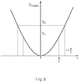
- FIG. 9 is a graph for describing a collision risk according to a collision prediction location, according to an embodiment of the present disclosure.
- FIG. 9 is a graph illustrating a collision risk ( ⁇ index ) when ⁇ pred is 0 in Equation 4.
- a collision risk ( ⁇ index ) is ⁇ 1 .
- the collision risk ( ⁇ index ) of ⁇ 1 means the collision risk at a point in time when the vehicle 1000 collides with the surrounding object 2000 within a width (L) of a front portion in front of the vehicle 1000.
- the collision risk ( ⁇ index ) between ⁇ 1 and ⁇ 2 means the collision risk ( ⁇ index ) at a point in time when the collision between the vehicle 1000 and the surrounding object 2000 is predicted within the A-pillar width on the side of the vehicle 1000.
- the controller 120 may provide a warning to the outside of the vehicle 1000, or may provide control information for controlling the braking of the vehicle 1000 while providing a warning to the outside of the vehicle 1000. That is, on the basis of the collision prediction location (y pred ), the reciprocal (TTC Radial -1 ) of time to collision, and the collision risk ( ⁇ index ) , the controller 120 may provide a warning to the surrounding object 2000, or may provide the control information for the controlling braking of the vehicle 1000 while providing a warning to the surrounding object 2000.
- the warning provided to the outside of the vehicle 1000 may include at least one of a horn or a headlight beam.
- the controller 300 of the vehicle 1000 and the controller 120 of the collision warning apparatus 100 may be a processor (e.g., computer, microprocessor, CPU, ASIC, circuitry, logic circuits, etc.).
- Each of the controller 300 and the controller 120 may be implemented by a non-transitory memory storing, e.g., a program(s), software instructions reproducing algorithms, etc., which, when executed, performs various functions described hereinafter, and a processor configured to execute the program(s), software instructions reproducing algorithms, etc.
- the memory and the processor may be implemented as separate semiconductor circuits.
- the memory and the processor may be implemented as a single integrated semiconductor circuit.
- the processor may embody one or more processor(s).
- the controller 300 and the controller 120 may include a communication module that is a hardware device implemented by various electronic circuits, e.g., processor, transceiver, etc., to transmit and receive signals via wireless or wired connections.
- the vehicle 1000 may provide an opportunity to avoid a collision by providing a warning to a pedestrian, thereby preventing a collision accident in advance.
- the vehicle 1000 may calculate the collision risk of the surrounding object 2000 and then may provide warnings classified depending on a collision risk. Accordingly, the vehicle 1000 may provide a collision avoidance system optimized for driving situations of a vehicle.
- the vehicle 1000 may reduce unnecessary braking action by analyzing collision risk, the vehicle 1000 may improve the fuel efficiency and may prevent sudden stops. Accordingly, the vehicle 1000 may improve the safety of a driver and passengers.
- a collision warning apparatus that may prevent collision accidents in advance by providing a warning to pedestrians and may provide a warning classified depending on a collision risk, and a vehicle including the same.
Landscapes
- Engineering & Computer Science (AREA)
- Mechanical Engineering (AREA)
- Transportation (AREA)
- Physics & Mathematics (AREA)
- Automation & Control Theory (AREA)
- Remote Sensing (AREA)
- Radar, Positioning & Navigation (AREA)
- General Physics & Mathematics (AREA)
- Computer Networks & Wireless Communication (AREA)
- Electromagnetism (AREA)
- Chemical & Material Sciences (AREA)
- Combustion & Propulsion (AREA)
- Acoustics & Sound (AREA)
- Mathematical Physics (AREA)
- Human Computer Interaction (AREA)
- Traffic Control Systems (AREA)
Abstract
Description
- This application claims the benefit of priority to
Korean Patent Application No. 10-2021-0086388, filed in the Korean Intellectual Property Office on July 1, 2021 - The present disclosure relates to a collision warning apparatus and a vehicle including the same.
- Vehicles equipped with an autonomous driving technology employ a collision avoidance system for preventing collisions between a vehicle and other objects such as pedestrians or cyclists on a road.
- A conventional collision avoidance system prevents collisions between vehicles and pedestrians or cyclists, by providing a vehicle driver with a warning sound, the vibration of a steering wheel, or a warning pop-up, or by providing the vehicle driver with vehicle braking or evasive steering.
- However, this collision avoidance system may not prevent a collision accident (i.e., a collision accident due to unexpected pedestrian movement) caused by careless pedestrians. In addition, it is impossible to prevent a collision accident due to a pedestrian's avoidance by providing the pedestrian with a warning in advance.
- The present disclosure has been made to solve the above-mentioned problems occurring in the prior art while advantages achieved by the prior art are maintained intact.
- An aspect of the present disclosure provides a collision warning apparatus that may prevent collision accidents in advance by providing a warning to pedestrians and may provide a warning classified depending on a collision risk, and a vehicle including the same.
- The technical problems to be solved by the present inventive concept are not limited to the aforementioned problems, and any other technical problems not mentioned herein will be clearly understood from the following description by those skilled in the art to which the present disclosure pertains.
- According to an aspect of the present disclosure, a collision warning apparatus of a vehicle may include an information acquisition device that obtains surrounding object information and vehicle information and a controller that generates collision prediction information of a surrounding object based on the surrounding object information and the vehicle information and provides a warning to an outside of the vehicle or generates control information for controlling braking of the vehicle while providing the warning to the outside of the vehicle based on the collision prediction information.
- According to an embodiment, the surrounding object information may include a relative location of the surrounding object and a relative velocity of the surrounding object with respect to a location and a velocity of the vehicle, respectively. The vehicle information may include a size of the vehicle and an angular velocity of the vehicle.
- According to an embodiment, the information acquisition device may detect the surrounding object in front of the vehicle by using a vehicle front camera, and may detect the relative location of the surrounding object and the relative velocity of the surrounding object by using a radar or a lidar.
- According to an embodiment, the collision prediction information may include a collision prediction location of the surrounding object, a time to collision of the surrounding object, and a collision risk of the surrounding object.
- According to an embodiment, the controller may predict the collision prediction location based on the relative location and the relative velocity, may predict the time to collision based on the relative location and an angle between the vehicle and the surrounding object, and may predict the collision risk based on the collision prediction location.
- According to an embodiment, the controller may provide the warning to the outside of the vehicle or may generate the control information for controlling the braking of the vehicle while providing to the outside of the vehicle, when the collision prediction location is within a threshold range from the vehicle.
- According to an embodiment, the controller may generate control information for providing a warning to the outside of the vehicle, when the collision risk is less than a first value and a reciprocal of the time to collision exceeds a first threshold time.
- According to an embodiment, the controller may generate the control information for controlling the braking of the vehicle while providing the warning to the outside of the vehicle when the collision risk is less than a second value and a reciprocal of the time to collision exceeds a second threshold time.
- According to an embodiment, the controller may generate control information for braking the vehicle, when the collision risk is not less than a second value and is less than a first value and a reciprocal of the time to collision exceeds a second threshold time.
- According to an embodiment, the warning provided to the outside of the vehicle may include at least one of a horn or a headlight beam.
- According to an aspect of the present disclosure, a vehicle may include an interface that receives a warning mode of the vehicle, a collision warning apparatus that obtains surrounding object information and vehicle information and generates collision prediction information of a surrounding object based on the surrounding object information and the vehicle information, and a vehicle controller that provides a warning to an outside of the vehicle or controls braking of the vehicle while providing the warning to the outside of the vehicle based on the collision prediction information and the warning mode received through the interface.
- According to an embodiment, the surrounding object information may include a relative location of the surrounding object and a relative velocity of the surrounding object with respect to a location and a velocity of the vehicle, respectively. The vehicle information may include a size of the vehicle and an angular velocity of the vehicle.
- According to an embodiment, the collision prediction information may include a collision prediction location of the surrounding object, a time to collision of the surrounding object, and a collision risk of the surrounding object.
- According to an embodiment, the warning mode may include at least one of a warning time point, whether an external warning of the vehicle is present, or whether the vehicle is braked.
- According to an embodiment, the collision warning apparatus may predict the collision prediction location based on the relative location and the relative velocity, may predict the time to collision based on the relative location and an angle between the vehicle and the surrounding object, and may predict the collision risk based on the collision prediction location.
- According to an embodiment, the vehicle controller may provide the warning to the outside of the vehicle or may control the braking of the vehicle while providing the warning to the outside of the vehicle when the warning mode includes execution of an external warning of the vehicle and execution of the braking of the vehicle, and the collision prediction location is within a threshold range from the vehicle.
- According to an embodiment, the vehicle controller may provide the warning to the outside of the vehicle, when the collision risk is less than a first value and a reciprocal of the time to collision exceeds a first threshold time.
- According to an embodiment, the vehicle controller may control the braking of the vehicle while providing the warning to the outside of the vehicle when the collision risk is less than a second value and a reciprocal of the time to collision exceeds a second threshold time.
- According to an embodiment, the vehicle controller may brake the vehicle, when the collision risk is not less than a second value and is less than a first value and a reciprocal of the time to collision exceeds a second threshold time.
- According to an embodiment, the warning provided to the outside of the vehicle may include at least one of a horn or a headlight beam.
- The above and other objects, features and advantages of the present disclosure will be more apparent from the following detailed description taken in conjunction with the accompanying drawings:
-
FIG. 1 is a view for describing generally a vehicle, according to an embodiment of the present disclosure; -
FIG. 2 is a block diagram illustrating a configuration of a vehicle, according to an embodiment of the present disclosure; -
FIG. 3 is a view for describing an operation of a surrounding object according to a collision warning of a vehicle, according to an embodiment of the present disclosure; -
FIG. 4 is a view for describing an operation of a surrounding object according to a collision warning of a vehicle, according to another embodiment of the present disclosure; -
FIG. 5 is a block diagram illustrating a configuration of a collision warning apparatus, according to an embodiment of the present disclosure; -
FIG. 6 is a view for describing that a collision warning apparatus predicts a collision prediction location, according to an embodiment of the present disclosure; -
FIG. 7 is a view for describing that a collision warning apparatus predicts a time to collision, according to an embodiment of the present disclosure; -
FIG. 8 is a diagram for describing a reciprocal of time to collision, according to an embodiment of the present disclosure; and -
FIG. 9 is a graph for describing a collision risk according to a collision prediction location, according to an embodiment of the present disclosure. - Hereinafter, exemplary embodiments of the present disclosure will be described in detail with reference to the accompanying drawings. In adding reference numerals to components of each drawing, it should be noted that the same components have the same reference numerals, although they are indicated on another drawing. In describing the embodiments of the present disclosure, detailed descriptions associated with well-known functions or configurations will be omitted when they may make subject matters of the present disclosure unnecessarily obscure.
- In describing elements of exemplary embodiments of the present disclosure, the terms first, second, A, B, (a), (b), and the like may be used herein. These terms are only used to distinguish one element from another element, but do not limit the corresponding elements irrespective of the nature, order, or priority of the corresponding elements. Furthermore, unless otherwise defined, all terms including technical and scientific terms used herein are to be interpreted as is customary in the art to which the present disclosure belongs. It will be understood that terms used herein should be interpreted as having a meaning that is consistent with their meaning in the context of the present disclosure and the relevant art and will not be interpreted in an idealized or overly formal sense unless expressly so defined herein.
-
FIG. 1 is a view for describing generally a vehicle, according to an embodiment of the present disclosure.FIG. 2 is a block diagram illustrating a configuration of a vehicle, according to an embodiment of the present disclosure. - Hereinafter, referring to
FIGS. 1 and2 , the configuration and operation of avehicle 1000 will be described. - Referring to
FIG. 1 , thevehicle 1000 may be defined as an apparatus equipped with an autonomous driving technology that analyzes a collision risk between thevehicle 1000 and a surroundingobject 2000 in front of thevehicle 1000 and provides a warning to pedestrians or brakes a vehicle based on the analysis result. - Herein, the surrounding
object 2000 may include, for example, a vulnerable road user (VRU) located in front of thevehicle 1000. The VRU may include a pedestrian or cyclist located on a road. The surroundingobject 2000 may include an object capable of changing a moving direction or moving speed under the influence of thevehicle 1000 or the environment surrounding the vehicle. - Referring to
FIG. 2 , thevehicle 1000 may include acollision warning apparatus 100, aninterface 200, and acontroller 300. - The
collision warning apparatus 100 may recognize the surroundingobject 2000 in front, and then may analyze the collision risk between thevehicle 1000 and the surroundingobject 2000. For example, thecollision warning apparatus 100 may generate collision prediction information of the surroundingobject 2000 and then may provide a warning to the outside of the vehicle based on the collision prediction information; alternatively, while providing a warning outside the vehicle, thecollision warning apparatus 100 may generate control information for controlling the braking of the vehicle. - The
collision warning apparatus 100 may obtain object information of the surroundingobject 2000 and vehicle information. Herein, the object information may include a relative location and relative velocity of the surroundingobject 2000. The vehicle information may include a size and angular velocity of thevehicle 1000. - The
collision warning apparatus 100 may generate the collision prediction information of the surroundingobject 2000, based on the obtained vehicle information and the obtained object information of the surroundingobject 2000. - In detail, the
collision warning apparatus 100 may generate a collision prediction location (ypred), a time to collision (TTCRadial) , and a collision risk (γindex) of the surroundingobject 2000, based on the relative location of the surroundingobject 2000, the relative velocity of the surroundingobject 2000, and the size and angular velocity of thevehicle 1000. - The
collision warning apparatus 100 may predict the collision prediction location (ypred) of the surroundingobject 2000 based on the relative location and relative velocity of the surroundingobject 2000. - Furthermore, the
collision warning apparatus 100 may predict time to collision (TTCRadial) based on the relative location of the surroundingobject 2000 and an angle between thevehicle 1000 and the surroundingobject 2000, and then may calculate a reciprocal (TTCRadial -1) of time to collision based on time to collision (TTCRadial) . - Moreover, the
collision warning apparatus 100 may predict a collision risk (γindex) based on the collision prediction location (ypred) of the surroundingobject 2000. - On the basis of the collision prediction location (ypred), the reciprocal (TTCRadial -1) of time to collision, and the collision risk (γindex), the
collision warning apparatus 100 may provide a warning to the surroundingobject 2000, or may generate control information for controlling the braking of thevehicle 1000 while providing a warning to the surroundingobject 2000. - The
interface 200 may receive a warning mode of thevehicle 1000 from a user and may deliver information about the received warning mode. That is, theinterface 200 may be a connection device or a communication device that connects the user to thevehicle 1000. For example, theinterface 200 may be a hardware device implemented by various electronic circuits, e.g., processor, transceiver, etc., to transmit and receive signals via wireless or wired connections. - The
interface 200 may receive the warning mode of thevehicle 1000 from the user. Herein, the warning mode may include at least one of a warning time point, whether an external warning of thevehicle 1000 is present, or whether thevehicle 1000 is braked. - The warning time point may include, for example, an early mode, a normal mode or a late mode. Whether an external warning of the
vehicle 1000 is present may include at least one of an external horn on mode, an external horn off mode, an external lamp on mode, or an external lamp off mode. Whether thevehicle 1000 is braked may include a braking off mode or a braking on mode. - The
controller 300 may include an electronic control unit (ECU) of a vehicle that performs vehicle communication with thecollision warning apparatus 100 through theinterface 200 and then sets whether to generate a warning or whether to brake thevehicle 1000. - On the basis of the control information obtained from the
collision warning apparatus 100 and the warning mode input through theinterface 200, thecontroller 300 may provide a warning to the outside of thevehicle 1000, or may control the braking of thevehicle 1000 while providing a warning to the outside of thevehicle 1000. For example, the control information obtained from thecollision warning apparatus 100 may be information generated based on the collision prediction information. Herein, the warning provided to the outside of thevehicle 1000 may include at least one of a horn or a headlight beam. - For example, when the warning mode received through the
interface 200 includes at least one of the external horn on mode or the external lamp on mode, and the collision prediction location is within a threshold range, thecontroller 300 may provide a warning to the outside of thevehicle 1000. - For example, when the warning mode received through the
interface 200 includes at least one of the external horn on mode or the external lamp on mode, and includes the braking on mode, and when the collision prediction location is within the threshold range, thecontroller 300 may control braking of thevehicle 1000 while providing a warning to the outside of thevehicle 1000. - In detail, on the basis of the collision prediction location (ypred), the reciprocal (TTCRadial -1) of time to collision and the collision risk (γindex), the
controller 300 may provide a warning to the surroundingobject 2000 or may control the braking of thevehicle 1000 while providing a warning to the surroundingobject 2000. - When the collision risk (γindex) is less than a first value, and the reciprocal (TTCRadial -1) of time to collision exceeds a first threshold time, the
controller 300 may provide a warning to the outside of thevehicle 1000. Herein, the first value may include γ2. The first threshold time may be a reference time that is a criterion for whether to provide a warning to the outside of thevehicle 1000. - When the collision risk (γindex) is less than a second value and the reciprocal (TTCRadial -1) of time to collision exceeds a second threshold time, the
controller 300 may partially control braking of thevehicle 1000 while providing a warning to the outside of thevehicle 1000. Herein, the second value may include γ1. The second threshold time may be a reference time that is a criterion for whether to provide braking of thevehicle 1000. -
FIG. 3 is a view for describing an operation of a surrounding object according to a collision warning of a vehicle, according to an embodiment of the present disclosure. - Referring to
FIG. 3 , when the collision risk (γindex) of the surroundingobject 2000 is not less than the second value and less than the first value, thecontroller 300 of thevehicle 1000 may provide a warning to the outside of thevehicle 1000 and may partially control braking of thevehicle 1000. Thevehicle 1000 may be designed to perform avoidance driving due to external warnings and partial braking, for the purpose of avoiding a collision. - When the collision risk (γindex) is less than the second value, and the reciprocal (TTCRadial -1) of time to collision exceeds a second threshold time, the
controller 300 may fully brake thevehicle 1000. Herein, the second value may include γ1. Besides, the second threshold time may be a reference time that is a criterion for whether to provide braking of thevehicle 1000. -
FIG. 4 is a view for describing an operation of a surrounding object according to a collision warning of a vehicle, according to another embodiment of the present disclosure. - Referring to
FIG. 4 , when the collision risk (γindex) of the surroundingobject 2000 is not less than the second value and less than the first value, thecontroller 300 of thevehicle 1000 may partially control braking of thevehicle 1000 while providing a warning to the outside of thevehicle 1000. After the avoidance driving due to external warnings and partial braking is designed, when the collision risk (γindex) of the surroundingobject 2000 is less than the second value, thevehicle 1000 may brake thevehicle 1000 to prevent a collision. - Hereinafter, a configuration and operation of the
collision warning apparatus 100, which generates the collision prediction location, time to collision, and collision risk of the surroundingobject 2000 will be described in detail with reference toFIG. 5 . -
FIG. 5 is a block diagram illustrating a configuration of a collision warning apparatus, according to an embodiment of the present disclosure. - Referring to
FIG. 5 , thecollision warning apparatus 100 may include aninformation acquisition device 110 and acontroller 120. - The
information acquisition device 110 may obtain vehicle information and information of the surroundingobject 2000. Theinformation acquisition device 110 may be a sensor (e.g., camera, radar, lidar, etc.) or a processor that is implemented by a non-transitory memory and programmed to perform information acquisition functions. - For example, the
information acquisition device 110 may detect the surroundingobject 2000 in front of thevehicle 1000 by using a front camera of thevehicle 1000. - Furthermore, for example, the
information acquisition device 110 may detect the relative location and relative velocity of the surroundingobject 2000 by using a radar or a lidar. For example, the radar may obtain a distance to the surroundingobject 2000. The radar may transmit a transmission electromagnetic wave signal to the surroundingobject 2000 detected through the front camera, and then may receive reception electromagnetic waves reflected from the surroundingobject 2000. The radar may obtain a distance to the surroundingobject 2000, the relative location of the surroundingobject 2000, and the relative velocity of the surroundingobject 2000 by using a Doppler frequency change and a time difference between a transmission electromagnetic wave and a reception electromagnetic wave. - The
controller 120 may generate collision prediction information of the surroundingobject 2000 based on vehicle information and information of the surroundingobject 2000 obtained by theinformation acquisition device 110. In detail, thecontroller 120 may generate a collision prediction location (ypred), a time to collision (TTCRadial), and a collision risk (γindex) of the surroundingobject 2000, based on the relative location of the surroundingobject 2000, the relative velocity of the surroundingobject 2000, and the size and angular velocity of thevehicle 1000. - On the basis of the collision prediction information, the
controller 120 may provide a warning to the outside of thevehicle 1000, or may generate control information for controlling the braking of thevehicle 1000 while providing a warning to the outside of thevehicle 1000. Thecontroller 120 may deliver the control information to thecontroller 300. - Hereinafter, it will be described that the
controller 120 predicts a collision prediction location of the surroundingobject 2000 based on a relative location and relative velocity of the surroundingobject 2000. -
FIG. 6 is a view for describing that a collision warning apparatus predicts a collision prediction location, according to an embodiment of the present disclosure. - Referring to
FIG. 6 , thecontroller 120 may calculate a collision prediction location (ypred) of the surroundingobject 2000 based onEquation 1.
- In
Equation 1, (x, y) denotes a relative location of the surroundingobject 2000; (Vrelx, Vrely) denotes a relative velocity of the surroundingobject 2000; and, "ypred" denotes a collision prediction location. - When the collision prediction location (ypred) of the surrounding
object 2000 is included in a threshold range, thecontroller 120 may determine that the surroundingobject 2000 is in danger of collision with thevehicle 1000. - Herein, the
controller 120 may differently set a threshold range depending on whether the surroundingobject 2000 is located on one of the front, left or right side of thevehicle 1000. The threshold range may be divided into a left threshold and a right threshold of thevehicle 1000. That is, when the surroundingobject 2000 is positioned between the left threshold and the right threshold of thevehicle 1000, thecontroller 120 may determine that the surroundingobject 2000 is in danger of collision with thevehicle 1000. - The
controller 120 may calculate the threshold range based onEquation 2 below.
- * When the surrounding
object 2000 is positioned on a left side of thevehicle 1000, left threshold = -W/2, and right threshold = z(x, y) + W/2. - * When the surrounding
object 2000 is positioned on a right side of thevehicle 1000, left threshold = z(x, y) - (W/2), and right threshold = W/2. - * When the surrounding
object 2000 is located in front of thevehicle 1000, left threshold = -W/2, and right threshold = W/2. - In
Equation 2, (x, y) denotes a relative location of the surroundingobject 2000; (Vrelx, Vrely) denotes a relative velocity of the surroundingobject 2000; 'w' denotes a width of thevehicle 1000; and 'L' denotes a distance from a front end of thevehicle 1000 to an A-pillar of thevehicle 1000. - Herein, z(x, y) may be defined as a variable used to determine whether the collision prediction location (ypred) of the surrounding
object 2000 is within a threshold range of the surroundingobject 2000. Thecontroller 120 may determine whether the collision prediction location (ypred) of the surroundingobject 2000 is within the threshold range of the surroundingobject 2000, based on z(x, y). - Hereinafter, it is described that the
controller 120 predicts the time to collision (TTCRadial) based on a relative location of the surroundingobject 2000 and an angle between thevehicle 1000 and the surroundingobject 2000. -
FIG. 7 is a view for describing that a collision warning apparatus predicts a time to collision, according to an embodiment of the present disclosure.FIG. 8 is a diagram for describing a reciprocal of time to collision, according to an embodiment of the present disclosure. - First of all, referring to
FIG. 7 , thecontroller 120 may calculate a reciprocal of time to collision based on a relative location (x, y) of the surroundingobject 2000, a relative velocity (Vrelx, Vrely) of the surroundingobject 2000, an angular velocity (γyawrate) of thevehicle 1000, and an angle (θ) between the surroundingobject 2000 and thevehicle 1000. That is, thecontroller 120 may calculate the reciprocal (TTCRadial -1) of time to collision, which reflects the angular velocity (γyawrate) of thevehicle 1000 and the lateral movement of the surroundingobject 2000, by using the angular velocity (γyawrate) of thevehicle 1000 and the angle (θ) between the surroundingobject 2000 and thevehicle 1000 that is radial information. - The
controller 120 may calculate the reciprocal (TTCRadial -1) of time to collision based onEquation 3 below.
- In
Equation 3, Ṙ denotes a value obtained by differentiating a distance R between thevehicle 1000 and the surroundingobject 2000; (x, y) denotes a relative location of the surroundingobject 2000; (Vrelx, Vrely) denotes a relative velocity of the surroundingobject 2000; "γyawrate" denotes an angular velocity of thevehicle 1000; and, 'θ' denotes an angle between the surroundingobject 2000 and thevehicle 1000. -
FIG. 8 is a graph illustrating a relationship between time and a reciprocal (TTCRadial -1) of time to collision. InFIG. 8 , point 1', '2' or '3' on the time axis is a point where the reciprocal (TTCRadial -1) of time to collision belongs to a danger area; and, point '4' on the time axis is a point where the reciprocal (TTCRadial -1) of time to collision belongs to a safe area. - That is, point '1', '2' or '3' on the time axis correspond to a case that the reciprocal (TTCRadial -1) of time to collision exceeds a reference value based on a specific reference value. Because the time to collision is shorter than the reference time, the collision risk between the
vehicle 1000 and the surroundingobject 2000 may be high. - That is, point '4' on the time axis correspond to a case that the reciprocal (TTCRadial -1) of time to collision less than the reference value based on the specific reference value. Because the time to collision is longer than the reference time, the collision risk between the
vehicle 1000 and the surroundingobject 2000 may be low. - Furthermore, the
controller 120 may predict a collision risk (γindex) based on the collision prediction location (ypred) of the surroundingobject 2000. - The
controller 120 may calculate the collision risk (γindex) of the surroundingobject 2000 based onEquation 4 below.
- In
Equation 4, 'ypred' denotes a collision prediction location of the surroundingobject 2000; ẏpred denotes a value obtained by differentiating ypred with respect to a time; and, 'a' and 'b' denote tuning variables. Thecontroller 120 may calculate the collision risk (γindex) by using a quadratic function of the collision prediction location (ypred) of the surroundingobject 2000. -
FIG. 9 is a graph for describing a collision risk according to a collision prediction location, according to an embodiment of the present disclosure. In detail,FIG. 9 is a graph illustrating a collision risk (γindex) when ẏpred is 0 inEquation 4. - In
FIG. 9 , when the y-coordinate of the surroundingobject 2000, which is a relative location, is w/2, a collision risk (γindex) is γ1. When the y-coordinate of the surroundingobject 2000, which is the relative location, is "z + (W/2)", the collision risk (γindex) is γ2. Herein, the collision risk (γindex) of γ1 means the collision risk at a point in time when thevehicle 1000 collides with the surroundingobject 2000 within a width (L) of a front portion in front of thevehicle 1000. The collision risk (γindex) between γ1 and γ2 means the collision risk (γindex) at a point in time when the collision between thevehicle 1000 and the surroundingobject 2000 is predicted within the A-pillar width on the side of thevehicle 1000. - On the basis of the collision prediction information, the
controller 120 may provide a warning to the outside of thevehicle 1000, or may provide control information for controlling the braking of thevehicle 1000 while providing a warning to the outside of thevehicle 1000. That is, on the basis of the collision prediction location (ypred), the reciprocal (TTCRadial -1) of time to collision, and the collision risk (γindex) , thecontroller 120 may provide a warning to the surroundingobject 2000, or may provide the control information for the controlling braking of thevehicle 1000 while providing a warning to the surroundingobject 2000. Herein, the warning provided to the outside of thevehicle 1000 may include at least one of a horn or a headlight beam. - The
controller 300 of thevehicle 1000 and thecontroller 120 of thecollision warning apparatus 100 according to an exemplary embodiment of the present disclosure may be a processor (e.g., computer, microprocessor, CPU, ASIC, circuitry, logic circuits, etc.). Each of thecontroller 300 and thecontroller 120 may be implemented by a non-transitory memory storing, e.g., a program(s), software instructions reproducing algorithms, etc., which, when executed, performs various functions described hereinafter, and a processor configured to execute the program(s), software instructions reproducing algorithms, etc. Herein, the memory and the processor may be implemented as separate semiconductor circuits. Alternatively, the memory and the processor may be implemented as a single integrated semiconductor circuit. The processor may embody one or more processor(s). Thecontroller 300 and thecontroller 120 may include a communication module that is a hardware device implemented by various electronic circuits, e.g., processor, transceiver, etc., to transmit and receive signals via wireless or wired connections. - As described above, the
vehicle 1000 according to an embodiment of the present disclosure may provide an opportunity to avoid a collision by providing a warning to a pedestrian, thereby preventing a collision accident in advance. - Moreover, the
vehicle 1000 may calculate the collision risk of the surroundingobject 2000 and then may provide warnings classified depending on a collision risk. Accordingly, thevehicle 1000 may provide a collision avoidance system optimized for driving situations of a vehicle. - Besides, because the
vehicle 1000 may reduce unnecessary braking action by analyzing collision risk, thevehicle 1000 may improve the fuel efficiency and may prevent sudden stops. Accordingly, thevehicle 1000 may improve the safety of a driver and passengers. - Hereinabove, although the present disclosure has been described with reference to exemplary embodiments and the accompanying drawings, the present disclosure is not limited thereto, but may be variously modified and altered by those skilled in the art to which the present disclosure pertains without departing from the spirit and scope of the present disclosure claimed in the following claims.
- Therefore, embodiments of the present disclosure are not intended to limit the technical spirit of the present disclosure, but provided only for the illustrative purpose. The scope of protection of the present disclosure should be construed by the attached claims, and all equivalents thereof should be construed as being included within the scope of the present disclosure.
- According to an embodiment of the present disclosure, a collision warning apparatus that may prevent collision accidents in advance by providing a warning to pedestrians and may provide a warning classified depending on a collision risk, and a vehicle including the same.
- Hereinabove, although the present disclosure has been described with reference to exemplary embodiments and the accompanying drawings, the present disclosure is not limited thereto, but may be variously modified and altered by those skilled in the art to which the present disclosure pertains without departing from the spirit and scope of the present disclosure claimed in the following claims.
Claims (15)
- A collision warning apparatus of a vehicle, the apparatus comprising:an information acquisition device configured to obtain surrounding object information and vehicle information; anda controller configured to:generate collision prediction information of a surrounding object based on the surrounding object information and the vehicle information; andbased on the collision prediction information, provide a warning to an outside of the vehicle or generate control information for controlling braking of the vehicle while providing the warning to the outside of the vehicle.
- The apparatus of claim 1, wherein the surrounding object information includes a relative location of the surrounding object and a relative velocity of the surrounding object with respect to a location and a velocity of the vehicle, respectively, and
wherein the vehicle information includes a size of the vehicle and an angular velocity of the vehicle. - The apparatus of claim 2, wherein the information acquisition device detects the surrounding object in front of the vehicle by using a vehicle front camera, and detects the relative location of the surrounding object and the relative velocity of the surrounding object by using a radar or a lidar.
- The apparatus of claim 2, wherein the collision prediction information includes a collision prediction location of the surrounding object, a time to collision of the surrounding object, and a collision risk of the surrounding object.
- The apparatus of claim 4, wherein the controller predicts the collision prediction location based on the relative location and the relative velocity, predicts the time to collision based on the relative location and an angle between the vehicle and the surrounding object, and predicts the collision risk based on the collision prediction location.
- The apparatus of claim 4, wherein the controller provides the warning to the outside of the vehicle or generates the control information for controlling the braking of the vehicle while providing to the outside of the vehicle, when the collision prediction location is within a threshold range from the vehicle.
- The apparatus of claim 6, wherein the controller generates control information for providing the warning to the outside of the vehicle, when the collision risk is less than a first value and a reciprocal of the time to collision exceeds a first threshold time.
- The apparatus of claim 6, wherein the controller generates the control information for controlling the braking of the vehicle while providing the warning to the outside of the vehicle, when the collision risk is less than a second value and a reciprocal of the time to collision exceeds a second threshold time.
- The apparatus of claim 6, wherein the controller generates the control information for controlling the braking of the vehicle, when the collision risk is not less than a second value and is less than a first value and a reciprocal of the time to collision exceeds a second threshold time.
- The apparatus of claim 1, wherein the warning provided to the outside of the vehicle includes at least one of a horn or a headlight beam.
- A vehicle comprising:an interface configured to receive a warning mode of the vehicle;a collision warning apparatus configured to obtain surrounding object information and vehicle information and to generate collision prediction information of a surrounding object based on the surrounding object information and the vehicle information; anda vehicle controller configured to:based on the collision prediction information and the warning mode received through the interface,provide a warning to an outside of the vehicle; orcontrol braking of the vehicle while providing the warning to the outside of the vehicle.
- The method of claim 11, wherein the surrounding object information includes a relative location of the surrounding object and a relative velocity of the surrounding object with respect to a location and a velocity of the vehicle, respectively, and
wherein the vehicle information includes a size of the vehicle and an angular velocity of the vehicle. - The method of claim 12, wherein the collision prediction information includes a collision prediction location of the surrounding object, a time to collision of the surrounding object, and a collision risk of the surrounding object.
- The method of claim 13, wherein the warning mode includes at least one of a warning time point, whether an external warning of the vehicle is present, or whether the vehicle is braked.
- The method of claim 14, wherein the collision warning apparatus predicts the collision prediction location based on the relative location and the relative velocity, predicts the time to collision based on the relative location and an angle between the vehicle and the surrounding object, and predicts the collision risk based on the collision prediction location.
Applications Claiming Priority (1)
| Application Number | Priority Date | Filing Date | Title |
|---|---|---|---|
| KR1020210086388A KR102592665B1 (en) | 2021-07-01 | 2021-07-01 | Apparatus for collision waring and vehicle including the same |
Publications (1)
| Publication Number | Publication Date |
|---|---|
| EP4113479A1 true EP4113479A1 (en) | 2023-01-04 |
Family
ID=80930258
Family Applications (1)
| Application Number | Title | Priority Date | Filing Date |
|---|---|---|---|
| EP22163333.2A Pending EP4113479A1 (en) | 2021-07-01 | 2022-03-21 | Apparatus for collision warning and vehicle including the same |
Country Status (4)
| Country | Link |
|---|---|
| US (1) | US20230003875A1 (en) |
| EP (1) | EP4113479A1 (en) |
| KR (1) | KR102592665B1 (en) |
| CN (1) | CN115556666A (en) |
Citations (5)
| Publication number | Priority date | Publication date | Assignee | Title |
|---|---|---|---|---|
| US20160075332A1 (en) * | 2014-09-17 | 2016-03-17 | Magna Electronics Inc. | Vehicle collision avoidance system with enhanced pedestrian avoidance |
| US20180118106A1 (en) * | 2016-11-01 | 2018-05-03 | Hyundai Motor Company | Vehicle and control method thereof |
| US20180162388A1 (en) * | 2016-12-13 | 2018-06-14 | Hyundai Motor Company | Apparatus for preventing pedestrian collision accident, system having the same, and method thereof |
| US20180233048A1 (en) * | 2015-08-20 | 2018-08-16 | Scania Cv Ab | Method, control unit and system for avoiding collision with vulnerable road users |
| US20190180624A1 (en) * | 2016-10-19 | 2019-06-13 | Novateur Research Solutions LLC | Pedestrian side collision warning systems and methods |
Family Cites Families (10)
| Publication number | Priority date | Publication date | Assignee | Title |
|---|---|---|---|---|
| JP2007047953A (en) * | 2005-08-09 | 2007-02-22 | Hitachi Ltd | Controller for vehicle and vehicle alarm system |
| JP4732371B2 (en) * | 2007-01-12 | 2011-07-27 | 富士通テン株式会社 | Perimeter monitoring device and perimeter monitoring method |
| JP5316549B2 (en) * | 2009-01-29 | 2013-10-16 | トヨタ自動車株式会社 | Object recognition apparatus and object recognition method |
| JP4706984B2 (en) * | 2009-02-25 | 2011-06-22 | トヨタ自動車株式会社 | Collision estimation apparatus and collision estimation method |
| JP2015141553A (en) * | 2014-01-29 | 2015-08-03 | クラリオン株式会社 | Risk avoidance control device, risk avoidance control method, and program |
| US20150329043A1 (en) * | 2014-05-13 | 2015-11-19 | Continental Automotive Systems, Inc. | Warning to a Pedestrian in Dangerous Situation |
| JP6565893B2 (en) * | 2016-12-26 | 2019-08-28 | トヨタ自動車株式会社 | Driving assistance device |
| KR20200051085A (en) * | 2018-11-02 | 2020-05-13 | 현대자동차주식회사 | Vehicle and control method for the same |
| JP7258653B2 (en) * | 2019-05-23 | 2023-04-17 | 日本車輌製造株式会社 | Pile driver safety system |
| DE102019215863A1 (en) * | 2019-10-15 | 2021-04-15 | Continental Automotive Gmbh | Vehicle, comprising a turning assistance device, turning assistance device and method for operating a vehicle |
-
2021
- 2021-07-01 KR KR1020210086388A patent/KR102592665B1/en active IP Right Grant
-
2022
- 2022-03-21 EP EP22163333.2A patent/EP4113479A1/en active Pending
- 2022-03-24 US US17/703,274 patent/US20230003875A1/en active Pending
- 2022-04-15 CN CN202210394889.0A patent/CN115556666A/en active Pending
Patent Citations (5)
| Publication number | Priority date | Publication date | Assignee | Title |
|---|---|---|---|---|
| US20160075332A1 (en) * | 2014-09-17 | 2016-03-17 | Magna Electronics Inc. | Vehicle collision avoidance system with enhanced pedestrian avoidance |
| US20180233048A1 (en) * | 2015-08-20 | 2018-08-16 | Scania Cv Ab | Method, control unit and system for avoiding collision with vulnerable road users |
| US20190180624A1 (en) * | 2016-10-19 | 2019-06-13 | Novateur Research Solutions LLC | Pedestrian side collision warning systems and methods |
| US20180118106A1 (en) * | 2016-11-01 | 2018-05-03 | Hyundai Motor Company | Vehicle and control method thereof |
| US20180162388A1 (en) * | 2016-12-13 | 2018-06-14 | Hyundai Motor Company | Apparatus for preventing pedestrian collision accident, system having the same, and method thereof |
Also Published As
| Publication number | Publication date |
|---|---|
| CN115556666A (en) | 2023-01-03 |
| KR102592665B1 (en) | 2023-10-24 |
| KR20230005543A (en) | 2023-01-10 |
| US20230003875A1 (en) | 2023-01-05 |
Similar Documents
| Publication | Publication Date | Title |
|---|---|---|
| CN106985780B (en) | Vehicle safety auxiliary system | |
| CN111137281B (en) | Vehicle and control method for vehicle | |
| KR20200102004A (en) | Apparatus, system and method for preventing collision | |
| US11427166B2 (en) | Adaptive AEB system considering steerable path and control method thereof | |
| EP3354525B1 (en) | Arrangement and method for mitigating a forward collision between road vehicles | |
| JP5953716B2 (en) | Vehicle control apparatus, specific object determination apparatus, specific object determination method, specific object determination program | |
| US10745008B2 (en) | Driving support device and driving support method | |
| EP2484573A1 (en) | Method for reducing the risk of a collision between a vehicle and a first external object | |
| US9771055B1 (en) | Front impact mitigation system for a vehicle and method | |
| EP3683112B1 (en) | Collision avoidance control apparatus | |
| US11872983B2 (en) | Vehicle collision prediction apparatus | |
| KR20130139928A (en) | Method and system for reducing a reaction delay time of a vehicle safety control device | |
| US20190092320A1 (en) | Vehicle control device | |
| US11305761B2 (en) | Collision avoidance control apparatus | |
| CN112277937A (en) | Collision avoidance aid | |
| WO2019012995A1 (en) | Driving support device | |
| KR20200095976A (en) | driver assistance apparatus | |
| JP2008152390A (en) | Periphery-monitoring device for vehicle | |
| CN113544031A (en) | Driving support device | |
| EP4113479A1 (en) | Apparatus for collision warning and vehicle including the same | |
| Chen et al. | Safe technology with a novel rear collision avoidance system of vehicles | |
| JP2008143429A (en) | Collision predicting device | |
| KR20230005556A (en) | Apparatus for collision waring and vehicle including the same | |
| US20200174134A1 (en) | Object recognition via indirect signal reflection | |
| US20240239314A1 (en) | Vehicle control apparatus |
Legal Events
| Date | Code | Title | Description |
|---|---|---|---|
| PUAI | Public reference made under article 153(3) epc to a published international application that has entered the european phase |
Free format text: ORIGINAL CODE: 0009012 |
|
| STAA | Information on the status of an ep patent application or granted ep patent |
Free format text: STATUS: REQUEST FOR EXAMINATION WAS MADE |
|
| 17P | Request for examination filed |
Effective date: 20220321 |
|
| AK | Designated contracting states |
Kind code of ref document: A1 Designated state(s): AL AT BE BG CH CY CZ DE DK EE ES FI FR GB GR HR HU IE IS IT LI LT LU LV MC MK MT NL NO PL PT RO RS SE SI SK SM TR |
|
| RBV | Designated contracting states (corrected) |
Designated state(s): AL AT BE BG CH CY CZ DE DK EE ES FI FR GB GR HR HU IE IS IT LI LT LU LV MC MK MT NL NO PL PT RO RS SE SI SK SM TR |
|
| STAA | Information on the status of an ep patent application or granted ep patent |
Free format text: STATUS: EXAMINATION IS IN PROGRESS |
|
| 17Q | First examination report despatched |
Effective date: 20240315 |