EP2151175A2 - Beer table or sitting bench - Google Patents
Beer table or sitting bench Download PDFInfo
- Publication number
- EP2151175A2 EP2151175A2 EP20090010042 EP09010042A EP2151175A2 EP 2151175 A2 EP2151175 A2 EP 2151175A2 EP 20090010042 EP20090010042 EP 20090010042 EP 09010042 A EP09010042 A EP 09010042A EP 2151175 A2 EP2151175 A2 EP 2151175A2
- Authority
- EP
- European Patent Office
- Prior art keywords
- plate
- halves
- plate halves
- pivoting
- support
- Prior art date
- Legal status (The legal status is an assumption and is not a legal conclusion. Google has not performed a legal analysis and makes no representation as to the accuracy of the status listed.)
- Withdrawn
Links
Images


Classifications
-
- A—HUMAN NECESSITIES
- A47—FURNITURE; DOMESTIC ARTICLES OR APPLIANCES; COFFEE MILLS; SPICE MILLS; SUCTION CLEANERS IN GENERAL
- A47C—CHAIRS; SOFAS; BEDS
- A47C11/00—Benches not otherwise provided for
-
- A—HUMAN NECESSITIES
- A47—FURNITURE; DOMESTIC ARTICLES OR APPLIANCES; COFFEE MILLS; SPICE MILLS; SUCTION CLEANERS IN GENERAL
- A47B—TABLES; DESKS; OFFICE FURNITURE; CABINETS; DRAWERS; GENERAL DETAILS OF FURNITURE
- A47B3/00—Folding or stowable tables
- A47B3/08—Folding or stowable tables with legs pivoted to top or underframe
- A47B3/083—Folding or stowable tables with legs pivoted to top or underframe with foldable top leaves
- A47B3/087—Folding or stowable tables with legs pivoted to top or underframe with foldable top leaves with struts supporting the legs
-
- A—HUMAN NECESSITIES
- A47—FURNITURE; DOMESTIC ARTICLES OR APPLIANCES; COFFEE MILLS; SPICE MILLS; SUCTION CLEANERS IN GENERAL
- A47B—TABLES; DESKS; OFFICE FURNITURE; CABINETS; DRAWERS; GENERAL DETAILS OF FURNITURE
- A47B3/00—Folding or stowable tables
- A47B3/08—Folding or stowable tables with legs pivoted to top or underframe
- A47B3/091—Folding or stowable tables with legs pivoted to top or underframe with struts supporting the legs
- A47B3/0918—Folding or stowable tables with legs pivoted to top or underframe with struts supporting the legs the struts being permanently connected by pivots to the legs only
-
- A—HUMAN NECESSITIES
- A47—FURNITURE; DOMESTIC ARTICLES OR APPLIANCES; COFFEE MILLS; SPICE MILLS; SUCTION CLEANERS IN GENERAL
- A47C—CHAIRS; SOFAS; BEDS
- A47C4/00—Foldable, collapsible or dismountable chairs
- A47C4/04—Folding chairs with inflexible seats
- A47C4/045—Folding chairs with inflexible seats foldable side to side only
-
- A—HUMAN NECESSITIES
- A47—FURNITURE; DOMESTIC ARTICLES OR APPLIANCES; COFFEE MILLS; SPICE MILLS; SUCTION CLEANERS IN GENERAL
- A47C—CHAIRS; SOFAS; BEDS
- A47C4/00—Foldable, collapsible or dismountable chairs
- A47C4/04—Folding chairs with inflexible seats
- A47C4/08—Folding chairs with inflexible seats having a frame made of wood or plastics
- A47C4/10—Folding chairs with inflexible seats having a frame made of wood or plastics with legs pivotably connected to seat or underframe
Definitions
- the invention relates to a beer table or a bench seat with a serving as a table top or seat plate flat support plate which is provided on the underside with at least two hinged in the end regions of the support plate arranged stand elements, which consists of a substantially perpendicular to the support plate standing position in an approximately parallel to Support plate extending transport and / or storage position are pivotable and at least in their respective standing position can be fixed.
- beer benches and benches constructed in this way have lower side in the respective end regions of the support plate to stand elements, which are usually frame-like composed of different metal profiles.
- stand elements are pivotally mounted in the end regions of the support plate and can be brought from a parallel to the support plate extending transport and / or storage position in a substantially perpendicular to the support plate standing position.
- the stand elements fixed fixed at least in the standing position.
- a kind of support bracket is provided on each stand element, which is pivotable relative to the stand element.
- these support brackets of a respectively associated, arranged on the underside of the support plate locking device can be attached.
- Such locking devices are also known in different configurations, in which case releasable locking devices are used as a rule.
- These locking devices are arranged on the underside of the support plate at a distance from the pivot bearing of the respective stand element that, when the support bracket is latched, the respective upright element is aligned perpendicularly or perpendicular to the support plate. If the support bracket is disengaged from the latching device and placed in a parallel position to the associated stand element, this stand element can be "folded” and placed in a on the support plate on the underside fitting or parallel to the support plate transport and / or storage position. In this case, the stand element has a transverse locking bar, with which the stand element with the respective latching means can be fixedly brought into engagement, so that its transport and / or storage position is releasably secured.
- foldable stand elements have the advantage that such a piece of furniture in the form of a beer table or a seat occupies less space during transport, especially the transport height is extremely low.
- trimmings are extremely stable due to their robust construction, so that they can accommodate even higher loads easily.
- the invention has for its object to design recreational furniture in the form of so-called. Beer tables and / or benches so that they can be brought to the smallest possible Transportthrough, while still ensuring a sufficiently large stability in the use of such leisure furniture.
- the support plate is formed in two parts and forms two plate halves and that the plate halves are pivotally connected to each other via at least one pivoting device and that the pivoting device extending transversely to the plate halves
- the pivoting device extending transversely to the plate halves
- pivot axis which is arranged at a distance from the plate halves and that the pivot axis is arranged below the plate halves at a distance from the plate halves, which is dimensioned so that the plate halves in the folded state with mutually "standing” stand elements approximately parallel to each other and that support the plate halves in the unfolded state with their facing end faces to form the support plate to each other fixed.
- the inventive design a leisure furniture, in particular a beer table and / or a bench is provided, which is at least as small as possible that it fits into a conventional car medium size.
- the support plate is formed in two parts and forms two plate halves.
- a pivot means is provided, via which the plate halves are interconnected.
- the pivoting means forms a transverse to the plate halves pivot axis, which is arranged at a distance from the plate halves.
- this pivot axis is arranged below the plate halves, so that the plate halves lie in the folded state with the folded-in stand elements on each other.
- the distance between the pivot axis should be chosen below the plate halves such that the plate halves in the folded state with mutually parallel stand elements approximately parallel to each other.
- the distance between the pivot axis of the plate halves is chosen so that the plate halves in the unfolded state with their each other facing end faces to form the support plate to support each other. Due to the defined distance of the pivot axis to the plate halves, an extremely high stability of the support plate formed by the two plate halves is achieved in particular in the unfolded state. D. h. That the pivoting device exerts a sufficiently large leverage effect in the unfolded state on the two plate halves, so that in the connection area a kinking or breaking of the plate halves is reliably prevented.
- This embodiment is particularly suitable for leisure furniture, which are designed as a beer table and thus only need to have a slightly lower load capacity.
- the stand elements in the folded state of the plate halves lie on one another or that in the area of the stand elements spacer elements are provided by which the plate halves are held in the folded state at a distance from each other, which is twice as large as the Distance ( a ) of the pivot axis to the plate halves.
- the pivoting means comprises at least a first and a second pivot bracket, which are arranged in the separation region of the plate halves each on one of the plate halves on the underside.
- each of the swivel bracket forms two spaced bearing plates which are parallel to each other and arranged at right angles to the plate halves.
- These bearing plates of the first pivoting bracket are connected to the bearing lugs of the second pivoting bracket mutually pivotally connected.
- pivoting devices consisting of the swivel clamps
- a higher stability is achieved.
- the design of the pivoting device is not limited to the training as a swivel bracket.
- other stable structures with the same functionality such as interlocking bearing blocks or the like. Conceivable.
- an additional fixation of the unfolded state of the support plates forming plate halves may be provided.
- at least one fixing device is provided on the underside, which can be brought into engagement with both plate halves simultaneously in a positive and / or non-positive manner.
- Such additional fixation of the two plate halves can be particularly advantageous in the design of the leisure furniture as a bench to achieve a higher stability of the support plate even at higher loads.
- an additional fixing device consist of a profiled latch plate which is pivotally mounted on the underside adjacent to a plate half.
- This latch plate is in the unfolded state of the two plate halves with a holding element of the other plate half at this bottom side fixed fixed engageable.
- This embodiment according to claim 6 represents an extremely simple, yet stable additional fixing device for a recreational furniture according to the invention.
- the additional fixing device may also consist of a lower side of the plate half longitudinally slidable sliding latch. This slide bar is further engageable in the unfolded state of the two plate halves with a lower plate arranged on the other half of the plate locking element.
- the sliding bolt is tubular, in particular designed as a square tube and is longitudinally slidably received in a form-fitting, arranged on the underside of a plate half pipe element.
- the sliding bolt can be brought from a neutral, withdrawn initial position into a bolt position which rigidly interconnects the two plate halves.
- the sliding latch engages in a likewise tubular receiving element in the form of a second tubular element a positive fit.
- a small clearance is provided between the sliding bolt and the tubular elements. Due to the tubular design of the sliding latch as well as the tube elements is - achieved an extremely high stability of the support plate formed from the plate halves - in connection with the small game.
- a third stand element can also be provided.
- This stand element is underside on one of the plate halves from a substantially parallel to the plate half extending transport and / or storage position in a substantially perpendicular to the plate half Swiveling position.
- D. h. That is initially supported by this additional third state element, the one half of the plate approximately in the connection region to the other plate half in addition to the ground.
- this additional stand element can also be designed adjustable in height to compensate for various unevenness of the ground.
- the other plate half is held by the pivoting device stably on the first plate half over the pivoting device.
- a support web on which the other half of the plate is supported.
- the third state element by means of a first locking element in its transport and / or storage position on one plate half is fixed and that the other plate half a second locking element is provided and that the third standing element has a pivotable support bracket, which is in the stationary position of the state element fixedly releasably engaged with the third locking element in engagement.
- this support bracket which on the one hand fixes the standing position of the third state element, a vertical support of the other plate half is achieved at the same time, so that an extremely stable and sustainable seat is achieved by this design.
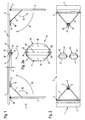
- Fig. 1 shows a designed as a beer table 1 leisure furniture, which has a support plate 2 serving as a table top.
- This support plate 2 consists of a first plate half 3 and a second plate half 4. In the in Fig. 1 shown position, the two plate halves 3 and 4 are in a common plane, so that the support plate 2 is also flat.
- stand elements 5 and 6 are provided in the end regions of the support plate. These stand elements 5 and 6 are in a standing position and accordingly extend substantially perpendicular to the support plate 2. This standing position of the stand elements 5, 6 is respectively fixed by means of a support bracket 7 and 8 respectively.
- Each of the support bracket 7 and 8 is assigned to the underside of the support plate 2, a latching device 9 and 10, in which the support bracket with a transverse locking portion 11 and 12 ( Fig. 2 and 4 ) are engaged.
- the locking devices 9 and 10 each have a release lever 13 or 14, by the actuation of the support bracket 7 and 8 are released with their locking portions 11 and 12, so that the support bracket 7 and 8 are removable from the respective associated locking device 9 and 10 respectively.
- the two plate halves 3 and 4 are connected to each other via two pivoting devices 15.
- the two identically formed pivoting devices 15 are each formed of a first and a second pivoting bracket 16 and 17.
- This swivel bracket 16 and 17 are made of a sheet metal component and each form a mounting plate 18 and 19, respectively, via which the swivel bracket 16 and 17 are each mounted fixedly on the underside of the respectively associated plate half 3 and 4 respectively.
- screw or the like Be provided for assembly.
- the swivel bracket 16 and 17 are formed as sheet metal components and bent several times.
- these swivel bracket 16 and 17 each form two spaced-apart bearing plates 20, 21 and 22 and 23.
- These bearing plates 20 and 21 and 22 and 23 are perpendicular or perpendicular to the two plate halves 3 and 4 aligned and parallel to each other.
- the bearing plates 20 and 21 or 22 and 23 at a corresponding distance from each other.
- These bearing plates 20 to 23 define a pivot axis 24, which has a predetermined distance a from the underside of the two plate halves 3, 4 or the support plate 2.
- the bearing plates 21 and 23 and the bearing plates 20 and 22 are in each case via a bearing pin 25 and 26 pivotally connected to each other.
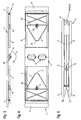
- the two stand elements 5 and 6 In order to bring the beer table 1 in its transport and / or storage position, now the two stand elements 5 and 6 must first be folded in the direction of the arrows 30 and 31 respectively. For this purpose, first the two support brackets 7 and 8 are disengaged from the associated locking devices 9 and 10 and brought by appropriate pivoting in the direction of the arrows 32 and 33 down into an integrated position in the respective stand element 5 and 6 respectively. After the support bracket 7 and 8 are "folded", now the stand elements 5 and 6 in the in Fig. 3 shown transported or storage position.
- the frame-like standing elements 5 and 6 have a transverse locking bar 34 and 35, with which the stand elements 5 and 6 in their transport or storage position fixed to the locking devices 9 and 10 are engageable. This is well known in the art.
- Fig. 4 It can be seen that the two support brackets 7 and 8 attached to the respectively associated locking rod 34 and 35 are. The locking rods 34 and 35 are rotatably received in the state elements 5 and 6 respectively.
- the stand elements 5 and 6 in the in 3 and 4 shown positions now the two plate halves 3 and 4 of the support plate 2 can be folded in the direction of the arrow 27.
- the resulting transport or storage position is in Fig. 5 shown.
- the two plate halves 3 and 4 are substantially parallel to each other and are connected to one another via the pivoting devices 15 or their bearing plates 20 to 23 at a predetermined distance.
- the stand elements 5 and 6 in the present embodiment in this transport or storage position due to the fixation of the state elements 5 and 6 in the locking devices 9 and 10 parallel to each other running each other.
- this parallel course of the plate halves 3 and 4 can also be achieved by the two spacer elements 36 and 37, as shown in FIG Fig. 5 is indicated.
- the two plate halves 3 and 4 can be brought to an extremely small pack size by the pivoting devices 15 according to the invention.
- the pivoting means 15 also allow a very stable support of the two plate halves 3 and 4 in their extended position forming the support plate 2.
- pivoting devices 15 may be sufficient for the normal use of the beer table 1 and in particular the support plate 2 give sufficient stability even at higher loads.
- beer table according to the preceding figures but also be used at increased vertical loads, it may be necessary to provide additional fixing.
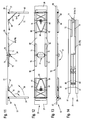
- Such additional fixation devices are exemplary Fig. 6 to 10 removable.
- These two locking plates 40 and 41 rest on the underside on the one hand on the first plate half 3 and on the other hand on the second plate half 4.
- the locking plate 40 is rotatably mounted on the second plate half 4 via a bearing pin 42.
- the locking plate 40 is stationary with the first plate half 3 via a locking pin 43 in connection.
- the latch plate 40 with the locking pin 43 can be disengaged.
- the locking plate 40 has a corresponding receiving slot 45 in the region of this locking pin 43.
- the storage and fixation of the latch plate 41 is made. So this is rotatably mounted in the present embodiment, the first plate half 3 via a bearing pin 46. With her the journal 46 opposite end portion of the latch plate 41 is in turn also with a locking pin 47 into engagement. This engagement can be canceled by turning or pivoting the latch plate 41 in the direction of arrow 48. Accordingly, the locking plate 41 in the region of the locking pin 47 has a receiving slot 49 which is open on one side.
- the two locking plates 40 and 41 consist of a metallic angle profile, whereby an increased bending stiffness is achieved.
- Fig. 7 is further seen that the latch plates 40 and 41 in their in the 6 and 7 shown latching position just below the two plate halves 3 and 4 abut.
- an additional stiffening of the two plate halves 3 and 4 is achieved in particular in the connecting region.
- an increased load capacity is ensured even at higher vertical loads, in particular in this connection region between the two plate halves 3 and 4.
- the two plate halves 3 and 4 can now be folded in the direction of the arrow 27, so that they are in their in Fig. 10 reach shown transport or storage position. Also from this Fig. 10 It can be seen that the two plate halves 3 and 4 in this transport or storage position are substantially parallel to each other and the two stand elements 5 and 6 "lie on each other". On the right side here is also the distance between the two plate halves. 3 and 4 by the pivoting devices 15 and the bearing plates 20 to 23 set.
- seat 55 has a serving as a seat plate support plate 56.
- This support plate 56 is formed from a first plate half 57 and a second plate half 58, which lie in the illustrated standing position in a common plane.
- stand members 59 and 60 are provided in the two outer end portions of the support plate 56 .
- the two stand elements 59 and 60 are located in Fig. 11 each in a perpendicular to the support plate 56 extending position, which is fixed in each case, for example, by corresponding support bracket 61 and 62.
- This support bracket 61 and 62 are in turn in turn each with a locking device 63 and 64 in connection.
- the support bracket 61 and 62 as already described to the support brackets 7 and 8, transverse latching portions 65 and 66, as is apparent from Fig. 12 are recognizable.
- the locking devices 63 and 64 are each also provided with a release lever 67 and 68, respectively. By appropriate actuation of these release levers 67 and 68 thus the latching connection between the locking elements 63 and 64 and the latching portions 65 and 66 can be canceled.
- the two plate halves 57 and 58 are pivotally connected to one another via a pivoting device 15.
- This pivoting device 15 is identical in the present embodiment designed as the two pivoting devices 15 of the beer table 1 from Fig. 1 , In that regard, reference is made to the description there.
- the pivoting device with its spaced from the plate halves 57, 58 pivot axis 24 causes the plate halves 57 and 58 in the illustrated standing position with their end faces 75 and 56 mutually supported each other stationary.
- two sliding bars 69 and 70 are provided on the underside, in the region of the longitudinal edges of the plate halves 57 and 58.
- These two sliding latch 69 and 70 are shown in the drawing figures 11 to 13 in their "blocking position".
- the two slide bars 69 and 70 in the Fig. 11 to 13 shown in dashed lines. In their blocking position, the two sliding bars 69 and 70 are inserted into the associated tubular elements 71 and 72, so that the standing position of the seat 55 from Fig. 11 fixed fixed.
- the two sliding latch 69 and 70 are retractable to a neutral position, as shown in the Fig. 11 to 13 is shown in phantom lines.
- this retracted neutral position thus the fixing effect of the sliding bolt 69 and 70 is repealed, since they are no longer in engagement with the respective pipe member 72.
- the two uprights 59 and 60 can be brought by pivoting in the direction of arrows 30 and 31 in their transport or storage position, as shown in Fig. 12 is shown.
- the two uprights 59 and 60 are formed like a frame and each have a locking bar 73 and 74, via which the stand elements 59 and 60 are latchingly engageable with the respective associated locking devices 63 and 64 in engagement. This also their transport or storage position is fixed fixed.
- the two plate halves 57 and 58 can now be pivoted in the direction of arrow 27 against each other, so that they from the in Fig. 13 shown position in the off Fig. 14 apparent transport or storage position can be brought. It is off Fig. 14
- the two stand elements 59 and 60 lie on one another and the two plate halves 57 and 58 on the right side via the pivoting device 15 and the bearing plates 20 to 23 at a predetermined distance with each other. Due to the configuration of the pivoting device 15, this predetermined distance is chosen such that in the illustrated transport or storage position, the two plate halves 57 and 58 are substantially parallel to each other.
- two spacer elements 36 and 37 are also provided on the underside in the area of the stand elements 59, 60, which, as this particular Fig. 14 can be seen to serve for the parallel alignment of the two support plates 56 and 57 in the folded state. Accordingly, this is also the description of the Fig. 1 and 5 on the FIGS. 11 and 14 to read.
- the sliding bars 69 and 70 are no longer in engagement with the respectively assigned tube element 72, but are held securely on the second plate half 58 in the tube element 71.
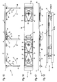
- an additional stand element 80 may be provided, as for the seat 55 from the 15 to 18 is apparent.
- the basic configuration of the seat 55 is substantially identical to the seat 55 of the Fig. 11 to 14 so that accordingly in the 15 to 18 also the same reference numerals for the same components are registered. In that regard, the above description to the Fig. 11 to 14 on the 15 to 18 to read.
- the third stand element 80 with respect to its attachment and its basic structure may be formed identical to the two stand elements 59 and 60 of the seat 55 from the Fig. 11 to 14 , Out Fig. 15
- the third standing element 80 is also located in a position perpendicular to the two plate halves 57 and 58.
- the third standing element 80 is mounted on the underside of the first plate half 57 in the immediate vicinity of the pivoting device 15 fixed and pivotable.
- a support bracket 81 is also provided here, which also has a latching portion 83 for engaging in an additional latching device 82, as is made Fig. 16 is apparent.
- the latching device 82 is arranged in the present embodiment in the immediate vicinity of the pivoting device 15 on the underside of the second plate half 58. To release the latching connection between the support bracket 81 and its latching portion 83 and the latching device 82 also has this latching device 82 on a trigger 84. After triggering this locking connection can now be the third state element 80 in the direction of arrow 85 in the off Fig. 16 shown transport or storage position are brought.
- a fourth latching device 87 is provided in this case, which is arranged on the underside of the first plate half 57.
- This locking device 87 serves to fix the transport or storage position of the third state element 80, as shown in particular from Fig. 16 is recognizable.
- FIGS. 16 and 17 are also the two other stand elements 59 and 60 shown in their transport or storage position and are fixed accordingly fixed to the two locking devices 63 and 64.
- the two uprights 59 and 60 are substantially level with each other. Due to the design and configuration of the pivoting device 15 and the bearing plates 20 to 23, in turn, the distance of the right end portions of the two plate halves 57 and 58 is determined such that the two plate halves 57 and 58 in the in Fig. 18 illustrated transport or storage position substantially parallel to each other. Furthermore, it can also be seen that the third stand element 80 is securely received in its transport or storage position between the two plate halves 57 and 58. The same applies to the locking device 82.
- the third standing element 80 can also be designed to be adjustable in length, so that the seat 55 can be set up safely on uneven ground.
- the support plate in two plate halves and the provided pivoting device (s) is the inventive furniture in its size in a simple manner on a manageable "Packlot" brought and can be transported in particular in a car. Due to the special design of the pivoting device 15, an extremely stable support plate is achieved in the constructed (unfolded) state.
- the swivel bracket 16 and 17 of the pivoting device 15 act on the basis of the distance of the pivot axis 24 from the underside of the plate halves as a kind of support lever, so that the support plate in the connecting region of the plate half can not bend or buckle.
- the plate halves are supported on the front side against each other and are determined by the pivot bracket 16 and 17 in this lying in a common plane position and held securely.
- the stability or achievable rigidity is sufficient at least for the normal loads of a table top.
- additional additional fixing devices may be provided, as described above, for example, to the drawing figures 6 to 10, 11 to 14 and 15 to 18 ,
Landscapes
- Life Sciences & Earth Sciences (AREA)
- Engineering & Computer Science (AREA)
- Wood Science & Technology (AREA)
- Tables And Desks Characterized By Structural Shape (AREA)
- Handcart (AREA)
Abstract
Description
Die Erfindung betrifft einen Biertisch oder eine Sitzbank mit einer als Tischplatte bzw. Sitzbankplatte dienenden ebenen Tragplatte, welche unterseitig mit wenigstens zwei klappbaren in den Endbereichen der Tragplatte angeordneten Standelementen versehen ist, welche aus einer im Wesentlichen senkrecht zur Tragplatte verlaufenden Standposition in eine etwa parallel zur Tragplatte verlaufende Transport- und/oder Lagerposition schwenkbar und wenigstens in ihrer jeweiligen Standposition fixierbar sind.The invention relates to a beer table or a bench seat with a serving as a table top or seat plate flat support plate which is provided on the underside with at least two hinged in the end regions of the support plate arranged stand elements, which consists of a substantially perpendicular to the support plate standing position in an approximately parallel to Support plate extending transport and / or storage position are pivotable and at least in their respective standing position can be fixed.
Freizeitmöbel der gattungsgemäßen Art, insbesondere in Form von Biertischen oder Bierbänken bzw. Sitzbänken sind schon seit langem bekannt. Solche Freizeitmöbel sind durch eine ebene Tragplatte gekennzeichnet, welche je nach Gesamtgestaltung des Freizeitmöbels als Sitzgelegenheit (Sitzbankplatte) oder als Tischplatte dient.Leisure furniture of the generic type, especially in the form of beer tables or beer benches or benches have long been known. Such leisure furniture is characterized by a flat support plate, which serves as a seat opportunity (bench seat) or as a table top depending on the overall design of the leisure furniture.
Insbesondere Bierbänke und nach dieser Art aufgebaute Sitzbänke weisen unterseitig in den jeweiligen Endbereichen der Tragplatte Standelemente auf, welche gewöhnlich rahmenartig aus verschiedenen Metallprofilen zusammengesetzt sind. Diese Standelemente sind in den Endbereichen der Tragplatte schwenkbar gelagert und können aus einer parallel zur Tragplatte verlaufenden Transport- und/oder Lagerposition in eine im Wesentlichen senkrecht zur Tragplatte verlaufende Standposition gebracht werden. Dabei sind die Standelemente zumindest in der Standposition feststehend fixierbar. Hierzu ist an jedem Standelement eine Art Stützbügel vorgesehen, welcher relativ zum Standelement schwenkbar ist. In der Standposition können diese Stützbügel einer jeweils zugeordneten, an der Unterseite der Tragplatte angeordneten Arretiereinrichtung befestigt werden. Solche Arretiereinrichtungen sind ebenfalls in unterschiedlichen Ausgestaltungen bekannt, wobei hier in der Regel lösbare Rasteinrichtungen eingesetzt werden. Diese Rasteinrichtungen sind an der Unterseite der Tragplatte in einem Abstand von der Schwenklagerung des jeweiligen Standelementes angeordnet, dass bei eingerastetem Stützbügel das jeweilige Standelement rechtwinklig bzw. senkrecht zur Tragplatte verlaufend ausgerichtet ist. Wird der Stützbügel an der Rasteinrichtung ausgerastet und in eine parallele Lage zum zugehörigen Standelement gebracht, kann dieses Standelement "eingeklappt" werden und in eine an der Tragplatte unterseitig anliegende bzw. zur Tragplatte parallele Transport- und/oder Lagerposition gebracht werden. Dabei weist das Standelement eine quer verlaufende Raststange auf, mit welcher das Standelement mit der jeweiligen Rasteinrichtung feststehend in Eingriff gebracht werden kann, so dass dessen Transport- und/oder Lagerposition lösbar gesichert ist.In particular, beer benches and benches constructed in this way have lower side in the respective end regions of the support plate to stand elements, which are usually frame-like composed of different metal profiles. These stand elements are pivotally mounted in the end regions of the support plate and can be brought from a parallel to the support plate extending transport and / or storage position in a substantially perpendicular to the support plate standing position. There are the stand elements fixed fixed at least in the standing position. For this purpose, a kind of support bracket is provided on each stand element, which is pivotable relative to the stand element. In the standing position, these support brackets of a respectively associated, arranged on the underside of the support plate locking device can be attached. Such locking devices are also known in different configurations, in which case releasable locking devices are used as a rule. These locking devices are arranged on the underside of the support plate at a distance from the pivot bearing of the respective stand element that, when the support bracket is latched, the respective upright element is aligned perpendicularly or perpendicular to the support plate. If the support bracket is disengaged from the latching device and placed in a parallel position to the associated stand element, this stand element can be "folded" and placed in a on the support plate on the underside fitting or parallel to the support plate transport and / or storage position. In this case, the stand element has a transverse locking bar, with which the stand element with the respective latching means can be fixedly brought into engagement, so that its transport and / or storage position is releasably secured.
Diese klappbaren Standelemente haben den Vorteil, dass ein solches Freizeitmöbel in Form eines Biertisches oder einer Sitzbank beim Transport weniger Raum einnimmt, insbesondere dessen Transporthöhe äußerst gering ist. Außerdem sind solche Garnituren auf Grund ihrer robusten Konstruktion äußerst stabil, so dass dies auch höhere Belastungen ohne weiteres aufnehmen können.These foldable stand elements have the advantage that such a piece of furniture in the form of a beer table or a seat occupies less space during transport, especially the transport height is extremely low. In addition, such trimmings are extremely stable due to their robust construction, so that they can accommodate even higher loads easily.
Bezüglich unterschiedlicher Ausgestaltungen solcher Biertische oder Sitzbänke sei beispielhaft auf die Druckschriften
Es hat sich nun gezeigt, dass durch die klappbaren Standelemente zwar eine geringe Transporthöhe erreichbar ist, jedoch die Länge der Tragplatte unverändert bleibt. Dies spielt für Großveranstaltungen in der Regel keinerlei Rolle, da für solche Veranstaltungen die auch als "Garnituren" bezeichneten Biertische und Sitzbänke per Lastkraftwagen oder Anhänger in großer Zahl zum Veranstaltungsort gebracht werden.It has now been shown that although a small transport height can be achieved by the hinged uprights, but the length of the support plate remains unchanged. This usually does not matter for major events, as the beer tables and benches, also referred to as "trimmings", are brought to the venue by truck or trailer in large numbers for such events.
Insbesondere im Privatbereich ist der Transport solcher Garnituren jedoch nicht immer einfach. Insbesondere hat nicht jede Privatperson ein Fahrzeug oder einen Anhänger zur Verfügung um eine Garnitur verstauen und transportieren zu können, da es häufig am notwenigen "Ladevolumen" mangelt. D.h., dass Personen, die eine "Garnitur" erwerben oder ausleihen wollen, häufig darauf angewiesen sind, sich ein Fahrzeug zu mieten oder sich die "Garnituren" anliefern zu lassen, was stets mit einem erhöhten Aufwand bzw. auch erhöhten Kosten verbunden ist.However, especially in the private sector, the transport of such trimmings is not always easy. In particular, not every individual has a vehicle or a trailer available to stow and transport a set of clothing, as it often lacks the necessary "load volume". That is, people who want to buy or rent a "set" are often relied on to rent a vehicle or to have the "sets" to be delivered, which is always associated with an increased cost or increased costs.
Demgemäß liegt der Erfindung die Aufgabe zugrunde, Freizeitmöbel in Form von sog. Biertischen und/oder Sitzbänken derart auszugestalten, dass diese auf ein möglichst kleines Transportmaß bringbar sind, wobei gleichzeitig eine immer noch genügend große Stabilität beim Einsatz solcher Freizeitmöbel gewährleistet bleiben soll.Accordingly, the invention has for its object to design recreational furniture in the form of so-called. Beer tables and / or benches so that they can be brought to the smallest possible Transportmaß, while still ensuring a sufficiently large stability in the use of such leisure furniture.
Die Aufgabe wird erfindungsgemäß dadurch gelöst, dass die Tragplatte zweiteilig ausgebildet ist und zwei Plattenhälften bildet und, dass die Plattenhälften über wenigstens eine Schwenkeinrichtung schwenkbar miteinander verbunden sind und, dass die Schwenkeinrichtung eine quer zu den Plattenhälften verlaufende Schwenkachse definiert, welche im Abstand zu den Plattenhälften angeordnet ist und, dass die Schwenkachse unterhalb der Plattenhälften in einem Abstand zu den Plattenhälften angeordnet ist, der so bemessen ist, dass die Plattenhälften im zusammengeklappten Zustand bei aufeinander "liegenden" Standelementen etwa parallel zueinander verlaufen und dass sich die Plattenhälften im aufgeklappten Zustand mit ihren einander zugewandten Stirnseiten zur Bildung der Tragplatte aneinander feststehend abstützen.The object is achieved in that the support plate is formed in two parts and forms two plate halves and that the plate halves are pivotally connected to each other via at least one pivoting device and that the pivoting device extending transversely to the plate halves Defined pivot axis, which is arranged at a distance from the plate halves and that the pivot axis is arranged below the plate halves at a distance from the plate halves, which is dimensioned so that the plate halves in the folded state with mutually "standing" stand elements approximately parallel to each other and that support the plate halves in the unfolded state with their facing end faces to form the support plate to each other fixed.
Durch die erfindungsgemäße Ausgestaltung wird ein Freizeitmöbel, insbesondere ein Biertisch und/oder eine Sitzbank zur Verfügung gestellt, welche zumindest soweit verkleinerbar ist, dass sie in einem herkömmlichen PKW mittlerer Größe Platz findet.The inventive design a leisure furniture, in particular a beer table and / or a bench is provided, which is at least as small as possible that it fits into a conventional car medium size.
Dazu ist vorgesehen, dass die Tragplatte zweiteilig ausgebildet ist und zwei Plattenhälften bildet. Um diese Plattenhälften gegeneinander verschwenken zu können, ist eine Schwenkeinrichtung vorgesehen, über welche die Plattenhälften miteinander verbunden sind. Um die Plattenhälften in eine parallel zueinander verlaufende Transportstellung bringen zu können, bildet die Schwenkeinrichtung eine quer zu den Plattenhälften verlaufende Schwenkachse, welche im Abstand zu den Plattenhälften angeordnet ist. Des Weiteren ist diese Schwenkachse unterhalb der Plattenhälften angeordnet, so dass die Plattenhälften in zusammengeklapptem Zustand mit den eingeklappten Standelementen aufeinander liegen. Damit wird ebenfalls durch dieses Zusammenklappen eine noch relativ geringe Transporthöhe erreicht, wobei sich die Gesamtlänge des Freizeitmöbels etwa halbiert.For this purpose, it is provided that the support plate is formed in two parts and forms two plate halves. In order to pivot these plate halves against each other, a pivot means is provided, via which the plate halves are interconnected. In order to bring the plate halves in a mutually parallel transport position, the pivoting means forms a transverse to the plate halves pivot axis, which is arranged at a distance from the plate halves. Furthermore, this pivot axis is arranged below the plate halves, so that the plate halves lie in the folded state with the folded-in stand elements on each other. Thus, a relatively low transport height is also achieved by this folding, with the total length of the leisure furniture is about halved.
Des Weiteren soll der Abstand der Schwenkachse unterhalb der Plattenhälften derart gewählt sein, dass die Plattenhälften im zusammengeklappten Zustand bei aufeinander liegenden Standelementen etwa parallel zueinander verlaufen. Der Abstand der Schwenkachse von den Plattenhälften ist dabei so gewählt, dass sich die Plattenhälften in aufgeklapptem Zustand mit ihren einander zugewandten Stirnseiten zur Bildung der Tragplatte aneinander feststehend abstützen. Aufgrund des definierten Abstandes der Schwenkachse zu den Plattenhälften wird insbesondere in aufgeklapptem Zustand eine äußerst hohe Stabilität der durch die beiden Plattenhälften gebildeten Tragplatte erreicht. D. h., dass die Schwenkeinrichtung eine genügend große Hebelwirkung im aufgeklappten Zustand auf die beiden Plattenhälften ausübt, so dass im Verbindungsbereich ein Durchknicken oder Durchbrechen der Plattenhälften sicher verhindert ist. Diese Ausgestaltung ist insbesondere für Freizeitmöbel geeignet, die als Biertisch ausgebildet sind und somit lediglich eine etwas geringere Tragkraft aufweisen müssen.Furthermore, the distance between the pivot axis should be chosen below the plate halves such that the plate halves in the folded state with mutually parallel stand elements approximately parallel to each other. The distance between the pivot axis of the plate halves is chosen so that the plate halves in the unfolded state with their each other facing end faces to form the support plate to support each other. Due to the defined distance of the pivot axis to the plate halves, an extremely high stability of the support plate formed by the two plate halves is achieved in particular in the unfolded state. D. h. That the pivoting device exerts a sufficiently large leverage effect in the unfolded state on the two plate halves, so that in the connection area a kinking or breaking of the plate halves is reliably prevented. This embodiment is particularly suitable for leisure furniture, which are designed as a beer table and thus only need to have a slightly lower load capacity.
Weitere vorteilhafte Ausgestaltungen der Erfindung sind den weiteren Unteransprüchen entnehmbar.Further advantageous embodiments of the invention can be taken from the further subclaims.
So kann gemäß Anspruch 2 vorgesehen sein, dass die Standelemente im zusammengeklappten Zustand der Plattenhälften aufeinander liegen oder, dass im Bereich der Standelemente Distanzelemente vorgesehen sind, durch welche die Plattenhälften im zusammengeklappten Zustand in einem Abstand voneinander gehalten sind, welcher doppelt so groß ist wie der Abstand (a) der Schwenkachse zu den Plattenhälften. Hierdurch wird sichergestellt, dass die Plattenhälften im zusammengeklappten Zustand parallel zueinander verlaufen wodurch insbesondere die Handhabung beim Transport erleichtert wird und das Packmaß auf ein Minimum reduziert ist.Thus, it can be provided according to
Weiter kann gemäß Anspruch 3 vorgesehen sein, dass die Schwenkeinrichtung wenigstens einen ersten und einen zweiten Schwenkbügel umfasst, die im Trennbereich der Plattenhälften jeweils an einer der Plattenhälften unterseitig angeordnet sind. Dabei bildet jeder der Schwenkbügel zwei voneinander beabstandete Lagerlaschen, die parallel zueinander verlaufen und rechtwinklig zu den Plattenhälften angeordnet sind. Diese Lagerlaschen des ersten Schwenkbügels sind mit den Lagerlaschen des zweiten Schwenkbügels wechselseitig schwenkbar verbunden. Durch diese einfache Ausgestaltung der Schwenkeinrichtung gemäß Anspruch 2 wird einerseits eine äußerst stabile Schwenkeinrichtung zur Verfügung gestellt, welche andererseits auch äußerst einfach herstellbar ist.Further, it can be provided according to
D. h., dass diese Schwenkbügel letztendlich aus Blechbauteilen ausgestanzt und gebogen werden können, wie dies gemäß Anspruch 4 beansprucht ist.D. h., That these swivel bars can ultimately be punched out of sheet metal components and bent, as claimed in
Dabei können, insbesondere an einem Biertisch auch zwei solcher aus den Schwenkbügeln bestehende Schwenkeinrichtungen eingesetzt werden, wodurch eine höhere Stabilität erreicht wird. Die Ausgestaltung der Schwenkeinrichtung ist allerdings nicht auf die Ausbildung als Schwenkbügel beschränkt. Es sind hier auch andere stabile Konstruktionen mit gleicher Funktionalität, wie beispielsweise ineinander greifende Lagerböcke oder dgl. denkbar.In this case, in particular on a beer table, two such pivoting devices consisting of the swivel clamps can be used, whereby a higher stability is achieved. However, the design of the pivoting device is not limited to the training as a swivel bracket. There are also other stable structures with the same functionality, such as interlocking bearing blocks or the like. Conceivable.
Des Weiteren kann gemäß Anspruch 5 eine zusätzliche Fixierung des aufgeklappten Zustandes der die Tragplatten bildenden Plattenhälften vorgesehen sein. Hierzu ist unterseitig wenigstens eine Fixiereinrichtung vorgesehen, welche mit beiden Plattenhälften gleichzeitig form- und/oder kraftschlüssig in Eingriff bringbar ist. Eine solche zusätzliche Fixierung der beiden Plattenhälften kann insbesondere bei der Ausbildung des Freizeitmöbels als Sitzbank von Vorteil sein, um eine höhere Stabilität der Tragplatte auch bei höheren Belastungen zu erreichen.Furthermore, according to
Dazu können unterschiedlich ausgestaltete zusätzliche Fixiereinrichtungen vorgesehen sein.For this purpose, differently configured additional fixing devices can be provided.
So kann eine solche zusätzliche Fixiereinrichtung gemäß Anspruch 5 aus einer profilierten Riegelplatte bestehen, welche unterseitig anliegend an der einen Plattenhälfte schwenkbar gelagert ist. Diese Riegelplatte ist im aufgeklappten Zustand der beiden Plattenhälften mit einem Halteelement der anderen Plattenhälfte an dieser unterseitig anliegend feststehend in Eingriff bringbar. Diese Ausgestaltung gemäß Anspruch 6 stellt eine äußerst einfache und dennoch stabile zusätzliche Fixiereinrichtung für ein erfindungsgemäßes Freizeitmöbel dar.Thus, such an additional fixing device according to
Um größere vertikale Belastungen aufnehmen zu können, kann die zusätzliche Fixiereinrichtung gemäß Anspruch 7 auch aus einem unterseitig an der einen Plattehälfte längs verschiebbaren Schieberiegel bestehen. Dieser Schieberiegel ist des Weiteren in aufgeklapptem Zustand der beiden Plattenhälften mit einem an der anderen Plattenhälfte unterseitig angeordneten Riegelelement in Eingriff bringbar.In order to accommodate greater vertical loads, the additional fixing device according to claim 7 may also consist of a lower side of the plate half longitudinally slidable sliding latch. This slide bar is further engageable in the unfolded state of the two plate halves with a lower plate arranged on the other half of the plate locking element.
Dabei kann gemäß Anspruch 8 vorgesehen sein, dass der Schieberiegel rohrförmig, insbesondere als Vierkantrohr ausgebildet ist und in einem formangepassten, an der Unterseite der einen Plattenhälfte angeordneten Rohrelement längs verschiebbar aufgenommen ist. Dabei ist der Schieberiegel aus einer neutralen, zurückgezogenen Ausgangsstellung in eine die beiden Plattenhälften starr miteinander verbindende Riegelstellung bringbar. In dieser Riegelstellung greift der Schieberiegel in ein ebenfalls rohrförmig ausgebildetes Aufnahmeelement in Form eines zweiten Rohrelementes formschlüssig ein. Zwischen dem Schieberiegel und den Rohrelementen ist vorzugsweise ein geringes Spiel vorgesehen. Aufgrund der rohrförmigen Ausbildung des Schieberiegels sowie auch der Rohrelemente wird - auch in Verbindung mit dem geringen Spiel eine äußerst hohe Stabilität der aus den Plattenhälften gebildeten Tragplatte erreicht.It can be provided according to
Des Weiteren kann aber gemäß Anspruch 9 zusätzlich oder anstatt der vorangegangen beschriebenen Fixiereinrichtung auch ein drittes Standelement vorgesehen sein. Dieses Standelement ist unterseitig an einer der Plattenhälften aus einer etwa parallel zur Plattenhälfte verlaufenden Transport- und/oder Lagerposition in eine im Wesentlichen senkrecht zur Plattenhälfte verlaufende Standposition schwenkbar. D. h., dass zunächst durch dieses zusätzliche dritte Standelement die eine Plattenhälfte etwa im Verbindungsbereich zur anderen Plattenhälfte zusätzlich am Untergrund abgestützt ist. Dabei kann dieses zusätzliche Standelement auch höhenverstellbar ausgebildet sein, um diverse Unebenheiten des Untergrundes auszugleichen. Die andere Plattenhälfte wird über die Schwenkeinrichtung stabil an der ersten Plattenhälfte über die Schwenkeinrichtung gehalten. Auch kann an dem zusätzlichen, dritten Standelement ein Stützsteg vorgesehen sein, auf welchem die andre Plattenhälfte abgestützt wird.Furthermore, however, according to
Um jedoch auch die andere Plattenhälfte zusätzlich vertikal abzustützen und damit eine Überlastung der Schwenkeinrichtung sicher auszuschließen, kann gemäß Anspruch 10 vorgesehen sein, dass das dritte Standelement mittels eines ersten Rastelementes in seiner Transport- und/oder Lagerposition an der einen Plattenhälfte fixierbar ist und dass an der anderen Plattenhälfte ein zweites Rastelement vorgesehen ist und dass das dritte Standelement einen schwenkbaren Stützbügel aufweist, welcher in der Standposition des Standelementes feststehend mit dem dritten Rastelement lösbar in Eingriff steht. Durch diesen Stützbügel, welcher einerseits die Standposition des dritten Standelementes fixiert, wird gleichzeitig auch eine vertikale Abstützung der anderen Plattenhälfte erreicht, so dass durch diese Ausgestaltung eine äußerst stabile und tragfähige Sitzbank erreicht wird.However, to additionally support the other plate half vertically and thus exclude overloading of the pivoting device can be provided according to
Anhand der Zeichnung wird nachfolgend die Erfindung näher erläutert. Die nachfolgenden Zeichnungen zeigen dabei lediglich beispielhaft unterschiedliche Freizeitmöbel, insbesondere Ausführungsvarianten von Biertischen sowie Ausführungsvarianten von Sitzbänken. Es zeigt:
- Fig. 1
- eine Seitenansicht eines erfindungsgemäßen Biertisches mit aufgeklappten Standelementen;
- Fig. 2
- eine Unteransicht des Biertisches aus
Fig. 1 ; - Fig. 2a
- eine vergrößerte Draufsicht einer Schwenkeinrichtung aus
Fig. 2 ; - Fig. 3
- eine Seitenansicht des Biertisches aus
Fig. 1 mit eingeklappten Standelementen; - Fig. 4
- eine Unteransicht des Biertisches aus
Fig. 3 ; - Fig. 5
- den Biertisch aus den vorangegangenen Zeichnungsfiguren in vollständig zusammengeklapptem Zustand;
- Fig. 6
- eine Unteransicht des Biertisches aus
Fig. 1 mit aufgeklappten Standelementen sowie zusätzlich unterseitig angeordneten zur Versteifung dienenden Riegelplatten; - Fig. 7
- den Biertisch aus
Fig. 6 in Seitenansicht; - Fig. 8
- eine Unteransicht des Biertisches aus den
Fig. 6 und 7 mit eingeklappten Standelementen sowie sich in einer neutralen Position befindlichen Riegelplatten; - Fig. 9
- eine Seitenansicht des Biertisches aus
Fig. 8 ; - Fig. 10
- den Biertisch aus den
Fig. 6 in vollständig zusammengeklapptem Zustand;bis 9 - Fig. 11
- eine Seitenansicht eines als Sitzbank ausgebildeten Freizeitmöbels mit ausgeklappten Standelementen sowie zusätzlich an der Unterseite angeordneten Fixiereinrichtungen, welche Schieberiegel aufweisen;
- Fig. 12
- eine Unteransicht der Sitzbank aus
Fig. 11 mit eingeklappten Standelementen sowie noch verriegelten Schieberiegeln; - Fig. 13
- eine Seitenansicht der Sitzbank aus
Fig. 12 ; - Fig. 14
- eine Seitenansicht der Sitzbank aus den
Fig. 11 in vollständig zusammengeklapptem Zustand;bis 13 - Fig. 15
- eine Seitenansicht einer Sitzbank mit aufgeklappten Standelementen, welche als zusätzliche Fixiereinrichtung ein zusätzliches drittes Standelement aufweist;
- Fig. 16
- eine Unteransicht der Sitzbank aus
Fig. 15 mit eingeklappten Standelementen; - Fig. 17
- eine Seitenansicht der Sitzbank aus
Fig. 16 ; - Fig. 18
- die Sitzbank aus den
Fig. 15 in vollständig zusammengeklapptem Zustand.bis 17
- Fig. 1
- a side view of a beer table according to the invention with unfolded stand elements;
- Fig. 2
- a bottom view of the beer table
Fig. 1 ; - Fig. 2a
- an enlarged plan view of a pivoting device
Fig. 2 ; - Fig. 3
- a side view of the beer table
Fig. 1 with folded up stand elements; - Fig. 4
- a bottom view of the beer table
Fig. 3 ; - Fig. 5
- the beer table from the preceding figures in the fully folded state;
- Fig. 6
- a bottom view of the beer table
Fig. 1 with unfolded stand elements and additionally arranged on the underside serving for stiffening latch plates; - Fig. 7
- the beer table
Fig. 6 in side view; - Fig. 8
- a bottom view of the beer table from the
6 and 7 with folded up stand elements as well as in a neutral position located latch plates; - Fig. 9
- a side view of the beer table
Fig. 8 ; - Fig. 10
- the beer table from the
Fig. 6 to 9 in fully folded condition; - Fig. 11
- a side view of a trained as a seat leisure furniture with folded up stand elements and additionally arranged on the bottom fixing means having sliding latch;
- Fig. 12
- a bottom view of the seat
Fig. 11 with folding upright elements as well as still locked slide seals; - Fig. 13
- a side view of the seat
Fig. 12 ; - Fig. 14
- a side view of the bench from the
Fig. 11 to 13 in fully folded condition; - Fig. 15
- a side view of a bench with unfolded stand elements, which has an additional third state element as an additional fixing device;
- Fig. 16
- a bottom view of the seat
Fig. 15 with folded up stand elements; - Fig. 17
- a side view of the seat
Fig. 16 ; - Fig. 18
- the bench from the
15 to 17 in fully folded condition.
Unterseitig sind in den Endbereichen der Tragplatte 2 Standelemente 5 und 6 vorgesehen. Diese Standelemente 5 und 6 befinden sich in einer Standposition und verlaufen dementsprechend im Wesentlichen senkrecht zur Tragplatte 2. Diese Standposition der Standelemente 5, 6 wird jeweils mittels eines Stützbügels 7 bzw. 8 fixiert. Jedem der Stützbügel 7 bzw. 8 ist unterseitig an der Tragplatte 2 eine Rasteinrichtung 9 bzw. 10 zugeordnet, in welche die Stützbügel mit einem quer verlaufenden Rastabschnitt 11 bzw. 12 (
Des Weiteren ist aus den Zeichnungsfiguren 1 und 2 erkennbar, dass die beiden Plattenhälften 3 und 4 über zwei Schwenkeinrichtungen 15 miteinander in Verbindung stehen. Beim vorliegenden Ausführungsbeispiel werden die beiden identisch ausgebildeten Schwenkeinrichtungen 15 aus jeweils einem ersten und einem zweiten Schwenkbügel 16 und 17 gebildet. Diese Schwenkbügel 16 und 17 sind aus einem Blechbauteil hergestellt und bilden jeweils eine Montageplatte 18 bzw. 19, über welche die Schwenkbügel 16 und 17 jeweils unterseitig an der jeweils zugehörigen Plattenhälfte 3 bzw. 4 feststehend montiert sind. Zur Montage können hier beispielsweise Schraubverbindungen oder dgl. vorgesehen sein. Weiter ist aus
Wie insbesondere aus der vergrößerten Darstellung einer der beiden Schwenkeinrichtungen 15 der
Es ist leicht vorstellbar, dass aufgrund dieser Schwenklagerungen 15 die beiden Plattenhälften 3 und 4 in Richtung des Pfeiles 27 gegeneinander verschwenkt werden können. Aufgrund des Abstandes a der Schwenkachse 24 von der Tragplatte 2 stützen sich in der in
Um den Biertisch 1 in seine Transport- und/oder Lagerposition bringen zu können, müssen nun zunächst die beiden Standelemente 5 und 6 in Richtung der Pfeile 30 bzw. 31 eingeklappt werden. Dazu werden zunächst die beiden Stützbügel 7 und 8 aus den zugehörigen Rasteinrichtungen 9 und 10 ausgerastet und durch entsprechendes Verschwenken in Richtung der Pfeile 32 und 33 nach unten in eine im jeweiligen Standelement 5 bzw. 6 integrierte Position gebracht. Nachdem die Stützbügel 7 und 8 "eingeklappt" sind, werden nun die Standelemente 5 und 6 in die in
Dabei ist insbesondere aus
Nachdem nun die Standelemente 5 und 6 in die in
Es ist erkennbar, dass durch die erfindungsgemäße Schwenkeinrichtungen 15 die beiden Plattenhälften 3 und 4 auf ein äußerst geringes Packmaß bringbar sind. Andererseits erlauben die Schwenkeinrichtungen 15 auch eine äußerst stabile Abstützung der beiden Plattenhälften 3 und 4 in ihrer die Tragplatte 2 bildenden gestreckten Lage.It can be seen that the two
Das Vorsehen dieser beiden Schwenkeinrichtungen 15 kann für den normalen Einsatz des Biertisches 1 ausreichend sein und insbesondere der Tragplatte 2 eine ausreichende Stabilität auch bei höheren Belastungen geben.The provision of these two
Soll der Biertisch nach den vorangegangenen Figuren jedoch auch bei erhöhten Vertikalbelastungen eingesetzt werden, so kann es erforderlich sein, zusätzliche Fixiereinrichtungen vorzusehen.If the beer table according to the preceding figures but also be used at increased vertical loads, it may be necessary to provide additional fixing.
Solche zusätzlichen Fixiereinrichtungen sind beispielhaft den
Dabei sind in diesen Zeichnungsfiguren für die gleichen Bauteile die gleichen Bezugszeichen verwendet wie bereits zu den
Aus den
In gleicher Art und Weise ist auch die Lagerung und Fixierung der Riegelplatte 41 vorgenommen. So ist diese beim vorliegenden Ausführungsbeispiel an der ersten Plattenhälfte 3 über einen Lagerzapfen 46 drehbar gelagert. Mit ihrem dem Lagerzapfen 46 gegenüberliegenden Endbereich steht die Riegelplatte 41 wiederum ebenfalls mit einem Riegelzapfen 47 in Eingriff. Dieser Eingriff kann durch Drehen bzw. Schwenken der Riegelplatte 41 in Richtung des Pfeiles 48 aufgehoben werden. Dementsprechend weist auch die Riegelplatte 41 im Bereich des Riegelzapfens 47 einen einseitig offenen Aufnahmeschlitz 49 auf.In the same way, the storage and fixation of the
Des Weiteren ist insbesondere aus
Aus
Um nun den Biertisch 1 aus den
Anschließend können nun die beiden Plattenhälften 3 und 4 in Richtung des Pfeiles 27 zusammengeklappt werden, so dass sie in ihre in
Wie bereits eingangs erwähnt, können als zusätzliche Fixiereinrichtungen verschiedene Varianten vorgesehen sein, wie diese beispielhaft in den
Die in
Diese Stützbügel 61 und 62 stehen ihrerseits wiederum jeweils mit einer Rasteinrichtung 63 bzw. 64 in Verbindung. Dazu weisen die Stützbügel 61 und 62, wie bereits zu den Stützbügeln 7 und 8 beschrieben, quer verlaufende Rastabschnitte 65 und 66 auf, wie dies aus
Weiter ist aus den Zeichnungsfiguren 11 bis 14 erkennbar, dass die beiden Plattenhälften 57 und 58 über eine Schwenkeinrichtung 15 miteinander schwenkbar in Verbindung stehen. Diese Schwenkeinrichtung 15 ist beim vorliegenden Ausführungsbeispiel identisch ausgebildet wie die beiden Schwenkeinrichtungen 15 des Biertisches 1 aus
Seitlich neben der Schwenkeinrichtung 15 sind unterseitig, im Bereich der Längskanten der Plattenhälften 57 und 58 zwei Schieberiegel 69 und 70 vorgesehen. Diese beiden Schieberiegel 69 und 70 sind in den Zeichnungsfiguren 11 bis 13 in ihrer "Sperrstellung" dargestellt. Des Weiteren ist erkennbar, dass unterseitig an jeder der Plattenhälften 57 und 58 zur Aufnahme eines Schieberiegels 69 oder 70 entsprechende Rohrelemente 71 und 72 vorgesehen sind. Dementsprechend sind die beiden Schieberiegel 69 und 70 in den
Aus dieser Riegelposition sind die beiden Schieberiegel 69 und 70 in eine neutrale Position zurückziehbar, wie dies in den
Des Weiteren ist ebenfalls aus
Anschließend können nun die beiden Plattenhälften 57 und 58 in Richtung des Pfeiles 27 gegeneinander verschwenkt werden, so dass sie aus der in
Auch die aus den Schieberriegeln 69 und 70 sowie den Rohrelementen 71 und 72 bestehende zusätzliche Fixiereinrichtung ist derart stabil ausgestaltet, dass mehrere Personen auf der Sitzbank 55 sitzen können, ohne dass die Sitzbank 55 Schaden nehmen kann.Also consisting of the slide bars 69 and 70 and the
Sollte die Sitzbank mit äußerst hohen Belastungen beaufschlagt werden, so kann anstatt der Schieberiegel 69 und 70 unterseitig ein zusätzliches Standelement 80 vorgesehen sein, wie dies für die Sitzbank 55 aus den
Dabei kann das dritte Standelement 80 bezüglich seiner Befestigung sowie seines grundsätzlichen Aufbaus identisch ausgebildet sein wie die beiden Standelemente 59 und 60 der Sitzbank 55 aus den
Die Rasteinrichtung 82 ist beim vorliegenden Ausführungsbeispiel in unmittelbarer Nachbarschaft zur Schwenkeinrichtung 15 unterseitig an der zweiten Plattenhälfte 58 angeordnet. Zum Lösen der Rastverbindung zwischen dem Stützbügel 81 bzw. dessen Rastabschnitt 83 und der Rasteinrichtung 82 weist auch diese Rasteinrichtung 82 einen Auslösehebel 84 auf. Nach dem Auslösen dieser Rastverbindung kann nun das dritte Standelement 80 in Richtung des Pfeiles 85 in die aus
Da auch der Stützbügel 81 über eine Raststange 86 schwenkbar im dritten Standelement 80 aufgenommen wird, ist in diesem Falle eine vierte Rasteinrichtung 87 vorgesehen, welche unterseitig an der ersten Plattenhälfte 57 angeordnet ist. Diese Rasteinrichtung 87 dient zur Fixierung der Transport- oder Lagerposition des dritten Standelementes 80, wie dies insbesondere aus den
Nachdem diese Transport- oder Lagerposition der
Es ist erkennbar, dass in dieser Transport- oder Lagerposition der Sitzbank 55 die beiden Standelemente 59 und 60 im Wesentlichen planeben aufeinander liegen. Durch die Ausbildung und Ausgestaltung der Schwenkeinrichtung 15 bzw. deren Lagerlaschen 20 bis 23 wird wiederum auch der Abstand der rechten Endbereiche der beiden Plattenhälften 57 und 58 derart bestimmt, dass die beiden Plattenhälften 57 und 58 in der in
An dieser Stelle sei noch erwähnt, dass das dritte Standelement 80 auch längenverstellbar ausgebildet sein kann, so dass die Sitzbank 55 sicher auf unebenem Untergrund aufstellbar ist.At this point, it should be mentioned that the third standing
Zusammenfassend ist erkennbar, dass durch die Teilung der Tragplatte in zwei Plattenhälften und die vorgesehen Schwenkeinrichtung(en) ist das erfindungsgemäße Freizeitmöbel in seiner Größe in einfacher Weise auf ein handhabbares "Packmaß" bringbar und kann insbesondere in einem PKW transportiert werden. Durch die besondere Ausgestaltung der Schwenkeinrichtung 15 wird im aufgebauten (auseinander geklappten) Zustand eine äußerst stabile Tragplatte erreicht. Die Schwenkbügel 16 und 17 der Schwenkeinrichtung 15 wirken auf Grund des Abstandes der Schwenkachse 24 von der Unterseite der Plattenhälften als eine Art Stützhebel, so dass die Tragplatte im Verbindungsbereich der Plattenhälfte nicht durchbiegen oder knicken kann. Die Plattenhälften stützen sich stirnseitig gegeneinander ab und werden durch die Schwenkbügel 16 und 17 in dieser in einer gemeinsamen Ebene liegenden Position feststehen und sicher gehalten. Die Stabilität bzw. erreichbare Steifigkeit ist zumindest für die normalen Belastungen einer Tischplatte ausreichend.In summary, it can be seen that by the division of the support plate in two plate halves and the provided pivoting device (s) is the inventive furniture in its size in a simple manner on a manageable "Packmaß" brought and can be transported in particular in a car. Due to the special design of the pivoting
Für höhere Belastungen, wie diese gewöhnlich beispielsweise bei einer Sitzbank aber auch - je nach Einsatzzweck - bei einer Tischplatte auftreten, können weitere zusätzliche Fixiereinrichtungen vorgesehen sein, wie dies oben beispielhaft zu den Zeichnungsfiguren 6 bis 10, 11 bis 14 sowie 15 bis 18 beschrieben ist.For higher loads, as these usually occur for example in a bench but also - depending on the application - in a table top, additional additional fixing devices may be provided, as described above, for example, to the drawing figures 6 to 10, 11 to 14 and 15 to 18 ,
Claims (10)
dadurch gekennzeichnet,
dass die Tragplatte (2, 56) zweiteilig ausgebildet ist und zwei Plattenhälften (3, 4 bzw. 57, 58) bildet und,
dass die Plattenhälften (3, 4 bzw. 57, 58) über wenigstens eine Schwenkeinrichtung (15) schwenkbar miteinander verbunden sind und,
dass die Schwenkeinrichtung (15) eine quer zu den Plattenhälften (3, 4 bzw. 57, 58) verlaufende Schwenkachse (24) definiert und,
dass die Schwenkachse (24) unterhalb der Plattenhälften (3, 4 bzw. 57, 58) in einem Abstand (a) zu den Plattenhälften (3, 4 bzw. 57, 58) angeordnet ist, der so bemessen ist, dass die Plattenhälften (3, 4 bzw. 57, 58) im zusammengeklappten Zustand etwa parallel zueinander verlaufen und,
dass sich die Plattenhälften (3, 4 bzw. 57, 58) im aufgeklappten Zustand mit ihren einander zugewandten Stirnseiten (28, 29 bzw. 75, 76) zur Bildung der Tragplatte (2, 56) aneinander feststehend abstützen.Beer table (1) or seat (55) with a planar support plate serving as a table top (2) or seat plate (56), which has underside with at least two folding stand elements (5, 6, 59) arranged in the end regions of the support plate (2, 56) , 60, 80) is provided, which from a substantially perpendicular to the support plate (2, 56) extending stance in an approximately parallel to the support plate (2, 56) extending transport and / or storage position pivotally (arrows 30, 31, 85) and are fixable at least in their respective stance position,
characterized,
that the supporting plate (2, 56) is formed in two parts and two disc halves (3, 4 or 57, 58) and,
that the disc halves (3, 4 or 57, 58) are pivotally connected to each other via at least one pivoting device (15) and,
in that the pivoting device (15) defines a pivot axis (24) extending transversely to the plate halves (3, 4 or 57, 58), and
in that the pivot axis (24) is arranged below the plate halves (3, 4 or 57, 58) at a distance ( a ) from the plate halves (3, 4 or 57, 58), which is dimensioned so that the plate halves ( 3, 4 or 57, 58) in the folded state are approximately parallel to one another and,
that the plate halves (3, 4 or 57, 58) in the unfolded Condition with their mutually facing end faces (28, 29 and 75, 76) to form the support plate (2, 56) support each other fixed.
dass im Bereich der Standelemente (5, 6 bzw. 59, 60) Distanzelemente (36, 37) vorgesehen sind, durch welche die Plattenhälften (3, 4 bzw. 57, 58) im zusammengeklappten Zustand in einem Abstand voneinander gehalten sind, welcher doppelt so groß ist wie der Abstand (a) der Schwenkachse (24) zu den Plattenhälften (3, 4 bzw. 57, 58).Leisure furniture according to claim 1, characterized in that the stand elements (5, 6 or 59, 60) in the folded state of the plate halves (3, 4 or 57, 58) lie on one another or,
that spacer elements (36, 37) are provided in the region of the standing elements (5, 6 or 59, 60), by means of which the plate halves (3, 4 or 57, 58) are held in the folded state at a distance from each other which is double is as large as the distance ( a ) of the pivot axis (24) to the plate halves (3, 4 and 57, 58).
dass jeder der Schwenkbügel (16, 17) zwei von einander beabstandete Lagerlaschen (20, 21 bzw. 22, 23) bildet, die parallel zueinander und rechtwinklig zu den Plattenhälften (3, 4 bzw. 57, 58) verlaufen und,
dass die Lagerlaschen (20, 21) des ersten Schwenkbügels (16) wechselseitig mit den Lagerlaschen (22, 23) des zweiten Schwenkbügels (17) schwenkbar verbunden sind.Leisure furniture according to claim 1 or 2, characterized in that the pivoting device (15) comprises at least a first and a second pivot bracket (16, 17) in the separation region of the plate halves (3, 4 and 57, 58) respectively on one of the plate halves (3 or 4 or 57 or 58) are arranged on the underside and,
each of the pivoting brackets (16, 17) forms two spaced-apart bearing straps (20, 21 or 22, 23) which run parallel to one another and at right angles to the plate halves (3, 4 or 57, 58) and,
in that the bearing brackets (20, 21) of the first pivoting bow (16) are mutually pivotally connected to the bearing brackets (22, 23) of the second pivoting bow (17).
dass das Riegelelement ebenfalls als Rohrelement (72) ausgebildet ist, in welches der Schieberiegel (60 oder 70) in seiner Riegelstellung formschlüssig mit geringem Spiel eingreift.Leisure furniture according to claim 7, characterized in that the sliding bolt (69, 70) is tubular, in particular formed as a square tube and in a shape adapted, on the underside of a plate half (58) arranged tubular member (71) is longitudinally slidably received and from a neutral, retracted initial position in one of the two plate halves (57, 58) rigidly interconnectable locking position can be brought,
that the locking element is also formed as a tubular element (72), in which the sliding bolt (60 or 70) engages positively in its locking position with little play.
dass an der anderen Plattenhälfte (58) unterseitig ein zweites Rastelement (82) vorgesehen ist und,
dass das dritte Standelement (80) einen schwenkbaren Stützbügel (81) aufweist, welcher in der Standposition des Standelementes (80) feststehend und lösbar mit dem zweiten Rastelement (82) in Eingriff steht.Recreational furniture according to claim 9, characterized in that the third projection member (80) by means of a first locking element (87) on one disc half (57) can be fixed in its transport and / or storage position and,
a second latching element (82) is provided underneath on the other plate half (58) and
the third standing element (80) has a pivotable support bracket (81) which, in the standing position of the standing element (80), is fixedly and detachably engaged with the second latching element (82).
Applications Claiming Priority (1)
| Application Number | Priority Date | Filing Date | Title |
|---|---|---|---|
| DE200820010340 DE202008010340U1 (en) | 2008-08-04 | 2008-08-04 | Outdoor furniture, in particular beer table and / or bench |
Publications (1)
| Publication Number | Publication Date |
|---|---|
| EP2151175A2 true EP2151175A2 (en) | 2010-02-10 |
Family
ID=39877631
Family Applications (1)
| Application Number | Title | Priority Date | Filing Date |
|---|---|---|---|
| EP20090010042 Withdrawn EP2151175A2 (en) | 2008-08-04 | 2009-08-04 | Beer table or sitting bench |
Country Status (2)
| Country | Link |
|---|---|
| EP (1) | EP2151175A2 (en) |
| DE (1) | DE202008010340U1 (en) |
Cited By (1)
| Publication number | Priority date | Publication date | Assignee | Title |
|---|---|---|---|---|
| CN103115526A (en) * | 2012-12-31 | 2013-05-22 | 戴仁德 | Multi-functional bulletproof and stab-proof bag capable of being used as body armor |
Families Citing this family (1)
| Publication number | Priority date | Publication date | Assignee | Title |
|---|---|---|---|---|
| DE102015008909A1 (en) * | 2015-07-15 | 2017-01-19 | Joachim Leinemann | Seating furniture, in particular beer bench |
Citations (3)
| Publication number | Priority date | Publication date | Assignee | Title |
|---|---|---|---|---|
| DE20316081U1 (en) | 2002-10-17 | 2004-02-19 | Maiser, Josef | Tables and chairs for banqueting tents comprise their top elements formed by multilayered panels joined at given points to a support structure and/or to one or more carrier rails |
| DE102004029804A1 (en) | 2003-06-24 | 2005-01-20 | Markus Essers | Height adjustable frame for beer table has auxiliary base foot with stowable extension |
| DE202007014717U1 (en) | 2007-10-19 | 2008-03-20 | Dingler, Armin | Folding frame for a surface element, in particular for seating or table furniture and seating or table furniture with the folding frame |
-
2008
- 2008-08-04 DE DE200820010340 patent/DE202008010340U1/en not_active Expired - Lifetime
-
2009
- 2009-08-04 EP EP20090010042 patent/EP2151175A2/en not_active Withdrawn
Patent Citations (3)
| Publication number | Priority date | Publication date | Assignee | Title |
|---|---|---|---|---|
| DE20316081U1 (en) | 2002-10-17 | 2004-02-19 | Maiser, Josef | Tables and chairs for banqueting tents comprise their top elements formed by multilayered panels joined at given points to a support structure and/or to one or more carrier rails |
| DE102004029804A1 (en) | 2003-06-24 | 2005-01-20 | Markus Essers | Height adjustable frame for beer table has auxiliary base foot with stowable extension |
| DE202007014717U1 (en) | 2007-10-19 | 2008-03-20 | Dingler, Armin | Folding frame for a surface element, in particular for seating or table furniture and seating or table furniture with the folding frame |
Cited By (1)
| Publication number | Priority date | Publication date | Assignee | Title |
|---|---|---|---|---|
| CN103115526A (en) * | 2012-12-31 | 2013-05-22 | 戴仁德 | Multi-functional bulletproof and stab-proof bag capable of being used as body armor |
Also Published As
| Publication number | Publication date |
|---|---|
| DE202008010340U1 (en) | 2008-10-23 |
Similar Documents
| Publication | Publication Date | Title |
|---|---|---|
| DE202014001285U1 (en) | Multi-part table, especially wallpapering table | |
| DE602004009617T2 (en) | FOLDABLE SHELF SET | |
| DE102006017047B3 (en) | Glass transport | |
| DE102015006037B4 (en) | Table arrangement | |
| EP2151175A2 (en) | Beer table or sitting bench | |
| DE202007002775U1 (en) | Table furniture with swiveling table top | |
| EP2286690B1 (en) | Variable table | |
| EP4064937A1 (en) | Furniture kit | |
| DE202010004804U1 (en) | sidewall table | |
| EP2640557B1 (en) | Workbench, in particular for the workshop sector | |
| DE102019125940A1 (en) | Support foot for swap bodies | |
| DE202013005789U1 (en) | Folding leisure and garden table | |
| DE202013100469U1 (en) | Carrying rack for a plate | |
| DE102018126293A1 (en) | Slatted frame | |
| DE202011109084U1 (en) | folding table | |
| DE202016008353U1 (en) | transport aid | |
| DE102009011664A1 (en) | Table furniture for use as e.g. school desk, has foot rollers attached to horizontal running transverse element between horizontally running leg elements, where rollers are pivotable around vertical axis | |
| DE202013005787U1 (en) | Folding garden and leisure table | |
| EP1605795B1 (en) | Table with two folding leg elements | |
| DE29803167U1 (en) | Bench | |
| DE202012005334U1 (en) | Device for mounting and processing components | |
| DE102013101054B4 (en) | Carrying rack for a plate | |
| DE202021001686U1 (en) | Sleeping and seating system with table function for vehicles | |
| DE202016106495U1 (en) | Table with a table top and against the underside of the table top folding table legs | |
| DE202012005561U1 (en) | Multi-part folding table, in particular wallpapering table |
Legal Events
| Date | Code | Title | Description |
|---|---|---|---|
| PUAI | Public reference made under article 153(3) epc to a published international application that has entered the european phase |
Free format text: ORIGINAL CODE: 0009012 |
|
| AK | Designated contracting states |
Kind code of ref document: A2 Designated state(s): AT BE BG CH CY CZ DE DK EE ES FI FR GB GR HR HU IE IS IT LI LT LU LV MC MK MT NL NO PL PT RO SE SI SK SM TR |
|
| AX | Request for extension of the european patent |
Extension state: AL BA RS |
|
| 17P | Request for examination filed |
Effective date: 20100422 |
|
| D17P | Request for examination filed (deleted) | ||
| STAA | Information on the status of an ep patent application or granted ep patent |
Free format text: STATUS: THE APPLICATION IS DEEMED TO BE WITHDRAWN |
|
| 18D | Application deemed to be withdrawn |
Effective date: 20120301 |