EP2150381B1 - Marking apparatus for use in section steel cutting system - Google Patents
Marking apparatus for use in section steel cutting system Download PDFInfo
- Publication number
- EP2150381B1 EP2150381B1 EP08766167A EP08766167A EP2150381B1 EP 2150381 B1 EP2150381 B1 EP 2150381B1 EP 08766167 A EP08766167 A EP 08766167A EP 08766167 A EP08766167 A EP 08766167A EP 2150381 B1 EP2150381 B1 EP 2150381B1
- Authority
- EP
- European Patent Office
- Prior art keywords
- section steel
- marking
- actuator
- marking apparatus
- frame
- Prior art date
- Legal status (The legal status is an assumption and is not a legal conclusion. Google has not performed a legal analysis and makes no representation as to the accuracy of the status listed.)
- Not-in-force
Links
- 229910000831 Steel Inorganic materials 0.000 title claims description 88
- 239000010959 steel Substances 0.000 title claims description 88
- 238000005520 cutting process Methods 0.000 title claims description 30
- 238000007639 printing Methods 0.000 claims description 20
- 238000005452 bending Methods 0.000 description 6
- 238000000034 method Methods 0.000 description 4
- 238000009434 installation Methods 0.000 description 3
- 239000012779 reinforcing material Substances 0.000 description 2
- 238000007792 addition Methods 0.000 description 1
- 238000004140 cleaning Methods 0.000 description 1
- 238000010276 construction Methods 0.000 description 1
- 230000007547 defect Effects 0.000 description 1
- 238000013461 design Methods 0.000 description 1
- 230000000694 effects Effects 0.000 description 1
- 238000005516 engineering process Methods 0.000 description 1
- 238000007641 inkjet printing Methods 0.000 description 1
- 238000012423 maintenance Methods 0.000 description 1
- 238000012986 modification Methods 0.000 description 1
- 230000004048 modification Effects 0.000 description 1
- 238000012544 monitoring process Methods 0.000 description 1
- 238000011084 recovery Methods 0.000 description 1
- 230000002787 reinforcement Effects 0.000 description 1
- 238000006467 substitution reaction Methods 0.000 description 1
- 238000003466 welding Methods 0.000 description 1
Images


Classifications
-
- B—PERFORMING OPERATIONS; TRANSPORTING
- B25—HAND TOOLS; PORTABLE POWER-DRIVEN TOOLS; MANIPULATORS
- B25H—WORKSHOP EQUIPMENT, e.g. FOR MARKING-OUT WORK; STORAGE MEANS FOR WORKSHOPS
- B25H7/00—Marking-out or setting-out work
- B25H7/04—Devices, e.g. scribers, for marking
-
- B—PERFORMING OPERATIONS; TRANSPORTING
- B26—HAND CUTTING TOOLS; CUTTING; SEVERING
- B26D—CUTTING; DETAILS COMMON TO MACHINES FOR PERFORATING, PUNCHING, CUTTING-OUT, STAMPING-OUT OR SEVERING
- B26D1/00—Cutting through work characterised by the nature or movement of the cutting member or particular materials not otherwise provided for; Apparatus or machines therefor; Cutting members therefor
- B26D1/01—Cutting through work characterised by the nature or movement of the cutting member or particular materials not otherwise provided for; Apparatus or machines therefor; Cutting members therefor involving a cutting member which does not travel with the work
- B26D1/12—Cutting through work characterised by the nature or movement of the cutting member or particular materials not otherwise provided for; Apparatus or machines therefor; Cutting members therefor involving a cutting member which does not travel with the work having a cutting member moving about an axis
- B26D1/14—Cutting through work characterised by the nature or movement of the cutting member or particular materials not otherwise provided for; Apparatus or machines therefor; Cutting members therefor involving a cutting member which does not travel with the work having a cutting member moving about an axis with a circular cutting member, e.g. disc cutter
- B26D1/157—Cutting through work characterised by the nature or movement of the cutting member or particular materials not otherwise provided for; Apparatus or machines therefor; Cutting members therefor involving a cutting member which does not travel with the work having a cutting member moving about an axis with a circular cutting member, e.g. disc cutter rotating about a movable axis
- B26D1/16—Cutting through work characterised by the nature or movement of the cutting member or particular materials not otherwise provided for; Apparatus or machines therefor; Cutting members therefor involving a cutting member which does not travel with the work having a cutting member moving about an axis with a circular cutting member, e.g. disc cutter rotating about a movable axis mounted on a movable arm or the like
-
- B—PERFORMING OPERATIONS; TRANSPORTING
- B41—PRINTING; LINING MACHINES; TYPEWRITERS; STAMPS
- B41J—TYPEWRITERS; SELECTIVE PRINTING MECHANISMS, i.e. MECHANISMS PRINTING OTHERWISE THAN FROM A FORME; CORRECTION OF TYPOGRAPHICAL ERRORS
- B41J3/00—Typewriters or selective printing or marking mechanisms characterised by the purpose for which they are constructed
- B41J3/407—Typewriters or selective printing or marking mechanisms characterised by the purpose for which they are constructed for marking on special material
- B41J3/4073—Printing on three-dimensional objects not being in sheet or web form, e.g. spherical or cubic objects
-
- B—PERFORMING OPERATIONS; TRANSPORTING
- B41—PRINTING; LINING MACHINES; TYPEWRITERS; STAMPS
- B41J—TYPEWRITERS; SELECTIVE PRINTING MECHANISMS, i.e. MECHANISMS PRINTING OTHERWISE THAN FROM A FORME; CORRECTION OF TYPOGRAPHICAL ERRORS
- B41J3/00—Typewriters or selective printing or marking mechanisms characterised by the purpose for which they are constructed
- B41J3/407—Typewriters or selective printing or marking mechanisms characterised by the purpose for which they are constructed for marking on special material
- B41J3/413—Typewriters or selective printing or marking mechanisms characterised by the purpose for which they are constructed for marking on special material for metal
Definitions
- the present invention relates to a marking apparatus for use in a section steel cutting system.
- section steel is reinforcing material which is used for vertical and horizontal structural reinforcement of a ship and in the top portion of a marine plant.
- a required process includes fabricating a plurality of pieces of section steel, having diverse dimensions or types, by cutting and welding a flat plate of steel, curve forming and/or cutting the fabricated section steel in a designated shape, sorting out the curve formed and/or cut section steel according to the installation position and the usage thereof, and transfering and storing the sorted section steel.
- the cutting process includes procedures of cutting the bent section steel to correspond to a design specification, marking a non-linear curve onto the surface of the section steel, bending the same using a bending machine such that the curved marked line is made linear.
- the non-linear section steel requiring the cutting process amounts to about 20% of whole section steel.
- the section steel A is marked with a bending line A, various labels A2, and a frame line A3, using a coventional ink-jet type printing unit.
- a printing unit 20 has been used in a section steel cutting system.
- the section steel cutting system is for the section steel A, which is disclosed in Korean Patent Registration No. 10-0633566 comonly owned by present applicant.
- the section steel cutting system in addition to the printing unit 20, further includes a cross conveyor 1, a feeding roller 2, a carrier unit 10, a cutting unit 30, and a control room 50 having a control circuit 40.
- the cross conveyor 1 conveys the section steel A onto the feeding roller 2, and the carrier unit 10 carries the conveyed section steel A in the longitudinal direction of the section steel A to a cutting position.
- the printing unit 20 carries out a marking process via the multiple marking steps, so as to form, on the section steel A, various printed marks including a bending line.
- the printing unit 20 implements multi-axis movement, as in a multi-axis robot.
- the directions of the multi-axis movement are defined as follows: the X-axis direction of the multi-axis designates the feeding direction of the section steel A by the feeding roller 2, the Y-axis direction designates a direction perpendicular to the X-axis direction and corresponding to the width direction of the section steel A, and the Z-axis direction designates the direction perpendicular to the X-Y plane and corresponding to the height direction of the cutting system.
- the printing unit of the conventional section steel cutting system has defects of very slow working speed and reduced efficiency because a relatively great number of marking steps, such as line-printing operations (for a bending line, a frame line or the like), and label-printing operations must be carried out.
- the printing has to be performed onto an inclined surface of the section steel.
- a separate complicated carrier device for erecting the section steel vertically is used so that the section steel corresponds to a printer head of the printing unit, working efficiency is degraded, and the section steel is not brought very close to the printer head, thereby greatly seducing marking precision and printing quality.
- US 2007/0095218 A1 discloses an assembly for marking a pole transported by a conveyor, comprising a support frame located adjacent to at least a portion of the conveyor and at least one print head assembly for marking the pole, the at least one print head assembly including at least one print head, and wherein the at least one print head is moveably secured to the frame for selectively engaging the pole.
- An object of the present invention is to provide a marking apparatus of a section steel cutting system, in which a marking head assembly, having plural rows of ink-jet heads, is positioned close to a carrier unit according to the type of section steel, thereby implementing the marking in only one transportation step without requiring multiple marking steps.
- a marking apparatus for use in a section steel cutting system having a measuring robot and a conveyor unit, as disclosed in claim 1.
- the marking apparatus of the section steel cutting system has the carrier unit and the marking head assembly, which carry out the marking operation for various lines, labels, and the like after being moved and rotated to correspond to the shape of the section steel, so that the marking is simultaneously done with a plurality of ink-jet heads, providing very rapid working speed and high working efficiency.
- the marking can be performed so as to correspond to diverse shapes of section steel even when using only the present cutting system via the primary rotation by a second actuator or the secondary rotation by a third actuator, to correspond to the shape of the printing surface of the section steel, which is arranged and carried.
- the marking accuracy and the printing quality are very high since the marking is done in the state in which vertical and horizontal guide rollers are driven while contacting the section steel.
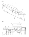
- FIG. 1 is a perspective view illustrating section steel marked by a printing unit according to the prior art
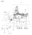
- FIG. 2 is a view illustrating the construction of a section steel cutting system having the printing unit according to the prior art
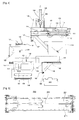
- FIG. 3 is a front elevation view illustrating a section steel cutting system according to an embodiment of the present invention.
- FIG. 4 is an exploded view for explaining the relationships between elements of the embodiment shown in FIG. 3 ;
- FIG. 5 is a plan view of a marking head assembly shown in FIG. 4 ;
- FIG. 6 is a front elevation view of a marking head assembly shown in FIG. 5 ;
- FIG. 7 is a cross sectional view taken along line B-B of FIG. 6 ;
- FIG. 8 is a cross sectional view taken along line C-C of FIG. 6 ;
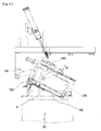
- FIGS. 9 to 11 are front elevation views for explaining the operational relationships between elements of the embodiment shown in FIG. 4 .
- FIG. 3 is a front elevation view illustrating a section steel cutting system shown in FIG. 2 according to an embodiment of the present invention
- FIG. 4 is an exploded view explaining the relationships between elements of the embodiment shown in FIG. 3
- FIG. 5 is a plan view of the marking head assembly shown in FIG. 4
- FIG. 6 is a front elevation view of the marking head assembly shown in FIG. 5
- FIG. 7 is a side elevation sectional view taken along line B-B of FIG. 6
- FIG. 8 is a plan sectional view taken along line C-C of FIG. 6
- FIGS. 9 to 11 are front elevation views explaining the operational relationships between elements of the embodiment shown in FIG. 4 .
- a marking apparatus of the present invention may be one of a plurality of modules or one of a plurality of components of a section steel cutting system shown in FIG. 2 , which is positioned in front of the cutting unit of the section steel cutting system.
- section steel cutting system is disclosed in Korean Patent Application No. 10-2007-0008683 commonly owned by the present applicant, and includes a designing system, an off-line programming (OLP) system, a monitoring system, a section steel input unit, a robot controller, and a reporting system.
- OTP off-line programming
- the robot controller serves to control a measuring robot 80 having a robot arm 81, a conveyor unit 90 having at least an infeeder conveyor, and a printing unit, all of which are organically associated.
- the measuring robot 80 receives the section steel A in the order of a working process according to the operation of the infeeder conveyor.
- the section steel A is arranged such that a relatively short part thereof faces a vertical conveyor roller 91 of the conveyor unit 90 and a relatively long part thereof (e.g., a printing surface) is slanted and disposed on a horizontal conveyor roller 92.
- a relatively short part thereof faces a vertical conveyor roller 91 of the conveyor unit 90
- a relatively long part thereof e.g., a printing surface
- the section steel is conveyed along the conveyor unit 90 while a bent part of the section steel faces upward.
- the section steel A has tens of defined dimensions according to the purpose and use thereof.
- the measuring robot 80 operates according to instructions from the above-mentioned robot controller.
- the measuring robot 80 checks the dimension and position of the received section steel A using the robot arm 81, moves the section steel A to the working position of the present embodiment P, carries out the setting for printing, and moves the section steel A in the X-axis direction during printing in association with the present embodiment P.
- the marking apparatus of the present embodiment P operates according to the instructions from the robot controller, and simultaneously marks a bending line, a frame line and a label onto the surface of the section steel A, in association with the measuring robot 80.
- the marking apparatus of the present embodiment P includes a carrier unit 100 for performing horizontal movement and rotation to correspond to the shape or kind of the section steel A, and a marking head assembly 200, having a plurality of rows of ink-jet heads, such as first, second and third ink-jet heads, which will be described later, which are installed on an end-side connection block of the carrier unit 100, so as to move or rotate close to the section steel A, and print a plurality of lines and labels without multiple marking steps.
- Each ink-jet head has a size large enough to come into surface contact with the greater part of the area of the large section steel A.
- the carrier unit 100 has a base frame 110, in which a plurality of axial members is erected parallel with each other on the ground, and a cantilever is coupled to an upper portion thereof.
- the base frame 110 is installed on the ground around the measuring robot 80 with respect to the position in front of the cutting unit of the section steel cutting system, and is preferably fixed on the ground so as to withstand the load applied.
- a hopper type waste-ink recovery section 111 which has an opening valve, such as a cock, is preferably installed on the base frame 110 below the marking head assembly 200.
- the cantilever 112 of the base frame 110 is provided with a first actuator 113 in the extension direction thereof so as to horizontally move the marking head assembly 200, as well as the elements for diverse movements or rotations, to the upper portion of the section steel A (see FIG. 3 ) to be marked.
- actuators to be mentioned later are controlled by the above-mentioned robot controller, and by nature of factory automation, they may of course be designed as a known reciprocal movement device (e.g., a known reciprocating device in which an electric motor, a ball-screw, a linear guide, a chain, a belt, a pulley, a shaft motor having a permanent magnet type shaft and a moving coil, a cable carrier, a hose, and so on are incorporated to achieve the reciprocal movement).
- a known reciprocating device e.g., a known reciprocating device in which an electric motor, a ball-screw, a linear guide, a chain, a belt, a pulley, a shaft motor having a permanent magnet type shaft and a moving coil, a cable carrier, a hose, and so on are incorporated to achieve the reciprocal movement.
- the first actuator 113 includes a cylinder fixed to the cantilever 112, an operating aim 114 reciprocally coupled to the inside of the cylinder, a linear rail 115, installed on the upper surface of the cantilever 112, and a plurality of linear blocks 116 sliding along the linear rail.
- a movable frame 120 is mounted on the linear blocks 116.
- the movable frame 120 includes a horizontal beam 121, supported by the linear blocks 116, an upper beam 122 extending upward from the upper surface of the left end side of the horizontal beam 121, and a lower beam 123, extending downward from the under surface of the left end side of the horizontal beam 121.
- the lower beam 123 is coupled, on its side, to the end of the operating arm 114 of the first actuator 113 so as to transmit the reciprocating force of the first actuator 113 to the movable frame 120.
- the movable frame 120 can be carried on the cantilever 112 of the base frame 110 by the linear blocks 116 and the linear rail 115.
- the first actuator 113 serves to horizontally move the marking head assembly 200 to the upper portion of the section steel.
- the upper beam 122 is provided on its side with a hinge joint 124.
- a middle portion of a cylinder of a second actuator 125 is hinged to the hinge joint 124.
- the second actuator 125 serves to primarily rotate the marking head assembly 200, which has been horizontally moved to the upper portion of the section steel, to thereby tilt it to correspond to the shape of the section steel.
- an operating arm 126 of the second actuator 125 is arranged to face a "y" shaped link member 130, and is coupled to an upper joint 131 of the link member 130.
- the link member 130 includes a center joint 132 of rotation in the left side and a connection joint 133 in the right side.
- the center joint 132 of the link member 130 is rotatably coupled to a bearing block 127, which is formed in the end portion of the lower beam 123 of the movable frame 120.
- the reciprocating movement of the operating arm 126 of the second actuator 125 allows the connection joint 133 of the link member 130 to rotate with respect to the center joint 132 of rotation and the bearing block 127.
- end side of a cylinder of a third actuator 140 is hinge-coupled near the upper joint 131 of the link member 130.
- the third actuator 140 serves to secondarily rotate the marking head assembly 200, which has been primarily tilted, so that the marking head assembly is secondarily tilted closer to the shape of the section steel.
- an operating arm 141 of the third actuator 140 is arranged to face a door-shaped support frame 150, and is coupled to a knuckle joint 152, which is eccentric from a connection joint-installation hole 151 of the support frame 150, in the right upper side direction with respect to the upper portion of the support frame 150.
- the support frame 150 is able to rotate together with the marking head assembly 200 and a hanger frame 160 to be described later, with respect to the connection joint 133 to be coupled with the installation hole 151.
- a plurality of linear blocks 153 is mounted on the support frame 150.
- a cylinder of a fourth actuator 154 is mounted in the upper left portion of the support frame 150.
- An operating arm 155 of the fourth actuator 154 is connected with the hanger frame 160.
- linear blocks 153 of the support frame 150 are coupled with a linear rail 161 of the hanger frame 160, so that the hanger frame 160 is movable according to the operation of the operation arm 155 of the fourth actuator 154.
- an end side connection block 162 is fixed on the hanger frame 160.
- At least one vertical guide roller 163 is further mounted so as to roll along the relatively short part of the section steel.
- a horizontal guide roller 158 which rolls along the relatively long part of the section steel, and a cover 159 are mounted.
- the support frame 150 or the hanger frame 160 be further provided with a plurality of proximity sensors 157 and 169 for detecting the control state of operation.
- the proximity sensor 169 mounted on the hanger frame 160, serves to detect the proximity state between the vertical guide roller 163 and the section steel.
- a LDS(laser distance sensor) may be used as the vertical and horizontal guide roller 163 and 158.
- the LDS can accurately and fastly measure the distance with the section steel without contacting the section steel. Measured data is used to control the support frame 150 and the hanger frame 160 to be guided along the section steel while maintaining predetermined distance.
- rollers may be disposed in the vicinity of the section steel near the LDS to prevent the LDS from colliding with the section steel by accident.
- the marking head assembly 200 has a hanger bracket 201, connected with the end side connection block 162 of FIG. 4 , which is described above.
- the hanger bracket 201 is an element having a cross-sectional shape resembling an inverted T, and corresponds to the base frame of the marking head assembly 200.
- the marking head assembly 200 includes single-dot type first and third ink-jet heads 210 and 230, arranged in a pair in opposite lower portions of the hanger bracket 201, and an 80-dot type second ink-jet head 220, disposed between the first and third ink-jet heads 210 and 230.
- the first, second, and the third ink-jet heads 210, 220, and 230 are adapted to perform the marking while being individually moved relative to the hanger bracket 201 by respective linear modules.
- the first and third ink-jet heads 210 and 230 use the known ball-screw assembly and linear guide, which are operated by the corresponding drive motors 211 and 231, as shown in FIG. 5 , and mark various lines in the state of being mounted on and moved via corresponding support members 212 and 232 of FIG. 7 , which are mounted on the moving block of the ball-screw assembly.
- the second ink-jet head 220 also uses the known ball-screw assembly and linear guide, which are directly connected with the corresponding drive motor 221 as shown in FIG. 7 or 8 , and marks labels or the like in a state of being mounted on and moved via corresponding support members 222 of FIG. 7 , which are mounted on the moving block of the ball-screw assembly.
- the measuring robot 80 sets the corresponding section steel A to an initial position, at which the marking starts, via the operation in combination with the conveyor unit 90.
- the carrier unit 100 is operated by the robot controller so as to horizontally move and rotate the marking head assembly 200 to bring it closer to the relatively long part of the section steel A.
- the first actuator 113 advances its operating arm 114 so as to horizontally move the movable frame 120 and all the elements mounted thereon, particularly such that the marking head assembly 200 is brought near the upper portion of the section steel A, as shown in FIG. 9 .
- the link member 130 connected with the operating arm 126 of the second actuator 125, is primarily rotated (T1) with respect to the center joint 132 of rotation, as shown in FIG. 10 .
- the horizontal guide roller 158 becomes closer to the relatively long part of the section steel A, whereas the vertical guide roller 163 may not become closer to the relatively short part of the section steel A.
- the third actuator 140 is natural for the third actuator 140 to be further operated so as to perform the secondary rotation T2 according to the type of the section steel A.
- the measuring robot moves the section steel A on the conveyor unit 90 from the initial position to the final position, at which the marking is done.
- the horizontal and vertical guide rollers 158 and 163 are driven while coming closer to the section steel A.
- the first, second, and third ink-jet heads of the marking head assembly 200 are simultaneously operated to carry out the marking of various lines and labels one time. Then, the link member 130 and the marking head assembly 200 are reversely rotated to return to their stand-by positions.
Landscapes
- Engineering & Computer Science (AREA)
- Manufacturing & Machinery (AREA)
- Mechanical Engineering (AREA)
- Life Sciences & Earth Sciences (AREA)
- Forests & Forestry (AREA)
- Ink Jet (AREA)
- Coating Apparatus (AREA)
- Spray Control Apparatus (AREA)
Description
- The present invention relates to a marking apparatus for use in a section steel cutting system.
- In general, section steel is reinforcing material which is used for vertical and horizontal structural reinforcement of a ship and in the top portion of a marine plant.
- In order to arrange and fix the reinforcing material on a structure of a ship in a desired form, a required process includes fabricating a plurality of pieces of section steel, having diverse dimensions or types, by cutting and welding a flat plate of steel, curve forming and/or cutting the fabricated section steel in a designated shape, sorting out the curve formed and/or cut section steel according to the installation position and the usage thereof, and transfering and storing the sorted section steel.
- Since the section steel to be used in a ship has to be attached to a curved hull part, the cutting process includes procedures of cutting the bent section steel to correspond to a design specification, marking a non-linear curve onto the surface of the section steel, bending the same using a bending machine such that the curved marked line is made linear. The non-linear section steel requiring the cutting process amounts to about 20% of whole section steel.
- In order to treat the great amount of the section steels, as shown in
FIG. 1 , in the cutting process, the section steel A is marked with a bending line A, various labels A2, and a frame line A3, using a coventional ink-jet type printing unit. - Referring to
FIG. 2 , there is shown aprinting unit 20 has been used in a section steel cutting system. For example, the section steel cutting system is for the section steel A, which is disclosed in Korean Patent Registration No.10-0633566 printing unit 20, further includes across conveyor 1, afeeding roller 2, acarrier unit 10, acutting unit 30, and acontrol room 50 having acontrol circuit 40. - Here, the
cross conveyor 1 conveys the section steel A onto thefeeding roller 2, and thecarrier unit 10 carries the conveyed section steel A in the longitudinal direction of the section steel A to a cutting position. - The
printing unit 20 carries out a marking process via the multiple marking steps, so as to form, on the section steel A, various printed marks including a bending line. - The
printing unit 20 implements multi-axis movement, as in a multi-axis robot. For reference, the directions of the multi-axis movement are defined as follows: the X-axis direction of the multi-axis designates the feeding direction of the section steel A by thefeeding roller 2, the Y-axis direction designates a direction perpendicular to the X-axis direction and corresponding to the width direction of the section steel A, and the Z-axis direction designates the direction perpendicular to the X-Y plane and corresponding to the height direction of the cutting system. - However, the printing unit of the conventional section steel cutting system has defects of very slow working speed and reduced efficiency because a relatively great number of marking steps, such as line-printing operations (for a bending line, a frame line or the like), and label-printing operations must be carried out.
- Further, in the conventional section steel cutting system, taking account of the fact that the section steel is arranged and carried such that a bent portion thereof faces upward according to its shape or type, the printing has to be performed onto an inclined surface of the section steel. However, since a separate complicated carrier device for erecting the section steel vertically is used so that the section steel corresponds to a printer head of the printing unit, working efficiency is degraded, and the section steel is not brought very close to the printer head, thereby greatly seducing marking precision and printing quality.
US 2007/0095218 A1 discloses an assembly for marking a pole transported by a conveyor, comprising a support frame located adjacent to at least a portion of the conveyor and at least one print head assembly for marking the pole, the at least one print head assembly including at least one print head, and wherein the at least one print head is moveably secured to the frame for selectively engaging the pole. - An object of the present invention is to provide a marking apparatus of a section steel cutting system, in which a marking head assembly, having plural rows of ink-jet heads, is positioned close to a carrier unit according to the type of section steel, thereby implementing the marking in only one transportation step without requiring multiple marking steps.
- In accordance with an embodyment of the present invention, there is provided a marking apparatus for use in a section steel cutting system having a measuring robot and a conveyor unit, as disclosed in
claim 1. - According to the present invention as set forth above, the marking apparatus of the section steel cutting system has the carrier unit and the marking head assembly, which carry out the marking operation for various lines, labels, and the like after being moved
and rotated to correspond to the shape of the section steel, so that the marking is simultaneously done with a plurality of ink-jet heads, providing very rapid working speed and high working efficiency. - Further, the marking can be performed so as to correspond to diverse shapes of section steel even when using only the present cutting system via the primary rotation by a second actuator or the secondary rotation by a third actuator, to correspond to the shape of the printing surface of the section steel, which is arranged and carried. In particular, the marking accuracy and the printing quality are very high since the marking is done in the state in which vertical and horizontal guide rollers are driven while contacting the section steel.
- The above and other objects and features of the present invention will become apparent from the following description of embodiments given in conjunction with the accompanying drawings, in which:
-
FIG. 1 is a perspective view illustrating section steel marked by a printing unit according to the prior art; -
FIG. 2 is a view illustrating the construction of a section steel cutting system having the printing unit according to the prior art; -
FIG. 3 is a front elevation view illustrating a section steel cutting system according to an embodiment of the present invention; -
FIG. 4 is an exploded view for explaining the relationships between elements of the embodiment shown inFIG. 3 ; -
FIG. 5 is a plan view of a marking head assembly shown inFIG. 4 ; -
FIG. 6 is a front elevation view of a marking head assembly shown inFIG. 5 ; -
FIG. 7 is a cross sectional view taken along line B-B ofFIG. 6 ; -
FIG. 8 is a cross sectional view taken along line C-C ofFIG. 6 ; and -
FIGS. 9 to 11 are front elevation views for explaining the operational relationships between elements of the embodiment shown inFIG. 4 . - Hereinafter, a detailed description will be made of exemplary embodiments of the present invention with reference to the drawings.
-
FIG. 3 is a front elevation view illustrating a section steel cutting system shown inFIG. 2 according to an embodiment of the present invention,FIG. 4 is an exploded view explaining the relationships between elements of the embodiment shown inFIG. 3 ,FIG. 5 is a plan view of the marking head assembly shown inFIG. 4 , andFIG. 6 is a front elevation view of the marking head assembly shown inFIG. 5 . Further,FIG. 7 is a side elevation sectional view taken along line B-B ofFIG. 6 ,FIG. 8 is a plan sectional view taken along line C-C ofFIG. 6 , andFIGS. 9 to 11 are front elevation views explaining the operational relationships between elements of the embodiment shown inFIG. 4 . - As shown in
FIG. 3 , a marking apparatus of the present invention may be one of a plurality of modules or one of a plurality of components of a section steel cutting system shown inFIG. 2 , which is positioned in front of the cutting unit of the section steel cutting system. - As example of the section steel cutting system is disclosed in Korean Patent Application No.
10-2007-0008683 - The robot controller serves to control a measuring
robot 80 having a robot arm 81, aconveyor unit 90 having at least an infeeder conveyor, and a printing unit, all of which are organically associated. - Before the detailed description, the portion related to the general technology will now be described.
- The
measuring robot 80 receives the section steel A in the order of a working process according to the operation of the infeeder conveyor. - The section steel A is arranged such that a relatively short part thereof faces a
vertical conveyor roller 91 of theconveyor unit 90 and a relatively long part thereof (e.g., a printing surface) is slanted and disposed on ahorizontal conveyor roller 92. Thus, the section steel is conveyed along theconveyor unit 90 while a bent part of the section steel faces upward. - The section steel A has tens of defined dimensions according to the purpose and use thereof.
- In the meantime, the
measuring robot 80 operates according to instructions from the above-mentioned robot controller. - The
measuring robot 80 checks the dimension and position of the received section steel A using the robot arm 81, moves the section steel A to the working position of the present embodiment P, carries out the setting for printing, and moves the section steel A in the X-axis direction during printing in association with the present embodiment P. - The marking apparatus of the present embodiment P operates according to the instructions from the robot controller, and simultaneously marks a bending line, a frame line and a label onto the surface of the section steel A, in association with the
measuring robot 80. - To this end, the marking apparatus of the present embodiment P includes a
carrier unit 100 for performing horizontal movement and rotation to correspond to the shape or kind of the section steel A, and amarking head assembly 200, having a plurality of rows of ink-jet heads, such as first, second and third ink-jet heads, which will be described later, which are installed on an end-side connection block of thecarrier unit 100, so as to move or rotate close to the section steel A, and print a plurality of lines and labels without multiple marking steps. - Each ink-jet head has a size large enough to come into surface contact with the greater part of the area of the large section steel A.
- First, the
carrier unit 100 has abase frame 110, in which a plurality of axial members is erected parallel with each other on the ground, and a cantilever is coupled to an upper portion thereof. - Here, the
base frame 110 is installed on the ground around themeasuring robot 80 with respect to the position in front of the cutting unit of the section steel cutting system, and is preferably fixed on the ground so as to withstand the load applied. - In order to collect discharged ink during maintenance, cleaning or the like, by nature of the ink-jet printing, a hopper type waste-
ink recovery section 111, which has an opening valve, such as a cock, is preferably installed on thebase frame 110 below themarking head assembly 200. - The relationships between elements of the present embodiment P will now be described with reference to
FIG. 4 . - As illustrated in
FIG. 4 , thecantilever 112 of thebase frame 110 is provided with afirst actuator 113 in the extension direction thereof so as to horizontally move themarking head assembly 200, as well as the elements for diverse movements or rotations, to the upper portion of the section steel A (seeFIG. 3 ) to be marked. - All of the actuators to be mentioned later, including the
first actuator 113, are controlled by the above-mentioned robot controller, and by nature of factory automation, they may of course be designed as a known reciprocal movement device (e.g., a known reciprocating device in which an electric motor, a ball-screw, a linear guide, a chain, a belt, a pulley, a shaft motor having a permanent magnet type shaft and a moving coil, a cable carrier, a hose, and so on are incorporated to achieve the reciprocal movement). - For example, the
first actuator 113 includes a cylinder fixed to thecantilever 112, anoperating aim 114 reciprocally coupled to the inside of the cylinder, alinear rail 115, installed on the upper surface of thecantilever 112, and a plurality oflinear blocks 116 sliding along the linear rail. - A
movable frame 120 is mounted on thelinear blocks 116. - The
movable frame 120 includes ahorizontal beam 121, supported by thelinear blocks 116, anupper beam 122 extending upward from the upper surface of the left end side of thehorizontal beam 121, and alower beam 123, extending downward from the under surface of the left end side of thehorizontal beam 121. - The
lower beam 123 is coupled, on its side, to the end of theoperating arm 114 of thefirst actuator 113 so as to transmit the reciprocating force of thefirst actuator 113 to themovable frame 120. - In this case, the
movable frame 120 can be carried on thecantilever 112 of thebase frame 110 by thelinear blocks 116 and thelinear rail 115. - In view of the above, the
first actuator 113 serves to horizontally move the markinghead assembly 200 to the upper portion of the section steel. - Meanwhile, the
upper beam 122 is provided on its side with ahinge joint 124. - A middle portion of a cylinder of a
second actuator 125 is hinged to thehinge joint 124. - The
second actuator 125 serves to primarily rotate the markinghead assembly 200, which has been horizontally moved to the upper portion of the section steel, to thereby tilt it to correspond to the shape of the section steel. - To this end, an
operating arm 126 of thesecond actuator 125 is arranged to face a "y" shapedlink member 130, and is coupled to anupper joint 131 of thelink member 130. - The
link member 130 includes acenter joint 132 of rotation in the left side and a connection joint 133 in the right side. - The
center joint 132 of thelink member 130 is rotatably coupled to abearing block 127, which is formed in the end portion of thelower beam 123 of themovable frame 120. - The reciprocating movement of the
operating arm 126 of thesecond actuator 125 allows theconnection joint 133 of thelink member 130 to rotate with respect to thecenter joint 132 of rotation and thebearing block 127. - Further, the end side of a cylinder of a
third actuator 140 is hinge-coupled near theupper joint 131 of thelink member 130. - The
third actuator 140 serves to secondarily rotate the markinghead assembly 200, which has been primarily tilted, so that the marking head assembly is secondarily tilted closer to the shape of the section steel. - To this end, an
operating arm 141 of thethird actuator 140 is arranged to face a door-shapedsupport frame 150, and is coupled to aknuckle joint 152, which is eccentric from a connection joint-installation hole 151 of thesupport frame 150, in the right upper side direction with respect to the upper portion of thesupport frame 150. - The
support frame 150 is able to rotate together with the markinghead assembly 200 and ahanger frame 160 to be described later, with respect to the connection joint 133 to be coupled with theinstallation hole 151. - A plurality of
linear blocks 153 is mounted on thesupport frame 150. - In the upper left portion of the
support frame 150, a cylinder of afourth actuator 154 is mounted. - An
operating arm 155 of thefourth actuator 154 is connected with thehanger frame 160. - Here, the
linear blocks 153 of thesupport frame 150 are coupled with alinear rail 161 of thehanger frame 160, so that thehanger frame 160 is movable according to the operation of theoperation arm 155 of thefourth actuator 154. - On the
hanger frame 160, an endside connection block 162, as mentioned above, is fixed. - Further, in the lower portion, or in the left lower portion, more preferably, of the
hanger frame 160, at least onevertical guide roller 163 is further mounted so as to roll along the relatively short part of the section steel. - Furthermore, in the lower portion of the
support frame 150, ahorizontal guide roller 158, which rolls along the relatively long part of the section steel, and acover 159 are mounted. - It is preferable that the
support frame 150 or thehanger frame 160 be further provided with a plurality ofproximity sensors - For example, the
proximity sensor 169, mounted on thehanger frame 160, serves to detect the proximity state between thevertical guide roller 163 and the section steel. - Alternatively, a LDS(laser distance sensor) may be used as the vertical and
horizontal guide roller support frame 150 and thehanger frame 160 to be guided along the section steel while maintaining predetermined distance. In this case, rollers may be disposed in the vicinity of the section steel near the LDS to prevent the LDS from colliding with the section steel by accident. - Referring to
FIGS. 5 and6 , the markinghead assembly 200 has ahanger bracket 201, connected with the end side connection block 162 ofFIG. 4 , which is described above. - The
hanger bracket 201 is an element having a cross-sectional shape resembling an inverted T, and corresponds to the base frame of the markinghead assembly 200. - The marking
head assembly 200 includes single-dot type first and third ink-jet heads 210 and 230, arranged in a pair in opposite lower portions of thehanger bracket 201, and an 80-dot type second ink-jet head 220, disposed between the first and third ink-jet heads 210 and 230. - The first, second, and the third ink-jet heads 210, 220, and 230 are adapted to perform the marking while being individually moved relative to the
hanger bracket 201 by respective linear modules. - As for the linear module, for example, the first and third ink-jet heads 210 and 230 use the known ball-screw assembly and linear guide, which are operated by the corresponding
drive motors FIG. 5 , and mark various lines in the state of being mounted on and moved via correspondingsupport members 212 and 232 ofFIG. 7 , which are mounted on the moving block of the ball-screw assembly. - Further, the second ink-
jet head 220 also uses the known ball-screw assembly and linear guide, which are directly connected with thecorresponding drive motor 221 as shown inFIG. 7 or 8 , and marks labels or the like in a state of being mounted on and moved via correspondingsupport members 222 ofFIG. 7 , which are mounted on the moving block of the ball-screw assembly. - Now the operational relationships between elements of the present invention will be described with reference to
FIGS. 3 ,4 , and9 to 11 . - First, as shown in
FIG. 3 , the measuringrobot 80 sets the corresponding section steel A to an initial position, at which the marking starts, via the operation in combination with theconveyor unit 90. - Then, the
carrier unit 100 is operated by the robot controller so as to horizontally move and rotate the markinghead assembly 200 to bring it closer to the relatively long part of the section steel A. - To be specific, the
first actuator 113, shown inFIG. 4 , advances itsoperating arm 114 so as to horizontally move themovable frame 120 and all the elements mounted thereon, particularly such that the markinghead assembly 200 is brought near the upper portion of the section steel A, as shown inFIG. 9 . - In
FIG. 9 , then thesecond actuator 125 also advances its operating arm downward. - In this case, the
link member 130, connected with theoperating arm 126 of thesecond actuator 125, is primarily rotated (T1) with respect to thecenter joint 132 of rotation, as shown inFIG. 10 . - In
FIG. 10 , thehorizontal guide roller 158 becomes closer to the relatively long part of the section steel A, whereas thevertical guide roller 163 may not become closer to the relatively short part of the section steel A. - In this case, as the
fourth actuator 154 stops using the correspondingproximity sensor 169 after the operation F, theentire hanger frame 160 supported by thesupport frame 150 is finally moved so that thevertical guide roller 163 also comes closer to the relatively short part of the section steel A, as shown inFIG. 11 . - Further, it is natural for the
third actuator 140 to be further operated so as to perform the secondary rotation T2 according to the type of the section steel A. - In this state, the measuring robot moves the section steel A on the
conveyor unit 90 from the initial position to the final position, at which the marking is done. In the course of a single movement step, the horizontal andvertical guide rollers head assembly 200 are simultaneously operated to carry out the marking of various lines and labels one time. Then, thelink member 130 and the markinghead assembly 200 are reversely rotated to return to their stand-by positions. - Although preferred embodiments of the present invention have been described for illustrative purposes, those skilled in the art will appreciate that various modifications, additions and substitutions are possible, without departing from the scope of the invention as disclosed in the accompanying claims.
Claims (8)
- A marking apparatus for use in a section steel cutting system, including a measuring robot (80) and a conveyor unit (90), the marking apparatus comprising:a carrier unit (100) for performing the horizontal movement and rotation to correspond to a shape of a section steel (A) on the conveyor unit (90);and a marking head assembly (200) mounted on an end portion connection block of the carrier unit (100) and having a plurality of ink-jet heads (210, 220, 230) for performing a printing at a closer position to the section steel (A), wherein the carrier unit (100) comprises:a base frame (110) mounted on ground around the measuring robot (80);a movable frame (120), horizontally movable based on the base frame (110) ;a first actuator (113) for operating the movable frame (120);a second actuator (125), hinged to an upper portion of the movable frame (120);a link member (130), coupled with an operating arm (126) of the second actuator (125) so as to be rotated with respect to a center joint (132) of rotation, hinged to a lower portion of the movable frame (120);a support frame (150), coupled via a connection joint (133), formed in the link member (130);a fourth actuator (154) mounted in an upper left portion of the support frame (150); anda hanger frame (160), coupled with an operating arm (155) of the fourth actuator (154) so as to horizontally move based on the support frame (150), and having the end portion connection block for mounting the marking head (200) assembly.
- The marking apparatus according to claim 1, wherein the carrier unit (100) further comprises a third actuator (140), coupled between the link member (130) and the support frame (150), using a knuckle joint of the support frame (150).
- The marking apparatus according to claim 1, wherein the carrier unit (100) further comprises a horizontal guide roller (158), mounted on the lower portion of the support frame (150) to roll along a relatively long part of the section steel (A).
- The marking apparatus according to claim 3, wherein the horizontal guide roller (158) includes one or more laser distance sensors (LDSs).
- The marking apparatus according to claim 1, wherein the carrier unit (100) further comprising at least one vertical guide roller (163), mounted on the lower portion of the hanger frame (160) so as to roll along a relatively short part of the section steel (A).
- The marking apparatus according to claim 5, wherein the vertical guide roller (163) includes one or more laser distance sensors (LDSs).
- The marking apparatus according to claim 1, wherein the marking head assembly (200) further comprises: a hanger bracket (201), connected with the end portion connection block; and a plurality of linear modules (211, 221, 231), coupled so as to individually move the the plurality of ink-jet heads (210, 220, 230), based on the hanger bracket (201).
- The marking apparatus according to claim 1, wherein the plurality of ink-jet heads includes: first (210) and third (230) ink-jet heads of single-dot type, disposed in a pair arrangement in opposite lower portions of the hanger bracket (201); and a second ink-jet head (220) of multi-dot type, disposed between the first (210) and third (230) ink- jet heads.
Applications Claiming Priority (2)
| Application Number | Priority Date | Filing Date | Title |
|---|---|---|---|
| KR1020070055698A KR100868232B1 (en) | 2007-06-07 | 2007-06-07 | Marking device for section steel cutting system |
| PCT/KR2008/003205 WO2008150143A2 (en) | 2007-06-07 | 2008-06-09 | Marking apparatus for use in section steel cutting system |
Publications (3)
| Publication Number | Publication Date |
|---|---|
| EP2150381A2 EP2150381A2 (en) | 2010-02-10 |
| EP2150381A4 EP2150381A4 (en) | 2011-10-19 |
| EP2150381B1 true EP2150381B1 (en) | 2012-11-21 |
Family
ID=40094313
Family Applications (1)
| Application Number | Title | Priority Date | Filing Date |
|---|---|---|---|
| EP08766167A Not-in-force EP2150381B1 (en) | 2007-06-07 | 2008-06-09 | Marking apparatus for use in section steel cutting system |
Country Status (5)
| Country | Link |
|---|---|
| EP (1) | EP2150381B1 (en) |
| JP (1) | JP5025793B2 (en) |
| KR (1) | KR100868232B1 (en) |
| CN (1) | CN101678550B (en) |
| WO (1) | WO2008150143A2 (en) |
Families Citing this family (10)
| Publication number | Priority date | Publication date | Assignee | Title |
|---|---|---|---|---|
| CN102393675A (en) * | 2011-09-23 | 2012-03-28 | 成都焊研威达科技股份有限公司 | Robot off-line section steel linear cutting software system |
| KR101356285B1 (en) * | 2012-07-26 | 2014-01-29 | 주식회사 현대미포조선 | Apparatus and method for controlling of print of section shape steel's management information |
| KR101248128B1 (en) | 2012-11-16 | 2013-03-26 | 주식회사 윈텍오토메이션 | Handling device and the installation structure for cemented carbides |
| KR101644637B1 (en) * | 2014-08-29 | 2016-08-12 | 주식회사 세광하이테크 | Marking and cutting device for hose |
| CN106274055B (en) * | 2016-09-08 | 2018-09-18 | 四川福蓉科技股份公司 | A kind of full-automatic ink spraying marking device |
| CN106531367A (en) * | 2016-11-10 | 2017-03-22 | 无锡威格斯电气有限公司 | Wire marking device |
| BE1026112B1 (en) | 2018-02-26 | 2019-10-17 | Bke-Machines International Sa | Tracing on a sheet metal intended for boilermaking use |
| KR102097374B1 (en) | 2019-12-20 | 2020-04-06 | 주식회사 미주산업 | Automated system for marking and cutting of pipe support |
| CN114523460B (en) * | 2022-03-18 | 2024-04-02 | 浙江城乡美学创意发展有限公司 | Line drawing device convenient to building site uses |
| CN119116560A (en) * | 2024-08-29 | 2024-12-13 | 上海中船临港船舶装备有限公司 | A multifunctional inkjet coding and marking device and inkjet printing method |
Family Cites Families (11)
| Publication number | Priority date | Publication date | Assignee | Title |
|---|---|---|---|---|
| JPS6389352A (en) * | 1986-10-01 | 1988-04-20 | Kawasaki Steel Corp | Printing method and apparatus |
| JPH023309A (en) * | 1988-06-17 | 1990-01-08 | Sumitomo Metal Ind Ltd | Method and apparatus for printing on surface of steel material |
| CN2046794U (en) * | 1989-01-12 | 1989-11-01 | 胡昌明 | Universal drawing instrument for pipe elbow |
| JP2736604B2 (en) * | 1994-03-23 | 1998-04-02 | 川崎重工業株式会社 | Scoring device |
| KR0148874B1 (en) * | 1995-05-09 | 1998-12-01 | 김정국 | Tool assembly for multi-heads of ink-jet printer for large character |
| JP3771323B2 (en) * | 1995-07-27 | 2006-04-26 | 株式会社アマダ | Shape steel processing machine |
| JPH11207664A (en) * | 1998-01-22 | 1999-08-03 | Koike Sanso Kogyo Co Ltd | Marking device |
| KR100633566B1 (en) | 2004-10-19 | 2006-10-16 | 삼성중공업 주식회사 | Band line marking device installed in the steel cutting device and its control method |
| US20070095218A1 (en) * | 2005-10-31 | 2007-05-03 | Thomas & Betts International, Inc. | Pole marking system for improved manufacturing process |
| KR100700047B1 (en) * | 2005-12-30 | 2007-03-28 | 경신공업 주식회사 | Nut fastening device for stud bolt in junction box |
| KR200426461Y1 (en) * | 2006-05-04 | 2006-09-18 | 주식회사 아이티앤티 | Universal dot marking device used in various materials |
-
2007
- 2007-06-07 KR KR1020070055698A patent/KR100868232B1/en not_active Expired - Fee Related
-
2008
- 2008-06-09 EP EP08766167A patent/EP2150381B1/en not_active Not-in-force
- 2008-06-09 CN CN2008800188047A patent/CN101678550B/en not_active Expired - Fee Related
- 2008-06-09 JP JP2010511126A patent/JP5025793B2/en not_active Expired - Fee Related
- 2008-06-09 WO PCT/KR2008/003205 patent/WO2008150143A2/en not_active Ceased
Also Published As
| Publication number | Publication date |
|---|---|
| KR100868232B1 (en) | 2008-11-12 |
| JP2010528883A (en) | 2010-08-26 |
| EP2150381A2 (en) | 2010-02-10 |
| WO2008150143A2 (en) | 2008-12-11 |
| EP2150381A4 (en) | 2011-10-19 |
| CN101678550A (en) | 2010-03-24 |
| JP5025793B2 (en) | 2012-09-12 |
| WO2008150143A3 (en) | 2009-02-05 |
| CN101678550B (en) | 2011-07-13 |
Similar Documents
| Publication | Publication Date | Title |
|---|---|---|
| JP5025793B2 (en) | Marking device for section cutting system | |
| CA1273843A (en) | Multiple movement marking machine | |
| US8424359B2 (en) | Bending press with a loading device and method for its operation | |
| KR100894354B1 (en) | Labeling system of a steel material | |
| CN101450553A (en) | Device for refining workpiece | |
| KR20100044386A (en) | Thickness measuring device of steel sheet | |
| JP2832312B2 (en) | Printing device | |
| CN101829725B (en) | Production line and process for punching U-shaped beam | |
| KR100926517B1 (en) | Printing device for steel sheet | |
| KR100880897B1 (en) | Marking device and signal processing method with multi-axis encoder assembly | |
| KR100637001B1 (en) | Automatic Marking and Cutting Device | |
| CN101654156B (en) | Labelling machine | |
| KR20120042210A (en) | Apparatus for automatic marking welding baseline of face plate | |
| US20060162519A1 (en) | Positioning system and carriage assembly for converting machines | |
| CN219585235U (en) | Overturning positioning detection mechanism | |
| CN221050692U (en) | Automobile body-in-white workpiece feeding accumulation chain | |
| CN220641428U (en) | Cutting platform | |
| DE69327606T2 (en) | Method of identifying roles and apparatus for performing them | |
| KR20070095534A (en) | Clamping device for body transfer bogie | |
| KR20140036521A (en) | Auto printing apparatus for moving object and marking method thereof | |
| KR102916477B1 (en) | Reinforcement handling robot system | |
| KR102916478B1 (en) | Reinforcement handling robot system | |
| JP4725486B2 (en) | Welding robot | |
| CN223045411U (en) | A fully automatic inkjet machine tool for liquefied petroleum gas cylinders | |
| JP2021109422A (en) | Printer and printing facility |
Legal Events
| Date | Code | Title | Description |
|---|---|---|---|
| PUAI | Public reference made under article 153(3) epc to a published international application that has entered the european phase |
Free format text: ORIGINAL CODE: 0009012 |
|
| 17P | Request for examination filed |
Effective date: 20091103 |
|
| AK | Designated contracting states |
Kind code of ref document: A2 Designated state(s): AT BE BG CH CY CZ DE DK EE ES FI FR GB GR HR HU IE IS IT LI LT LU LV MC MT NL NO PL PT RO SE SI SK TR |
|
| AX | Request for extension of the european patent |
Extension state: AL BA MK RS |
|
| A4 | Supplementary search report drawn up and despatched |
Effective date: 20110921 |
|
| RIC1 | Information provided on ipc code assigned before grant |
Ipc: B25H 7/04 20060101AFI20110915BHEP |
|
| GRAP | Despatch of communication of intention to grant a patent |
Free format text: ORIGINAL CODE: EPIDOSNIGR1 |
|
| DAX | Request for extension of the european patent (deleted) | ||
| GRAS | Grant fee paid |
Free format text: ORIGINAL CODE: EPIDOSNIGR3 |
|
| GRAA | (expected) grant |
Free format text: ORIGINAL CODE: 0009210 |
|
| AK | Designated contracting states |
Kind code of ref document: B1 Designated state(s): AT BE BG CH CY CZ DE DK EE ES FI FR GB GR HR HU IE IS IT LI LT LU LV MC MT NL NO PL PT RO SE SI SK TR |
|
| REG | Reference to a national code |
Ref country code: GB Ref legal event code: FG4D |
|
| REG | Reference to a national code |
Ref country code: CH Ref legal event code: EP |
|
| REG | Reference to a national code |
Ref country code: AT Ref legal event code: REF Ref document number: 584801 Country of ref document: AT Kind code of ref document: T Effective date: 20121215 |
|
| REG | Reference to a national code |
Ref country code: IE Ref legal event code: FG4D |
|
| REG | Reference to a national code |
Ref country code: DE Ref legal event code: R096 Ref document number: 602008020273 Country of ref document: DE Effective date: 20130117 |
|
| REG | Reference to a national code |
Ref country code: NL Ref legal event code: T3 |
|
| REG | Reference to a national code |
Ref country code: AT Ref legal event code: MK05 Ref document number: 584801 Country of ref document: AT Kind code of ref document: T Effective date: 20121121 |
|
| REG | Reference to a national code |
Ref country code: LT Ref legal event code: MG4D |
|
| PG25 | Lapsed in a contracting state [announced via postgrant information from national office to epo] |
Ref country code: LT Free format text: LAPSE BECAUSE OF FAILURE TO SUBMIT A TRANSLATION OF THE DESCRIPTION OR TO PAY THE FEE WITHIN THE PRESCRIBED TIME-LIMIT Effective date: 20121121 Ref country code: FI Free format text: LAPSE BECAUSE OF FAILURE TO SUBMIT A TRANSLATION OF THE DESCRIPTION OR TO PAY THE FEE WITHIN THE PRESCRIBED TIME-LIMIT Effective date: 20121121 Ref country code: HR Free format text: LAPSE BECAUSE OF FAILURE TO SUBMIT A TRANSLATION OF THE DESCRIPTION OR TO PAY THE FEE WITHIN THE PRESCRIBED TIME-LIMIT Effective date: 20121121 Ref country code: SE Free format text: LAPSE BECAUSE OF FAILURE TO SUBMIT A TRANSLATION OF THE DESCRIPTION OR TO PAY THE FEE WITHIN THE PRESCRIBED TIME-LIMIT Effective date: 20121121 Ref country code: NO Free format text: LAPSE BECAUSE OF FAILURE TO SUBMIT A TRANSLATION OF THE DESCRIPTION OR TO PAY THE FEE WITHIN THE PRESCRIBED TIME-LIMIT Effective date: 20130221 Ref country code: ES Free format text: LAPSE BECAUSE OF FAILURE TO SUBMIT A TRANSLATION OF THE DESCRIPTION OR TO PAY THE FEE WITHIN THE PRESCRIBED TIME-LIMIT Effective date: 20130304 |
|
| PG25 | Lapsed in a contracting state [announced via postgrant information from national office to epo] |
Ref country code: BE Free format text: LAPSE BECAUSE OF FAILURE TO SUBMIT A TRANSLATION OF THE DESCRIPTION OR TO PAY THE FEE WITHIN THE PRESCRIBED TIME-LIMIT Effective date: 20121121 Ref country code: PL Free format text: LAPSE BECAUSE OF FAILURE TO SUBMIT A TRANSLATION OF THE DESCRIPTION OR TO PAY THE FEE WITHIN THE PRESCRIBED TIME-LIMIT Effective date: 20121121 Ref country code: SI Free format text: LAPSE BECAUSE OF FAILURE TO SUBMIT A TRANSLATION OF THE DESCRIPTION OR TO PAY THE FEE WITHIN THE PRESCRIBED TIME-LIMIT Effective date: 20121121 Ref country code: GR Free format text: LAPSE BECAUSE OF FAILURE TO SUBMIT A TRANSLATION OF THE DESCRIPTION OR TO PAY THE FEE WITHIN THE PRESCRIBED TIME-LIMIT Effective date: 20130222 Ref country code: PT Free format text: LAPSE BECAUSE OF FAILURE TO SUBMIT A TRANSLATION OF THE DESCRIPTION OR TO PAY THE FEE WITHIN THE PRESCRIBED TIME-LIMIT Effective date: 20130321 Ref country code: LV Free format text: LAPSE BECAUSE OF FAILURE TO SUBMIT A TRANSLATION OF THE DESCRIPTION OR TO PAY THE FEE WITHIN THE PRESCRIBED TIME-LIMIT Effective date: 20121121 |
|
| PG25 | Lapsed in a contracting state [announced via postgrant information from national office to epo] |
Ref country code: AT Free format text: LAPSE BECAUSE OF FAILURE TO SUBMIT A TRANSLATION OF THE DESCRIPTION OR TO PAY THE FEE WITHIN THE PRESCRIBED TIME-LIMIT Effective date: 20121121 |
|
| PG25 | Lapsed in a contracting state [announced via postgrant information from national office to epo] |
Ref country code: CZ Free format text: LAPSE BECAUSE OF FAILURE TO SUBMIT A TRANSLATION OF THE DESCRIPTION OR TO PAY THE FEE WITHIN THE PRESCRIBED TIME-LIMIT Effective date: 20121121 Ref country code: SK Free format text: LAPSE BECAUSE OF FAILURE TO SUBMIT A TRANSLATION OF THE DESCRIPTION OR TO PAY THE FEE WITHIN THE PRESCRIBED TIME-LIMIT Effective date: 20121121 Ref country code: BG Free format text: LAPSE BECAUSE OF FAILURE TO SUBMIT A TRANSLATION OF THE DESCRIPTION OR TO PAY THE FEE WITHIN THE PRESCRIBED TIME-LIMIT Effective date: 20130221 Ref country code: DK Free format text: LAPSE BECAUSE OF FAILURE TO SUBMIT A TRANSLATION OF THE DESCRIPTION OR TO PAY THE FEE WITHIN THE PRESCRIBED TIME-LIMIT Effective date: 20121121 Ref country code: EE Free format text: LAPSE BECAUSE OF FAILURE TO SUBMIT A TRANSLATION OF THE DESCRIPTION OR TO PAY THE FEE WITHIN THE PRESCRIBED TIME-LIMIT Effective date: 20121121 |
|
| PG25 | Lapsed in a contracting state [announced via postgrant information from national office to epo] |
Ref country code: RO Free format text: LAPSE BECAUSE OF FAILURE TO SUBMIT A TRANSLATION OF THE DESCRIPTION OR TO PAY THE FEE WITHIN THE PRESCRIBED TIME-LIMIT Effective date: 20121121 Ref country code: IT Free format text: LAPSE BECAUSE OF FAILURE TO SUBMIT A TRANSLATION OF THE DESCRIPTION OR TO PAY THE FEE WITHIN THE PRESCRIBED TIME-LIMIT Effective date: 20121121 |
|
| PLBE | No opposition filed within time limit |
Free format text: ORIGINAL CODE: 0009261 |
|
| STAA | Information on the status of an ep patent application or granted ep patent |
Free format text: STATUS: NO OPPOSITION FILED WITHIN TIME LIMIT |
|
| 26N | No opposition filed |
Effective date: 20130822 |
|
| REG | Reference to a national code |
Ref country code: DE Ref legal event code: R097 Ref document number: 602008020273 Country of ref document: DE Effective date: 20130822 |
|
| PG25 | Lapsed in a contracting state [announced via postgrant information from national office to epo] |
Ref country code: MC Free format text: LAPSE BECAUSE OF FAILURE TO SUBMIT A TRANSLATION OF THE DESCRIPTION OR TO PAY THE FEE WITHIN THE PRESCRIBED TIME-LIMIT Effective date: 20121121 |
|
| REG | Reference to a national code |
Ref country code: CH Ref legal event code: PL |
|
| GBPC | Gb: european patent ceased through non-payment of renewal fee |
Effective date: 20130609 |
|
| REG | Reference to a national code |
Ref country code: IE Ref legal event code: MM4A |
|
| REG | Reference to a national code |
Ref country code: FR Ref legal event code: ST Effective date: 20140228 |
|
| PG25 | Lapsed in a contracting state [announced via postgrant information from national office to epo] |
Ref country code: LI Free format text: LAPSE BECAUSE OF NON-PAYMENT OF DUE FEES Effective date: 20130630 Ref country code: CH Free format text: LAPSE BECAUSE OF NON-PAYMENT OF DUE FEES Effective date: 20130630 Ref country code: GB Free format text: LAPSE BECAUSE OF NON-PAYMENT OF DUE FEES Effective date: 20130609 Ref country code: IE Free format text: LAPSE BECAUSE OF NON-PAYMENT OF DUE FEES Effective date: 20130609 |
|
| PG25 | Lapsed in a contracting state [announced via postgrant information from national office to epo] |
Ref country code: FR Free format text: LAPSE BECAUSE OF NON-PAYMENT OF DUE FEES Effective date: 20130701 |
|
| PGFP | Annual fee paid to national office [announced via postgrant information from national office to epo] |
Ref country code: DE Payment date: 20140523 Year of fee payment: 7 Ref country code: NL Payment date: 20140522 Year of fee payment: 7 |
|
| PG25 | Lapsed in a contracting state [announced via postgrant information from national office to epo] |
Ref country code: MT Free format text: LAPSE BECAUSE OF FAILURE TO SUBMIT A TRANSLATION OF THE DESCRIPTION OR TO PAY THE FEE WITHIN THE PRESCRIBED TIME-LIMIT Effective date: 20121121 |
|
| PG25 | Lapsed in a contracting state [announced via postgrant information from national office to epo] |
Ref country code: CY Free format text: LAPSE BECAUSE OF FAILURE TO SUBMIT A TRANSLATION OF THE DESCRIPTION OR TO PAY THE FEE WITHIN THE PRESCRIBED TIME-LIMIT Effective date: 20121121 Ref country code: TR Free format text: LAPSE BECAUSE OF FAILURE TO SUBMIT A TRANSLATION OF THE DESCRIPTION OR TO PAY THE FEE WITHIN THE PRESCRIBED TIME-LIMIT Effective date: 20121121 |
|
| PG25 | Lapsed in a contracting state [announced via postgrant information from national office to epo] |
Ref country code: LU Free format text: LAPSE BECAUSE OF NON-PAYMENT OF DUE FEES Effective date: 20130609 Ref country code: HU Free format text: LAPSE BECAUSE OF FAILURE TO SUBMIT A TRANSLATION OF THE DESCRIPTION OR TO PAY THE FEE WITHIN THE PRESCRIBED TIME-LIMIT; INVALID AB INITIO Effective date: 20080609 |
|
| REG | Reference to a national code |
Ref country code: DE Ref legal event code: R119 Ref document number: 602008020273 Country of ref document: DE |
|
| REG | Reference to a national code |
Ref country code: NL Ref legal event code: MM Effective date: 20150701 |
|
| PG25 | Lapsed in a contracting state [announced via postgrant information from national office to epo] |
Ref country code: NL Free format text: LAPSE BECAUSE OF NON-PAYMENT OF DUE FEES Effective date: 20150701 Ref country code: DE Free format text: LAPSE BECAUSE OF NON-PAYMENT OF DUE FEES Effective date: 20160101 |
|
| PG25 | Lapsed in a contracting state [announced via postgrant information from national office to epo] |
Ref country code: IS Free format text: LAPSE BECAUSE OF FAILURE TO SUBMIT A TRANSLATION OF THE DESCRIPTION OR TO PAY THE FEE WITHIN THE PRESCRIBED TIME-LIMIT Effective date: 20121121 |