EP2150039A1 - Procédé de saisie d'image d'objets relativement mobiles - Google Patents
Procédé de saisie d'image d'objets relativement mobiles Download PDFInfo
- Publication number
- EP2150039A1 EP2150039A1 EP08161290A EP08161290A EP2150039A1 EP 2150039 A1 EP2150039 A1 EP 2150039A1 EP 08161290 A EP08161290 A EP 08161290A EP 08161290 A EP08161290 A EP 08161290A EP 2150039 A1 EP2150039 A1 EP 2150039A1
- Authority
- EP
- European Patent Office
- Prior art keywords
- image sensor
- line
- shift register
- elements
- charges
- Prior art date
- Legal status (The legal status is an assumption and is not a legal conclusion. Google has not performed a legal analysis and makes no representation as to the accuracy of the status listed.)
- Withdrawn
Links
Images


Classifications
-
- H—ELECTRICITY
- H04—ELECTRIC COMMUNICATION TECHNIQUE
- H04N—PICTORIAL COMMUNICATION, e.g. TELEVISION
- H04N25/00—Circuitry of solid-state image sensors [SSIS]; Control thereof
- H04N25/50—Control of the SSIS exposure
-
- H—ELECTRICITY
- H04—ELECTRIC COMMUNICATION TECHNIQUE
- H04N—PICTORIAL COMMUNICATION, e.g. TELEVISION
- H04N25/00—Circuitry of solid-state image sensors [SSIS]; Control thereof
- H04N25/50—Control of the SSIS exposure
- H04N25/53—Control of the integration time
-
- H—ELECTRICITY
- H04—ELECTRIC COMMUNICATION TECHNIQUE
- H04N—PICTORIAL COMMUNICATION, e.g. TELEVISION
- H04N25/00—Circuitry of solid-state image sensors [SSIS]; Control thereof
- H04N25/70—SSIS architectures; Circuits associated therewith
- H04N25/71—Charge-coupled device [CCD] sensors; Charge-transfer registers specially adapted for CCD sensors
- H04N25/711—Time delay and integration [TDI] registers; TDI shift registers
-
- H—ELECTRICITY
- H04—ELECTRIC COMMUNICATION TECHNIQUE
- H04N—PICTORIAL COMMUNICATION, e.g. TELEVISION
- H04N25/00—Circuitry of solid-state image sensors [SSIS]; Control thereof
- H04N25/70—SSIS architectures; Circuits associated therewith
- H04N25/71—Charge-coupled device [CCD] sensors; Charge-transfer registers specially adapted for CCD sensors
- H04N25/73—Charge-coupled device [CCD] sensors; Charge-transfer registers specially adapted for CCD sensors using interline transfer [IT]
Definitions
- the invention relates to a method for image acquisition of an object moved in a Y direction relative to an image sensor.
- IL-CCDs Interline Charge-Coupled Devices
- the image capture typically takes place in such a way that a plurality of image sensor elements arranged in a planar XY matrix are exposed simultaneously to the light incident from the object and subsequently the shift from each of these image sensor elements electrical charges generated from the incident light in each image sensor element associated shift register elements.
- the shift register elements are insensitive to light and the charges can be sequentially read out of these shift register elements after the exposure into an evaluation unit in order to obtain the image information in the form of individual pixel values extending in the XY direction.
- a surface detection of an object can take place by at the same time the exposure for all image sensor elements is started at a time and this exposure at a time is terminated simultaneously for all the image sensor elements, in which the electrical charges are shifted from the image sensor elements in the shift register elements.
- the aforementioned image acquisition principle has found widespread use in digital cameras for moving and still images and is able to provide high-quality image recordings.
- This type of image acquisition is always problematic when there is a relative movement between the object to be detected and the image sensor.
- the image sensor for example, the camera as in shaking by free hand gesture
- the object for example, moving vehicles or people
- a sharp and qualitatively satisfactory image can be achieved.
- the prerequisite for this is that enough light is available to bring a sufficient amount of light to the sensor in such a short exposure time.
- the method according to the invention deviates from the principle of tracking an image sensor or an optical element to compensate for relative movement and instead introduces a transfer and transport of the charges in shift register elements with line-sequential image acquisition.
- a transfer means a charge shift within an image sensor line, in particular from an image sensor element into a shift register element assigned to it.
- a transport is to be understood as meaning a charge transfer between two image sensor lines, in particular between two shift register elements.
- the invention is based inter alia on the recognition that one can make use of the relative movement between the object and the image sensor in order to perform multiple partial exposures of one and the same object line.
- light By "light”, “radiation” and word stem derivatives thereof, for the purposes of this specification and the claims, is meant an electromagnetic vibration that includes visible light but also includes other wavelengths for which the image sensor elements are designed.
- the charges which are generated in the respective image sensor elements from the incident radiation can first be temporarily stored in these image sensor elements and subsequently transferred. This caching can be omitted if conversion and transfer occur simultaneously.
- Typical speeds between the image sensor and the object make it possible to apply the inventive principle of charge transfer and transport between two partial exposures.
- the radiation of a first object line is first detected in the image sensor elements of a corresponding first image sensor line and converted into electrical charges in these image sensor elements. No charges are present in the image sensor elements at the beginning of the first partial exposure, which is achieved by a previous zeroing / emptying.
- each individual image sensor element is associated with a single shift register element, so that the individual electrical charges are in spatially resolved form after this transfer step in a number of shift register elements corresponding to the number of image sensor elements in the respective image sensor line.
- These shift register elements are consequently assigned to the first image sensor row, which results from a corresponding electrical charge transfer between the corresponding image sensor elements and shift register elements distinguished, usually by a corresponding spatial allocation.
- image sensor elements and shift register elements can be arranged alternately in one row, so that in each case columns of image sensor elements and shift register elements result alternately for the entire image sensor.
- the principle according to the invention is based on adding the charges of at least two partial exposures to one and the same object line, and this addition can take place in the course of the transfer step by exposing charges from previous partial exposures of the same object line in the shift register elements of the image sensor into which the transfer takes place.
- the timing at which the electric charges are transferred from the image sensor elements to the shift register elements stops the exposure time of the image sensor elements and thus determines the exposure time of a partial exposure as the difference between this time and the previous time zeroing of the charges in the image sensor elements.
- a transfer occurring at the same time or at the same time is to be understood here in particular as a transfer effected by correspondingly simultaneous pulses, as here in the case of a desired addition of the transferred charges to the charges in the target element.
- Non-contact, simultaneous, or simultaneous transport means that charges that may be in adjacent elements are shifted by one or more elements, preferably with the charges remaining separated.
- a simultaneous or simultaneous transport or transfer may also be effected by a group of slightly out-of-phase pulses, for example, to shift charges in a register in a separate form within the register by one element, by translating this into multiple partial shifts within correspondingly multi-divided elements is split.
- the same object line, which was previously captured by the first image sensor line in the first partial exposure, is subsequently detected by the second image sensor line in a second partial exposure at a second time.
- the second time is offset by a certain amount delta t from the first time and this time interval delta t is such that, taking into account the relative speed between the object and the image sensor and the magnification, the object has moved so far that the object line previously was mapped to the first image sensor line, is now mapped to the second image sensor line.
- the same object line is detected once more and correspondingly converted into electrical charges.
- the image acquisition method according to the invention enables a two-fold partial exposure of an object line by means of two image sensor lines of an image sensor in a staggered sequence and thereby an addition of the individually generated electrical charges and thus also in poor lighting conditions improved quality of the image.
- the inventive method is to be understood that at the first time several object lines can be detected in accordance with several image sensor lines or even all image sensor lines can be exposed and a respective charge transport from an image sensor line in the corresponding exposed in the second partial exposure image sensor lines, which in this case corresponds to a total displacement of all charges from the image sensor lines participating in the first partial exposure.
- an image sensor with a plurality of lines can be used to the full extent for simultaneous surface object detection, wherein the object is preferably imaged only on a portion of the image sensor.
- there is no line-sequential but area-sequential image capture in which several object lines are detected at the same time and this process is repeated one or more times, with intervening transfer and transport processes.
- the charges can be moved in both directions and by any number of lines.
- the charges from the first partial exposure of an object line are shifted into that image sensor line in which the second partial exposure of the same object line takes place.
- Decisive for the direction and distance of the displacement is thus the direction and height of the relative velocity, taking into account delta t and the magnification.
- a high image quality and image capture quality can be secured by the charges are shifted over more than one image sensor line between two recording times and with stationary objects can also dispense with a shift of the charges and the two partial exposures take place in one and the same image sensor line.
- an image sensor which is suitable for carrying out the line-shaped image acquisition method according to the invention can be embodied in a multiplicity of designs.
- a design is suitable in which the image sensor lines extend in an X direction and in each image sensor row alternating image sensor elements and respectively associated shift register elements are arranged. In this way, columns of image sensor elements and columns of shift register elements, which are arranged alternately, result in such an image sensor.
- a readout line is preferably present, which consists exclusively of shift register elements into which the charges can be shifted from the shift register elements of the last image sensor line and can then be read out sequentially in the X direction from this read line.
- the method according to the invention makes it possible to perform a line-shaped image acquisition using a standardized IL-CCD image sensor by driving this IL-CCD image sensor in a corresponding manner according to the invention to perform the image captures and charge shifts and additions in the manner according to the invention.
- the method according to the invention is also suitable in a number of applications in the field of industrial quality monitoring, production control, commercial object detection or the like in which objects are to be detected moving relative to the image sensor, for example by moving the objects on a conveyor relative to the image-capturing camera or, for example, aerial photography or satellite photography.
- objects are to be detected moving relative to the image sensor, for example by moving the objects on a conveyor relative to the image-capturing camera or, for example, aerial photography or satellite photography.
- the inventive method in the latter two applications usually has to be exposed with the course given lighting conditions and the inventive method can achieve a significant increase in quality.
- amplified lighting is often undesirable, for example, in light-sensitive objects and the inventive method therefore particularly suitable.
- line-sequential image acquisition in other forms of method has proven successful in such applications.
- a line of the object is detected at a first point in time by imaging the radiation emanating from this line onto an image sensor line and generating electrical charges there in corresponding image sensor elements. These electrical charges can subsequently be read out of the image sensor elements, whereby image information about this object line is obtained.
- the object has moved relative to the image sensor so that another object line comes into the area being imaged onto the same image sensor line.
- a line-shaped image acquisition is started again and the corresponding electrical charges are read out of the image sensor elements.
- an object detection in which object lines are detected in a time-staggered manner and utilizing a relative movement between the object and the image sensor is to be understood as line-sequential object detection.
- TDI image sensors For such line-sequential image acquisition of objects, specific image sensors, so-called TDI image sensors (Time Delayed Integration) are also used.
- TDI image sensors are line sensors which have a multiplicity of image sensor elements in the row direction (X) and have a specific, typically markedly smaller number of parallel such image sensor lines in the Y direction.
- the number of lines of TDI image sensors is typically in the range of 2 to about 150.
- Such TDI image sensors are designed specifically for the line-sequential detection of objects and can also be operated in such a way that an object line is detected by means of a plurality of image sensor lines.
- the TDI image sensor is driven such that at a first time an object line is detected by means of an image sensor line of the TDI image sensor and subsequently the electrical charges are shifted from the image sensor elements of this image sensor line in image sensor elements of the next adjacent image sensor line.
- the image sensor elements of this adjacent image sensor line come through the relative movement between the object and image sensor in the imaging area of the same object line and are also exposed with this object line.
- the electrical charges generated in this case add up to the charges previously shifted in the image sensor elements from the image sensor line exposed at the first time and are thereby added up. This process can be repeated several times by shifting the charges further line by line in synchronism with the relative movement between the object and the image sensor.
- TDI sensors have no radiation-insensitive shift registers separate from the image sensor elements and therefore can not perform a transfer step.
- the method according to the invention also offers considerable advantages for applications already carried out by means of line-sequential object detection Advantages.
- it is possible to work with conventional IL-CCD image surface sensors which can be produced at lower costs for individual image acquisition conditions and / or can be adapted to changed image acquisition conditions with less effort.
- an adaptation to changes in the relative speed can be implemented in a simple manner by using the transport processes in the light-insensitive shift register elements.
- the simultaneous, flat object detection with respect to image distortions is relatively robust against changes in the speed of the relative movement.
- an object line is imaged into a plurality of image sensor lines corresponding to a plurality of times, wherein the electrical charges generated in each case from this image are added up to a total and subsequently read out to image information via this object line.
- the added-up charges corresponding shift register elements are fed to a read-out line, from which they can be read, for example, sequentially.
- this shifting of the added electric charges into the shift register elements of the readout line is carried out during a pickup operation by shifting the charges from the shift register elements of the last image sensor row into the shift register elements of the read line and then reading them out before the next electric charges from the last one Image sensor line are moved to the readout line.
- a plurality of object lines in correspondingly a plurality of image sensor lines are simultaneously detected for the first imaging time, and this process then correspondingly once or preferably repeated several times, which has resulted in at least one, preferably each new object line part exposure by the relative movement between the object and the image sensor, an object line shift by one or more image sensor lines in the image scale.
- an object line previously captured by an image sensor line now encounters another image sensor line and correspondingly generates a charge there which can be added to the previous charge.
- an object line number of n lines can be detected simultaneously and be partially exposed m times, where n corresponds to the number of image lines of the image sensor.
- n corresponds to the number of image lines of the image sensor.
- multiple groups of image sensor lines are used within an image sensor or in multiple image sensors for image acquisition.
- Each of these groups can only capture one object row area that makes up part of the overall object, or the groups can capture matching object areas.
- the object lines captured by the individual groups of image sensor lines complement each other to the totality of all object lines, or there are smaller or complete object line overlaps.
- the image sensor can be subdivided into groups of, for example, ten image sensor lines, the image sensor can be made so large that the entire object can be imaged onto the image sensor at a single time and, moreover, leave a margin of at least ten image sensor lines which is not covered by the object.
- the object may be detected in ten frame-by-frame feed-forward steps, whereby each line of the object is detected ten times and the electric charges generated thereby are added up.
- This method development is particularly advantageous because the number of consecutive partial exposures of an object line is often limited due to synchronization errors (in the y-direction) or angular errors (in the x-direction), which can result in an object-line area after a certain number of partial exposures is no longer sufficiently accurate imaged on the image sensor element in which the next partial exposure is to take place.
- This problem can be overcome by limiting the number of partial exposures of an object line detection and the object line is detected several times with this number of partial exposures.
- the read-out process with such a grouping of the image sensor lines can in turn be carried out, as before, via a single read-out line into which the added electric charges are shifted and from which they are read out.
- a plurality of read-out lines are provided, for example for each of the image sensor groups, in which then the added electrical charges from each image sensor array group are shifted and read out accordingly.
- pulse group is to be understood as meaning a plurality of pulses which may be temporally simultaneous or staggered in the sense of a phase shift of the pulses in order to effect the previously described shifting of charges within a shift register, which is formed by a plurality of shift register elements of successive image sensor lines allow the staggering each shift register elements are emptied by displacement, before in turn a charge is shifted in these shift register elements.
- each shift register element which is assigned in each case to an image sensor element, consists of a first, a second and optionally further shift register sub-elements.
- all first shift register subelements of the image sensor are driven with a common first pulse, all second shift register subelements of the image sensor with a common second pulse, and possibly further shift register subelements of the image sensor with further common pulses.
- the numerous separate charge packets of an image sensor can be transported without contact by being transferred by means of a first common pulse simultaneously from the first shift register subelements to the second, previously emptied shift register subelements, which in turn empties the first shift register subelements and subsequently from the second shift register subelements simultaneously Further Shift register sub-elements and from these into the now empty first shift register sub-elements of the adjacent, subsequent line or else from the second shift register sub-elements into the now empty first shift register sub-elements of the adjacent, subsequent line.
- the first, second and optionally further pulses which control this process are mutually phase-shifted and form in this sense a pulse group whose activity in each case the non-contact transport of the numerous charge packets of the image sensor from the shift register elements of the respective line in the shift register elements of each adjacent, subsequent Line causes.
- delta t describes the time interval of the respectively corresponding individual pulses of two successive pulse groups to one another, not the time interval of the individual pulses within a pulse group.
- the quality of image acquisition by the method according to the invention depends, inter alia, decisively on the fact that the relative speed between the object and the image sensor and the image scale, ie, the speed of the image of an object line resulting on the image sensor, is known and exact in the control of the line-shaped image acquisition can be taken into account.
- the accuracy with which the time interval delta t is determined dictates, as a significant output, how many image sensor lines an object line can be detected in successive partial exposures.
- a deviation from the actual value of the relative velocity after a certain sequence number of partial exposures of one and the same object line leads to an undesired shift of this object line outside the calculated image sensor line, which leads to an incorrect accumulation of electrical charges and thus to a reduction of the image quality (blurring). Therefore, the number of partial exposures in accordance with the accuracy of the synchronization to the relative speed must be limited accordingly.
- an external signal is read which is a measure of this relative speed, in order thereby to be able to react to any changes in this relative speed in the partial exposure control.
- the signal of a rotary encoder or linear encoder of a conveyor is used as an external signal, which promotes the objects to be detected
- the external signal is an analog signal whose signal level is a measure of the relative speed or one of successive Pulse existing digital signal whose pulse repetition frequency is a measure of the relative speed, in particular whose pulse repetition frequency corresponds to the reciprocal of delta t or an integer multiple thereof.
- a method is provided to determine the relative speed of movement between the object and the image sensor within the method.
- the training is particularly suitable for the image acquisition of discontinuously moving objects, especially at slow speed change of the objects.
- the determination takes place in the manner of a continuous optimization process in that the process variable delta t varies and is optimized on the basis of defined criteria.
- the method according to the invention for discontinuous relative movements is optimized, as they occur, for example, when an object is moved via a vibrating chute or by means of conveyor belts without exact synchronization control and in this case is to be captured.
- the determination of height and / or direction of the speed can be done from system-immanent signals, for example as previously described or specifically used for this purpose image sensor areas with object contour recognition or the like, or external signals, as described above, can be used.
- This allows the charges after a partial exposure specifically to transport one or more lines in a particular direction to perform the following partial exposure exactly in those object line in the shift register elements, the charges are transported from the previous partial exposure.
- the image sensor elements before the first partial exposure of the first object line, are set to a predetermined initial value, in particular emptied by means of a start pulse group. This allows any charges left in the image sensor or shift register elements to be erased prior to detection of an object to allow for error free image capture.
- the beginning of the partial exposure in the image sensor elements of an object line are controlled by means of pulses of a first signal and the number of partial exposures of this object line by means of pulses of a second signal, wherein the pulses of the second signal originate in particular from a rotary encoder or linear encoder which determines the relative speed a conveying device detects, which promotes the objects to be detected.
- image acquisition is reliably controlled according to the inventive principle by a total of two signal lines on which pulses are applied in a corresponding, coordinated sequence to the image sensor and shift register elements.
- the duration of the partial exposures of an object line corresponds to the pulse duration of the first signal.
- the number of partial exposures of an object line is determined by a time limit or a predetermined number. This allows the omission of a logically limiting the number of radiation detections by limiting them in terms of time or number, it being understood that this temporal or numerical limitation can be predetermined in advance, for example as a function of the lighting conditions of the object.
- control of the image sensor and shift register elements is achieved by means of a single digital data channel, by using respective characteristic data packets for the individual shift steps, zeroing steps, readout steps.
- a group of image sensor lines of the image sensor is used to determine the relative velocity between the object and the image sensor by means of object recognition and multiple exposure, and the relative velocity determined in this way is used to determine the time interval delta t for the linear image acquisition of the object to control one of the preceding methods.
- the movement direction of the object relative to the image sensor is detected, preferably on the data acquired in the individual image acquisition operations of the line-like image acquisition process of the object or by means of a separate region of image sensor lines of the image sensor, thereby either the image sensor of such type align to the relative direction of movement that this relative direction of movement is exactly that two adjacent image sensor elements of different image sensor lines are exactly in the direction of movement, or that a compensation of an angular error between the relative direction of motion and the orientation of the adjacent image sensor elements of two adjacent image sensor lines is done, for example by the line-shaped detection is repeated only as often as the angle error does not result in an offset around an image sensor element column.
- the image sensor could be rotatably mounted and preferably be rotatable by means of eccentrically acting piezo elements in order to align it exactly with the movement direction between object and image sensor, ie preferably to align the columns of image sensor elements arranged in columns parallel to the relative direction of movement of the image of the object on the sensor.
- the thus formed device is particularly suitable for carrying out the method according to the invention described above.
- it has the advantage that it allows line-shaped object detection using an IL-CCD area sensor, which allows cost-effective production of a line scan camera.
- a shift register element may comprise one or more, typically two to four MOS diodes, which are assigned to an image sensor element.
- IL-CCD area sensors for line-shaped image capturing of an object on the one hand enables a significant reduction in the production costs of line scan cameras and, on the other hand, a significant increase in the quality of line-shaped object images, since this makes it possible to resort to a large number of image sensor lines.
- This use according to the invention is made possible by the previously explained method or device.
- a computer in the context of this specification and the appended claims is understood to mean a digital computer, for example an embedded system, a digital signal processor (DSP) or a field programmable gate array (FPGA).
- DSP digital signal processor
- FPGA field programmable gate array
- FIG. 1 is an object 3, here represented symbolically by a letter "F”, arranged on an endless conveyor belt 4 and thereby moved on the surface of the endless conveyor belt at the speed v.
- the object is imaged onto an image sensor 1 by imaging optics 5 by light radiation reflected by the object.
- the image sensor 1 comprises a plurality of image sensor elements 2 which are arranged in image sensor rows and image sensor columns.
- the image sensor rows extend in the X-direction and the image sensor columns in the Y-direction.
- the object 3 is mirrored by the imaging optics 5 both about the X-axis and about the Y-axis and thereby reversed and upside down imaged on the image sensor 1.
- the relative velocity v occurring between the image sensor and the object thus has an effect at an imaging speed v 'with which the imaged object 3 moves over the image sensor 1.
- the imaging speed v ' is opposite to the object velocity v and its size is smaller in the case of a decreasing image.
- Decisive for the implementation of the method according to the invention is the period delta t, in which a pixel of the imaged object. 6 by the distance dy, which represents the distance of the centers of two adjacent image sensor elements 2.
- FIG. 2 shows a schematic arrangement of the image sensor and shift register elements of an image sensor for carrying out the method according to the invention.
- the image sensor is formed by image sensor lines I1, I2, I3..., Image sensor columns C1, C2, C3.
- image sensor elements 11 and shift register elements 10 are arranged alternately, wherein each image sensor element 11 is assigned a shift register element 10. This results in a columnar arrangement of image sensor elements superimposed in each case in a column C1 and shift register elements associated therewith.
- Each image sensor element 11 is electrically coupled to a shift register element 10 such that a charge can be shifted from the image sensor element 11 into the shift register element 10. Furthermore, the shift register elements 10 of a column are electrically coupled together so that charges can be transported between the shift register elements of different rows.
- the image sensor elements 11 are sensitive to radiation and can therefore convert incident radiation into electrical charge.
- the shift register elements 10 are insensitive to light and therefore do not change their charge state by incident radiation.
- each column C1, C2, C3 is assigned a respective shift register element 13 of the lower line 14.
- the lower row of shift register elements thus forms a so-called horizontal CCD (HCCD) while the shift register elements 12 of one column form a vertical CCD (VCCD).
- All shift register elements 13 of the HCCD line are electrically coupled to one another so that electrical charges can be read from these shift register elements 13 via an amplifier 15.
- FIG. 3 explained schematically the sequence of the image acquisition according to the invention in a temporal excerpt over two partial exposures with subsequent transfer / transport.
- the first partial exposure starts according to FIG. 3a by an incident radiation 50 from a region of an object line onto the image sensor element 11a of the upper image sensor line shown here in detail.
- This incident radiation 50 generates an electric charge 51 in the image sensor element 11a.
- FIG. 3 is transferred to a shift register element 10a associated with the image sensor element 11a, whereupon the image sensor element 11a according to FIG Figure 3c Charge is released and thus prepared for a new partial exposure and the shift register element 10a contains the charge 51.
- the partial area of the object line emitting the radiation 50 has moved by relative movement of the object and the radiation 50 now falls on the image sensor element 11b below the image sensor element 11a. Again, the incident radiation 50 in the image sensor element 11b generates an electrical charge 54.
- the electric charge 51 is shifted by a transporting motion 53 from the shift register element 10a of the upper column to a shift register element 10b associated with the image sensor element 10b.
- the electric charge 51 from the first partial exposure operation of the image sensor element 11a and the electric charge 54 from the second partial exposure process of the image sensor element 11b in the lower column are as shown in FIG FIG. 3f in front.
- the transporting operation 53 between the shift register element 10a and 10b in FIG. 3e may also take place at an earlier time, for example, before the exposure of the image sensor element 11 b takes place.
- the electric charge 54 is generated only at a time in the image sensor element 11b when the electric charge 51 is already present in the shift register element 10b.
- the transporting movement 53 of the electrical charge 51a may occur at a later time, for example when the electrical charge 54 has already been shifted into the shift register element 10b, so that the addition of the two electrical charges is then considered not as a consequence of the transfer process 52, but as a result of the transport process 53 takes place.
- FIG. 4 shows the logical continuation of the image acquisition method according to the invention.
- the partial exposure of the image sensor elements according to the invention in the first line with the corresponding transfer and transport operations is shown up to the point where an addition by transfer of the electrical charge 54 in the corresponding shift register element, which already contains the electric charge 51 from the first partial exposure these two electrical charges would be made.
- Figure 4c As can be seen, in an addition subsequent to addition achieved by the transfer of the charge 54, the thus added two charges from the first two subexposures are further shifted to a third row shift register element along the VCCD formed by the shift register elements of the first column.
- an electrical charge 56 is present in the image sensor element associated with this shift register element of the third row, which in turn is added by transfer into the shift register element already occupied by the two electrical charges 57, so that now the electrical charges generated by three partial exposures in the shift register element of FIG third line.
- These three added electric charges 58 are then as out FIG. 4d visible, again transported one line down and then read out without further partial exposures. This is the Charge first down through the VCCD and then through the HCCD to the left to the sense amplifier.
- FIG. 5 symbolically shows the control of the image acquisition according to the invention by means of five signals
- the image acquisition is initially initialized by the photo charges are removed from all photosensitive image sensor elements by a pulse 40 of a signal SUB. This starts the exposure of the image sensor elements and the corresponding conversion of the incident radiation into corresponding charges in the image sensor elements.
- the first partial exposure thus effected is terminated at a time t1 by a transfer of the electrical charges from the image sensor element into the cell through a pulse group 41 at a time t1 via the signals V2 and V3 which change state from 1 to 2 within the pulse each shift element element assigned to each image sensor element takes place.
- the second partial exposure of the image sensor elements starts at time t1.
- the charges generated from the first partial exposure are still present in the same row in which the exposure of the corresponding image sensor elements took place.
- a charge transport is triggered by a pulse group 42 of the signals V1, V2 and V3, by which the charges within the shift register columns, ie within the majority of the VCCDs, are shifted by one line.
- the time interval delta t is to be selected such that the movement resulting from the imaging scale of the object moving relative to the optical system on the image sensor corresponds to a distance such that an object line which was previously imaged onto an image sensor line is now imaged onto the image sensor line. in whose shift register element the charge has been shifted from the previous partial exposure.
- the transfers triggered by the pulse group 43 are again followed by transports from a pulse group 44, which cause a charge shift within the shift register elements of a column by one line.
- This process of pulse groups 41, 43, 45 for triggering transfers of image sensor elements in shift register elements and respectively following pulse groups 42, 44, 46 for triggering transport of shift register elements within a column in each of the next exposure line can cyclically up to a m -th partial exposure can be repeated.
- m th transfer the in FIG. 5 represented by the pulse group 45, the last partial exposure is made.
- transports 46 and 48 as well as numerous further, identical transport steps take place between each of which a complete read-out process of the HCCD takes place. In particular, no further pulse groups take place, which initiate transfer processes.
- the first line shifted from HCCD to the HCCD can now be read out in a known manner, for example by sequential reading in the horizontal direction Direction.
- the second image sensor row can be shifted into the HCCD by pulse group 48 and in turn read out by a pulse 49.
- the accumulated charges of the image sensor row can now be successively read out via the HCCD and thereby the entire image information of the object can be obtained.
- the read-out process corresponds to the known read-out process of a surface image sensor IL-CCD in the known use as a surface image of an object and during these transport and read operations no further transfers of charges from the image sensor elements take place.
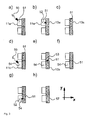
- FIG. 6 shows in the figure parts ai various alternative ways of controlling the surface sequential image acquisition method according to the invention.
- two digital signals (T F ) and (T L ) can be provided, each of which has states (0) and (1) and which control the image acquisition. It can be provided in this case that the signal (T F ) by means of a state change (60), for example from (0) to (1), starts a picture intake and that pulses (61) or state change of the signal (T L ) respectively the start or controls the end of a partial exposure. The number of partial exposures is predetermined and after the last partial exposure, the image sensor is read out.
- the signal (T L ) can also continuously provide a synchronization signal consisting of pulses (63) or state changes, which corresponds in each case to an image feed of one line.
- a synchronization signal consisting of pulses (63) or state changes, which corresponds in each case to an image feed of one line.
- Such signals are often used technically and can be generated for example by rotary encoders or linear encoders, but also by a free-running oscillator.
- a pulse (62) or a state change of the signal (T F ) a multiple exposure according to the invention is started and a predetermined number of partial exposures at times of pulses (63) or state changes of the signal (T L ) are made.
- the signal (T L ) provides a continuous synchronization signal and defined by the duration of a pulse (64) of (T F ), the number of partial exposures at runtime. Also in this case, the partial exposures are triggered by pulses (65) or state change of the signal (T L ).
- a temporal criterion may for example be a time-out, ie the exceeding of a maximum pulse period.
- a digital data channel D can also be provided in order to control the partial exposures.
- a data packet (F) is communicated on the data channel according to an indefinite state (X), which starts the collection of a multiple-exposed image.
- data packets (L) are communicated, each of which triggers a partial exposure. After a predetermined number of lines, the reading of the image and the transfer of the data begins.
- the state of the data channel is irrelevant (X). It can also be provided that the number of partial exposures is transmitted together with the data packet (F) or with one of the data packets (L) or in between.
- a data packet (E) signals the last partial exposure at runtime.
- only one data packet triggers a predetermined number of partial exposures with a predetermined time interval.
- the number or the time interval of the partial exposures can be transmitted together with the data packet (F).
- the data packet (F) can be dispensed with. Then a partial exposure is triggered at each time point (L) and a data packet (E) signals the last partial exposure at runtime.
- i) it may be provided that only data packets (L) trigger a partial exposure.
- the number of partial exposures may be predetermined or at the Luafzeit based on a time criterion, for. B. a time-out can be determined.
- a storage device for. As a register, are provided, which stores the information about the relative movement between the camera and the object.
- FIG. 7 is a schematic diagram showing one and the same column at four consecutive times T1-T4.
- the column itself has image sensor elements R1, R2, R3, R4... Arranged in successive image sensor lines.
- a region of an object line can be partially exposed four times in four successive partial exposures 91, 92, 93, 94, thereby achieving an accumulation of four charges for this region of the object line.
- the correspondingly generated charge is pushed out of the extension 90 of the image sensor region, as a result of which no further partial exposure of the object line region can be performed for this partial exposure.
- the corresponding charge can be removed with a suitable device, such as a so-called fast-dump gate, or it can be read out for further use in the form of a first pre-signal.
- This first pre-signal is less exposed since a partial exposure has been added for this signal.
- the area 97 below the extension area 90 of the image sensor only twice or three times partially exposed object areas are displaced, which are likewise correspondingly less exposed and are either removed or made available as an advance signal.
- a second partial exposure in the uppermost image line R1 in the image sensor region 98 at the upper region of the image sensor is present for which there is no associated first partial exposure, so that for the object line region which is in this second partial exposure at point 98 is detected, a partial exposure is missing and only a total of three partial exposures can be added.
- a single exposure may be provided, i. Also in this area, a reduced exposure of a part of the object is achieved.
- FIG. 8 schematically illustrates a modified image acquisition method according to the invention.
- this image acquisition method three object regions A, B and C are detected by means of the above-described image acquisition method within three image acquisition periods 100, 107, 113 spaced apart from each other.
- Each object area A, B, C has, as shown by way of example by means of the object areas A, B, a fully exposed central area 101 and 108, respectively, and correspondingly less exposed start and end areas 102, 103 and 109, 110.
- the temporally staggered recording of the object areas A, B, C can take place, for example, by subdividing a CCD image area sensor into a plurality of groups of image sensor lines and starting a single image acquisition with these groups, wherein the groups are started at time points offset in time.
- the time intervals between the image-capturing regions 100, 107, 113 are in this case matched with the relative speed between the object and the image sensor in such a way that the less-exposed beginning and end regions of the successively detected object regions completely overlap.
- the end region 103 comes to lie completely overlapping the starting region 109 of the subsequent image-capturing region B, and the less-illuminated end region 110 correspondingly lies completely covering the lower-exposed starting region of the subsequent image region C.
- the three image regions A, B, C can now be joined such that a completely exposed region is formed from the respectively overlapping, less exposed regions, so that only a single less exposed initial region 106 for the object followed by completely exposed Areas 105, 111 (formed from the less exposed areas 103, 109) 112, 114 (again formed of two less exposed areas) and 115 and a correspondingly less exposed end area results.
- the less exposed initial region 106 can continue to be used as a preliminary signal, as explained below.
- FIG. 9 illustrates two alternative ways of arranging a plurality of image sensors or cameras to each other for object detection by means of a plurality of image sensors or cameras.
- such multiple image sensors or cameras may be alternately staggered in the Y-direction and juxtaposed in the X-direction, so that a slight overlap in the X-direction by a few columns or even only one column is possible is and the image sensors or cameras are arranged in a total of two rows.
- an object extending in the X-direction over a large area can then be coherently detected with a high resolution, in that the image sensor areas or cameras perform the image acquisition together in a correspondingly synchronized manner.
- FIG. 9 In the lower arrangement of FIG. 9 Several cameras are shown, which are aligned with each other so that their object detection areas are arranged in a row in the X direction to each other and thereby partially overlap. With this arrangement, in turn, an object extending in the X-direction over a large area can be detected in a detection process, without the need for an alternating staggering in the Y-direction and consequently without a corresponding time synchronization with an offset of the recording times Object line would be required in the corresponding cameras.
- FIG. 10 shows an image capture constellation in which an object moves relative to the image sensor in the row direction.
- the camera can be rotated by 90 °, so that the Y direction of the image sensor corresponds to the X'-relative direction of movement.
- the object moving in this direction can be image-sequentially imaged by the method according to the invention.
- the object in the Y direction extends less far than in the X direction that now a part 143 of the image sensor is used for image capture and a portion 142 of the image sensor remains unused.
- provision can be made not to read out the unused areas of the image sensor, since no relevant image information is present in them
- FIG. 11 schematically shows a diagram in which an automated adjustment of the temporal spacing of the individual partial exposure takes place in order to also sharply image objects that move discontinuously relative to the image sensor or in which the relative movement is not known.
- the synchronization speed (ie the speed at which the transfer and transport processes move the charge across the image sensor area) is continuously varied, as in FIG. 11 symbolized as a solid line.
- a sharpening parameter is determined from the images generated in each case and determined on the basis of predetermined criteria at which synchronization speed the sharpness parameter has assumed the best value. This best synchronization speed value will be used as the basis for the next synchronization speed variation. In this way, a continuous sharpness optimization and tracking of the synchronization speed to the relative speed will take place.
- image quality parameters e.g. As medium brightness, image sharpness parameters, histogram or overdrive areas, signal-to-noise ratio or the like can be used as a criterion for the optimization.
- the optimization can take place here during operation or during a setup or a break in operation.
- the optimization takes place in an adjustment image sensor region and, based on the data determined in this adjustment image sensor region, one or more other regions of the image sensor can actually perform the area sequential object detection in the desired quality which can then be achieved.
- the method according to the invention enables the use of CCD area image sensors for line-sequential image acquisition and such CCD area image sensors usually have a plurality of lines, of which only a few for high-quality object detection by means of the line sequential Procedure needed.
- the exposure causes electrical charges 201-208 in the image sensor elements.
- the object is imaged onto the image sensor elements which receive the electrical charges 204-206, which are shown larger for clarification, whereas the image sensor elements with the charges 201-203, 207 and 208 detect the surrounding area of the object and thus do not receive any information relevant to the further image evaluation ,
- the electrical charges thus generated in the further partial exposure are subsequently in turn transferred in a transfer step into the respective associated shift register elements and in this case cumulated with the charges already present there from the preceding partial exposure.
- This charge state is in Figure 12.2g seen.
- the Charges which result from the exposures of the object are accumulated as charges 225-227, and by the synchronization of the transport processes within the image sensor to the relative movement of the object to the image sensor, partial exposures of a particular object area are combined by the respective transfer step after a partial exposure and the corresponding resulting accumulated electric charges.
- the charges are initially transported from the shift registers by one element down in a transport step, which takes place in a simultaneous, non-contact manner.
- the charge 228, as seen in Figure 12.2f is thereby shifted into an HCCD element and subsequently read out in the course of an entire readout of the HCCD line.
- the cumulative charge 227 resulting from two partial exposures of the object is shifted into the same HCCD element and subsequently read out in the course of an entire readout of the HCCD line. This is in Figure 12.2g shown.
- the charge 226, which is likewise produced from two partial exposures and which likewise represents an object region, is shifted into the same HCCD element and subsequently read out.
Priority Applications (1)
| Application Number | Priority Date | Filing Date | Title |
|---|---|---|---|
| EP08161290A EP2150039A1 (fr) | 2008-07-28 | 2008-07-28 | Procédé de saisie d'image d'objets relativement mobiles |
Applications Claiming Priority (1)
| Application Number | Priority Date | Filing Date | Title |
|---|---|---|---|
| EP08161290A EP2150039A1 (fr) | 2008-07-28 | 2008-07-28 | Procédé de saisie d'image d'objets relativement mobiles |
Publications (1)
| Publication Number | Publication Date |
|---|---|
| EP2150039A1 true EP2150039A1 (fr) | 2010-02-03 |
Family
ID=40291305
Family Applications (1)
| Application Number | Title | Priority Date | Filing Date |
|---|---|---|---|
| EP08161290A Withdrawn EP2150039A1 (fr) | 2008-07-28 | 2008-07-28 | Procédé de saisie d'image d'objets relativement mobiles |
Country Status (1)
| Country | Link |
|---|---|
| EP (1) | EP2150039A1 (fr) |
Cited By (3)
| Publication number | Priority date | Publication date | Assignee | Title |
|---|---|---|---|---|
| CN104541500A (zh) * | 2012-10-12 | 2015-04-22 | 统雷有限公司 | 采用ccd成像仪的时间延迟与积分扫描 |
| DE102014013099A1 (de) | 2014-09-03 | 2016-03-03 | Basler Aktiengesellschaft | Verfahren und Vorrichtung zur vereinfachten Erfassung eines Tiefenbildes |
| WO2019185707A1 (fr) | 2018-03-29 | 2019-10-03 | Thales | Capteur d'images aeroporte realisant des prises de vue matricielle par decalage temporel et sommation multi-spectrales |
Citations (6)
| Publication number | Priority date | Publication date | Assignee | Title |
|---|---|---|---|---|
| US20020060741A1 (en) * | 2000-10-27 | 2002-05-23 | Nikon Corporation | Image capturing apparatus, method for capturing image and camera |
| WO2005057902A2 (fr) * | 2003-12-11 | 2005-06-23 | Advasense Technologies (2004) Ltd | Procede et appareil permettant de compenser les secousses d'une camera |
| JP2005198148A (ja) * | 2004-01-09 | 2005-07-21 | Sony Corp | 固体撮像素子、撮像装置、および固体撮像素子の駆動方法 |
| US20060171694A1 (en) * | 2005-02-01 | 2006-08-03 | Hitachi, Ltd. | Imaging apparatus |
| DE102006051950B3 (de) | 2006-11-01 | 2007-12-13 | Basler Ag | Steuerung für eine elektronische Zeilenkamera |
| DE102007015320A1 (de) | 2006-11-03 | 2008-05-08 | Basler Ag | Verfahren und Vorrichtung zur automatischen Erkennung der relativen Bewegungsrichtung einer Mehrzeilenkamera zum Objekt |
-
2008
- 2008-07-28 EP EP08161290A patent/EP2150039A1/fr not_active Withdrawn
Patent Citations (6)
| Publication number | Priority date | Publication date | Assignee | Title |
|---|---|---|---|---|
| US20020060741A1 (en) * | 2000-10-27 | 2002-05-23 | Nikon Corporation | Image capturing apparatus, method for capturing image and camera |
| WO2005057902A2 (fr) * | 2003-12-11 | 2005-06-23 | Advasense Technologies (2004) Ltd | Procede et appareil permettant de compenser les secousses d'une camera |
| JP2005198148A (ja) * | 2004-01-09 | 2005-07-21 | Sony Corp | 固体撮像素子、撮像装置、および固体撮像素子の駆動方法 |
| US20060171694A1 (en) * | 2005-02-01 | 2006-08-03 | Hitachi, Ltd. | Imaging apparatus |
| DE102006051950B3 (de) | 2006-11-01 | 2007-12-13 | Basler Ag | Steuerung für eine elektronische Zeilenkamera |
| DE102007015320A1 (de) | 2006-11-03 | 2008-05-08 | Basler Ag | Verfahren und Vorrichtung zur automatischen Erkennung der relativen Bewegungsrichtung einer Mehrzeilenkamera zum Objekt |
Cited By (8)
| Publication number | Priority date | Publication date | Assignee | Title |
|---|---|---|---|---|
| CN104541500A (zh) * | 2012-10-12 | 2015-04-22 | 统雷有限公司 | 采用ccd成像仪的时间延迟与积分扫描 |
| EP2907301A4 (fr) * | 2012-10-12 | 2016-08-31 | Thorlabs Inc | Balayage à retard et intégration à l'aide d'un système imageur ccd |
| CN104541500B (zh) * | 2012-10-12 | 2018-11-06 | 统雷有限公司 | 采用ccd成像仪的时间延迟与积分扫描 |
| CN109547714A (zh) * | 2012-10-12 | 2019-03-29 | 统雷有限公司 | 采用ccd成像仪的时间延迟与积分扫描 |
| CN109547714B (zh) * | 2012-10-12 | 2021-03-02 | 统雷有限公司 | 采用ccd成像仪的时间延迟与积分扫描 |
| DE102014013099A1 (de) | 2014-09-03 | 2016-03-03 | Basler Aktiengesellschaft | Verfahren und Vorrichtung zur vereinfachten Erfassung eines Tiefenbildes |
| WO2019185707A1 (fr) | 2018-03-29 | 2019-10-03 | Thales | Capteur d'images aeroporte realisant des prises de vue matricielle par decalage temporel et sommation multi-spectrales |
| FR3079707A1 (fr) * | 2018-03-29 | 2019-10-04 | Thales | Capteur d'images aeroporte realisant des prises de vue matricielle par decalage temporel et sommation multi-spectrales |
Similar Documents
| Publication | Publication Date | Title |
|---|---|---|
| DE69730890T2 (de) | Elektronische Kamera mit einem kleinen Sensor für Hochgeschwindigkeitsbildaufnahme | |
| DE4136461C2 (de) | Vorrichtung und Verfahren zur großflächigen Bildinspektion | |
| CH651408A5 (de) | Optische dokumentenpruefeinrichtung zum erfassen von fehldrucken. | |
| DE102007030985A1 (de) | Bildsensor, Verfahren zum Betreiben eines Bildsensors und Computerprogramm | |
| WO2007031102A1 (fr) | Detection d'un rayonnement optique | |
| DE102019113278B4 (de) | Bildsensoren mit ladungsüberlauffähigkeiten | |
| EP3383026B1 (fr) | Caméra et procédé de détection d'objets se déplaçant vers la caméra dans un dispositif de transport | |
| DE3013282A1 (de) | Detektoranordnung fuer ein optisches system | |
| DE3728750A1 (de) | Vorrichtung zum auslesen eines speicherphosphor-aufzeichnungstraegers | |
| DE60114683T2 (de) | Vorrichtung und Verfahren zum Erzeugen von Taktsignalen | |
| DE102011052874A1 (de) | CMOS-TDI-Sensor zur Anwendung von bildgebenden Röntgenverfahren | |
| CH683893A5 (de) | Verfahren und Kamerasensor zum Abtasten einer Randkante eines Objektes. | |
| DE2504617C3 (de) | Fernsehkamera zur Erzeugung von Signalen von Teilbildern eines Fernsehbildes | |
| EP2150039A1 (fr) | Procédé de saisie d'image d'objets relativement mobiles | |
| DE2801495C3 (de) | Vorrichtung zur Erzeugung eines oder mehrerer Bildsignale, die eine Information über die Bildschärfe eines Bildes oder über die Lagedifferenz zwischen zwei Bildern enthalten | |
| DE102020118999A1 (de) | TDI-Bildsensor mit Fähigkeit zur Belichtungssteuerung und Steuerungssystem mit diesem Sensor | |
| WO2014006147A1 (fr) | Capteur de position optique présentant une mémoire analogique | |
| DE3110828C2 (de) | Verfahren und Anordnung zur Erzeugung von miteinander zu korrelierenden Signalen, insbesondere zur berührungslosen Geschwindigkeitsmessung | |
| DE3636192C1 (de) | Vorrichtung zur Erfassung des Abbildes von Oberflaechenbereichen laufender Warenbahnen | |
| DE10025897B4 (de) | Verfahren zum Betreiben einer optoelektronischen Sensoranordnung und optoelektronische Sensoranordnung | |
| DE102020113183B4 (de) | Kamera und Verfahren zur Erfassung von bewegten Objekten | |
| DE4405865C2 (de) | Verfahren zur Erfassung von Bildinhalten eines zeilenorientierten Bildsensors und zugehörige Einrichtung für Handhabungssysteme | |
| DE102020127495A1 (de) | Aufnahmeverfahren und Aufnahmesystem zum sukzessiven Aufnehmen eines relativ zu einer Kamera bewegten Objekts | |
| DE102020104634A1 (de) | Verfahren zum Auslesen von Bilddaten und zum Erfassen eines Objekts, Bildaufnahmevorrichtung und Lichtscheibenmikroskop | |
| DE102021114204A1 (de) | TDI-Bildsensor mit Fähigkeit zur Einstellung der Belichtungszeit, und Inspektionssystem mit diesem Sensor |
Legal Events
| Date | Code | Title | Description |
|---|---|---|---|
| PUAI | Public reference made under article 153(3) epc to a published international application that has entered the european phase |
Free format text: ORIGINAL CODE: 0009012 |
|
| AK | Designated contracting states |
Kind code of ref document: A1 Designated state(s): AT BE BG CH CY CZ DE DK EE ES FI FR GB GR HR HU IE IS IT LI LT LU LV MC MT NL NO PL PT RO SE SI SK TR |
|
| AX | Request for extension of the european patent |
Extension state: AL BA MK RS |
|
| 17P | Request for examination filed |
Effective date: 20100803 |
|
| 17Q | First examination report despatched |
Effective date: 20100903 |
|
| AKX | Designation fees paid |
Designated state(s): AT BE BG CH CY CZ DE DK EE ES FI FR GB GR HR HU IE IS IT LI LT LU LV MC MT NL NO PL PT RO SE SI SK TR |
|
| STAA | Information on the status of an ep patent application or granted ep patent |
Free format text: STATUS: THE APPLICATION IS DEEMED TO BE WITHDRAWN |
|
| 18D | Application deemed to be withdrawn |
Effective date: 20130309 |