EP2149926A1 - Akkumulator - Google Patents
Akkumulator Download PDFInfo
- Publication number
- EP2149926A1 EP2149926A1 EP20090164456 EP09164456A EP2149926A1 EP 2149926 A1 EP2149926 A1 EP 2149926A1 EP 20090164456 EP20090164456 EP 20090164456 EP 09164456 A EP09164456 A EP 09164456A EP 2149926 A1 EP2149926 A1 EP 2149926A1
- Authority
- EP
- European Patent Office
- Prior art keywords
- accumulator
- cells
- cell
- wall
- sheath
- Prior art date
- Legal status (The legal status is an assumption and is not a legal conclusion. Google has not performed a legal analysis and makes no representation as to the accuracy of the status listed.)
- Granted
Links
Images
Classifications
-
- H—ELECTRICITY
- H01—ELECTRIC ELEMENTS
- H01M—PROCESSES OR MEANS, e.g. BATTERIES, FOR THE DIRECT CONVERSION OF CHEMICAL ENERGY INTO ELECTRICAL ENERGY
- H01M10/00—Secondary cells; Manufacture thereof
- H01M10/60—Heating or cooling; Temperature control
- H01M10/61—Types of temperature control
- H01M10/613—Cooling or keeping cold
-
- H—ELECTRICITY
- H01—ELECTRIC ELEMENTS
- H01M—PROCESSES OR MEANS, e.g. BATTERIES, FOR THE DIRECT CONVERSION OF CHEMICAL ENERGY INTO ELECTRICAL ENERGY
- H01M10/00—Secondary cells; Manufacture thereof
- H01M10/60—Heating or cooling; Temperature control
- H01M10/61—Types of temperature control
- H01M10/617—Types of temperature control for achieving uniformity or desired distribution of temperature
-
- H—ELECTRICITY
- H01—ELECTRIC ELEMENTS
- H01M—PROCESSES OR MEANS, e.g. BATTERIES, FOR THE DIRECT CONVERSION OF CHEMICAL ENERGY INTO ELECTRICAL ENERGY
- H01M10/00—Secondary cells; Manufacture thereof
- H01M10/60—Heating or cooling; Temperature control
- H01M10/65—Means for temperature control structurally associated with the cells
- H01M10/653—Means for temperature control structurally associated with the cells characterised by electrically insulating or thermally conductive materials
-
- H—ELECTRICITY
- H01—ELECTRIC ELEMENTS
- H01M—PROCESSES OR MEANS, e.g. BATTERIES, FOR THE DIRECT CONVERSION OF CHEMICAL ENERGY INTO ELECTRICAL ENERGY
- H01M10/00—Secondary cells; Manufacture thereof
- H01M10/60—Heating or cooling; Temperature control
- H01M10/65—Means for temperature control structurally associated with the cells
- H01M10/655—Solid structures for heat exchange or heat conduction
- H01M10/6554—Rods or plates
-
- H—ELECTRICITY
- H01—ELECTRIC ELEMENTS
- H01M—PROCESSES OR MEANS, e.g. BATTERIES, FOR THE DIRECT CONVERSION OF CHEMICAL ENERGY INTO ELECTRICAL ENERGY
- H01M10/00—Secondary cells; Manufacture thereof
- H01M10/60—Heating or cooling; Temperature control
- H01M10/65—Means for temperature control structurally associated with the cells
- H01M10/655—Solid structures for heat exchange or heat conduction
- H01M10/6554—Rods or plates
- H01M10/6555—Rods or plates arranged between the cells
-
- H—ELECTRICITY
- H01—ELECTRIC ELEMENTS
- H01M—PROCESSES OR MEANS, e.g. BATTERIES, FOR THE DIRECT CONVERSION OF CHEMICAL ENERGY INTO ELECTRICAL ENERGY
- H01M50/00—Constructional details or processes of manufacture of the non-active parts of electrochemical cells other than fuel cells, e.g. hybrid cells
- H01M50/20—Mountings; Secondary casings or frames; Racks, modules or packs; Suspension devices; Shock absorbers; Transport or carrying devices; Holders
- H01M50/233—Mountings; Secondary casings or frames; Racks, modules or packs; Suspension devices; Shock absorbers; Transport or carrying devices; Holders characterised by physical properties of casings or racks, e.g. dimensions
- H01M50/24—Mountings; Secondary casings or frames; Racks, modules or packs; Suspension devices; Shock absorbers; Transport or carrying devices; Holders characterised by physical properties of casings or racks, e.g. dimensions adapted for protecting batteries from their environment, e.g. from corrosion
-
- H—ELECTRICITY
- H01—ELECTRIC ELEMENTS
- H01M—PROCESSES OR MEANS, e.g. BATTERIES, FOR THE DIRECT CONVERSION OF CHEMICAL ENERGY INTO ELECTRICAL ENERGY
- H01M10/00—Secondary cells; Manufacture thereof
- H01M10/60—Heating or cooling; Temperature control
- H01M10/65—Means for temperature control structurally associated with the cells
- H01M10/651—Means for temperature control structurally associated with the cells characterised by parameters specified by a numeric value or mathematical formula, e.g. ratios, sizes or concentrations
-
- Y—GENERAL TAGGING OF NEW TECHNOLOGICAL DEVELOPMENTS; GENERAL TAGGING OF CROSS-SECTIONAL TECHNOLOGIES SPANNING OVER SEVERAL SECTIONS OF THE IPC; TECHNICAL SUBJECTS COVERED BY FORMER USPC CROSS-REFERENCE ART COLLECTIONS [XRACs] AND DIGESTS
- Y02—TECHNOLOGIES OR APPLICATIONS FOR MITIGATION OR ADAPTATION AGAINST CLIMATE CHANGE
- Y02E—REDUCTION OF GREENHOUSE GAS [GHG] EMISSIONS, RELATED TO ENERGY GENERATION, TRANSMISSION OR DISTRIBUTION
- Y02E60/00—Enabling technologies; Technologies with a potential or indirect contribution to GHG emissions mitigation
- Y02E60/10—Energy storage using batteries
-
- Y—GENERAL TAGGING OF NEW TECHNOLOGICAL DEVELOPMENTS; GENERAL TAGGING OF CROSS-SECTIONAL TECHNOLOGIES SPANNING OVER SEVERAL SECTIONS OF THE IPC; TECHNICAL SUBJECTS COVERED BY FORMER USPC CROSS-REFERENCE ART COLLECTIONS [XRACs] AND DIGESTS
- Y10—TECHNICAL SUBJECTS COVERED BY FORMER USPC
- Y10T—TECHNICAL SUBJECTS COVERED BY FORMER US CLASSIFICATION
- Y10T29/00—Metal working
- Y10T29/49—Method of mechanical manufacture
- Y10T29/49002—Electrical device making
- Y10T29/49108—Electric battery cell making
-
- Y—GENERAL TAGGING OF NEW TECHNOLOGICAL DEVELOPMENTS; GENERAL TAGGING OF CROSS-SECTIONAL TECHNOLOGIES SPANNING OVER SEVERAL SECTIONS OF THE IPC; TECHNICAL SUBJECTS COVERED BY FORMER USPC CROSS-REFERENCE ART COLLECTIONS [XRACs] AND DIGESTS
- Y10—TECHNICAL SUBJECTS COVERED BY FORMER USPC
- Y10T—TECHNICAL SUBJECTS COVERED BY FORMER US CLASSIFICATION
- Y10T29/00—Metal working
- Y10T29/49—Method of mechanical manufacture
- Y10T29/49002—Electrical device making
- Y10T29/49108—Electric battery cell making
- Y10T29/49115—Electric battery cell making including coating or impregnating
Definitions
- the present invention relates to an accumulator having a plurality of accumulator cells, which are arranged spaced apart in an accumulator housing, which is at least partially filled with a filling material enclosing the accumulator cells.
- Such accumulators consist of individual accumulator cells connected together to form packs or modules and are therefore often referred to as battery packs or accumulator modules.
- the individual accumulator cells are usually arranged in a symmetrical arrangement in a generally filled with plastic accumulator housing.
- the plastic encases the battery cells, which generate heat due to heating in charging and discharging by the currents flowing in this case, which can affect the functioning of the batteries. This heat is dissipated via the plastic sheaths from the interior of the accumulator to the environment in order to prevent excessive heating of the battery cells and thus of the accumulator.
- a disadvantage of the prior art is that around the center of the accumulator housing arranged around accumulator cells, or accumulator cells with a larger number of adjacent cells usually heat up due to poorer heat dissipation more than the cells at the edge of the housing or as cells with less neighboring cells. This results in an inhomogeneous temperature distribution in the accumulator housing, wherein the more heated accumulator cells age faster or faster than the less heated cells. This leads to an early aging of the more heated with increasing number of charge and discharge cycles Accumulator cells up to a time at which is prematurely unusable due to a defect of one of these cells of the accumulator and thus the life of the accumulator is shortened.
- the individual battery cells also heat each other in loading and unloading. This can lead to a local overheating of the accumulator, which can impair the safety during its use, especially in the case of accumulator cells with a comparatively large number of directly adjacent accumulator cells.
- An object of the invention is therefore to provide a new accumulator, or battery pack or battery module, with improved thermal management, in which an extension of the service life and an improvement in safety during operation is made possible.
- an accumulator having a plurality of accumulator cells, which are arranged at a distance from one another in an accumulator housing which is at least partially filled with a filling material covering the accumulator cells.
- a first battery cell has a first casing and a second battery cell has a second casing, the first casing and the second casing having different wall thicknesses at least in sections.
- the invention thus makes it possible to reduce the heating of selected accumulator cells in the operation of the accumulator by directly adjacent accumulator cells by increasing the wall thickness to these neighboring cells and to improve the heat dissipation of these cells.
- the first and second sheath are designed to effect a substantially homogeneous temperature distribution in the interior of the accumulator housing during operation of the accumulator.
- the first sheath has a greater wall thickness in the region between the first accumulator cell and at least part of its immediately adjacent accumulator cells than the second sheath in the region between the second accumulator cell and its immediately adjacent accumulator cells.
- accumulator cells having comparatively many immediately adjacent accumulator cells can be spaced a greater distance from their immediately adjacent accumulator cells than accumulator cells having comparatively few immediately adjacent accumulator cells, so that a more homogeneous temperature distribution in the accumulator can be achieved.
- the accumulator housing has a housing outer wall and the second accumulator cell is arranged in the region of the housing outer wall, the second sheath has a bead-like widening in the region between the second accumulator cell and the housing outer wall.
- the first sheath in the region between the first accumulator cell and the housing outer wall has a smaller wall thickness than the bead-like enlargement.
- the heat generated by the first accumulator cell can thus be discharged via the housing outer wall faster to the environment than the heat generated by the second accumulator cell.
- the accumulator housing has a housing outer wall and the first and second accumulator cell are arranged in the region of the housing outer wall, the first accumulator cell has more immediately adjacent accumulator cells, as the second accumulator cell, the second sheath in the region between the second accumulator cell and the housing outer wall on a bead-like extension, and the first sheath has in the area between the first accumulator cell and the housing outer wall has a smaller wall thickness, as the bead-like extension.
- the invention thus also makes it possible, even in the case of an accumulator in which the accumulator cells have substantially identical spacings to adjacent accumulator cells, to improve thermal management, in which the heat generated by the accumulator cells with comparatively many immediately adjacent accumulator cells can be dissipated more rapidly via the housing outer wall to the environment , as the heat generated by the accumulator cells with comparatively few immediately adjacent accumulator cells.
- thermal management in which the heat generated by the accumulator cells with comparatively many immediately adjacent accumulator cells can be dissipated more rapidly via the housing outer wall to the environment , as the heat generated by the accumulator cells with comparatively few immediately adjacent accumulator cells.
- Plastic is preferably used as filling material.
- a power tool having an accumulator which has a plurality of accumulator cells which are arranged at a distance from one another in an accumulator housing which is at least partially filled with a filling material covering the accumulator cells.
- a first accumulator cell has a first sheath and a second accumulator cell has a second sheath. The first sheath and the second sheath have at least sections of different wall thicknesses.
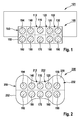
- Fig. 1 shows a preferably suitable for powering a power tool machine 101 shown schematically suitable accumulator 100 with a plurality of battery cells 110, 120, 130, 140, 160, 170, 180, 190, 192, 194, which are arranged in a battery housing 150 and a pack or module are switched together.
- the accumulator cells 110, 120, 130, 140, 160, 170, 180, 190, 192, 194 may be of any type of accumulator, such as NiCd, NiMh, and Li-lon.
- the use of the battery 100 for powering the power tool 101 is described by way of example only, but the use of the battery 100 is not limited thereto. Rather, the accumulator 100 can be used in many different devices, for example in a stationary energy storage or energy storage in vehicles. Such and other modifications and variations are possible within the scope of the present invention.
- the accumulator housing 150 has a housing outer wall 152 and is internally at least partially filled with a filling material, e.g. with plastic.
- This filling material encases the battery cells 110, 120, 130, 140, 160, 170, 180, 190, 192, 194 at least in sections, preferably completely, with the exception of the end faces.
- the accumulator cell 110 has a shroud 112 shown in dashed lines
- the accumulator cell 120 has a sheath 122 shown in dashed lines
- the accumulator cell 130 has a sheath 132 shown in dashed lines.
- the housings are usually filled or filled with plastic by plastic spraying.
- plastic sheath encompasses not only a sheath directly provided on an accumulator cell, but also a portion of such an integral plastic block or filling material which directly surrounds and is thus assigned to an accumulator cell. can be assigned visually, as well as partitions between accumulator cells in the broadest sense.
- At least two of the sheaths of the battery cells 110, 120, 130, 140, 160, 170, 180, 190, 192, 194 have at least sections of different wall thicknesses.
- the sheaths 112 and 132 have different wall thicknesses. These different wall thicknesses are preferably predetermined such that, during operation of the accumulator 100, a substantially homogeneous temperature distribution in the interior of the accumulator housing 150 is achieved.
- accumulator cells 110, 120, 130, 140, 160, 170, 180, 190, 192, 194 are arranged in the region of the housing outer wall 152 and surrounded inside the housing by immediately adjacent accumulator cells.
- the accumulator cell 110 has five immediately adjacent accumulator cells, namely the cells 120, 140, 160, 170 and 180.
- the accumulator cell 130 has only three immediately adjacent accumulator cells, namely the cells 120, 160 and 190.
- the sheath 112 at least in the region between the accumulator cell 110 and its immediately adjacent accumulator cells 120, 140, 160, 170, 180 has a greater wall thickness than the sheath 132 in the region between the accumulator cell 130 and its immediately adjacent accumulator cells 120, 160, 190.
- This larger wall thickness reduces heating of the battery cell 110 by the neighboring cells 120, 140, 160, 170, 180.
- Fig. 1 can be seen in the accumulator 100 all accumulator cells 110, 120, 130, 140, 160, 170, 180, 190, 192, 194 exemplified identical distances to the housing outer wall 152, or their shells have substantially matching wall thicknesses in the edge region of the accumulator housing 150th
- the outer accumulator cells 130, 190, 192, 194 cool faster since they have fewer immediately adjacent cells and a larger lateral surface facing the outer wall 152 of the housing ,
- Fig. 2 shows a preferably for powering a power tool, such as the power tool 101 of Fig. 1 , suitable accumulator 200 according to another embodiment, which is a modification of the accumulator 100 of Fig. 1 represents.
- the accumulator housing 250 is like the accumulator housing 150 of Fig.
- the battery cell 110 has a shroud 212 shown in dashed lines
- the accumulator cell 120 a shroud 222 shown in dashed lines
- the accumulator cell 130 has a sheath 232 shown in dashed lines.
- sheaths can as in Fig. 1 be formed described, or alternatively, at least in the areas between the battery cells 110, 120, 130, 140, 160, 170, 180, 190, 192, 194 have approximately matching wall thicknesses.
- the jacket 232 of the accumulator cell 130 arranged in the region of the housing outer wall 252 has a bead-like extension 230, which is preferably provided in the region between the accumulator cell 130 and the housing outer wall 252.
- the accumulator cells 190, 192, 194 may have similar bead-like extensions as in FIG Fig. 2 shown.
- the term "bead-like extension" means a voluminous formation or bulge.
- the bead-like extension 230 is designed to prevent over-cooling of the accumulator cell 130 during operation of the accumulator 200.
- the accumulator cell 130 remains warmer, so that a more homogeneous temperature distribution in the accumulator 200 can be achieved.
- the accumulator cells 110, 170 arranged inside the housing do not age disproportionately fast in comparison to the outer accumulator cells 130, 190, 192, 194 and the service life of the individual accumulator cells 110, 120, 130, 140, 160, 170, 180, 190, 192, 194 is adapted to each other.
- the casing of the accumulator cells 110, 170, eg the sheathing 212, which is arranged inside the housing, have a smaller wall thickness in the area between the assigned accumulator cell 110 and the housing outer wall 252 than the bead-like extensions, eg the extension 230.
- the cells 110, 170 generated heat can therefore better and faster to the Be derived environment, so that an approximation of the temperatures of the inner and outer battery cells and thus a more homogeneous temperature distribution can be achieved.
- the homogenization of the temperature distribution can be further improved if the distances between the individual battery cells 110, 120, 130, 140, 160, 170, 180, 190, 192, 194 or the wall thicknesses of their shells in the region between the individual cells as in Fig. 1 be described described. As a result, the life of the battery 200 can be prolonged.
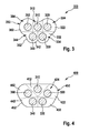
- Fig. 3 shows a preferably for powering a power tool, such as the power tool 101 of Fig. 1 , suitable accumulator 300 according to another embodiment, with separate battery cells 310, 320, 330, 340, 360, which are connected together in a battery housing 350 with a housing outer wall 352 to form a pack or module.
- These have associated sheaths 312, 322, 332, 342, 362 similar to those of FIG Fig. 1 and 2 described by filling the housing 350 with plastic.
- the sheaths 322, 332, 342, 362 have bead-like extensions 324, 334, 344, 364.
- the sheath 312 has the housing outer wall 352 out only a small wall thickness.
- the accumulator cells 330, 340 each have three neighboring cells, namely the cells 310, 320, 340 and 310, 330, 360. Therefore, their sheaths 332, 342 have towards the housing outer wall 352 toward bead-like extensions 334, 344 with a wall thickness, preferably larger is the corresponding wall thickness of the sheath 312.
- the battery cells 320, 360 each have only two neighboring cells, namely the cells 310, 330 and 310, 340. Therefore, their sheaths 322, 322 have 362 to the housing outer wall 352 out bead-like extensions 324, 364 with a wall thickness which is preferably greater than the corresponding wall thickness of the bead-like extensions 334, 344 and thus the largest wall thickness in the accumulator 300th
- Fig. 4 shows a preferably for powering a power tool, such as the power tool 101 of Fig. 1
- a suitable accumulator 400 according to another embodiment, which is a modification of the accumulator 300 of Fig. 3 represents.
- the shells 310, 320, 330, 340, 360 have sheaths 412, 422, 432, 442, 462 associated with the shells 312, 322, 332, 342, 362 of FIG Fig. 3 as beadlike extensions can have.
- the sheath 422 has a bead-like extension 424.
- the accumulator cell 310 in the accumulator 400 in FIG Fig. 4 shifted upward, so as to reduce a heating of the cell 310 by the battery cells 330, 340 during operation of the accumulator 400. Conversely, unwanted heating of the cells 330, 340 by the accumulator cell 310 during operation of the accumulator 400 is prevented.
- a substantially homogeneous temperature distribution in the accumulator 400 can be achieved, so that a longer life and improved safety in use can be achieved.
Landscapes
- Chemical & Material Sciences (AREA)
- Chemical Kinetics & Catalysis (AREA)
- Electrochemistry (AREA)
- General Chemical & Material Sciences (AREA)
- Engineering & Computer Science (AREA)
- Manufacturing & Machinery (AREA)
- Battery Mounting, Suspending (AREA)
- Secondary Cells (AREA)
Abstract
Description
- Die vorliegende Erfindung betrifft einen Akkumulator mit einer Mehrzahl von Akkumulatorzellen, die voneinander beabstandet in einem Akkumulatorgehäuse angeordnet sind, das zumindest teilweise mit einem die Akkumulatorzellen ummantelnden Füllmaterial gefüllt ist.
- Derartige Akkumulatoren bestehen aus einzelnen, zu Packs oder Modulen zusammen geschalteten Akkumulatorzellen und werden deshalb häufig auch als Akkupacks oder Akku-Module bezeichnet. In diesen Akkumulatoren bzw. Akkupacks oder Akku-Modulen sind die einzelnen Akkumulatorzellen meist in einer symmetrischen Anordnung in einem in der Regel mit Kunststoff gefüllten Akkumulatorgehäuse angeordnet. Der Kunststoff ummantelt die Akkumulatorzellen, die aufgrund einer Erhitzung im Lade- und Entladebetrieb durch die hierbei fließenden Ströme Wärme erzeugen, die die Funktionsfähigkeit der Akkumulatoren beeinträchtigen kann. Diese Wärme wird über die Kunststoff-Ummantelungen aus dem Inneren des Akkumulators an die Umgebung abgeleitet, um eine zu starke Erhitzung der Akkumulatorzellen und somit des Akkumulators zu verhindern.
- Nachteilig am Stand der Technik ist, dass die um den Mittelpunkt des Akkumulatorgehäuses herum angeordneten Akkumulatorzellen, bzw. Akkumulatorzellen mit einer größeren Anzahl benachbarter Zellen, sich aufgrund einer schlechteren Wärmeableitung meist stärker erhitzen, als die Zellen am Rand des Gehäuses bzw. als Zellen mit weniger benachbarten Zellen. Hieraus ergibt sich eine inhomogene Temperaturverteilung im Akkumulatorgehäuse, wobei die stärker erhitzten Akkumulatorzellen stärker bzw. schneller altern als die weniger erhitzten Zellen. Dies führt mit zunehmender Anzahl von Lade- und Entladezyklen zu einer frühzeitigen Alterung der stärker erhitzten Akkumulatorzellen bis zu einem Zeitpunkt, an dem durch einen Defekt einer dieser Zellen der Akkumulator vorzeitig unbrauchbar wird und somit die Lebensdauer des Akkumulators verkürzt wird. Darüber hinaus heizen sich die einzelnen Akkumulatorzellen im Lade- und Entladebetrieb auch gegenseitig auf. Dies kann insbesondere bei Akkumulatorzellen mit einer vergleichsweise großen Anzahl von unmittelbar benachbarten Akkumulatorzellen zu einer lokalen Überhitzung des Akkumulators führen, die die Sicherheit bei dessen Benutzung beeinträchtigen kann.
- Eine Aufgabe der Erfindung ist es daher, einen neuen Akkumulator, bzw. Akkupack oder Akku-Modul, mit verbessertem Thermomanagement bereit zu stellen, bei dem eine Verlängerung der Lebensdauer und eine Verbesserung der Sicherheit im Betrieb ermöglicht wird.
- Dieses Problem wird gelöst durch einen Akkumulator mit einer Mehrzahl von Akkumulatorzellen, die voneinander beabstandet in einem Akkumulatorgehäuse angeordnet sind, das zumindest teilweise mit einem die Akkumulatorzellen ummantelnden Füllmaterial gefüllt ist. Eine erste Akkumulatorzelle hat eine erste Ummantelung und eine zweite Akkumulatorzelle eine zweite Ummantelung, wobei die erste Ummantelung und die zweite Ummantelung zumindest abschnittsweise unterschiedliche Wandstärken aufweisen.
- Die Erfindung ermöglicht somit, ein Aufheizen von ausgewählten Akkumulatorzellen im Betrieb des Akkumulators durch unmittelbar benachbarte Akkumulatorzellen durch eine Vergrößerung der Wandstärke zu diesen Nachbarzellen zu reduzieren und die Wärmeableitung von diesen Zellen verbessern.
- Gemäß einer Ausführungsform sind die erste und zweite Ummantelung dazu ausgebildet, im Betrieb des Akkumulators eine im Wesentlichen homogene Temperaturverteilung im Inneren des Akkumulatorgehäuses zu bewirken.
- Somit kann im Betrieb des Akkumulators ein verbessertes Thermomanagement erzielt werden, sodass die Lebensdauer des Akkumulators verlängert und die Gebrauchssicherheit vergrößert werden.
- Gemäß einer Ausführungsform, bei der die erste Akkumulatorzelle mehr unmittelbar benachbarte Akkumulatorzellen hat, als die zweite Akkumulatorzelle, weist die erste Ummantelung im Bereich zwischen der ersten Akkumulatorzelle und zumindest einem Teil ihrer unmittelbar benachbarten Akkumulatorzellen eine größere Wandstärke auf, als die zweite Ummantelung im Bereich zwischen der zweiten Akkumulatorzelle und ihren unmittelbar benachbarten Akkumulatorzellen.
- Somit können Akkumulatorzellen, die vergleichsweise viele unmittelbar benachbarte Akkumulatorzellen haben, mit einem größeren Abstand von ihren unmittelbar benachbarten Akkumulatorzellen beabstandet werden, als Akkumulatorzellen mit vergleichsweise wenigen unmittelbar benachbarten Akkumulatorzellen, sodass eine homogenere Temperaturverteilung im Akkumulator erzielt werden kann.
- Falls bei dieser Ausführungsform das Akkumulatorgehäuse eine Gehäuseaußenwand aufweist und die zweite Akkumulatorzelle im Bereich der Gehäuseaußenwand angeordnet ist, weist die zweite Ummantelung im Bereich zwischen der zweiten Akkumulatorzelle und der Gehäuseaußenwand eine wulstartige Erweiterung auf.
- Somit kann eine zu starke Abkühlung der zweiten Akkumulatorzelle im Betrieb des Akkumulators verhindert werden.
- Falls die erste Akkumulatorzelle ebenfalls im Bereich der Gehäuseaußenwand angeordnet ist, weist die erste Ummantelung im Bereich zwischen der ersten Akkumulatorzelle und der Gehäuseaußenwand eine geringere Wandstärke auf, als die wulstartige Erweiterung.
- Die von der ersten Akkumulatorzelle erzeugte Wärme kann somit über die Gehäuseaußenwand schneller an die Umgebung abgeleitet werden, als die von der zweiten Akkumulatorzelle erzeugte Wärme.
- Gemäß einer Ausführungsform, bei der das Akkumulatorgehäuse eine Gehäuseaußenwand aufweist und die erste und zweite Akkumulatorzelle im Bereich der Gehäuseaußenwand angeordnet sind, wobei die erste Akkumulatorzelle mehr unmittelbar benachbarte Akkumulatorzellen aufweist, als die zweite Akkumulatorzelle, weist die zweite Ummantelung im Bereich zwischen der zweiten Akkumulatorzelle und der Gehäuseaußenwand eine wulstartige Erweiterung auf, und die erste Ummantelung weist im Bereich zwischen der ersten Akkumulatorzelle und der Gehäuseaußenwand eine geringere Wandstärke auf, als die wulstartige Erweiterung.
- Die Erfindung ermöglicht somit auch bei einem Akkumulator, bei dem die Akkumulatorzellen im Wesentlichen identische Abstände zu benachbarten Akkumulatorzellen aufweisen, ein verbessertes Thermomanagement, bei dem die von den Akkumulatorzellen mit vergleichsweise vielen unmittelbar benachbarten Akkumulatorzellen erzeugte Wärme über die Gehäuseaußenwand schneller an die Umgebung abgeleitet werden kann, als die von den Akkumulatorzellen mit vergleichsweise wenigen unmittelbar benachbarten Akkumulatorzellen erzeugte Wärme. Somit kann auch bei diesem Akkumulator eine homogenere Temperaturverteilung erzielt werden.
- Als Füllmaterial wird bevorzugt Kunststoff verwendet.
- Das Eingangs genannte Problem wird auch gelöst durch eine Elektrowerkzeugmaschine mit einem Akkumulator, der eine Mehrzahl von Akkumulatorzellen aufweist, die voneinander beabstandet in einem Akkumulatorgehäuse angeordnet sind, das zumindest teilweise mit einem die Akkumulatorzellen ummantelnden Füllmaterial gefüllt ist. Eine erste Akkumulatorzelle weist eine erste Ummantelung auf und eine zweite Akkumulatorzelle eine zweite Ummantelung. Die erste Ummantelung und die zweite Ummantelung weisen zumindest abschnittsweise unterschiedliche Wandstärken auf.
- Die Erfindung ist anhand eines in den Zeichnungen dargestellten Ausführungsbeispiels in der nachfolgenden Beschreibung näher erläutert. Es zeigen:
- Fig. 1
- eine erste Ausführungsform eines Akkumulators gemäß der Erfindung,
- Fig. 2
- eine zweite Ausführungsform eines Akkumulators gemäß der Erfindung,
- Fig. 3 und
- eine dritte Ausführungsform eines Akkumulators gemäß der Erfindung,
- Fig. 4
- eine vierte Ausführungsform eines Akkumulators gemäß der Erfindung.
-
Fig. 1 zeigt einen vorzugsweise zur Stromversorgung einer schematisch dargestellten Elektrowerkzeugmaschine 101 geeigneten Akkumulator 100 mit einer Mehrzahl von Akkumulatorzellen 110, 120, 130, 140, 160, 170, 180, 190, 192, 194, die in einem Akkumulatorgehäuse 150 angeordnet und zu einem Pack oder Modul zusammen geschaltet sind. Die Akkumulatorzellen 110, 120, 130, 140, 160, 170, 180, 190, 192, 194 können von einem beliebigen Akkumulatortyp sein, wie z.B. NiCd, NiMh und Li-lon. - Es wird jedoch darauf hingewiesen, dass die Verwendung des Akkumulators 100 zur Stromversorgung der Elektrowerkzeugmaschine 101 lediglich beispielhaft beschrieben ist, die Verwendung des Akkumulators 100 jedoch nicht hierauf beschränkt ist. Vielmehr kann der Akkumulator 100 in vielen unterschiedlichen Vorrichtungen Anwendung finden, z.B. in einem stationären Energiespeicher oder einem Energiespeicher in Fahrzeugen. Derartige und weitere Modifikationen und Variationen sind im Rahmen der vorliegenden Erfindung möglich.
- Das Akkumulatorgehäuse 150 hat eine Gehäuseaußenwand 152 und ist in seinem Inneren mindestens teilweise mit einem Füllmaterial gefüllt, z.B. mit Kunststoff. Dieses Füllmaterial ummantelt die Akkumulatorzellen 110, 120, 130, 140, 160, 170, 180, 190, 192, 194 zumindest abschnittsweise, bevorzugt vollständig mit Ausnahme der Stirnflächen. Beispielsweise hat die Akkumulatorzelle 110 eine gestrichelt dargestellte Ummantelung 112, die Akkumulatorzelle 120 eine gestrichelt dargestellte Ummantelung 122 und die Akkumulatorzelle 130 eine gestrichelt dargestellte Ummantelung 132.
- Es wird darauf hingewiesen, dass bei gebräuchlichen Herstellungsverfahren von Akkumulatoren, bei denen Akkumulatorzellen in einem Akkumulatorgehäuse von Kunststoff umgeben sind, die Gehäuse in der Regel durch Kunststoffspritzen mit dem Kunststoff gefüllt bzw. ausgegossen werden. Somit ist nicht jede Akkumulatorzelle separat von einer Kunststoff-Ummantelung umschlossen, sondern vielmehr sind alle Akkumulatorzellen in einen einstückigen Kunststoffblock eingebettet. Deshalb umfasst der Begriff "Ummantelung" im Kontext der vorliegenden Erfindung nicht nur eine an einer Akkumulatorzelle unmittelbar vorgesehene bzw. angebrachte Hülle, sondern auch einen Abschnitt eines derartigen einstückigen Kunststoffblocks bzw. des Füllmaterials, das eine Akkumulatorzelle unmittelbar umgibt und dieser somit zugeordnet wird bzw. visuell zugeordnet werden kann, sowie Trennwände zwischen Akkumulatorzellen im weitesten Sinne.
- Gemäß einer Ausführungsform der Erfindung haben wenigstens zwei der Ummantelungen der Akkumulatorzellen 110, 120, 130, 140, 160, 170, 180, 190, 192, 194 zumindest abschnittsweise unterschiedliche Wandstärken. Wie aus
Fig. 1 ersichtlich, haben z.B. die Ummantelungen 112 und 132 verschiedene Wandstärken. Diese unterschiedlichen Wandstärken sind bevorzugt derart vorgegeben, dass im Betrieb des Akkumulators 100 eine im Wesentlichen homogene Temperaturverteilung im Inneren des Akkumulatorgehäuses 150 erzielt wird. - In
Fig. 1 sind alle Akkumulatorzellen 110, 120, 130, 140, 160, 170, 180, 190, 192, 194 im Bereich der Gehäuseaußenwand 152 angeordnet und im Gehäuseinneren von unmittelbar benachbarten Akkumulatorzellen umgeben. - Z.B. hat die Akkumulatorzelle 110 fünf unmittelbar benachbarte Akkumulatorzellen, und zwar die Zellen 120, 140, 160, 170 und 180. Die Akkumulatorzelle 130 hat dahingegen nur drei unmittelbar benachbarte Akkumulatorzellen, und zwar die Zellen 120, 160 und 190.
- Da Akkumulatorzellen auch von benachbarten Akkumulatorzellen aufgeheizt werden, ist davon auszugehen, dass z.B. die Akkumulatorzelle 110 sich im Betrieb des Akkumulators 100 stärker erhitzt als die Akkumulatorzelle 130, die zwei Nachbarzellen weniger hat. Deshalb weist die Ummantelung 112 zumindest im Bereich zwischen der Akkumulatorzelle 110 und deren unmittelbar benachbarten Akkumulatorzellen 120, 140, 160, 170, 180 eine größere Wandstärke auf, als die Ummantelung 132 im Bereich zwischen der Akkumulatorzelle 130 und deren unmittelbar benachbarten Akkumulatorzellen 120, 160, 190. Diese größere Wandstärke reduziert ein Aufheizen der Akkumulatorzelle 110 durch die Nachbarzellen 120, 140, 160, 170, 180. Somit wird die im Betrieb des Akkumulators 100 maximal mögliche Temperatur der Akkumulatorzelle 110 reduziert, wodurch eine zu schnelle Alterung der Zelle 110 verhindert und eine lokale Überhitzung vermieden werden kann.
- Wie aus
Fig. 1 ersichtlich, haben bei dem Akkumulator 100 alle Akkumulatorzellen 110, 120, 130, 140, 160, 170, 180, 190, 192, 194 beispielhaft identische Abstände zur Gehäuseaußenwand 152, bzw. deren Ummantelungen haben im Wesentlichen übereinstimmende Wandstärken im Randbereich des Akkumulatorgehäuses 150. Obwohl eine zu starke Erwärmung insbesondere der inneren Akkumulatorenzellen 110, 170 durch die oben beschriebenen Maßnahmen vermieden wird, kühlen die äußeren Akkumulatorenzellen 130, 190, 192, 194 schneller ab, da sie weniger unmittelbar benachbarte Zellen und eine größere, der Gehäuseaußenwand 152 zugewandte Mantelfläche aufweisen. -
Fig. 2 zeigt einen vorzugsweise zur Stromversorgung einer Elektrowerkzeugmaschine, z.B. der Elektrowerkzeugmaschine 101 vonFig. 1 , geeigneten Akkumulator 200 gemäß einer weiteren Ausführungsform, der eine Abwandlung des Akkumulators 100 vonFig. 1 repräsentiert. Bei dem Akkumulator 200 sind die Akkumulatorzellen 110, 120, 130, 140, 160, 170, 180, 190, 192, 194 in einem Akkumulatorgehäuse 250 mit einer Gehäuseaußenwand 252 angeordnet. Das Akkumulatorgehäuse 250 ist wie das Akkumulatorgehäuse 150 vonFig. 1 in seinem Inneren bevorzugt mit Kunststoff ausgegossen, sodass z.B. die Akkumulatorzelle 110 eine gestrichelt dargestellte Ummantelung 212, die Akkumulatorzelle 120 eine gestrichelt dargestellte Ummantelung 222 und die Akkumulatorzelle 130 eine gestrichelt dargestellte Ummantelung 232 aufweist. Diese Ummantelungen können wie beiFig. 1 beschrieben ausgebildet sein, oder alternativ hierzu zumindest in den Bereichen zwischen den Akkumulatorzellen 110, 120, 130, 140, 160, 170, 180, 190, 192, 194 annähernd übereinstimmende Wandstärken aufweisen. - In der in
Fig. 2 gezeigten Ausführungsform hat die Ummantelung 232 der im Bereich der Gehäuseaußenwand 252 angeordneten Akkumulatorzelle 130 eine wulstartige Erweiterung 230, die bevorzugt im Bereich zwischen der Akkumulatorzelle 130 und der Gehäuseaußenwand 252 vorgesehen ist. Die Akkumulatorzellen 190, 192, 194 können ähnliche wulstartige Erweiterungen aufweisen, wie inFig. 2 gezeigt. Im Kontext der vorliegenden Erfindung bezeichnet der Begriff "wulstartige Erweiterung" eine voluminöse Ausformung oder Ausbuchtung bzw. Verdickung. - Die wulstartige Erweiterung 230 ist dazu ausgebildet, eine zu starke Abkühlung der Akkumulatorzelle 130 im Betrieb des Akkumulators 200 zu verhindern. Somit bleibt die Akkumulatorzelle 130 wärmer, sodass eine homogenere Temperaturverteilung im Akkumulator 200 erzielt werden kann. Die im Gehäuseinneren angeordneten Akkumulatorzellen 110, 170 altern dementsprechend nicht unverhältnismäßig schnell im Vergleich zu den äußeren Akkumulatorzellen 130, 190, 192, 194 und die Lebensdauer der einzelnen Akkumulatorzellen 110, 120, 130, 140, 160, 170, 180, 190, 192, 194 ist aneinander angepasst.
- Hierbei kann, wie in
Fig. 2 gezeigt, die Ummantelung der im Gehäuseinneren angeordneten Akkumulatorzellen 110, 170, z.B. die Ummantelung 212, im Bereich zwischen der zugeordneten Akkumulatorzelle 110 und der Gehäuseaußenwand 252 eine geringere Wandstärke aufweisen, als die wulstartigen Erweiterungen, z.B. die Erweiterung 230. Die von den Zellen 110, 170 erzeugte Wärme kann dementsprechend besser und schneller an die Umgebung abgeleitet werden, sodass eine Angleichung der Temperaturen der inneren und äußeren Akkumulatorzellen und somit eine homogenere Temperaturverteilung erzielt werden kann. Die Homogenisierung der Temperaturverteilung kann weiter verbessert werden, wenn die Abstände zwischen den einzelnen Akkumulatorzellen 110, 120, 130, 140, 160, 170, 180, 190, 192, 194 bzw. die Wandstärken von deren Ummantelungen im Bereich zwischen den einzelnen Zellen wie beiFig. 1 beschrieben ausgebildet werden. Dies hat zur Folge, dass die Lebensdauer des Akkumulators 200 verlängert werden kann. -
Fig. 3 zeigt einen vorzugsweise zur Stromversorgung einer Elektrowerkzeugmaschine, z.B. der Elektrowerkzeugmaschine 101 vonFig. 1 , geeigneten Akkumulator 300 gemäß einer weiteren Ausführungsform, mit separaten Akkumulatorzellen 310, 320, 330, 340, 360, die in einem Akkumulatorgehäuse 350 mit einer Gehäuseaußenwand 352 zu einem Pack oder Modul zusammen geschaltet sind. Diese haben zugeordnete Ummantelungen 312, 322, 332, 342, 362, die ähnlich wie beiFig. 1 und 2 beschrieben durch ein Füllen des Gehäuses 350 mit Kunststoff hergestellt werden. Die Ummantelungen 322, 332, 342, 362 haben wulstartige Erweiterungen 324, 334, 344, 364. - Da die Akkumulatorzelle 310 mit vier Nachbarzellen die meisten unmittelbar benachbarten Akkumulatorzellen aufweist, und zwar die Zellen 320, 330, 340, 360, kann diese sich im Betrieb des Akkumulators 300 am stärksten erwärmen bzw. aufgeheizt werden. Deshalb hat die Ummantelung 312 zur Gehäuseaußenwand 352 hin nur eine geringe Wandstärke.
- Die Akkumulatorzellen 330, 340 haben jeweils drei Nachbarzellen, und zwar die Zellen 310, 320, 340 bzw. 310, 330, 360. Deshalb haben deren Ummantelungen 332, 342 zur Gehäuseaußenwand 352 hin wulstartige Erweiterungen 334, 344 mit einer Wandstärke, die vorzugsweise größer ist als die entsprechende Wandstärke der Ummantelung 312.
- Die Akkumulatorzellen 320, 360 haben jeweils nur zwei Nachbarzellen, und zwar die Zellen 310, 330 bzw. 310, 340. Deshalb haben deren Ummantelungen 322, 362 zur Gehäuseaußenwand 352 hin wulstartige Erweiterungen 324, 364 mit einer Wandstärke, die vorzugsweise größer ist als die entsprechende Wandstärke der wulstartigen Erweiterungen 334, 344 und somit die größte Wandstärke im Akkumulator 300.
-
Fig. 4 zeigt einen vorzugsweise zur Stromversorgung einer Elektrowerkzeugmaschine, z.B. der Elektrowerkzeugmaschine 101 vonFig. 1 , geeigneten Akkumulator 400 gemäß einer weiteren Ausführungsform, der eine Abwandlung des Akkumulators 300 vonFig. 3 repräsentiert. Bei dem Akkumulator 400 haben die Akkumulatorzellen 310, 320, 330, 340, 360 zugeordnete Ummantelungen 412, 422, 432, 442, 462, die ähnlich wie die Ummantelungen 312, 322, 332, 342, 362 vonFig. 3 ebenso wulstartige Erweiterungen haben können. Z.B. hat die Ummantelung 422 eine wulstartige Erweiterung 424. - Im Vergleich zum Akkumulator 300 ist die Akkumulatorzelle 310 im Akkumulator 400 in
Fig. 4 nach oben verschoben, um somit ein Aufheizen der Zelle 310 durch die Akkumulatorzellen 330, 340 im Betrieb des Akkumulators 400 zu reduzieren. Umgekehrt wird auch eine ungewünschte Aufwärmung der Zellen 330, 340 durch die Akkumulatorzelle 310 im Betrieb des Akkumulators 400 verhindert. Somit kann auf einfache Art und Weise eine im Wesentlichen homogene Temperaturverteilung im Akkumulator 400 erreicht werden, sodass eine verlängerte Lebensdauer und eine verbesserte Gebrauchssicherheit erzielt werden können.
Claims (8)
- Akkumulator mit einer Mehrzahl von Akkumulatorzellen (110, 120, 130, 140, 160, 170, 180, 190, 192, 194), die voneinander beabstandet in einem Akkumulatorgehäuse (150) angeordnet sind, das zumindest teilweise mit einem die Akkumulatorzellen (110, 120, 130, 140, 160, 170, 180, 190, 192, 194) ummantelnden Füllmaterial gefüllt ist, dadurch gekennzeichnet, dass eine erste Akkumulatorzelle (110) eine erste Ummantelung (112) und eine zweite Akkumulatorzelle (130) eine zweite Ummantelung (132) aufweist, wobei die erste Ummantelung (112) und die zweite Ummantelung (132) zumindest abschnittsweise unterschiedliche Wandstärken aufweisen.
- Akkumulator nach Anspruch 1, dadurch gekennzeichnet, dass die erste und zweite Ummantelung (112, 132) dazu ausgebildet sind, im Betrieb des Akkumulators (100) eine im Wesentlichen homogene Temperaturverteilung im Inneren des Akkumulatorgehäuses (150) zu bewirken.
- Akkumulator nach Anspruch 1 oder 2, bei dem die erste Akkumulatorzelle (110) mehr unmittelbar benachbarte Akkumulatorzellen (120, 140, 160, 170, 180) aufweist, als die zweite Akkumulatorzelle (130), dadurch gekennzeichnet, dass die erste Ummantelung (112) im Bereich zwischen der ersten Akkumulatorzelle (110) und zumindest einem Teil ihrer unmittelbar benachbarten Akkumulatorzellen (120, 140, 160, 170, 180) eine größere Wandstärke aufweist, als die zweite Ummantelung (132) im Bereich zwischen der zweiten Akkumulatorzelle (130) und ihren unmittelbar benachbarten Akkumulatorzellen (120, 160, 190).
- Akkumulator nach Anspruch 3, bei dem das Akkumulatorgehäuse (250) eine Gehäuseaußenwand (252) aufweist und die zweite Akkumulatorzelle (130) im Bereich der Gehäuseaußenwand (252) angeordnet ist, dadurch gekennzeichnet, dass die zweite Ummantelung (232) im Bereich zwischen der zweiten Akkumulatorzelle (130) und der Gehäuseaußenwand (252) eine wulstartige Erweiterung (230) aufweist.
- Akkumulator nach Anspruch 4, bei dem die erste Akkumulatorzelle (110) im Bereich der Gehäuseaußenwand (252) angeordnet ist, dadurch gekennzeichnet, dass die erste Ummantelung (212) im Bereich zwischen der ersten Akkumulatorzelle (110) und der Gehäuseaußenwand (252) eine geringere Wandstärke aufweist, als die wulstartige Erweiterung (230).
- Akkumulator nach Anspruch 1 oder 2, bei dem das Akkumulatorgehäuse (350) eine Gehäuseaußenwand (352) aufweist und die erste und zweite Akkumulatorzelle (310, 320) im Bereich der Gehäuseaußenwand (352) angeordnet sind, wobei die erste Akkumulatorzelle (310) mehr unmittelbar benachbarte Akkumulatorzellen (320, 330, 340, 360) aufweist, als die zweite Akkumulatorzelle (320), dadurch gekennzeichnet, dass die zweite Ummantelung (322) im Bereich zwischen der zweiten Akkumulatorzelle (320) und der Gehäuseaußenwand (352) eine wulstartige Erweiterung (324) aufweist, und die erste Ummantelung (312) im Bereich zwischen der ersten Akkumulatorzelle (310) und der Gehäuseaußenwand (352) eine geringere Wandstärke aufweist, als die wulstartige Erweiterung (324).
- Akkumulator nach einem der vorhergehenden Ansprüche, dadurch gekennzeichnet, dass das Füllmaterial Kunststoff ist.
- Elektrowerkzeugmaschine mit einem Akkumulator (100), der eine Mehrzahl von Akkumulatorzellen (110, 120, 130, 140, 160, 170, 180, 190, 192, 194) aufweist, die voneinander beabstandet in einem Akkumulatorgehäuse (150) angeordnet sind, das zumindest teilweise mit einem die Akkumulatorzellen (110, 120, 130, 140, 160, 170, 180, 190) ummantelnden Füllmaterial gefüllt ist, dadurch gekennzeichnet, dass eine erste Akkumulatorzelle (110) eine erste Ummantelung (112) und eine zweite Akkumulatorzelle (130) eine zweite Ummantelung (132) aufweist, wobei die erste Ummantelung (112) und die zweite Ummantelung (132) zumindest abschnittsweise unterschiedliche Wandstärken aufweisen.
Applications Claiming Priority (1)
| Application Number | Priority Date | Filing Date | Title |
|---|---|---|---|
| DE200810040811 DE102008040811A1 (de) | 2008-07-29 | 2008-07-29 | Akkumulator |
Publications (2)
| Publication Number | Publication Date |
|---|---|
| EP2149926A1 true EP2149926A1 (de) | 2010-02-03 |
| EP2149926B1 EP2149926B1 (de) | 2018-03-28 |
Family
ID=41202550
Family Applications (1)
| Application Number | Title | Priority Date | Filing Date |
|---|---|---|---|
| EP09164456.7A Not-in-force EP2149926B1 (de) | 2008-07-29 | 2009-07-02 | Akkumulator |
Country Status (4)
| Country | Link |
|---|---|
| US (1) | US8597811B2 (de) |
| EP (1) | EP2149926B1 (de) |
| CN (1) | CN101640281B (de) |
| DE (1) | DE102008040811A1 (de) |
Cited By (4)
| Publication number | Priority date | Publication date | Assignee | Title |
|---|---|---|---|---|
| EP3188279A1 (de) * | 2015-12-30 | 2017-07-05 | Thunder Power New Energy Vehicle Development Company Limited | Batteriegehäuse und prägeformen für elektrofahrzeuge |
| DE102017125591A1 (de) * | 2017-11-02 | 2019-05-02 | Jungheinrich Ag | Lithium-Ionen-Batterie für ein Flurförderzeug und Flurförderzeug |
| JP2020102345A (ja) * | 2018-12-21 | 2020-07-02 | トヨタ自動車株式会社 | 蓄電装置 |
| EP3787061A4 (de) * | 2018-04-25 | 2021-07-14 | SANYO Electric Co., Ltd. | Stromversorgungsvorrichtung |
Families Citing this family (6)
| Publication number | Priority date | Publication date | Assignee | Title |
|---|---|---|---|---|
| JP5509684B2 (ja) * | 2009-06-03 | 2014-06-04 | ソニー株式会社 | 電池パック |
| WO2012124273A1 (ja) * | 2011-03-17 | 2012-09-20 | パナソニック株式会社 | 電池ブロック |
| WO2013076770A1 (ja) * | 2011-11-24 | 2013-05-30 | トヨタ自動車株式会社 | 蓄電装置、車両 |
| DE102016219010A1 (de) | 2016-09-30 | 2018-04-05 | Robert Bosch Gmbh | Isolationsformteil für eine Batteriezelle |
| DE102020102371B4 (de) | 2020-01-31 | 2023-08-10 | Vorwerk & Co. Interholding Gesellschaft mit beschränkter Haftung | Akkumulator mit einer Kühleinrichtung |
| PL4314720T3 (pl) * | 2021-03-25 | 2026-02-23 | Emak S.P.A. | Urządzenie do akwizycji danych |
Citations (4)
| Publication number | Priority date | Publication date | Assignee | Title |
|---|---|---|---|---|
| JP2004047208A (ja) * | 2002-07-10 | 2004-02-12 | Ngk Insulators Ltd | 集合電池用断熱容器 |
| JP2004355861A (ja) * | 2003-05-27 | 2004-12-16 | Mitsubishi Heavy Ind Ltd | 電池モジュール、電池システム |
| JP2005317455A (ja) * | 2004-04-30 | 2005-11-10 | Sanyo Electric Co Ltd | パック電池 |
| JP2006196230A (ja) * | 2005-01-11 | 2006-07-27 | Densei Lambda Kk | 電池パック |
Family Cites Families (2)
| Publication number | Priority date | Publication date | Assignee | Title |
|---|---|---|---|---|
| DE60042665D1 (de) * | 1999-07-05 | 2009-09-10 | Panasonic Corp | Batteriepack und damit versehenes Elektrowerkzeug |
| US20070218353A1 (en) * | 2005-05-12 | 2007-09-20 | Straubel Jeffrey B | System and method for inhibiting the propagation of an exothermic event |
-
2008
- 2008-07-29 DE DE200810040811 patent/DE102008040811A1/de not_active Withdrawn
-
2009
- 2009-06-22 US US12/488,736 patent/US8597811B2/en not_active Expired - Fee Related
- 2009-07-02 EP EP09164456.7A patent/EP2149926B1/de not_active Not-in-force
- 2009-07-28 CN CN2009101650237A patent/CN101640281B/zh not_active Expired - Fee Related
Patent Citations (4)
| Publication number | Priority date | Publication date | Assignee | Title |
|---|---|---|---|---|
| JP2004047208A (ja) * | 2002-07-10 | 2004-02-12 | Ngk Insulators Ltd | 集合電池用断熱容器 |
| JP2004355861A (ja) * | 2003-05-27 | 2004-12-16 | Mitsubishi Heavy Ind Ltd | 電池モジュール、電池システム |
| JP2005317455A (ja) * | 2004-04-30 | 2005-11-10 | Sanyo Electric Co Ltd | パック電池 |
| JP2006196230A (ja) * | 2005-01-11 | 2006-07-27 | Densei Lambda Kk | 電池パック |
Cited By (5)
| Publication number | Priority date | Publication date | Assignee | Title |
|---|---|---|---|---|
| EP3188279A1 (de) * | 2015-12-30 | 2017-07-05 | Thunder Power New Energy Vehicle Development Company Limited | Batteriegehäuse und prägeformen für elektrofahrzeuge |
| US10312558B2 (en) | 2015-12-30 | 2019-06-04 | Thunder Power New Energy Vehicle Development Company Limited | Battery packaging and insert molding for electric vehicles |
| DE102017125591A1 (de) * | 2017-11-02 | 2019-05-02 | Jungheinrich Ag | Lithium-Ionen-Batterie für ein Flurförderzeug und Flurförderzeug |
| EP3787061A4 (de) * | 2018-04-25 | 2021-07-14 | SANYO Electric Co., Ltd. | Stromversorgungsvorrichtung |
| JP2020102345A (ja) * | 2018-12-21 | 2020-07-02 | トヨタ自動車株式会社 | 蓄電装置 |
Also Published As
| Publication number | Publication date |
|---|---|
| US8597811B2 (en) | 2013-12-03 |
| US20100028765A1 (en) | 2010-02-04 |
| CN101640281B (zh) | 2013-12-25 |
| CN101640281A (zh) | 2010-02-03 |
| DE102008040811A1 (de) | 2010-02-04 |
| EP2149926B1 (de) | 2018-03-28 |
Similar Documents
| Publication | Publication Date | Title |
|---|---|---|
| EP2149926B1 (de) | Akkumulator | |
| EP0114233B1 (de) | Hochtemperaturspeicherbatterie | |
| DE102010012949A1 (de) | Kondensatormodul | |
| DE112013002013T5 (de) | Batteriepack | |
| EP1792355B2 (de) | Batteriepack | |
| EP3503244A1 (de) | Akkupack für eine handwerkzeugmaschine | |
| DE102014221870B4 (de) | Batterie | |
| DE102022114012A1 (de) | Batteriemodul und elektrischer Energiespeicher zur Speicherung elektrischer Antriebsenergie für ein Fahrzeug | |
| DE102013021255A1 (de) | Beheizbare Batteriezelle und beheizbare Batterie | |
| DE102020121370A1 (de) | Sekundärbatterie und batteriemodul mit einer solchen batterie | |
| WO2024193890A1 (de) | Gekühltes ladekabel mit kühlung passiver leitungselemente | |
| DE102018000278B4 (de) | Batterieanordnung | |
| DE102017219928A1 (de) | Modulgehäuse für ein stapelbares Batteriemodul, Batteriemodul sowie Batteriestapel | |
| DE102017009712A1 (de) | Energiespeicher zum Speichern von elektrischer Energie für ein Kraftfahrzeug, insbesondere für einen Kraftwagen | |
| DE102013021258A1 (de) | Beheizbare Batteriezelle und beheizbare Batterie | |
| DE102013221481A1 (de) | Spannvorrichtung für die Herstellung von Energiespeicherzellen | |
| EP3465797B1 (de) | Batterie mit batterieabschnitten und kontaktierungsabschnittselement | |
| EP4016783B1 (de) | Ladegerät mit ladeelektronikeinheit und kühlluftführungsstruktur | |
| DE102018003173A1 (de) | Speichereinrichtung zum Speichern von elektrischer Energie für ein Kraftfahrzeug, insbesondere für einen Kraftwagen | |
| EP2308127B1 (de) | Akkumulator | |
| DE102019007812A1 (de) | Batteriezelle für einen elektrischen Energiespeicher und elektrischer Energiespeicher | |
| DE102022207625A1 (de) | Elektrische Maschine | |
| DE102018114023A1 (de) | Kühlgehäuse für eine Batterie und ein dieses enthaltendes Batteriemodul | |
| DE102022112705A1 (de) | Batteriemodul einer Traktionsbatterie eines Elektrofahrzeugs | |
| EP2347466B1 (de) | Energiespeichereinheit |
Legal Events
| Date | Code | Title | Description |
|---|---|---|---|
| PUAI | Public reference made under article 153(3) epc to a published international application that has entered the european phase |
Free format text: ORIGINAL CODE: 0009012 |
|
| AK | Designated contracting states |
Kind code of ref document: A1 Designated state(s): AT BE BG CH CY CZ DE DK EE ES FI FR GB GR HR HU IE IS IT LI LT LU LV MC MK MT NL NO PL PT RO SE SI SK SM TR |
|
| 17P | Request for examination filed |
Effective date: 20100803 |
|
| 17Q | First examination report despatched |
Effective date: 20101014 |
|
| GRAP | Despatch of communication of intention to grant a patent |
Free format text: ORIGINAL CODE: EPIDOSNIGR1 |
|
| RIC1 | Information provided on ipc code assigned before grant |
Ipc: H01M 10/617 20140101ALI20170927BHEP Ipc: H01M 10/653 20140101ALI20170927BHEP Ipc: H01M 10/613 20140101ALI20170927BHEP Ipc: H01M 10/6555 20140101ALI20170927BHEP Ipc: H01M 2/10 20060101AFI20170927BHEP Ipc: H01M 10/651 20140101ALN20170927BHEP Ipc: H01M 10/6554 20140101ALI20170927BHEP |
|
| INTG | Intention to grant announced |
Effective date: 20171011 |
|
| RIC1 | Information provided on ipc code assigned before grant |
Ipc: H01M 10/6555 20140101ALI20170929BHEP Ipc: H01M 10/613 20140101ALI20170929BHEP Ipc: H01M 10/651 20140101ALN20170929BHEP Ipc: H01M 10/6554 20140101ALI20170929BHEP Ipc: H01M 2/10 20060101AFI20170929BHEP Ipc: H01M 10/617 20140101ALI20170929BHEP Ipc: H01M 10/653 20140101ALI20170929BHEP |
|
| GRAS | Grant fee paid |
Free format text: ORIGINAL CODE: EPIDOSNIGR3 |
|
| GRAA | (expected) grant |
Free format text: ORIGINAL CODE: 0009210 |
|
| AK | Designated contracting states |
Kind code of ref document: B1 Designated state(s): AT BE BG CH CY CZ DE DK EE ES FI FR GB GR HR HU IE IS IT LI LT LU LV MC MK MT NL NO PL PT RO SE SI SK SM TR |
|
| REG | Reference to a national code |
Ref country code: GB Ref legal event code: FG4D Free format text: NOT ENGLISH |
|
| REG | Reference to a national code |
Ref country code: CH Ref legal event code: EP |
|
| REG | Reference to a national code |
Ref country code: AT Ref legal event code: REF Ref document number: 984157 Country of ref document: AT Kind code of ref document: T Effective date: 20180415 |
|
| REG | Reference to a national code |
Ref country code: IE Ref legal event code: FG4D Free format text: LANGUAGE OF EP DOCUMENT: GERMAN |
|
| REG | Reference to a national code |
Ref country code: DE Ref legal event code: R096 Ref document number: 502009014851 Country of ref document: DE |
|
| PG25 | Lapsed in a contracting state [announced via postgrant information from national office to epo] |
Ref country code: LT Free format text: LAPSE BECAUSE OF FAILURE TO SUBMIT A TRANSLATION OF THE DESCRIPTION OR TO PAY THE FEE WITHIN THE PRESCRIBED TIME-LIMIT Effective date: 20180328 Ref country code: HR Free format text: LAPSE BECAUSE OF FAILURE TO SUBMIT A TRANSLATION OF THE DESCRIPTION OR TO PAY THE FEE WITHIN THE PRESCRIBED TIME-LIMIT Effective date: 20180328 Ref country code: FI Free format text: LAPSE BECAUSE OF FAILURE TO SUBMIT A TRANSLATION OF THE DESCRIPTION OR TO PAY THE FEE WITHIN THE PRESCRIBED TIME-LIMIT Effective date: 20180328 Ref country code: NO Free format text: LAPSE BECAUSE OF FAILURE TO SUBMIT A TRANSLATION OF THE DESCRIPTION OR TO PAY THE FEE WITHIN THE PRESCRIBED TIME-LIMIT Effective date: 20180628 |
|
| REG | Reference to a national code |
Ref country code: NL Ref legal event code: MP Effective date: 20180328 |
|
| REG | Reference to a national code |
Ref country code: LT Ref legal event code: MG4D |
|
| PG25 | Lapsed in a contracting state [announced via postgrant information from national office to epo] |
Ref country code: GR Free format text: LAPSE BECAUSE OF FAILURE TO SUBMIT A TRANSLATION OF THE DESCRIPTION OR TO PAY THE FEE WITHIN THE PRESCRIBED TIME-LIMIT Effective date: 20180629 Ref country code: LV Free format text: LAPSE BECAUSE OF FAILURE TO SUBMIT A TRANSLATION OF THE DESCRIPTION OR TO PAY THE FEE WITHIN THE PRESCRIBED TIME-LIMIT Effective date: 20180328 Ref country code: SE Free format text: LAPSE BECAUSE OF FAILURE TO SUBMIT A TRANSLATION OF THE DESCRIPTION OR TO PAY THE FEE WITHIN THE PRESCRIBED TIME-LIMIT Effective date: 20180328 Ref country code: BG Free format text: LAPSE BECAUSE OF FAILURE TO SUBMIT A TRANSLATION OF THE DESCRIPTION OR TO PAY THE FEE WITHIN THE PRESCRIBED TIME-LIMIT Effective date: 20180628 |
|
| PG25 | Lapsed in a contracting state [announced via postgrant information from national office to epo] |
Ref country code: MT Free format text: LAPSE BECAUSE OF FAILURE TO SUBMIT A TRANSLATION OF THE DESCRIPTION OR TO PAY THE FEE WITHIN THE PRESCRIBED TIME-LIMIT Effective date: 20180328 |
|
| PG25 | Lapsed in a contracting state [announced via postgrant information from national office to epo] |
Ref country code: ES Free format text: LAPSE BECAUSE OF FAILURE TO SUBMIT A TRANSLATION OF THE DESCRIPTION OR TO PAY THE FEE WITHIN THE PRESCRIBED TIME-LIMIT Effective date: 20180328 Ref country code: EE Free format text: LAPSE BECAUSE OF FAILURE TO SUBMIT A TRANSLATION OF THE DESCRIPTION OR TO PAY THE FEE WITHIN THE PRESCRIBED TIME-LIMIT Effective date: 20180328 Ref country code: IT Free format text: LAPSE BECAUSE OF FAILURE TO SUBMIT A TRANSLATION OF THE DESCRIPTION OR TO PAY THE FEE WITHIN THE PRESCRIBED TIME-LIMIT Effective date: 20180328 Ref country code: RO Free format text: LAPSE BECAUSE OF FAILURE TO SUBMIT A TRANSLATION OF THE DESCRIPTION OR TO PAY THE FEE WITHIN THE PRESCRIBED TIME-LIMIT Effective date: 20180328 Ref country code: PL Free format text: LAPSE BECAUSE OF FAILURE TO SUBMIT A TRANSLATION OF THE DESCRIPTION OR TO PAY THE FEE WITHIN THE PRESCRIBED TIME-LIMIT Effective date: 20180328 Ref country code: NL Free format text: LAPSE BECAUSE OF FAILURE TO SUBMIT A TRANSLATION OF THE DESCRIPTION OR TO PAY THE FEE WITHIN THE PRESCRIBED TIME-LIMIT Effective date: 20180328 |
|
| PG25 | Lapsed in a contracting state [announced via postgrant information from national office to epo] |
Ref country code: SK Free format text: LAPSE BECAUSE OF FAILURE TO SUBMIT A TRANSLATION OF THE DESCRIPTION OR TO PAY THE FEE WITHIN THE PRESCRIBED TIME-LIMIT Effective date: 20180328 Ref country code: CZ Free format text: LAPSE BECAUSE OF FAILURE TO SUBMIT A TRANSLATION OF THE DESCRIPTION OR TO PAY THE FEE WITHIN THE PRESCRIBED TIME-LIMIT Effective date: 20180328 Ref country code: SM Free format text: LAPSE BECAUSE OF FAILURE TO SUBMIT A TRANSLATION OF THE DESCRIPTION OR TO PAY THE FEE WITHIN THE PRESCRIBED TIME-LIMIT Effective date: 20180328 |
|
| PG25 | Lapsed in a contracting state [announced via postgrant information from national office to epo] |
Ref country code: PT Free format text: LAPSE BECAUSE OF FAILURE TO SUBMIT A TRANSLATION OF THE DESCRIPTION OR TO PAY THE FEE WITHIN THE PRESCRIBED TIME-LIMIT Effective date: 20180730 |
|
| REG | Reference to a national code |
Ref country code: DE Ref legal event code: R097 Ref document number: 502009014851 Country of ref document: DE |
|
| PG25 | Lapsed in a contracting state [announced via postgrant information from national office to epo] |
Ref country code: DK Free format text: LAPSE BECAUSE OF FAILURE TO SUBMIT A TRANSLATION OF THE DESCRIPTION OR TO PAY THE FEE WITHIN THE PRESCRIBED TIME-LIMIT Effective date: 20180328 |
|
| PLBE | No opposition filed within time limit |
Free format text: ORIGINAL CODE: 0009261 |
|
| STAA | Information on the status of an ep patent application or granted ep patent |
Free format text: STATUS: NO OPPOSITION FILED WITHIN TIME LIMIT |
|
| REG | Reference to a national code |
Ref country code: CH Ref legal event code: PL |
|
| 26N | No opposition filed |
Effective date: 20190103 |
|
| GBPC | Gb: european patent ceased through non-payment of renewal fee |
Effective date: 20180702 |
|
| PG25 | Lapsed in a contracting state [announced via postgrant information from national office to epo] |
Ref country code: MC Free format text: LAPSE BECAUSE OF FAILURE TO SUBMIT A TRANSLATION OF THE DESCRIPTION OR TO PAY THE FEE WITHIN THE PRESCRIBED TIME-LIMIT Effective date: 20180328 Ref country code: LU Free format text: LAPSE BECAUSE OF NON-PAYMENT OF DUE FEES Effective date: 20180702 |
|
| REG | Reference to a national code |
Ref country code: BE Ref legal event code: MM Effective date: 20180731 |
|
| REG | Reference to a national code |
Ref country code: IE Ref legal event code: MM4A |
|
| PG25 | Lapsed in a contracting state [announced via postgrant information from national office to epo] |
Ref country code: GB Free format text: LAPSE BECAUSE OF NON-PAYMENT OF DUE FEES Effective date: 20180702 Ref country code: FR Free format text: LAPSE BECAUSE OF NON-PAYMENT OF DUE FEES Effective date: 20180731 Ref country code: LI Free format text: LAPSE BECAUSE OF NON-PAYMENT OF DUE FEES Effective date: 20180731 Ref country code: IE Free format text: LAPSE BECAUSE OF NON-PAYMENT OF DUE FEES Effective date: 20180702 Ref country code: CH Free format text: LAPSE BECAUSE OF NON-PAYMENT OF DUE FEES Effective date: 20180731 |
|
| PG25 | Lapsed in a contracting state [announced via postgrant information from national office to epo] |
Ref country code: SI Free format text: LAPSE BECAUSE OF FAILURE TO SUBMIT A TRANSLATION OF THE DESCRIPTION OR TO PAY THE FEE WITHIN THE PRESCRIBED TIME-LIMIT Effective date: 20180328 Ref country code: BE Free format text: LAPSE BECAUSE OF NON-PAYMENT OF DUE FEES Effective date: 20180731 |
|
| REG | Reference to a national code |
Ref country code: AT Ref legal event code: MM01 Ref document number: 984157 Country of ref document: AT Kind code of ref document: T Effective date: 20180702 |
|
| PG25 | Lapsed in a contracting state [announced via postgrant information from national office to epo] |
Ref country code: AT Free format text: LAPSE BECAUSE OF NON-PAYMENT OF DUE FEES Effective date: 20180702 |
|
| PG25 | Lapsed in a contracting state [announced via postgrant information from national office to epo] |
Ref country code: TR Free format text: LAPSE BECAUSE OF FAILURE TO SUBMIT A TRANSLATION OF THE DESCRIPTION OR TO PAY THE FEE WITHIN THE PRESCRIBED TIME-LIMIT Effective date: 20180328 |
|
| PG25 | Lapsed in a contracting state [announced via postgrant information from national office to epo] |
Ref country code: HU Free format text: LAPSE BECAUSE OF FAILURE TO SUBMIT A TRANSLATION OF THE DESCRIPTION OR TO PAY THE FEE WITHIN THE PRESCRIBED TIME-LIMIT; INVALID AB INITIO Effective date: 20090702 |
|
| PG25 | Lapsed in a contracting state [announced via postgrant information from national office to epo] |
Ref country code: CY Free format text: LAPSE BECAUSE OF FAILURE TO SUBMIT A TRANSLATION OF THE DESCRIPTION OR TO PAY THE FEE WITHIN THE PRESCRIBED TIME-LIMIT Effective date: 20180328 Ref country code: MK Free format text: LAPSE BECAUSE OF NON-PAYMENT OF DUE FEES Effective date: 20180328 |
|
| PG25 | Lapsed in a contracting state [announced via postgrant information from national office to epo] |
Ref country code: IS Free format text: LAPSE BECAUSE OF FAILURE TO SUBMIT A TRANSLATION OF THE DESCRIPTION OR TO PAY THE FEE WITHIN THE PRESCRIBED TIME-LIMIT Effective date: 20180728 |
|
| REG | Reference to a national code |
Ref country code: DE Ref legal event code: R079 Ref document number: 502009014851 Country of ref document: DE Free format text: PREVIOUS MAIN CLASS: H01M0002100000 Ipc: H01M0050200000 |
|
| PGFP | Annual fee paid to national office [announced via postgrant information from national office to epo] |
Ref country code: DE Payment date: 20220927 Year of fee payment: 14 |
|
| REG | Reference to a national code |
Ref country code: DE Ref legal event code: R119 Ref document number: 502009014851 Country of ref document: DE |
|
| PG25 | Lapsed in a contracting state [announced via postgrant information from national office to epo] |
Ref country code: DE Free format text: LAPSE BECAUSE OF NON-PAYMENT OF DUE FEES Effective date: 20240201 |