EP2149750B1 - Burner and gas oven including the same - Google Patents
Burner and gas oven including the same Download PDFInfo
- Publication number
- EP2149750B1 EP2149750B1 EP09009951.6A EP09009951A EP2149750B1 EP 2149750 B1 EP2149750 B1 EP 2149750B1 EP 09009951 A EP09009951 A EP 09009951A EP 2149750 B1 EP2149750 B1 EP 2149750B1
- Authority
- EP
- European Patent Office
- Prior art keywords
- gas
- distribution
- burner
- combustion
- combustion parts
- Prior art date
- Legal status (The legal status is an assumption and is not a legal conclusion. Google has not performed a legal analysis and makes no representation as to the accuracy of the status listed.)
- Not-in-force
Links
Images


Classifications
-
- F—MECHANICAL ENGINEERING; LIGHTING; HEATING; WEAPONS; BLASTING
- F23—COMBUSTION APPARATUS; COMBUSTION PROCESSES
- F23D—BURNERS
- F23D14/00—Burners for combustion of a gas, e.g. of a gas stored under pressure as a liquid
- F23D14/02—Premix gas burners, i.e. in which gaseous fuel is mixed with combustion air upstream of the combustion zone
- F23D14/04—Premix gas burners, i.e. in which gaseous fuel is mixed with combustion air upstream of the combustion zone induction type, e.g. Bunsen burner
- F23D14/10—Premix gas burners, i.e. in which gaseous fuel is mixed with combustion air upstream of the combustion zone induction type, e.g. Bunsen burner with elongated tubular burner head
-
- F—MECHANICAL ENGINEERING; LIGHTING; HEATING; WEAPONS; BLASTING
- F24—HEATING; RANGES; VENTILATING
- F24C—DOMESTIC STOVES OR RANGES ; DETAILS OF DOMESTIC STOVES OR RANGES, OF GENERAL APPLICATION
- F24C3/00—Stoves or ranges for gaseous fuels
- F24C3/08—Arrangement or mounting of burners
- F24C3/085—Arrangement or mounting of burners on ranges
- F24C3/087—Arrangement or mounting of burners on ranges in baking ovens
-
- F—MECHANICAL ENGINEERING; LIGHTING; HEATING; WEAPONS; BLASTING
- F23—COMBUSTION APPARATUS; COMBUSTION PROCESSES
- F23D—BURNERS
- F23D2900/00—Special features of, or arrangements for burners using fluid fuels or solid fuels suspended in a carrier gas
- F23D2900/00003—Fuel or fuel-air mixtures flow distribution devices upstream of the outlet
-
- F—MECHANICAL ENGINEERING; LIGHTING; HEATING; WEAPONS; BLASTING
- F23—COMBUSTION APPARATUS; COMBUSTION PROCESSES
- F23D—BURNERS
- F23D2900/00—Special features of, or arrangements for burners using fluid fuels or solid fuels suspended in a carrier gas
- F23D2900/14—Special features of gas burners
- F23D2900/14041—Segmented or straight line assembly of burner bars
Definitions
- Gas ovens are used for cooking foods using a gaseous fuel.
- a gas oven includes an oven chamber in which food is cooked, and a burner configured to burn a gaseous fuel for cooking food accommodated in the oven chamber.
- the burner can be installed on the ceiling of the oven chamber for generating a flame by burning a gaseous fuel and heat food placed in the oven chamber by radiant heat from the flame.
- the burner since the burner is disposed at a center portion of the ceiling of the oven chamber, food placed in the oven chamber may not be uniformly heated.
- a burner according to the preamble of claim 1 is known from JPH10019209 .
- the object of the present invention is to provide a burner configured to heat food more uniformly and a gas oven including the burner. This object is achieved by providing a burner according to the object of claim 1.
- a gas oven according to the present invention includes an oven chamber in which food is cooked; and a burner according to the present invention, wherein the burner is disposed at a side of the oven chamber for providing heat to food disposed in the oven chamber for cooking the same.
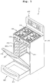
- Fig. 1 is a perspective view illustrating a gas oven 1 according to a first embodiment
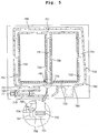
- Fig. 2 is a plan view illustrating a burner 500 disposed at an upper side of an oven chamber 211 according to the first embodiment
- Fig. 3 is a vertical sectional view illustrating a main part of the burner 500 according to the first embodiment.
- the oven range 1 includes a cook top part 100, an oven part 200, a drawer part 300, and a control part 400.
- the cook top part 100, the oven part 200, and the drawer part 300 are disposed at upper, middle, and lower regions of a main body 10 of the oven range 1, respectively.
- the control part 400 is disposed on the top of the main body 10 at a rear edge portion corresponding to a rear side of the cook top part 100.
- the oven part 200 includes an oven cavity 210 provided inside the main body 10.
- An oven chamber 211 and a burner chamber (not shown) are provided in the oven cavity 210.
- food is cooked, and in the burner chamber, a lower burner (not shown) is disposed for heating the food placed in the oven chamber 211 by convectional heat.
- the oven chamber 211 can be selectively closed and opened by using an oven door 220.
- the oven door 220 is a pull-down door of which the top end can be rotated up and down about the lower end.
- a door handle 221 is provided on a front upper portion of the oven door 220 so that a user can easily rotate the oven door 220 using the door handle 221.
- a container in which food is contained can be stored in the drawer part 300 at a predetermined temperature.
- the drawer part 300 includes a drawer 310 in which a container can be placed.
- a manipulation signal can be input (generated) through the control part 400 for operating the oven range 1, specifically, at least one of the oven part 200 and the drawer part 300.
- the control part 400 displays information about operational conditions of the oven range 1.
- the upper burner 500 is disposed at an upper side of the oven chamber 211.
- the upper burner 500 is used to burn a gaseous fuel to directly heat food placed in the oven chamber 211 by radiant heat.
- the upper burner 500 has a fork shape.
- the upper burner 500 includes a supply part 510, a distribution part 520, and three combustion parts 530, 540, and 550.
- the supply part 510, the distribution part 520, and the combustion parts 530, 540, and 550 may be formed in one piece.
- the supply part 510 is disposed at an upper rear part of the oven chamber 211 and has a shape elongated in a front-back direction.
- the supply part 510 functions as an inlet for receiving gas and air.
- a flow passage 511 is formed in the supply part 510. In the flow passage 511, gas and air are mixed.
- a plurality of flame holes 523 are formed in a front end of the distribution part 520. Some of a gas mixture flowing along the flow passage 521 of the distribution part 520 is burned at the flame holes 523. However, the flame holes 523 can be omitted.
- the combustion parts 530, 540, and 550 extend from the front end of the distribution part 520 opposite to the supply part 510 in a front-back direction of the oven chamber 211.
- the combustion parts 530, 540, and 550 includes a first combustion part 530 extending from a center part of the distribution part 520 in the front-back direction of the oven chamber 211, a second combustion part 540 extending from a lateral end portion of the distribution part 520 in the front-back direction of the oven chamber 211, and a third combustion part 550 extending from the other lateral end portion of the distribution part 520 in the front-back direction of the oven chamber 211.
- the first to third combustion parts 530, 540, and 550 are spaced from each other by a predetermined distance in the right-left direction of the oven chamber 211.
- the first combustion part 530 is substantially on the same line with the supply part 510.
- Flow passages 531, 541, and 551 are provided in the first to third combustion parts 530, 540, and 550, respectively, and are connected to the flow passage 521 of the distribution part 520.
- a gas mixture is transferred from the flow passage 521 of the distribution part 520 to the flow passages 531, 541, and 551 of the first to third combustion parts 530, 540, and 550.
- the supply part 510 and the first combustion part 530 are placed along the same line. Therefore, most of a gas mixture transferred from the flow passage 511 of the supply part 510 to the flow passage 521 of the distribution part 520 may be distributed to the first combustion part 530. That is, the gas mixture flowing in the flow passage 521 of the distribution part 520 may not be uniformly distributed to the first to third combustion parts 530, 540, and 550. Therefore, in the current embodiment, the distribution guide 570 is provided so that a gas mixture supplied from the flow passage 511 of the supply part 510 to the flow passage 521 of the distribution part 520 is not mainly distributed to the first combustion part 530. That is, a gas mixture supplied from the flow passage 511 of the supply part 510 to the flow passage 521 of the distribution part 520 can be uniformly distributed to the first to third combustion parts 530, 540, and 550.
- a user can input a manipulation signal by using the control part 400 for cooking food using the oven part 200. If a manipulation signal is input through the control part 400, the upper burner 500 (and the lower burner) is operated to cook food placed in the oven chamber 211.
- gas and air are supplied to the flow passage 511 of the supply part 510.
- the gas and air are mixed with each other as they flow along the flow passage 511 of the supply part 510.
- the gas mixture is transferred from the flow passage 511 of the supply part 510 to the flow passage 521 of the distribution part 520.
- Some of the gas mixture transferred to the flow passage 521 of the distribution part 520 is burned at the flame holes 523 of the distribution part 520 to form flames.
- the remaining gas mixture is transferred from the flow passage 521 of the distribution part 520 to the flow passages 531, 541, and 551 of the first to third combustion parts 530, 540, and 550.
- the gas mixture is not mainly distributed to the flow passage 531 of the first combustion part 530 but uniformly distributed to the first to third combustion parts 530, 540, and 550.
- the gas mixture transferred to the flow passages 531, 541, and 551 of the first to third combustion parts 530, 540, and 550 is burned at the flame holes 533, 543, and 553 of the first to third combustion parts 530, 540, and 550 to form flames.
- Fig. 4 is a plan view illustrating a burner disposed at an upper side of an oven chamber of a gas oven according to a second embodiment which is not part of the invention.
- the same elements as the first embodiment will be denoted by the reference numerals used in Fig. 1 , and detailed descriptions thereof will be omitted.
- an upper burner 600 which is disposed at an upper side of the oven chamber 211, includes a supply part 610, a distribution part 620, a plurality of combustion parts 630, 640, and 650, and a connection part 660.
- the supply part 610, the distribution part 620, the combustion parts 630, 640, and 650, and the connection part 660 may be formed in one piece.
- the supply part 610 transfers gas and air to the distribution part 620.
- a flow passage 611 is formed in the supply part 610. In the flow passage 611, gas and air are mixed.
- the supply part 610 extends from an upper rear side of the oven chamber 211 in a right-left direction of the oven chamber 211. Owing to this, the length of the supply part 610 may occupy less space in the oven chamber 211 so that the length of the combustion parts 630, 640, and 650 where combustion of a gas mixture is substantially performed can be increased for heating food efficiently. Gas and air supplied to an end of the supply part 610 are mixed with each other as they flow through the flow passage 611 of the supply part 610, and then the generates mixture is supplied to the distribution part 620 through the other end of the supply part 610.
- the distribution part 620 transfers the gas mixture to the combustion parts 630, 640, and 650. That is, the distribution part 620 distributes a gas mixture received from the supply part 610 to the combustion parts 630, 640, and 650.
- the distribution part 620 extends in the right-left direction of the oven chamber 211, and the other end of the supply part 610 is connected to a center part of the distribution part 620.
- the combustion parts 630, 640, and 650 includes a first combustion part 630 extending from the center part of the distribution part 620 in the front-back direction of the oven chamber 211, a second combustion part 640 extending from a lateral end portion of the distribution part 620 in the front-back direction of the oven chamber 211, and a third combustion part 650 extending from the other lateral end portion of the distribution part 620 in the front-back direction of the oven chamber 211.
- the first to third combustion parts 630, 640, and 650 include flow passages 631, 641, and 651, respectively, in which a gas mixture received from the distribution part 620 flows.
- the first to third combustion parts 630, 640, and 650 further include a plurality of flame holes 633, 643, and 653 where a gas mixture flowing along the flow passages 631, 641, and 651 is burned to form flames.
- connection part 660 connects front ends of the first to third combustion parts 630, 640, and 650. Therefore, the upper burner 600 can have a grating shape.
- the connection part 660 includes a flow passage 661 connected to the flow passages 631, 641, and 651 of the first to third combustion parts 630, 640, and 650.
- the connection part 660 includes a plurality of flame holes 663 for burning a gas mixture flowing in the flow passage 661 of the connection part 660.
- Two distribution guides 670 are disposed at a part where the supply part 610 and the distribution part 620 are connected (that is, where the flow passage 611 of the supply part 610 is connected to the flow passage 621 of the distribution part 620). Owing to the distribution guides 670, a gas mixture supplied from the flow passage 611 of the supply part 610 to the distribution part 620 can be uniformly distributed to the first to third combustion parts 630, 640, and 650.
- a gas mixture transferred to the distribution part 620 after flowing in the supply part 610 in a left-to-right direction of the oven chamber 211 is not mainly distributed to the flow passages 631 and 641 of the first and second distribution parts 630 and 640 but is uniformly distributed to the first to third combustion parts 630, 640, and 650.
- the two distribution guides 670 are disposed at an inner boundary part between the supply part 610 and the distribution part 620 which is close to a rear end of the first combustion part 630, and the distribution guides 670 are spaced apart from each other by a distance corresponding to the width of the first combustion part 630.
- Each of the distribution guides 670 has an approximate cylinder shape.
- the distribution guides 670 may be protrusions extending from the boundary part between the supply part 610 and the distribution part 620 toward the insides of the flow passages 611 and 621 of the supply part 610 and the distribution part 620.
- a user can input a manipulation signal by using the control part 400 (refer to Fig. 1 ) for using the oven part 200 (refer to Fig. 1 ). If a manipulation signal is input, the upper burner 600 (and the lower burner) is operated to cook food placed in the oven chamber 211.
- gas and air are supplied to the flow passage 611 of the supply part 610.
- the gas and air are mixed with each other as they flow along the flow passage 611 of the supply part 610, and then the gas mixture is transferred to the flow passage 621 of the distribution part 620. Thereafter, the gas mixture is distributed from the flow passage 621 of the distribution part 620 to the flow passages 631, 641, and 651 of the first to third combustion parts 630, 640, and 650.
- the gas mixture when the gas mixture is transferred from the flow passage 621 of the distribution part 620 to the flow passages 631, 641, and 651 of the first to third combustion parts 630, 640, and 650, the gas mixture can be uniformly distributed.
- the gas mixture transferred to the flow passages 631, 641, and 651 of the first to third combustion parts 630, 640, and 650 is burned at the flame holes 633, 643, and 653 of the first to third combustion parts 630, 640, and 650 to form flames, so that food placed in the oven chamber 211 can be cooked by direct radiant heat.
- Fig. 5 is a plan view illustrating a burner disposed at an upper side of an oven chamber of a gas oven according to the invention.
- the same elements as the first embodiment will be denoted by the reference numerals used in Fig. 1 , and detailed descriptions thereof will be omitted.
- an upper burner 700 which is disposed at an upper side of the oven chamber 211, includes a supply part 710, a distribution part 720, a plurality of combustion parts (first to third combustion parts) 730, 740, and 750, and a connection part 760.
- the upper burner 700 has substantially the same structure as the upper burner 600 of the second embodiment.
- connection part 760 has no flame hole.
- a distribution guide 770 is provided to uniformly distribute a gas mixture to the first to third combustion parts 730, 740, and 750.
- the distribution guide 770 has a hexahedral shape with a width corresponding to the width of the first combustion part 730.
- a neck part 780 is provided at a boundary part between the distribution part 720 and the second combustion part 740 for uniformly distributing a gas mixture to the first to third combustion parts 730, 740, and 750.
- a relatively large amount of a gas mixture may be distributed to the second combustion part 740 as compared with the first and third combustion parts 730 and 750, because the second combustion part 740 is located at an end portion of the distribution part 720 which is spaced apart from the center portion of the distribution part 720 in a direction where the gas mixture flows in the supply part 710.
- the neck part 780 is provided at the boundary part between the distribution part 720 and the second combustion part 740.
- the neck part 780 is formed by reducing the cross sectional area of the boundary part between the distribution part 720 and the second combustion part 740 as compared with the cross sectional areas of flow passages 721 and 741 of the distribution part 720 and the second combustion part 740. Therefore, a gas mixture flowing in the flow passage 721 of the distribution part 720 is not mainly distributed to the second combustion part 740 but is uniformly distributed to the first to third combustion parts 730, 740 and 750.
- a gas mixture transferred from the flow passage 721 of the distribution part 720 to the flow passage 741 of the second combustion part 740 may flow at an outer region of the flow passage 741 opposite to flame holes 743 of the second combustion part 740.
- the gas mixture may be not burned at some of the flame holes 743.
- the cross sectional area of the upstream side of the flow passage 741 of the second combustion part 740 close to the neck part 780 is increased relative to the cross sectional area of flow passages 731 and 751 of the first and third combustion parts 730 and 750. Therefore, the velocity of a gas mixture can be reduced at the upstream side of the flow passage 741 of the second combustion part 740, and thus the gas mixture can be uniformly burned at the flame holes 743 of the second combustion part 740.
- the cross sectional area of the flow passage 741 of the second combustion part 740 is decreased in a direction from the upstream side to the downstream side close to the connection part 760. Therefore, a gas mixture can be effectively burned at flame holes 743 of the second combustion part 740 located at the downstream side of the flow passage 741 where the flowrate of a gas mixture is relatively low.
- the upper burner 700 includes a plug assembly 790 configured to generate a spark for igniting a gas mixture.
- a gas mixture is ignited at a position between the distribution part 720 and the second combustion part 740.
- the plug assembly 790 includes a spark plug 791, a plug target 792, and a plug holder 794.
- a spark is generated between the spark plug 791 and the plug target 792 for igniting a gas mixture.
- the plug target 792 is formed of a metallic material and is spaced a predetermined distance from the spark plug 791. When power is applied to the spark plug 791, a spark is generated between the spark plug 791 and the plug target 792.
- the spark plug 791 and the plug target 792 are installed in the plug holder 794.
- the plug holder 794 is fixed to a bracket (not shown) disposed at a lower side of the upper burner 700.
- the spark plug 791 and the plug target 792 are horizontally placed.
- the spark plug 791 and the plug target 792 are substantially parallel with the first combustion part 730. Therefore, the plug assembly 790 does not largely increase the height of the upper burner 500.
- the plug assembly 790 ignites a gas mixture to be discharged through flame holes 733 of the first combustion part 730.
- a gas mixture to be discharged through flame holes 723 of the distribution part 720 is ignited.
- a flame formed at the gas mixture to be discharged through the flame holes 723 of the distribution part 720 a gas mixture to be discharged through flame holes 743 and 753 of the second and third combustion parts 740 and 750 is ignited.
- a flame formed on a gas mixture ignited at the first combustion part 730 by the plug assembly 790 is propagated to the second and third combustion parts 740 and 750 through the distribution part 720.
- food can be heated more uniformly.
- the burner and the gas oven including the burner provide the following effects.
- food placed in the oven chamber is heated by the burner disposed at the ceiling of the oven chamber and having a grate structure.
- flame holes are formed in both sides of the combustion part where gas is substantially burned. Therefore, food placed in the oven chamber can be heated more uniformly.
Landscapes
- Engineering & Computer Science (AREA)
- Chemical & Material Sciences (AREA)
- Combustion & Propulsion (AREA)
- Mechanical Engineering (AREA)
- General Engineering & Computer Science (AREA)
- Baking, Grill, Roasting (AREA)
- Gas Burners (AREA)
Description
- The present invention relates to a burner configured to combust gas for cooking food in a cooking device, in particular in a gas oven and to a gas oven including the burner.
- Gas ovens are used for cooking foods using a gaseous fuel. Such a gas oven includes an oven chamber in which food is cooked, and a burner configured to burn a gaseous fuel for cooking food accommodated in the oven chamber. The burner can be installed on the ceiling of the oven chamber for generating a flame by burning a gaseous fuel and heat food placed in the oven chamber by radiant heat from the flame. However, in the related art, since the burner is disposed at a center portion of the ceiling of the oven chamber, food placed in the oven chamber may not be uniformly heated.
- A burner according to the preamble of claim 1 is known from
JPH10019209 - The object of the present invention is to provide a burner configured to heat food more uniformly and a gas oven including the burner. This object is achieved by providing a burner according to the object of claim 1.
- A gas oven according to the present invention includes an oven chamber in which food is cooked; and a burner according to the present invention, wherein the burner is disposed at a side of the oven chamber for providing heat to food disposed in the oven chamber for cooking the same.
- The details of one or more embodiments are set forth in the accompanying drawings and the description below. Other features will be apparent from the description and drawings, and from the claims.
-
-
Fig. 1 is a perspective view illustrating a gas oven according to a first embodiment. -
Fig. 2 is a plan view illustrating a burner which is not part of the present invention and which is disposed at an upper side of an oven chamber according to the first embodiment. -
Fig. 3 is a vertical sectional view illustrating a main part of the burner according to the first embodiment which is not part of the present invention. -
Fig. 4 is a plan view illustrating a burner disposed at an upper side of an oven chamber of a gas oven according to a second embodiment which is not part of the present invention. -
Fig. 5 is a plan view illustrating a burner disposed at an upper side of an oven chamber of a gas oven according to the invention. - Hereinafter, a gas oven will be explained in detail with reference to the accompanying drawings according to a first embodiment.
-
Fig. 1 is a perspective view illustrating a gas oven 1 according to a first embodiment;Fig. 2 is a plan view illustrating aburner 500 disposed at an upper side of anoven chamber 211 according to the first embodiment; andFig. 3 is a vertical sectional view illustrating a main part of theburner 500 according to the first embodiment. - Referring to
Fig. 1 , the oven range 1 includes a cooktop part 100, anoven part 200, adrawer part 300, and acontrol part 400. The cooktop part 100, theoven part 200, and thedrawer part 300 are disposed at upper, middle, and lower regions of amain body 10 of the oven range 1, respectively. Thecontrol part 400 is disposed on the top of themain body 10 at a rear edge portion corresponding to a rear side of the cooktop part 100. - In more detail, the cook
top part 100 includes a plurality of cook-top burners 110. Each of the cook-top burners 110 can generate a flame by burning a gaseous fuel to directly heat a container in which food is placed. A plurality ofknobs 120 are disposed on a front end portion of the cooktop part 100. Theknobs 120 are used to close, open, or adjust valves (not shown) for starting, stopping, or adjusting supply of a gaseous fuel to the cook-top burners 110. - The
oven part 200 includes anoven cavity 210 provided inside themain body 10. Anoven chamber 211 and a burner chamber (not shown) are provided in theoven cavity 210. In theoven chamber 211, food is cooked, and in the burner chamber, a lower burner (not shown) is disposed for heating the food placed in theoven chamber 211 by convectional heat. - The
oven chamber 211 can be selectively closed and opened by using anoven door 220. Theoven door 220 is a pull-down door of which the top end can be rotated up and down about the lower end. Adoor handle 221 is provided on a front upper portion of theoven door 220 so that a user can easily rotate theoven door 220 using thedoor handle 221. - A container in which food is contained can be stored in the
drawer part 300 at a predetermined temperature. Thedrawer part 300 includes adrawer 310 in which a container can be placed. - A manipulation signal can be input (generated) through the
control part 400 for operating the oven range 1, specifically, at least one of theoven part 200 and thedrawer part 300. In addition, thecontrol part 400 displays information about operational conditions of the oven range 1. - Referring to
Figs. 2 and3 , theupper burner 500 is disposed at an upper side of theoven chamber 211. Theupper burner 500 is used to burn a gaseous fuel to directly heat food placed in theoven chamber 211 by radiant heat. Theupper burner 500 has a fork shape. Theupper burner 500 includes asupply part 510, adistribution part 520, and threecombustion parts supply part 510, thedistribution part 520, and thecombustion parts - In more detail, the
supply part 510 is disposed at an upper rear part of theoven chamber 211 and has a shape elongated in a front-back direction. Thesupply part 510 functions as an inlet for receiving gas and air. Aflow passage 511 is formed in thesupply part 510. In theflow passage 511, gas and air are mixed. - The
distribution part 520 extends from a front end of thesupply part 510 toward left and right sides of theoven chamber 211. Thedistribution part 520 may be symmetric with respect to thesupply part 510. Thedistribution part 520 includes aflow passage 521 connected to theflow passage 511 of thesupply part 510. A gas mixture is transferred from theflow passage 511 of thesupply part 510 to theflow passage 521 of thedistribution part 520 where the gas mixture is distributed to thecombustion parts - In the current embodiment, a plurality of
flame holes 523 are formed in a front end of thedistribution part 520. Some of a gas mixture flowing along theflow passage 521 of thedistribution part 520 is burned at theflame holes 523. However, theflame holes 523 can be omitted. - The
combustion parts distribution part 520 opposite to thesupply part 510 in a front-back direction of theoven chamber 211. Thecombustion parts first combustion part 530 extending from a center part of thedistribution part 520 in the front-back direction of theoven chamber 211, asecond combustion part 540 extending from a lateral end portion of thedistribution part 520 in the front-back direction of theoven chamber 211, and athird combustion part 550 extending from the other lateral end portion of thedistribution part 520 in the front-back direction of theoven chamber 211. Therefore, the first tothird combustion parts oven chamber 211. Thefirst combustion part 530 is substantially on the same line with thesupply part 510.Flow passages third combustion parts flow passage 521 of thedistribution part 520. A gas mixture is transferred from theflow passage 521 of thedistribution part 520 to theflow passages third combustion parts flame holes third combustion parts flow passages third combustion parts flame holes - A
distribution guide 570 is disposed at a cross point of thesupply part 510, thedistribution part 520, and thefirst combustion part 530. In other words, thedistribution guide 570 is disposed in theflow passage 521 of thedistribution part 520 between thesupply part 510 and thefirst combustion part 530. Owing to thedistribution guide 570, a gas mixture flowing from theflow passage 511 of thesupply part 510 to theflow passage 521 of thedistribution part 520 can be uniformly distributed to the first tothird combustion parts distribution guide 570 may be a protrusion extending from thedistribution part 520 into theflow passage 521. In the current embodiment, thedistribution guide 570 has an approximate cylinder shape. - In more detail, the
supply part 510 and thefirst combustion part 530 are placed along the same line. Therefore, most of a gas mixture transferred from theflow passage 511 of thesupply part 510 to theflow passage 521 of thedistribution part 520 may be distributed to thefirst combustion part 530. That is, the gas mixture flowing in theflow passage 521 of thedistribution part 520 may not be uniformly distributed to the first tothird combustion parts distribution guide 570 is provided so that a gas mixture supplied from theflow passage 511 of thesupply part 510 to theflow passage 521 of thedistribution part 520 is not mainly distributed to thefirst combustion part 530. That is, a gas mixture supplied from theflow passage 511 of thesupply part 510 to theflow passage 521 of thedistribution part 520 can be uniformly distributed to the first tothird combustion parts - Hereinafter, operations of the gas oven 1 will be described in detail according to the first embodiment which is not part of the present invention.
- A user can input a manipulation signal by using the
control part 400 for cooking food using theoven part 200. If a manipulation signal is input through thecontrol part 400, the upper burner 500 (and the lower burner) is operated to cook food placed in theoven chamber 211. - In more detail, gas and air are supplied to the
flow passage 511 of thesupply part 510. The gas and air are mixed with each other as they flow along theflow passage 511 of thesupply part 510. - Then, the gas mixture is transferred from the
flow passage 511 of thesupply part 510 to theflow passage 521 of thedistribution part 520. Some of the gas mixture transferred to theflow passage 521 of thedistribution part 520 is burned at the flame holes 523 of thedistribution part 520 to form flames. The remaining gas mixture is transferred from theflow passage 521 of thedistribution part 520 to theflow passages third combustion parts - At this time, owning to the
distribution guide 570 provided in theflow passage 521 of thedistribution part 520, the gas mixture is not mainly distributed to theflow passage 531 of thefirst combustion part 530 but uniformly distributed to the first tothird combustion parts flow passages third combustion parts third combustion parts - In this way, flames are formed by a gas mixture burned at the flame holes 523 of the
distribution part 520 and the flame holes 533, 543, and 553 of the first tothird combustion parts oven chamber 211 can be heated by direct radiant heat. That is, food placed in theoven chamber 211 can be uniformly heated by heat from the flames at thedistribution part 520 and at the first tothird combustion parts - Hereinafter, a gas oven will be explained in detail with reference to the accompanying drawing according to a second embodiment.
-
Fig. 4 is a plan view illustrating a burner disposed at an upper side of an oven chamber of a gas oven according to a second embodiment which is not part of the invention. In the current embodiment, the same elements as the first embodiment will be denoted by the reference numerals used inFig. 1 , and detailed descriptions thereof will be omitted. - Referring to
Fig. 4 , anupper burner 600, which is disposed at an upper side of theoven chamber 211, includes asupply part 610, adistribution part 620, a plurality ofcombustion parts connection part 660. Thesupply part 610, thedistribution part 620, thecombustion parts connection part 660 may be formed in one piece. - The
supply part 610 transfers gas and air to thedistribution part 620. Aflow passage 611 is formed in thesupply part 610. In theflow passage 611, gas and air are mixed. In the current embodiment, thesupply part 610 extends from an upper rear side of theoven chamber 211 in a right-left direction of theoven chamber 211. Owing to this, the length of thesupply part 610 may occupy less space in theoven chamber 211 so that the length of thecombustion parts supply part 610 are mixed with each other as they flow through theflow passage 611 of thesupply part 610, and then the generates mixture is supplied to thedistribution part 620 through the other end of thesupply part 610. - The
distribution part 620 transfers the gas mixture to thecombustion parts distribution part 620 distributes a gas mixture received from thesupply part 610 to thecombustion parts distribution part 620 extends in the right-left direction of theoven chamber 211, and the other end of thesupply part 610 is connected to a center part of thedistribution part 620. - The
combustion parts first combustion part 630 extending from the center part of thedistribution part 620 in the front-back direction of theoven chamber 211, asecond combustion part 640 extending from a lateral end portion of thedistribution part 620 in the front-back direction of theoven chamber 211, and a third combustion part 650 extending from the other lateral end portion of thedistribution part 620 in the front-back direction of theoven chamber 211. The first tothird combustion parts flow passages distribution part 620 flows. The first tothird combustion parts flame holes flow passages - The
connection part 660 connects front ends of the first tothird combustion parts upper burner 600 can have a grating shape. Theconnection part 660 includes aflow passage 661 connected to theflow passages third combustion parts connection part 660 includes a plurality offlame holes 663 for burning a gas mixture flowing in theflow passage 661 of theconnection part 660. - Two distribution guides 670 are disposed at a part where the
supply part 610 and thedistribution part 620 are connected (that is, where theflow passage 611 of thesupply part 610 is connected to theflow passage 621 of the distribution part 620). Owing to the distribution guides 670, a gas mixture supplied from theflow passage 611 of thesupply part 610 to thedistribution part 620 can be uniformly distributed to the first tothird combustion parts distribution part 620 after flowing in thesupply part 610 in a left-to-right direction of theoven chamber 211 is not mainly distributed to theflow passages second distribution parts third combustion parts supply part 610 and thedistribution part 620 which is close to a rear end of thefirst combustion part 630, and the distribution guides 670 are spaced apart from each other by a distance corresponding to the width of thefirst combustion part 630. Each of the distribution guides 670 has an approximate cylinder shape. The distribution guides 670 may be protrusions extending from the boundary part between thesupply part 610 and thedistribution part 620 toward the insides of theflow passages supply part 610 and thedistribution part 620. - Hereinafter, operations of the gas oven will be described in detail according to the second embodiment.
- A user can input a manipulation signal by using the control part 400 (refer to
Fig. 1 ) for using the oven part 200 (refer toFig. 1 ). If a manipulation signal is input, the upper burner 600 (and the lower burner) is operated to cook food placed in theoven chamber 211. - When the
upper burner 600 is operated, gas and air are supplied to theflow passage 611 of thesupply part 610. The gas and air are mixed with each other as they flow along theflow passage 611 of thesupply part 610, and then the gas mixture is transferred to theflow passage 621 of thedistribution part 620. Thereafter, the gas mixture is distributed from theflow passage 621 of thedistribution part 620 to theflow passages third combustion parts - At this time, owning to the distribution guides 670, when the gas mixture is transferred from the
flow passage 621 of thedistribution part 620 to theflow passages third combustion parts flow passages third combustion parts third combustion parts oven chamber 211 can be cooked by direct radiant heat. - Hereinafter, a gas oven will be described in detail with reference to the accompanying drawing according to a third embodiment.
-
Fig. 5 is a plan view illustrating a burner disposed at an upper side of an oven chamber of a gas oven according to the invention. In the current embodiment, the same elements as the first embodiment will be denoted by the reference numerals used inFig. 1 , and detailed descriptions thereof will be omitted. - Referring to
Fig. 5 , anupper burner 700, which is disposed at an upper side of theoven chamber 211, includes asupply part 710, adistribution part 720, a plurality of combustion parts (first to third combustion parts) 730, 740, and 750, and aconnection part 760. Theupper burner 700 has substantially the same structure as theupper burner 600 of the second embodiment. - In the current embodiment, the
connection part 760 has no flame hole. Adistribution guide 770 is provided to uniformly distribute a gas mixture to the first tothird combustion parts distribution guide 770 has a hexahedral shape with a width corresponding to the width of thefirst combustion part 730. - According to the present invention, a
neck part 780 is provided at a boundary part between thedistribution part 720 and thesecond combustion part 740 for uniformly distributing a gas mixture to the first tothird combustion parts second combustion part 740 as compared with the first andthird combustion parts 730 and 750, because thesecond combustion part 740 is located at an end portion of thedistribution part 720 which is spaced apart from the center portion of thedistribution part 720 in a direction where the gas mixture flows in thesupply part 710. To prevent this, according to the present invention, theneck part 780 is provided at the boundary part between thedistribution part 720 and thesecond combustion part 740. - The
neck part 780 is formed by reducing the cross sectional area of the boundary part between thedistribution part 720 and thesecond combustion part 740 as compared with the cross sectional areas offlow passages distribution part 720 and thesecond combustion part 740. Therefore, a gas mixture flowing in theflow passage 721 of thedistribution part 720 is not mainly distributed to thesecond combustion part 740 but is uniformly distributed to the first tothird combustion parts - Since the cross sectional area of the boundary part between the
distribution part 720 and thesecond combustion part 740 is reduced due to theneck part 780, the velocity of a gas mixture increases at the boundary part. Therefore, a gas mixture transferred from theflow passage 721 of thedistribution part 720 to theflow passage 741 of thesecond combustion part 740 may flow at an outer region of theflow passage 741 opposite to flameholes 743 of thesecond combustion part 740. In this case, the gas mixture may be not burned at some of the flame holes 743. To prevent this, in the current embodiment, the cross sectional area of the upstream side of theflow passage 741 of thesecond combustion part 740 close to theneck part 780 is increased relative to the cross sectional area offlow passages third combustion parts 730 and 750. Therefore, the velocity of a gas mixture can be reduced at the upstream side of theflow passage 741 of thesecond combustion part 740, and thus the gas mixture can be uniformly burned at the flame holes 743 of thesecond combustion part 740. In addition, the cross sectional area of theflow passage 741 of thesecond combustion part 740 is decreased in a direction from the upstream side to the downstream side close to theconnection part 760. Therefore, a gas mixture can be effectively burned atflame holes 743 of thesecond combustion part 740 located at the downstream side of theflow passage 741 where the flowrate of a gas mixture is relatively low. - The
upper burner 700 includes aplug assembly 790 configured to generate a spark for igniting a gas mixture. In the current embodiment, a gas mixture is ignited at a position between thedistribution part 720 and thesecond combustion part 740. Theplug assembly 790 includes aspark plug 791, aplug target 792, and aplug holder 794. - A spark is generated between the
spark plug 791 and theplug target 792 for igniting a gas mixture. Theplug target 792 is formed of a metallic material and is spaced a predetermined distance from thespark plug 791. When power is applied to thespark plug 791, a spark is generated between thespark plug 791 and theplug target 792. - The
spark plug 791 and theplug target 792 are installed in theplug holder 794. Theplug holder 794 is fixed to a bracket (not shown) disposed at a lower side of theupper burner 700. - The
spark plug 791 and theplug target 792 are horizontally placed. Thespark plug 791 and theplug target 792 are substantially parallel with thefirst combustion part 730. Therefore, theplug assembly 790 does not largely increase the height of theupper burner 500. - The
plug assembly 790 ignites a gas mixture to be discharged throughflame holes 733 of thefirst combustion part 730. By a flame formed at the gas mixture to be discharged through the flame holes 733 of thefirst combustion part 730, a gas mixture to be discharged throughflame holes 723 of thedistribution part 720 is ignited. By a flame formed at the gas mixture to be discharged through the flame holes 723 of thedistribution part 720, a gas mixture to be discharged throughflame holes third combustion parts 740 and 750 is ignited. In other words, a flame formed on a gas mixture ignited at thefirst combustion part 730 by theplug assembly 790 is propagated to the second andthird combustion parts 740 and 750 through thedistribution part 720. - According to the present disclosure, food can be heated more uniformly.
- As described above, according to the present disclosure, the burner and the gas oven including the burner provide the following effects.
- According to the embodiments of the present disclosure, food placed in the oven chamber is heated by the burner disposed at the ceiling of the oven chamber and having a grate structure. In addition, flame holes are formed in both sides of the combustion part where gas is substantially burned. Therefore, food placed in the oven chamber can be heated more uniformly.
- In addition, owing to the distribution guide, gas can be uniformly distributed to the combustion parts. Therefore, food can be uniformly cooked in the oven chamber.
- Although embodiments have been described with reference to a number of illustrative embodiments thereof, it should be understood that numerous other modifications and embodiments can be devised by those skilled in the art.
Claims (12)
- A burner (700) for cooking food in a cooking device, comprising:a flow passage (731, 741, 751) through which gas flows, the flow passage (731, 741, 751) having a fork or grating shape is provided by:a supply part (710) configured to supply gas;a distribution part (720) configured to receive gas from the supply part (710); anda plurality of parallel combustion parts (730, 740, 750) comprising a plurality of flame holes (733, 743, 753), which are formed in at least one side of the combustion parts (730, 740, 750) in a direction perpendicular to a gas flow direction for receiving gas from the distribution part (720) so as to allow gas or a mixture of gas and air to be burned at the flame holes,wherein the supply part (710) and the distribution part (720) extend in parallel with each other,characterized by further comprising a neck part (780) at a position from which one of the combustion parts (740) branches off from the distribution part (720), the neck part (780) having a cross sectional area smaller than a cross sectional area of the one of the combustion parts (730, 740, 750);and by the neck part (780) being disposed at a position from which the most downstream one of the combustion parts in a direction in which gas is transferred from the supply part (710) to the distribution part (720) is branched off from the distribution part (720).
- The burner (700) according to claim 1, wherein the distribution part (720) is connected to an end of the supply part (710) and is elongated in a direction parallel or perpendicular to the supply part (710), and the combustion parts (730, 740, 750) branch off from the distribution part (720) and extend substantially in a direction perpendicular to the distribution part (720).
- The burner (700) according to claim 1 or 2, further comprising a connection part (760) configured to connect ends of the combustion parts such that some of gas flowing in the combustion parts (730, 740, 750) is transferred to the connecting part (760).
- The burner (700) according to any one of claims 1 to 3, wherein the supply part (710), the distribution part (720), and the combustion parts (730, 740, 750) are formed in one piece.
- The burner (700) according to any one of claims 1 to 4, further comprising a distribution guide disposed in the flow passage such that gas or a mixture of gas and air supplied to one combustion part or branch of the flow passage is uniformly distributed to other combustion parts or branches of the flow passage.
- The burner (700) according to claim 5, wherein one of the combustion parts is placed along a line in a direction in which gas is transferred from the supply part (710) to the distribution part (720), and
the distribution guide is disposed at a position from which the one of the combustion parts (730, 740, 750) branches off from the distribution part (720). - The burner (700) according to claim 5, wherein the distribution guide is disposed at a position at which the flow passage (731, 741, 751) is divided into two or more branches in different directions or at a position in the flow passage (731, 741, 751) along which gas is transferred from the supply part to the distribution part (720).
- The burner (700) according to any one of claims 5 to 7, wherein the distribution protrusion is formed by protruding a portion of at least one of the distribution part and the combustion parts into a gas flow passage.
- The burner (700) according to any one of claims 1 to 8, wherein the cross sectional area of the one of the combustion parts (730, 740, 750) decreases from an upstream side to a downstream side of a gas flow.
- The burner (700) according to any one of claims 1 to 9, further comprising a plug assembly configured to ignite gas at the combustion parts (730, 740, 750), wherein the plug assembly is preferably disposed to ignite gas to be discharged through the first combustion part (730, 740, 750) to form a flame, and the flame propagates along the distribution part to gas to be discharged through the second combustion part (740) and the third combustion part (750).
- A gas oven (1) comprising:an oven chamber (211) in which food is cooked; anda burner (700) according to any one of claims 1 to 10, the burner (700) being disposed in the oven chamber (211) for provide heat to food disposed in the oven chamber (211) for cooking the same.
- The gas oven (1) according to claim 11, wherein the combustion parts of the burner are disposed at an upper part of the oven chamber.
Applications Claiming Priority (4)
| Application Number | Priority Date | Filing Date | Title |
|---|---|---|---|
| KR1020080075779A KR101040432B1 (en) | 2008-08-01 | 2008-08-01 | Burner and gas oven including the same |
| KR1020080075773A KR101040458B1 (en) | 2008-08-01 | 2008-08-01 | Burner and gas oven including the same |
| KR1020090033887A KR101040405B1 (en) | 2009-04-17 | 2009-04-17 | Burners and Cookers |
| KR1020090033883A KR101040404B1 (en) | 2009-04-17 | 2009-04-17 | Burners and Cookers |
Publications (3)
| Publication Number | Publication Date |
|---|---|
| EP2149750A2 EP2149750A2 (en) | 2010-02-03 |
| EP2149750A3 EP2149750A3 (en) | 2015-07-01 |
| EP2149750B1 true EP2149750B1 (en) | 2018-07-18 |
Family
ID=41258448
Family Applications (1)
| Application Number | Title | Priority Date | Filing Date |
|---|---|---|---|
| EP09009951.6A Not-in-force EP2149750B1 (en) | 2008-08-01 | 2009-07-31 | Burner and gas oven including the same |
Country Status (3)
| Country | Link |
|---|---|
| US (1) | US20110186038A1 (en) |
| EP (1) | EP2149750B1 (en) |
| WO (1) | WO2010013929A2 (en) |
Families Citing this family (4)
| Publication number | Priority date | Publication date | Assignee | Title |
|---|---|---|---|---|
| KR101710202B1 (en) * | 2010-02-09 | 2017-02-24 | 엘지전자 주식회사 | Gas oven range |
| KR101724701B1 (en) * | 2010-07-15 | 2017-04-07 | 엘지전자 주식회사 | Gas burner |
| US9188343B2 (en) | 2013-01-15 | 2015-11-17 | General Electric Company | Oven appliance and a gas burner assembly for the same |
| US9504351B2 (en) * | 2013-10-11 | 2016-11-29 | Haler U.S. Appliance Solutions, Inc. | Double oven appliance |
Family Cites Families (25)
| Publication number | Priority date | Publication date | Assignee | Title |
|---|---|---|---|---|
| FR748817A (en) * | 1933-07-07 | |||
| US1194396A (en) * | 1916-08-15 | Island | ||
| US1625623A (en) * | 1922-09-21 | 1927-04-19 | Standard Gas Equipment Corp | Gas-stove burner |
| US3446566A (en) * | 1967-05-01 | 1969-05-27 | Teledyne Inc | Compact high capacity gas burner |
| US3635644A (en) * | 1970-01-19 | 1972-01-18 | Columbia Gas Syst | Infrared burner and method of increasing the heat flux radiated therefrom |
| US3871355A (en) * | 1973-03-23 | 1975-03-18 | Donald L Henry | Gas distribution apparatus for artificial logs |
| US3991941A (en) * | 1975-01-24 | 1976-11-16 | Dornback Furnace And Foundry Co. | Gas burner |
| US4020821A (en) * | 1975-03-10 | 1977-05-03 | Columbia Gas System Service Corporation | Gas-fired smooth top range |
| JPH0612090B2 (en) * | 1985-06-24 | 1994-02-16 | 本田技研工業株式会社 | Idle speed controller for internal combustion engine |
| US4676221A (en) * | 1985-09-23 | 1987-06-30 | Turco Incorporated Company | Barbecue grill with uniformly-heated heating chamber |
| DE3872075T2 (en) * | 1987-07-13 | 1993-02-11 | Matsushita Electric Ind Co Ltd | DEVICE FOR GAS COMBUSTION. |
| US5176512A (en) * | 1991-03-13 | 1993-01-05 | Lennox Industries Inc. | Inshot burner cluster apparatus |
| US5275147A (en) * | 1993-03-24 | 1994-01-04 | Aktinson Iii Benjamin E | Gas electric range apparatus |
| KR0133637Y1 (en) * | 1995-11-18 | 1999-03-20 | 배순훈 | Burner structure of gas oven |
| JP3207119B2 (en) * | 1996-07-05 | 2001-09-10 | リンナイ株式会社 | Burners for gas appliances |
| DE19941275C2 (en) * | 1999-08-31 | 2001-08-02 | Uwe Ebertz | Pipe hole burner for gas-fired grills |
| ITSV20020015A1 (en) * | 2002-04-19 | 2003-10-20 | Cast Srl | BURNER FOR OVEN OR GRILL VENTURI TUBE BRACKET SUPPORTING A THERMOCOUPLE AND / OR A SPARK PLUG AND PROCEDURE FOR THE FAB |
| US6672302B1 (en) * | 2002-07-25 | 2004-01-06 | Wayne/Scott Fetzer Company | Gas burner |
| US20040177870A1 (en) * | 2003-03-10 | 2004-09-16 | Wilson Donald W. | Curb and sidewalk cleaner |
| US6830045B2 (en) * | 2003-03-12 | 2004-12-14 | Maytag Corporation | Gas burner module for a cooking appliance |
| US20050056268A1 (en) * | 2003-09-17 | 2005-03-17 | General Electric Company | Gas burner for a cooking appliance |
| US20060081237A1 (en) * | 2004-10-14 | 2006-04-20 | Kiosky Chung | Stove body for large-scale barbecue stove |
| JP2008008569A (en) * | 2006-06-30 | 2008-01-17 | World Seiki:Kk | Burner for gas combustion, gas oven provided therewith, and method for reducing production amount of carbon monoxide in burner for gas combustion |
| US20090205631A1 (en) * | 2008-02-20 | 2009-08-20 | Kao Hsung Tsung | Gas burner head |
| CN101889172B (en) * | 2008-06-23 | 2013-04-03 | 萨巴夫股份有限公司 | Gas burner for ovens or grills |
-
2009
- 2009-07-28 US US13/056,584 patent/US20110186038A1/en not_active Abandoned
- 2009-07-28 WO PCT/KR2009/004199 patent/WO2010013929A2/en not_active Ceased
- 2009-07-31 EP EP09009951.6A patent/EP2149750B1/en not_active Not-in-force
Non-Patent Citations (1)
| Title |
|---|
| None * |
Also Published As
| Publication number | Publication date |
|---|---|
| WO2010013929A2 (en) | 2010-02-04 |
| EP2149750A3 (en) | 2015-07-01 |
| EP2149750A2 (en) | 2010-02-03 |
| US20110186038A1 (en) | 2011-08-04 |
| WO2010013929A3 (en) | 2010-05-06 |
Similar Documents
| Publication | Publication Date | Title |
|---|---|---|
| US8978637B2 (en) | Top burner and cooker comprising the same | |
| WO2009078673A2 (en) | A top-burner and cooker comprising the same | |
| AU2009210553A1 (en) | Open loop gas burner | |
| EP2241818B1 (en) | Burner and cooking device | |
| CA2732369C (en) | Reflector and gas oven range comprising the same | |
| US9188343B2 (en) | Oven appliance and a gas burner assembly for the same | |
| EP2149750A2 (en) | Burner and gas oven including the same | |
| KR101824736B1 (en) | A burner and cooker comprising the same | |
| EP2241819B1 (en) | Cooking device | |
| US20140196713A1 (en) | Gas burner assembly for an oven appliance | |
| KR100938201B1 (en) | Burner and cooking appliance comprising the same | |
| EP2161503B1 (en) | Reflector and gas oven range comprising the same | |
| KR100927328B1 (en) | Burner and cooking appliance comprising the same | |
| JP7526612B2 (en) | Grill burners and cooking appliances | |
| KR100938200B1 (en) | Burner and cooking appliance comprising the same | |
| KR101710202B1 (en) | Gas oven range | |
| KR101220624B1 (en) | Upper Burner Struture of Grill Part of Gas Range | |
| KR101040404B1 (en) | Burners and Cookers | |
| KR101040427B1 (en) | Reflector and gas oven range including the same | |
| KR101623981B1 (en) | Cooking appliance | |
| KR20100012244A (en) | Burner and gas oven range comprising the same | |
| KR920003238Y1 (en) | Heating apparatus | |
| KR101665708B1 (en) | Gas oven range | |
| KR101040432B1 (en) | Burner and gas oven including the same | |
| US9897323B2 (en) | Gas oven |
Legal Events
| Date | Code | Title | Description |
|---|---|---|---|
| PUAI | Public reference made under article 153(3) epc to a published international application that has entered the european phase |
Free format text: ORIGINAL CODE: 0009012 |
|
| AK | Designated contracting states |
Kind code of ref document: A2 Designated state(s): AT BE BG CH CY CZ DE DK EE ES FI FR GB GR HR HU IE IS IT LI LT LU LV MC MK MT NL NO PL PT RO SE SI SK SM TR |
|
| AX | Request for extension of the european patent |
Extension state: AL BA RS |
|
| PUAL | Search report despatched |
Free format text: ORIGINAL CODE: 0009013 |
|
| AK | Designated contracting states |
Kind code of ref document: A3 Designated state(s): AT BE BG CH CY CZ DE DK EE ES FI FR GB GR HR HU IE IS IT LI LT LU LV MC MK MT NL NO PL PT RO SE SI SK SM TR |
|
| AX | Request for extension of the european patent |
Extension state: AL BA RS |
|
| RIC1 | Information provided on ipc code assigned before grant |
Ipc: F23D 14/10 20060101AFI20150526BHEP Ipc: F24C 3/08 20060101ALI20150526BHEP |
|
| 17P | Request for examination filed |
Effective date: 20151130 |
|
| RBV | Designated contracting states (corrected) |
Designated state(s): AT BE BG CH CY CZ DE DK EE ES FI FR GB GR HR HU IE IS IT LI LT LU LV MC MK MT NL NO PL PT RO SE SI SK SM TR |
|
| GRAP | Despatch of communication of intention to grant a patent |
Free format text: ORIGINAL CODE: EPIDOSNIGR1 |
|
| INTG | Intention to grant announced |
Effective date: 20180228 |
|
| RAP1 | Party data changed (applicant data changed or rights of an application transferred) |
Owner name: LG ELECTRONICS INC. |
|
| GRAS | Grant fee paid |
Free format text: ORIGINAL CODE: EPIDOSNIGR3 |
|
| GRAA | (expected) grant |
Free format text: ORIGINAL CODE: 0009210 |
|
| AK | Designated contracting states |
Kind code of ref document: B1 Designated state(s): AT BE BG CH CY CZ DE DK EE ES FI FR GB GR HR HU IE IS IT LI LT LU LV MC MK MT NL NO PL PT RO SE SI SK SM TR |
|
| REG | Reference to a national code |
Ref country code: GB Ref legal event code: FG4D |
|
| REG | Reference to a national code |
Ref country code: CH Ref legal event code: EP |
|
| REG | Reference to a national code |
Ref country code: IE Ref legal event code: FG4D |
|
| REG | Reference to a national code |
Ref country code: DE Ref legal event code: R096 Ref document number: 602009053278 Country of ref document: DE |
|
| REG | Reference to a national code |
Ref country code: AT Ref legal event code: REF Ref document number: 1019768 Country of ref document: AT Kind code of ref document: T Effective date: 20180815 |
|
| REG | Reference to a national code |
Ref country code: FR Ref legal event code: PLFP Year of fee payment: 10 |
|
| PGFP | Annual fee paid to national office [announced via postgrant information from national office to epo] |
Ref country code: GB Payment date: 20180523 Year of fee payment: 10 |
|
| REG | Reference to a national code |
Ref country code: NL Ref legal event code: MP Effective date: 20180718 |
|
| REG | Reference to a national code |
Ref country code: LT Ref legal event code: MG4D |
|
| REG | Reference to a national code |
Ref country code: AT Ref legal event code: MK05 Ref document number: 1019768 Country of ref document: AT Kind code of ref document: T Effective date: 20180718 |
|
| PG25 | Lapsed in a contracting state [announced via postgrant information from national office to epo] |
Ref country code: NL Free format text: LAPSE BECAUSE OF FAILURE TO SUBMIT A TRANSLATION OF THE DESCRIPTION OR TO PAY THE FEE WITHIN THE PRESCRIBED TIME-LIMIT Effective date: 20180718 |
|
| PG25 | Lapsed in a contracting state [announced via postgrant information from national office to epo] |
Ref country code: NO Free format text: LAPSE BECAUSE OF FAILURE TO SUBMIT A TRANSLATION OF THE DESCRIPTION OR TO PAY THE FEE WITHIN THE PRESCRIBED TIME-LIMIT Effective date: 20181018 Ref country code: BG Free format text: LAPSE BECAUSE OF FAILURE TO SUBMIT A TRANSLATION OF THE DESCRIPTION OR TO PAY THE FEE WITHIN THE PRESCRIBED TIME-LIMIT Effective date: 20181018 Ref country code: SE Free format text: LAPSE BECAUSE OF FAILURE TO SUBMIT A TRANSLATION OF THE DESCRIPTION OR TO PAY THE FEE WITHIN THE PRESCRIBED TIME-LIMIT Effective date: 20180718 Ref country code: GR Free format text: LAPSE BECAUSE OF FAILURE TO SUBMIT A TRANSLATION OF THE DESCRIPTION OR TO PAY THE FEE WITHIN THE PRESCRIBED TIME-LIMIT Effective date: 20181019 Ref country code: AT Free format text: LAPSE BECAUSE OF FAILURE TO SUBMIT A TRANSLATION OF THE DESCRIPTION OR TO PAY THE FEE WITHIN THE PRESCRIBED TIME-LIMIT Effective date: 20180718 Ref country code: PL Free format text: LAPSE BECAUSE OF FAILURE TO SUBMIT A TRANSLATION OF THE DESCRIPTION OR TO PAY THE FEE WITHIN THE PRESCRIBED TIME-LIMIT Effective date: 20180718 Ref country code: IS Free format text: LAPSE BECAUSE OF FAILURE TO SUBMIT A TRANSLATION OF THE DESCRIPTION OR TO PAY THE FEE WITHIN THE PRESCRIBED TIME-LIMIT Effective date: 20181118 Ref country code: FI Free format text: LAPSE BECAUSE OF FAILURE TO SUBMIT A TRANSLATION OF THE DESCRIPTION OR TO PAY THE FEE WITHIN THE PRESCRIBED TIME-LIMIT Effective date: 20180718 Ref country code: LT Free format text: LAPSE BECAUSE OF FAILURE TO SUBMIT A TRANSLATION OF THE DESCRIPTION OR TO PAY THE FEE WITHIN THE PRESCRIBED TIME-LIMIT Effective date: 20180718 |
|
| PG25 | Lapsed in a contracting state [announced via postgrant information from national office to epo] |
Ref country code: LV Free format text: LAPSE BECAUSE OF FAILURE TO SUBMIT A TRANSLATION OF THE DESCRIPTION OR TO PAY THE FEE WITHIN THE PRESCRIBED TIME-LIMIT Effective date: 20180718 Ref country code: ES Free format text: LAPSE BECAUSE OF FAILURE TO SUBMIT A TRANSLATION OF THE DESCRIPTION OR TO PAY THE FEE WITHIN THE PRESCRIBED TIME-LIMIT Effective date: 20180718 Ref country code: HR Free format text: LAPSE BECAUSE OF FAILURE TO SUBMIT A TRANSLATION OF THE DESCRIPTION OR TO PAY THE FEE WITHIN THE PRESCRIBED TIME-LIMIT Effective date: 20180718 |
|
| PGFP | Annual fee paid to national office [announced via postgrant information from national office to epo] |
Ref country code: IT Payment date: 20181031 Year of fee payment: 10 |
|
| REG | Reference to a national code |
Ref country code: CH Ref legal event code: PL |
|
| PG25 | Lapsed in a contracting state [announced via postgrant information from national office to epo] |
Ref country code: LU Free format text: LAPSE BECAUSE OF NON-PAYMENT OF DUE FEES Effective date: 20180731 |
|
| REG | Reference to a national code |
Ref country code: BE Ref legal event code: MM Effective date: 20180731 |
|
| REG | Reference to a national code |
Ref country code: DE Ref legal event code: R097 Ref document number: 602009053278 Country of ref document: DE |
|
| PG25 | Lapsed in a contracting state [announced via postgrant information from national office to epo] |
Ref country code: CH Free format text: LAPSE BECAUSE OF NON-PAYMENT OF DUE FEES Effective date: 20180731 Ref country code: EE Free format text: LAPSE BECAUSE OF FAILURE TO SUBMIT A TRANSLATION OF THE DESCRIPTION OR TO PAY THE FEE WITHIN THE PRESCRIBED TIME-LIMIT Effective date: 20180718 Ref country code: CZ Free format text: LAPSE BECAUSE OF FAILURE TO SUBMIT A TRANSLATION OF THE DESCRIPTION OR TO PAY THE FEE WITHIN THE PRESCRIBED TIME-LIMIT Effective date: 20180718 Ref country code: RO Free format text: LAPSE BECAUSE OF FAILURE TO SUBMIT A TRANSLATION OF THE DESCRIPTION OR TO PAY THE FEE WITHIN THE PRESCRIBED TIME-LIMIT Effective date: 20180718 Ref country code: MC Free format text: LAPSE BECAUSE OF FAILURE TO SUBMIT A TRANSLATION OF THE DESCRIPTION OR TO PAY THE FEE WITHIN THE PRESCRIBED TIME-LIMIT Effective date: 20180718 Ref country code: LI Free format text: LAPSE BECAUSE OF NON-PAYMENT OF DUE FEES Effective date: 20180731 |
|
| REG | Reference to a national code |
Ref country code: IE Ref legal event code: MM4A |
|
| PLBE | No opposition filed within time limit |
Free format text: ORIGINAL CODE: 0009261 |
|
| STAA | Information on the status of an ep patent application or granted ep patent |
Free format text: STATUS: NO OPPOSITION FILED WITHIN TIME LIMIT |
|
| PG25 | Lapsed in a contracting state [announced via postgrant information from national office to epo] |
Ref country code: BE Free format text: LAPSE BECAUSE OF NON-PAYMENT OF DUE FEES Effective date: 20180731 Ref country code: SK Free format text: LAPSE BECAUSE OF FAILURE TO SUBMIT A TRANSLATION OF THE DESCRIPTION OR TO PAY THE FEE WITHIN THE PRESCRIBED TIME-LIMIT Effective date: 20180718 Ref country code: DK Free format text: LAPSE BECAUSE OF FAILURE TO SUBMIT A TRANSLATION OF THE DESCRIPTION OR TO PAY THE FEE WITHIN THE PRESCRIBED TIME-LIMIT Effective date: 20180718 Ref country code: SM Free format text: LAPSE BECAUSE OF FAILURE TO SUBMIT A TRANSLATION OF THE DESCRIPTION OR TO PAY THE FEE WITHIN THE PRESCRIBED TIME-LIMIT Effective date: 20180718 |
|
| 26N | No opposition filed |
Effective date: 20190423 |
|
| GBPC | Gb: european patent ceased through non-payment of renewal fee |
Effective date: 20181018 |
|
| PG25 | Lapsed in a contracting state [announced via postgrant information from national office to epo] |
Ref country code: IE Free format text: LAPSE BECAUSE OF NON-PAYMENT OF DUE FEES Effective date: 20180731 |
|
| PG25 | Lapsed in a contracting state [announced via postgrant information from national office to epo] |
Ref country code: SI Free format text: LAPSE BECAUSE OF FAILURE TO SUBMIT A TRANSLATION OF THE DESCRIPTION OR TO PAY THE FEE WITHIN THE PRESCRIBED TIME-LIMIT Effective date: 20180718 |
|
| PG25 | Lapsed in a contracting state [announced via postgrant information from national office to epo] |
Ref country code: GB Free format text: LAPSE BECAUSE OF NON-PAYMENT OF DUE FEES Effective date: 20181018 |
|
| PG25 | Lapsed in a contracting state [announced via postgrant information from national office to epo] |
Ref country code: MT Free format text: LAPSE BECAUSE OF NON-PAYMENT OF DUE FEES Effective date: 20180731 |
|
| PG25 | Lapsed in a contracting state [announced via postgrant information from national office to epo] |
Ref country code: TR Free format text: LAPSE BECAUSE OF FAILURE TO SUBMIT A TRANSLATION OF THE DESCRIPTION OR TO PAY THE FEE WITHIN THE PRESCRIBED TIME-LIMIT Effective date: 20180718 |
|
| PG25 | Lapsed in a contracting state [announced via postgrant information from national office to epo] |
Ref country code: PT Free format text: LAPSE BECAUSE OF FAILURE TO SUBMIT A TRANSLATION OF THE DESCRIPTION OR TO PAY THE FEE WITHIN THE PRESCRIBED TIME-LIMIT Effective date: 20180718 Ref country code: HU Free format text: LAPSE BECAUSE OF FAILURE TO SUBMIT A TRANSLATION OF THE DESCRIPTION OR TO PAY THE FEE WITHIN THE PRESCRIBED TIME-LIMIT; INVALID AB INITIO Effective date: 20090731 |
|
| PG25 | Lapsed in a contracting state [announced via postgrant information from national office to epo] |
Ref country code: CY Free format text: LAPSE BECAUSE OF FAILURE TO SUBMIT A TRANSLATION OF THE DESCRIPTION OR TO PAY THE FEE WITHIN THE PRESCRIBED TIME-LIMIT Effective date: 20180718 Ref country code: MK Free format text: LAPSE BECAUSE OF NON-PAYMENT OF DUE FEES Effective date: 20180718 Ref country code: FR Free format text: LAPSE BECAUSE OF NON-PAYMENT OF DUE FEES Effective date: 20190731 |
|
| PG25 | Lapsed in a contracting state [announced via postgrant information from national office to epo] |
Ref country code: IT Free format text: LAPSE BECAUSE OF NON-PAYMENT OF DUE FEES Effective date: 20190731 |
|
| PGFP | Annual fee paid to national office [announced via postgrant information from national office to epo] |
Ref country code: DE Payment date: 20240604 Year of fee payment: 16 |
|
| REG | Reference to a national code |
Ref country code: DE Ref legal event code: R119 Ref document number: 602009053278 Country of ref document: DE |
|
| PG25 | Lapsed in a contracting state [announced via postgrant information from national office to epo] |
Ref country code: DE Free format text: LAPSE BECAUSE OF NON-PAYMENT OF DUE FEES Effective date: 20260203 |