EP2149744A1 - Éclairage de sécurité - Google Patents
Éclairage de sécurité Download PDFInfo
- Publication number
- EP2149744A1 EP2149744A1 EP09166384A EP09166384A EP2149744A1 EP 2149744 A1 EP2149744 A1 EP 2149744A1 EP 09166384 A EP09166384 A EP 09166384A EP 09166384 A EP09166384 A EP 09166384A EP 2149744 A1 EP2149744 A1 EP 2149744A1
- Authority
- EP
- European Patent Office
- Prior art keywords
- switch
- assembly
- light
- frame
- battery
- Prior art date
- Legal status (The legal status is an assumption and is not a legal conclusion. Google has not performed a legal analysis and makes no representation as to the accuracy of the status listed.)
- Withdrawn
Links
Images
Classifications
-
- F—MECHANICAL ENGINEERING; LIGHTING; HEATING; WEAPONS; BLASTING
- F21—LIGHTING
- F21S—NON-PORTABLE LIGHTING DEVICES; SYSTEMS THEREOF; VEHICLE LIGHTING DEVICES SPECIALLY ADAPTED FOR VEHICLE EXTERIORS
- F21S9/00—Lighting devices with a built-in power supply; Systems employing lighting devices with a built-in power supply
- F21S9/02—Lighting devices with a built-in power supply; Systems employing lighting devices with a built-in power supply the power supply being a battery or accumulator
- F21S9/022—Emergency lighting devices
-
- F—MECHANICAL ENGINEERING; LIGHTING; HEATING; WEAPONS; BLASTING
- F21—LIGHTING
- F21V—FUNCTIONAL FEATURES OR DETAILS OF LIGHTING DEVICES OR SYSTEMS THEREOF; STRUCTURAL COMBINATIONS OF LIGHTING DEVICES WITH OTHER ARTICLES, NOT OTHERWISE PROVIDED FOR
- F21V23/00—Arrangement of electric circuit elements in or on lighting devices
- F21V23/04—Arrangement of electric circuit elements in or on lighting devices the elements being switches
- F21V23/0442—Arrangement of electric circuit elements in or on lighting devices the elements being switches activated by means of a sensor, e.g. motion or photodetectors
-
- H—ELECTRICITY
- H01—ELECTRIC ELEMENTS
- H01H—ELECTRIC SWITCHES; RELAYS; SELECTORS; EMERGENCY PROTECTIVE DEVICES
- H01H9/00—Details of switching devices, not covered by groups H01H1/00 - H01H7/00
- H01H9/02—Bases, casings, or covers
- H01H9/0271—Bases, casings, or covers structurally combining a switch and an electronic component
-
- F—MECHANICAL ENGINEERING; LIGHTING; HEATING; WEAPONS; BLASTING
- F21—LIGHTING
- F21Y—INDEXING SCHEME ASSOCIATED WITH SUBCLASSES F21K, F21L, F21S and F21V, RELATING TO THE FORM OR THE KIND OF THE LIGHT SOURCES OR OF THE COLOUR OF THE LIGHT EMITTED
- F21Y2115/00—Light-generating elements of semiconductor light sources
- F21Y2115/10—Light-emitting diodes [LED]
Definitions
- This invention relates to a safety lighting arrangement intended for use in a domestic environment, and in particular for use when the mains electricity supply fails.
- a typical emergency lighting unit includes a rechargeable battery and a charging circuit driven by mains electricity supplied to the unit.
- a lamp and usually a fluorescent discharge lamp, is mounted within the unit and is energised when a conventional light switch is turned on. Should the mains supply to the unit fail, then the lamp is energised with current from the rechargeable source, irrespective of the setting of the light switch.
- Emergency lighting is useful in any environment where the route to an exit is to be illuminated during the hours of darkness or if there is no natural lighting, in the event that the conventional mains electricity lamps should become inoperable, through a failure in the electricity supply. Such a failure could happen in the case of fire leading to the main fuses blowing, so disconnecting the electricity supply from the conventional lamps. Particularly if there is a fire, it can be very important for the exit route from a building to be sufficiently illuminated for people within the building to be able to find their way quickly and easily out of the building. This is of course equally applicable in industrial and commercial premises, as well as to domestic dwellings.
- a safety light assembly comprising a mains detector circuit and a light source arranged such that detection of failure of the mains electricity supply causes the light source to be energised.
- a safety light assembly is characterised by a frame adapted to fit between a conventional light switch and a supporting wall therefor, the frame including a housing in which is provided the light source, the detector circuit and a battery or battery holder, the detector circuit being adapted for connection to the conventional switch such that detection of failure of the mains electricity supply to the switch causes the light source to be energised by the battery or a battery located in the battery holder.
- safety lighting can be provided in a domestic environment, such that in the event the mains electricity supply fails, the safety lighting will automatically be turned on and provide for a limited period of time (depending upon the capacity of the battery) sufficient lighting to enable people within a dwelling to find their way safely out of the dwelling.
- the light source is mounted within the housing and that housing includes a translucent or transparent window through which light emanating from the source is directed.
- the light source comprises either a single high powered white-light LED or a group of LEDs, perhaps directed in slightly different directions in order to give a divergent beam of light from the source and so provide generalised safety lighting.
- a battery holder may be provided within the housing such that a simple dry cell battery may be positioned within the housing and connected to the detector circuit also within the housing. This allows for easy changing of the battery, either when exhausted through use or on a routine basis so that safety lighting may be provided in the event of a failure in the mains supply.
- a rechargeable battery may be furnished within the housing and in this case that battery may be wired to the detector circuit, though it still would be possible for the rechargeable battery to be carried within a battery holder.
- a charger may be incorporated within the detector circuit such that the battery is maintained in a fully charged condition whenever the mains supply is present, though possibly only when the conventional light switch is open, such that there is a potential difference across the terminals of the switch.
- the frame advantageously is dimensioned to match the external profile of a conventional light switch.
- the design of such light switches has been standardised and the majority of the domestic light switches have a face plate of standard dimensions and with holes at a predetermined spacing to accommodate fixing screws.
- the frame should be profiled to match such a face plate and preferably includes a pair of bores through opposed sides thereof, for accommodating the fixing screws used to secure to a wall or other surface the light switch with which the assembly is to be used.
- the frame may include a split section within a side thereof or at a corner region, such that the frame may be sprung around existing wiring associated with the switch with which the assembly is to be used, in order to allow fitting of the frame between the switch and the wall.
- the ends of the frame at the split section may interlink, in order to maintain the shape of the frame once it has been fitted around existing wiring, as the fixing screws are being tightened.
- the housing is disposed along one edge of the frame, so as in use to be located externally of the face plate of a light switch with which the assembly is to be used.
- the housing may be located along the lower edge of the light switch and with the window in the front face of the housing such that light emanating from the source is directed away from the mounting surface for the light switch.
- This invention extends to a safety light kit comprising a safety light assembly of this invention as described above in combination with a pair of relatively long screws (as compared to the fixing screws for the conventional light switch) for securing an existing light switch to a wall or other surface, with the frame of the assembly located between the existing light switch and the wall.
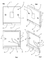
- a conventional domestic rocker lighting switch 10 including a face plate 11 and a rocker dolly 12 mounted centrally in the face plate.
- the dolly operates a switch mechanism mounted behind the face plate but that mechanism forms no part of this invention and will not be described in further detail here.
- Two fixing screws 13 extend through opposed holes to each side of the dolly 12 into threaded bores in a box mounted in a wall, behind the llight switch.
- the spacing of those holes together with the overall dimensions of the face plate 11 are standardised and all manufacturers of domestic lighting switches produce at least some switches to those dimensions.
- safety lighting assembly of this invention comprises a moulded plastics frame 15 of square shape and having two side rails 16, a top rail 17 and a bottom rail 18 which supports a housing 19.
- the external dimensions across the two side rails and across the top and bottom rails but excluding the housing 19 match the overall dimensions of the face plate 11 such that the face plate may be fitted to the frame as shown in Figure 2 .
- the housing 19 extends along the lower edge of the face plate and that housing is so dimensioned that the front wall 20 thereof is substantially co-planar with the front surface of the face plate 11.
- the two side rails 16 are provided with central bosses 20 furnished with through-bores, at the same spacing as the fixing screws 13 of the conventional light switch.
- the fixing screws will extend through the bores in the bosses 20 in order to ensure proper alignment of the frame with the face plate and also clamping of the frame between the switch and the wall.
- the front wall 21 of the housing 19 includes a translucent window 22 behind which is mounted an array of high intensity white-light LEDs each directed at a slightly different angle in order that when illuminated, a broadly divergent light beam will be obtained, giving a general spread of lighting. Also accommodated within the housing 19 is a battery holder and the end wall 23 of the housing is removable in order to allow replacement of a battery located within the holder.
- An electronic circuit is provided within the housing which circuit includes a solid-state switch for the supply of current from a held battery to the LEDs such that when the solid-state switch conducts, the LEDs are illuminated.
- the electronic circuit includes a mains supply detector which controls the solid-state switch for the LEDs; whenever no mains supply is detected, the solid-state switch biased into conduction in order to illuminate LEDs.
- a pair of flying wires 24 are connected to the electronic circuit and leave the housing at one end thereof. Those wires are intended to be connected across the terminals of the light switch operated by the dolly 12, in order to allow the detection of a mains supply at the light switch, by the electronic circuit.
- the top rail 17 is provided with a split 25, so allowing the rail to be sprung open and wires extending to the switch to be passed into the central region of the frame.
- the ends of the top rail at the split 25 may be shaped to clip together, so as to hold the frame in the required shape during clamping of the frame between the switch and the wall.
- the illumination of the LEDs behind the window 22 is inhibited. Should the mains supply fail, this is detected and the solid state switch is biased into its conducting mode such that the LEDs are illuminated. Though the potential difference between the terminals of the switch is relatively small when the mains supply is present and the light switch is closed, nevertheless there is still a sufficient potential there to allow detection of the mains supply and inhibit illumination of the LEDs, so long as the light switch has properly been installed on the live conductor of the mains supply, as required by the wiring regulations, and the load side of the switch has been connected to the light controlled by the switch.
Landscapes
- Engineering & Computer Science (AREA)
- General Engineering & Computer Science (AREA)
- Arrangement Of Elements, Cooling, Sealing, Or The Like Of Lighting Devices (AREA)
Applications Claiming Priority (1)
| Application Number | Priority Date | Filing Date | Title |
|---|---|---|---|
| GBGB0813973.5A GB0813973D0 (en) | 2008-07-31 | 2008-07-31 | Saftey lighting |
Publications (1)
| Publication Number | Publication Date |
|---|---|
| EP2149744A1 true EP2149744A1 (fr) | 2010-02-03 |
Family
ID=39767253
Family Applications (1)
| Application Number | Title | Priority Date | Filing Date |
|---|---|---|---|
| EP09166384A Withdrawn EP2149744A1 (fr) | 2008-07-31 | 2009-07-24 | Éclairage de sécurité |
Country Status (2)
| Country | Link |
|---|---|
| EP (1) | EP2149744A1 (fr) |
| GB (1) | GB0813973D0 (fr) |
Cited By (7)
| Publication number | Priority date | Publication date | Assignee | Title |
|---|---|---|---|---|
| GB2494896A (en) * | 2011-09-22 | 2013-03-27 | Thomas Mason | Device for retaining and charging rechargeable batteries incorporated into a pattress or wall/junction box. |
| CN103883965A (zh) * | 2014-03-20 | 2014-06-25 | 宁波育利电器有限公司 | 一种红外感应灯 |
| US10139790B2 (en) | 2015-06-10 | 2018-11-27 | Vivint, Inc. | Powered faceplate integration |
| US10704776B2 (en) | 2017-11-17 | 2020-07-07 | Promier Products Inc. | Sliding light switch with integrated light source |
| USD904319S1 (en) | 2018-11-16 | 2020-12-08 | Promier Products Inc. | Light switch with sliding actuator and integrated light source |
| US11394157B2 (en) | 2011-08-01 | 2022-07-19 | Snaprays, Llc | Active cover plates |
| US11888301B2 (en) | 2011-08-01 | 2024-01-30 | Snaprays, Llc | Active cover plates |
Citations (7)
| Publication number | Priority date | Publication date | Assignee | Title |
|---|---|---|---|---|
| US4611264A (en) * | 1983-05-04 | 1986-09-09 | Bradley Morgan B | Combination switch light and rechargeable flashlight |
| US4631649A (en) * | 1985-10-16 | 1986-12-23 | Chloride Systems, a division of Chloride Power Electronics, Incorporated | Plug-in emergency light fixture |
| US5713655A (en) * | 1995-01-23 | 1998-02-03 | Blackman; Stephen E. | Emergency safety light |
| US6010228A (en) * | 1997-11-13 | 2000-01-04 | Stephen E. Blackman | Wireless emergency safety light with sensing means for conventional light switch or plug receptacle |
| WO2001061244A1 (fr) * | 1996-05-02 | 2001-08-23 | Rintz William J | Couvercle d'interrupteur de lumiere |
| US6648496B1 (en) * | 2000-06-27 | 2003-11-18 | General Electric Company | Nightlight with light emitting diode source |
| US6805469B1 (en) * | 2003-05-03 | 2004-10-19 | R A Barton | Concealed safety lighting device |
-
2008
- 2008-07-31 GB GBGB0813973.5A patent/GB0813973D0/en not_active Ceased
-
2009
- 2009-07-24 EP EP09166384A patent/EP2149744A1/fr not_active Withdrawn
Patent Citations (7)
| Publication number | Priority date | Publication date | Assignee | Title |
|---|---|---|---|---|
| US4611264A (en) * | 1983-05-04 | 1986-09-09 | Bradley Morgan B | Combination switch light and rechargeable flashlight |
| US4631649A (en) * | 1985-10-16 | 1986-12-23 | Chloride Systems, a division of Chloride Power Electronics, Incorporated | Plug-in emergency light fixture |
| US5713655A (en) * | 1995-01-23 | 1998-02-03 | Blackman; Stephen E. | Emergency safety light |
| WO2001061244A1 (fr) * | 1996-05-02 | 2001-08-23 | Rintz William J | Couvercle d'interrupteur de lumiere |
| US6010228A (en) * | 1997-11-13 | 2000-01-04 | Stephen E. Blackman | Wireless emergency safety light with sensing means for conventional light switch or plug receptacle |
| US6648496B1 (en) * | 2000-06-27 | 2003-11-18 | General Electric Company | Nightlight with light emitting diode source |
| US6805469B1 (en) * | 2003-05-03 | 2004-10-19 | R A Barton | Concealed safety lighting device |
Cited By (9)
| Publication number | Priority date | Publication date | Assignee | Title |
|---|---|---|---|---|
| US11394157B2 (en) | 2011-08-01 | 2022-07-19 | Snaprays, Llc | Active cover plates |
| US11888301B2 (en) | 2011-08-01 | 2024-01-30 | Snaprays, Llc | Active cover plates |
| GB2494896A (en) * | 2011-09-22 | 2013-03-27 | Thomas Mason | Device for retaining and charging rechargeable batteries incorporated into a pattress or wall/junction box. |
| CN103883965A (zh) * | 2014-03-20 | 2014-06-25 | 宁波育利电器有限公司 | 一种红外感应灯 |
| US10139790B2 (en) | 2015-06-10 | 2018-11-27 | Vivint, Inc. | Powered faceplate integration |
| US10591881B1 (en) | 2015-06-10 | 2020-03-17 | Vivint, Inc. | Powered faceplate integration |
| US10704776B2 (en) | 2017-11-17 | 2020-07-07 | Promier Products Inc. | Sliding light switch with integrated light source |
| USD904319S1 (en) | 2018-11-16 | 2020-12-08 | Promier Products Inc. | Light switch with sliding actuator and integrated light source |
| USD937790S1 (en) | 2018-11-16 | 2021-12-07 | Promier Products Inc. | Light switch with sliding actuator and integrated light source |
Also Published As
| Publication number | Publication date |
|---|---|
| GB0813973D0 (en) | 2008-09-10 |
Similar Documents
| Publication | Publication Date | Title |
|---|---|---|
| EP2149744A1 (fr) | Éclairage de sécurité | |
| US9759391B1 (en) | LED light fixture assembly | |
| US7990252B2 (en) | Safety system and method for conventional lighting fixtures | |
| US7520072B2 (en) | Exit signs with and without emergency lighting | |
| CA2047830C (fr) | Indicateur de sortie avec generatrice de secours amovible | |
| KR100810499B1 (ko) | 전구용 소켓에 설치되는 비상등 | |
| US5055986A (en) | Combination light, radio and clock | |
| US20090180271A1 (en) | Nightlight Flashlight | |
| CA2620185C (fr) | Systeme et dispositif d'eclairage d'urgence | |
| JP2009272135A (ja) | 照明器具 | |
| GB2462146A (en) | Mains power failure emergency lighting | |
| WO2016133493A1 (fr) | Ensemble chemin lumineux encastré/appareil d'éclairage à del | |
| JP6817578B2 (ja) | 非常用照明器具 | |
| KR200449261Y1 (ko) | 비상구 유도등 | |
| WO2010139385A2 (fr) | Indicateur de défaillance du courant secteur | |
| JP6631919B2 (ja) | 光源ユニット及び照明器具 | |
| GB2255242A (en) | Emergency lighting system | |
| JP2010040205A (ja) | 照明装置 | |
| CN105444094A (zh) | Led平板灯 | |
| JP3845881B2 (ja) | フットライト | |
| WO2009103386A1 (fr) | Ensemble douille d’éclairage de sécurité | |
| US20030192216A1 (en) | Escape guiding or indicating device | |
| CN209856945U (zh) | 一种led应急筒灯 | |
| JP2008186678A (ja) | 防災用照明装置 | |
| JP7190678B2 (ja) | 防災照明装置 |
Legal Events
| Date | Code | Title | Description |
|---|---|---|---|
| PUAI | Public reference made under article 153(3) epc to a published international application that has entered the european phase |
Free format text: ORIGINAL CODE: 0009012 |
|
| AK | Designated contracting states |
Kind code of ref document: A1 Designated state(s): AT BE BG CH CY CZ DE DK EE ES FI FR GB GR HR HU IE IS IT LI LT LU LV MC MK MT NL NO PL PT RO SE SI SK SM TR |
|
| AX | Request for extension of the european patent |
Extension state: AL BA RS |
|
| STAA | Information on the status of an ep patent application or granted ep patent |
Free format text: STATUS: THE APPLICATION IS DEEMED TO BE WITHDRAWN |
|
| 18D | Application deemed to be withdrawn |
Effective date: 20100804 |