EP2149702B1 - Rotor shaft bearing of a wind turbine - Google Patents
Rotor shaft bearing of a wind turbine Download PDFInfo
- Publication number
- EP2149702B1 EP2149702B1 EP09008904.6A EP09008904A EP2149702B1 EP 2149702 B1 EP2149702 B1 EP 2149702B1 EP 09008904 A EP09008904 A EP 09008904A EP 2149702 B1 EP2149702 B1 EP 2149702B1
- Authority
- EP
- European Patent Office
- Prior art keywords
- bearing
- rotor
- wind turbine
- sleeve
- turbine according
- Prior art date
- Legal status (The legal status is an assumption and is not a legal conclusion. Google has not performed a legal analysis and makes no representation as to the accuracy of the status listed.)
- Not-in-force
Links
Images


Classifications
-
- F—MECHANICAL ENGINEERING; LIGHTING; HEATING; WEAPONS; BLASTING
- F16—ENGINEERING ELEMENTS AND UNITS; GENERAL MEASURES FOR PRODUCING AND MAINTAINING EFFECTIVE FUNCTIONING OF MACHINES OR INSTALLATIONS; THERMAL INSULATION IN GENERAL
- F16C—SHAFTS; FLEXIBLE SHAFTS; ELEMENTS OR CRANKSHAFT MECHANISMS; ROTARY BODIES OTHER THAN GEARING ELEMENTS; BEARINGS
- F16C19/00—Bearings with rolling contact, for exclusively rotary movement
- F16C19/54—Systems consisting of a plurality of bearings with rolling friction
- F16C19/546—Systems with spaced apart rolling bearings including at least one angular contact bearing
- F16C19/547—Systems with spaced apart rolling bearings including at least one angular contact bearing with two angular contact rolling bearings
- F16C19/548—Systems with spaced apart rolling bearings including at least one angular contact bearing with two angular contact rolling bearings in O-arrangement
-
- F—MECHANICAL ENGINEERING; LIGHTING; HEATING; WEAPONS; BLASTING
- F03—MACHINES OR ENGINES FOR LIQUIDS; WIND, SPRING, OR WEIGHT MOTORS; PRODUCING MECHANICAL POWER OR A REACTIVE PROPULSIVE THRUST, NOT OTHERWISE PROVIDED FOR
- F03D—WIND MOTORS
- F03D80/00—Details, components or accessories not provided for in groups F03D1/00 - F03D17/00
- F03D80/70—Bearing or lubricating arrangements
-
- F—MECHANICAL ENGINEERING; LIGHTING; HEATING; WEAPONS; BLASTING
- F16—ENGINEERING ELEMENTS AND UNITS; GENERAL MEASURES FOR PRODUCING AND MAINTAINING EFFECTIVE FUNCTIONING OF MACHINES OR INSTALLATIONS; THERMAL INSULATION IN GENERAL
- F16C—SHAFTS; FLEXIBLE SHAFTS; ELEMENTS OR CRANKSHAFT MECHANISMS; ROTARY BODIES OTHER THAN GEARING ELEMENTS; BEARINGS
- F16C19/00—Bearings with rolling contact, for exclusively rotary movement
- F16C19/22—Bearings with rolling contact, for exclusively rotary movement with bearing rollers essentially of the same size in one or more circular rows, e.g. needle bearings
- F16C19/34—Bearings with rolling contact, for exclusively rotary movement with bearing rollers essentially of the same size in one or more circular rows, e.g. needle bearings for both radial and axial load
- F16C19/36—Bearings with rolling contact, for exclusively rotary movement with bearing rollers essentially of the same size in one or more circular rows, e.g. needle bearings for both radial and axial load with a single row of rollers
- F16C19/364—Bearings with rolling contact, for exclusively rotary movement with bearing rollers essentially of the same size in one or more circular rows, e.g. needle bearings for both radial and axial load with a single row of rollers with tapered rollers, i.e. rollers having essentially the shape of a truncated cone
-
- F—MECHANICAL ENGINEERING; LIGHTING; HEATING; WEAPONS; BLASTING
- F16—ENGINEERING ELEMENTS AND UNITS; GENERAL MEASURES FOR PRODUCING AND MAINTAINING EFFECTIVE FUNCTIONING OF MACHINES OR INSTALLATIONS; THERMAL INSULATION IN GENERAL
- F16C—SHAFTS; FLEXIBLE SHAFTS; ELEMENTS OR CRANKSHAFT MECHANISMS; ROTARY BODIES OTHER THAN GEARING ELEMENTS; BEARINGS
- F16C35/00—Rigid support of bearing units; Housings, e.g. caps, covers
- F16C35/04—Rigid support of bearing units; Housings, e.g. caps, covers in the case of ball or roller bearings
- F16C35/06—Mounting or dismounting of ball or roller bearings; Fixing them onto shaft or in housing
-
- F—MECHANICAL ENGINEERING; LIGHTING; HEATING; WEAPONS; BLASTING
- F05—INDEXING SCHEMES RELATING TO ENGINES OR PUMPS IN VARIOUS SUBCLASSES OF CLASSES F01-F04
- F05B—INDEXING SCHEME RELATING TO WIND, SPRING, WEIGHT, INERTIA OR LIKE MOTORS, TO MACHINES OR ENGINES FOR LIQUIDS COVERED BY SUBCLASSES F03B, F03D AND F03G
- F05B2240/00—Components
- F05B2240/50—Bearings
-
- F—MECHANICAL ENGINEERING; LIGHTING; HEATING; WEAPONS; BLASTING
- F16—ENGINEERING ELEMENTS AND UNITS; GENERAL MEASURES FOR PRODUCING AND MAINTAINING EFFECTIVE FUNCTIONING OF MACHINES OR INSTALLATIONS; THERMAL INSULATION IN GENERAL
- F16C—SHAFTS; FLEXIBLE SHAFTS; ELEMENTS OR CRANKSHAFT MECHANISMS; ROTARY BODIES OTHER THAN GEARING ELEMENTS; BEARINGS
- F16C2229/00—Setting preload
-
- F—MECHANICAL ENGINEERING; LIGHTING; HEATING; WEAPONS; BLASTING
- F16—ENGINEERING ELEMENTS AND UNITS; GENERAL MEASURES FOR PRODUCING AND MAINTAINING EFFECTIVE FUNCTIONING OF MACHINES OR INSTALLATIONS; THERMAL INSULATION IN GENERAL
- F16C—SHAFTS; FLEXIBLE SHAFTS; ELEMENTS OR CRANKSHAFT MECHANISMS; ROTARY BODIES OTHER THAN GEARING ELEMENTS; BEARINGS
- F16C2360/00—Engines or pumps
- F16C2360/31—Wind motors
-
- Y—GENERAL TAGGING OF NEW TECHNOLOGICAL DEVELOPMENTS; GENERAL TAGGING OF CROSS-SECTIONAL TECHNOLOGIES SPANNING OVER SEVERAL SECTIONS OF THE IPC; TECHNICAL SUBJECTS COVERED BY FORMER USPC CROSS-REFERENCE ART COLLECTIONS [XRACs] AND DIGESTS
- Y02—TECHNOLOGIES OR APPLICATIONS FOR MITIGATION OR ADAPTATION AGAINST CLIMATE CHANGE
- Y02E—REDUCTION OF GREENHOUSE GAS [GHG] EMISSIONS, RELATED TO ENERGY GENERATION, TRANSMISSION OR DISTRIBUTION
- Y02E10/00—Energy generation through renewable energy sources
- Y02E10/70—Wind energy
- Y02E10/72—Wind turbines with rotation axis in wind direction
Definitions
- the present invention relates to a wind energy plant with a rotor which is connected via a rotor shaft with a gear or a generator.
- the rotor shaft is mounted via two tapered roller bearings in O arrangement preferably via a bearing housing on a carrier unit of the wind turbine.
- Each of the two tapered roller bearings has an inner ring and an outer ring.
- Out DE 103 51 524 is known a rotor bearing for a wind turbine.
- the rotor bearing is used to transmit Rotorbiege- and -windmomenten, with two tapered roller bearings are provided with housing-fixed outer ring and a downstream planetary gear.
- the illustrated tapered roller bearings are designed as a tapered roller bearing pair, which has an integrally formed outer ring.
- the rolling elements of the tapered roller bearing pair are arranged so that the rotor-side rolling element with a perpendicular to its axis of rotation normal direction of the bearing assembly intersects the axis of rotation of the rotor, while the gear-side rolling element with its perpendicular to its axis of rotation normal direction of the transmission side intersects the axis of rotation of the rotor.
- tapered roller bearings with rotating inner ring are referred to in technical language as a tapered roller bearing in O arrangement.
- the use of the tapered roller bearing in O arrangement with an integrally formed outer ring allows a very compact design for the rotor bearing.
- Out DE 103 92 908 B4 is a wind turbine with a tapered roller bearing assembly is known in which the bearing assembly has a first relative to the rotor axis rotationally fixed to a carrier unit and a second rotatable relative to the rotor axis bearing ring.
- the bearing has three rows of cylindrical bodies, with a row at the front and one row each side of the inner ring.
- WO 2006/000214 A1 is a drive train storage for a wind turbine known, in which a tapered roller bearing pair with split inner ring and integrally formed outer ring is provided.
- a bearing arrangement for a pinion shaft in a transmission is known.
- a bearing assembly for a pinion shaft is proposed, which shows two tapered roller bearings in O arrangement, wherein the pinion shaft is additionally mounted on a cylindrical roller bearing in the transmission housing.
- Figure 37 shows a bearing for a rotor shaft of a wind turbine with two tapered roller bearings in O arrangement, whereby the outer ring is formed in one piece.
- WO 2007/085644 A1 a storage of the rotor shaft for a wind turbine is known, wherein a trained in the manner of a moment bearing second rotor bearing is provided as a set against each other tapered roller bearing pair in O arrangement.
- the bearing clearance of the tapered roller bearings is set via a gearbox-side pin connection.
- Out DE 102 31 948 A1 is a wind turbine with a bearing assembly is known in which a first rotatably fixed to the rotor axis to a support assembly bearing ring cooperates with a second rotatable to the rotor axis and fixed to the rotor hub bearing ring.
- the bearing rings have a front side and two laterally arranged rolling elements.
- Out JP 2007 162 750 a bearing assembly for a wind turbine has become known, in which two tapered roller bearings are mounted in O arrangement on a carrier unit.
- the Tapered roller bearings have an inner ring and an outer ring, wherein the inner rings are fixed to each other via a sleeve in their distance in the axial direction, relative to the longitudinal axis of the rotor shaft.
- the invention has for its object to provide a wind turbine with a bearing assembly for the rotor shaft, which allows the simplest possible adjustment and installation of the bearing.
- the wind turbine according to the invention has a rotor which is connected via a rotor shaft with a gear and a generator.
- the rotor shaft is mounted directly or indirectly via two tapered roller bearings in O arrangement on a carrier unit.
- a separate inner ring and a separate outer ring are provided in each case for each tapered roller bearing.
- the inner rings and the outer rings of the tapered roller bearings are fixed to one another via an adjusting device in their distance in the axial direction relative to the rotor shaft.
- two tapered roller bearings each having a separate inner and outer ring are used, which are spaced apart from one another.
- the setting of the distance between the two tapered roller bearings takes place in an axial direction, wherein the axial direction refers to the rotor shaft or its axis of rotation.
- the adjusting device makes it possible, the tapered roller bearings already in the manufacture prior to assembly on the rotor shaft on the invention set adjustment to the desired level. As a result, the assembly on the rotor shaft is significantly simplified.
- the adjusting device comprises two sleeves, of which a first is arranged between the inner rings and a second between the outer rings of the tapered roller bearings.
- the adjustment device with two sleeves ensures that the distance between the inner rings and between the outer rings, which is necessary for the bearing via the tapered roller bearings, is guaranteed. It is possible that the first sleeve has a different length from the second sleeve.
- the outer rings of the tapered roller bearings each have on their sides facing each other a shoulder or a recess, for example in the form of a groove for receiving an end face of the second sleeve.
- a shoulder or a recess for example in the form of a groove for receiving an end face of the second sleeve.
- groove may be present.
- the inner rings of the tapered roller bearings each have a shoulder or a recess for receiving the first sleeve on their mutually facing sides. This allows, as well as the heels in the outer rings to bring the sleeves in a defined position.
- the sleeves can hereby obtain a smaller (larger) diameter than the bearing seats in the bearing housing (on the rotor shaft), damage to the bearing seats during assembly of the sleeves is avoided.
- the rotor shaft has means for fixing one or both tapered roller bearings on the rotor shaft.
- a shoulder may be provided on the shaft, which serves as an abutment, for example, for the inner ring of the rotor-side tapered roller bearing.
- the inner ring of the rotor-side tapered roller bearing is in this case on its side facing the rotor to the shoulder on the rotor shaft.
- the position of the rotor-side tapered roller bearing on the rotor side Are defined.
- the outer rings of the tapered roller bearings are connected via a bearing housing with the carrier unit.
- the bearing housing is integrally formed and surrounds the outer rings of the tapered roller bearings.
- a respective bearing cap is provided on the rotor side and / or on the transmission side, which is connected to the bearing housing, preferably screwed, is.
- the shoulder on the bearing housing serves, as already the shoulder on the rotor shaft, to set the position of the outer ring of the respective tapered roller bearing in the axial direction on one side.
- the shoulder on the bearing housing may alternatively be replaced by an inserted into the bearing housing spacer sleeve or other means for fixing the outer ring in the axial direction.
- the inner ring of the transmission-side tapered roller bearing is fixed on its side facing the transmission via a shaft nut or other device for applying an axial biasing force in the axial direction.
- the rotor shaft is screwed on the transmission side with a gear flange for connecting the rotor shaft with an input shaft of the transmission.
- the torque is transferred from the rotor via the rotor shaft via the gearbox flange to the downstream gearbox.
- a rotor locking disk is arranged on the transmission side of the rotor shaft, the rotor locking disk abutting the inner ring of the transmission-side tapered-roller bearing directly or indirectly on the transmission side.
- the rotor lock washer has a bore for receiving a locking bolt integrated on the bearing housing.
- the rotor can be fixed in a defined position. Such setting of the rotor is desirable, for example, for assembly and maintenance purposes.
- the rotor locking disk on means for axial bearing fixation, which consist for example of a threaded bore in the Rotorarretiersay and a corresponding pressure screw.
- the pressure screw is located on the transmission side by the threaded bore on the inner ring of the transmission-side tapered roller bearing.
- a force is exerted on the inner ring of the transmission-side tapered roller bearing in the axial direction.
- the tapered roller bearing pair is also adjusted via the pressure screw.
- the locking disk simultaneously serves as means for transmitting the torque from the rotor shaft to the transmission.
- FIGS. 5 and 5a show a rotor shaft bearing according to the invention, the FIGS. 1 to 4 . 4a serve for a more detailed explanation.
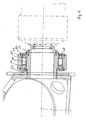
- FIG. 1 shows a section of a rotor hub 10 which is connected via a locking disc 12 with a rotor shaft 14, wherein the locking disc is clamped between the rotor shaft and rotor hub.
- the connection is made by means of screws (not shown) in threaded bores 16 which extend on the rotor side through the rotor hub 10 and the locking disk 12 into the rotor shaft 14.
- a gear flange 18 is also screwed on the front side of the rotor shaft 14 via screws 20 (not shown).
- the tapered roller bearing 24 is the rotor-side tapered roller bearing, wherein the tapered roller bearing 26 is considered as the transmission-side tapered roller bearing.
- the inner rings 28, 30 are arranged offset in the axial direction of the rotor shaft relative to the outer rings 32, 34.
- the inner ring 28 of the rotor-side tapered roller bearing is offset in the direction of the rotor relative to the outer ring 32.
- the inner ring 30 of the gear-side tapered roller bearing 26 is offset from the gear towards the outer ring 34 of the transmission-side tapered roller bearing.
- a first sleeve 36 is inserted between the inner rings 28 and 30 of the tapered roller bearings 24 and 26, a first sleeve 36 is inserted.
- the first sleeve 36 abuts against the rotor shaft 14, wherein the sleeve can rest completely or in sections on the rotor shaft.
- the sleeve 36 defines the distance between the inner rings 28 and 30.
- a second sleeve 38 is arranged.
- the sleeves 36 and 38 have a different length, wherein the difference in length between these sleeves is set so that the inner ring and outer ring occupy the defined position to each other.
- the sleeves 36 and 38 are cut to size accurate to about 1/100 mm.
- the outer rings 32, 34 are of a bearing housing 40 (see. Fig. 1 enclosed below).
- the bearing housing 40 has in the in FIG. 1 illustrated embodiment, an inner surface against which the outer sides of the outer rings 32, 34.
- the second sleeve 38 may rest on the inner surface or, alternatively, abut in sections on the inner surface of the bearing housing.
- an axial bore 42 is provided in the bearing housing, in which via a screw (not shown), a rotor-side bearing cap 44 is screwed.
- the bearing housing 40 is also provided with a bore 48 through which a bearing cap 46 is bolted to the bearing housing 40 (screws not shown).
- the bearing caps 44, 46 have on their facing the tapered roller bearings inside each one projecting in the axial direction of the shoulder, which bears against the outer rings of the tapered roller bearings.
- a shaft nut 50 on a threaded portion 51 provided on the gear-side end of the rotor shaft 14 serves to clamp the bearing inner rings and the first sleeve 36 in a defined manner.
- the detailed view of Figure 1a shows the shaft nut 50 from the upper portion of FIG. 1 .
- the process of applying a defined preload force is referred to as: Pull the inner rings and the sleeve to block.
- a shaft sleeve 55 is provided, which transmits the biasing force of the shaft nut 50.
- the rotor-side tapered roller bearing is positioned with the rotor side down. Subsequently, the outer sleeve 38 is placed. The gear-side tapered roller bearing is subsequently placed on the outer sleeve. To set the bearing of the transmission side bearing inner ring is then loaded with a defined axial force and measured the distance between the two bearing inner rings. Based on the measured distance, the inner sleeve 36 is manufactured with the required excess for adjustment with bearing clearance or undersize for adjustment with bias. Due to the exact manufacture of the inner sleeve, the tapered roller bearings are adjusted to each other after application of an axial force.
- FIG. 1 has the rotor shaft 14 at its end facing the rotor 10, a shoulder 52 on which the inner ring 28 of the rotor-side tapered roller bearing 24 is applied to the transmission side. Via the shoulder 52 on the rotor shaft 14 in cooperation with the first sleeve 36, the shaft sleeve 55 and the shaft nut 50, the position of the inner rings 28 and 30 is fixed on the rotor shaft 14.
- FIG. 2 shows an alternative embodiment of the storage. Subsequently, the same components are provided with the same reference numerals.
- the inner ring of the rotor-side tapered roller bearing 24 is again on the transmission side to a shoulder 52 of the rotor shaft 14 at.
- the bearing housing 41 has a shoulder 53 on the transmission side, on which the outer ring of the gear-side tapered roller bearing 26 rests on the rotor side. In this way, the position of the outer ring of the transmission-side bearing is additionally determined.
- the transmission-side bearing cap 47 is not applied to the outer ring 34, but is spaced therefrom in the axial direction.
- the assembly can be adjusted to the rotor shaft 14 by the sleeves 36 and 38 are previously matched precisely to each other, so that the inner rings and the outer rings have the intended distance from each other.
- FIG. 3 shows a further embodiment of the rotor bearing.
- the bearing housing 40 in the third embodiment has different design than the embodiment FIG. 2 no shoulder at the rotor end. Rather, the outer rings 34 and 32 of the tapered roller bearings abut on a portion of the inner surface of the bearing housing 40.
- the area of the inner surface of the bearing housing between the outer rings 32 and 34 may in this case have a depression, as well as the area on the rotor shaft 14 between the inner rings 28, 30.
- FIG. 3a shown Here, a spacer sleeve 60 is placed on the rotor shaft 14.
- the spacer sleeve 60 can be fixed axially on the rotor side by the locking disk 12, the rotor hub directly or another rotating component in the rotor-side direction. On the transmission side, the spacer sleeve 60 supports the inner ring 28 of the rotor-side tapered roller bearing. The spacer sleeve 60 thus performs the same task as the shoulder 52 according to the embodiments FIGS. 1 and 2 and also avoids that the rotor shaft 17 receives a larger diameter in the form of a shaft shoulder and thus a jump in stiffness.
- FIGS. 4 and 4a show a further example of storage, in which again the same components are provided with the same reference numerals.
- the tapered roller bearings 24 and 26 are arranged on the rotor-side or gear-side end of the rotor shaft 14.
- the rotor-side tapered roller bearing 24 rests with its inner ring 28 on the rotor side on a shaft shoulder 52.
- the gear-side tapered roller bearing 26 is located with his
- the outer rings 32 and 34 of the tapered roller bearings are arranged within the bearing housing 40. Between the outer rings 32 and 34, the sleeve 38 is arranged, which also bears against the bearing housing 40.
- a rotor locking unit 64 is provided, which has a locking pin 66, by means of which the rotor shaft and the rotor can be fixed relative to the rotor locking disk 62. For this purpose, the bolt 66 is advanced so that it engages in a bore 68 in the rotor locking disk 62.
- the Rotorarretiersay 62 has a threaded bore 70 through which a pressure screw (not shown) can be screwed to apply a defined force on the inner ring 30 of the gear-side tapered roller bearing 26 and to fix this simultaneously in its axial position.
- a pressure screw (not shown) can be screwed to apply a defined force on the inner ring 30 of the gear-side tapered roller bearing 26 and to fix this simultaneously in its axial position.
- FIGS. 5 and 5a show an embodiment of the storage according to the invention, in which the inside of the outer rings 32 and 34 are each provided with a shoulder 72.
- the second sleeve 38 rests between the outer rings 32 and 34 in the paragraphs 72, respectively.
- the inner rings 28, 30 of the tapered roller bearings are provided with shoulders 74 against which the first sleeve 36 rests.
- paragraphs 72, 74 enclose the sleeves 36, 38 relative to the pair of bearings outside or otherwise shaped recesses for receiving the sleeves 36, 38 may be provided if they adapted to the geometry of the sleeves.
Abstract
Description
Die vorliegende Erfindung betrifft eine Windenergieanlage mit einem Rotor, der über eine Rotorwelle mit einem Getriebe oder einem Generator verbunden ist. Die Rotorwelle ist über zwei Kegelrollenlager in O-Anordnung vorzugsweise über ein Lagergehäuse an einer Trägereinheit der Windenergieanlage gelagert. Jedes der beiden Kegelrollenlager weist einen Innen- und einen Außenring auf.The present invention relates to a wind energy plant with a rotor which is connected via a rotor shaft with a gear or a generator. The rotor shaft is mounted via two tapered roller bearings in O arrangement preferably via a bearing housing on a carrier unit of the wind turbine. Each of the two tapered roller bearings has an inner ring and an outer ring.
Aus
Aus
Aus
Aus
Aus dem Dokument
Aus
Aus
Aus
Der Erfindung liegt die Aufgabe zugrunde, eine Windenergieanlage mit einer Lageranordnung für die Rotorwelle bereitzustellen, die eine möglichst einfache Einstellung und Montage des Lagers zulässt.The invention has for its object to provide a wind turbine with a bearing assembly for the rotor shaft, which allows the simplest possible adjustment and installation of the bearing.
Erfindungsgemäß wird die Aufgabe durch eine Windenergieanlage gemäß Anspruch 1 und gemäß Anspruch 8 gelöst. Vorteilhafte Ausgestaltungen bilden die Gegenstände der Unteransprüche.According to the invention the object is achieved by a wind energy plant according to claim 1 and according to claim 8. Advantageous embodiments form the subject of the dependent claims.
Die erfindungsgemäße Windenergieanlage besitzt einen Rotor, der über eine Rotorwelle mit einem Getriebe und einem Generator verbunden ist. Die Rotorwelle ist über zwei Kegelrollenlager in O-Anordnung an einer Trägereinheit mittelbar oder unmittelbar gelagert. Bei den erfindungsgemäß ausgestalteten Kegelrollenlagern ist jeweils für jedes Kegelrollenlager ein separater Innenring und ein separater Außenring vorgesehen. Erfindungsgemäß sind die Innenringe und die Außenringe der Kegelrollenlager über eine Einstelleinrichtung in ihrem Abstand in axialer Richtung bezogen auf die Rotorwelle zueinander festgelegt. Anders als in der aus dem Stand der Technik bekannten Lösung werden bei der erfindungsgemäßen Lösung zwei Kegelrollenlager mit jeweils separatem Innen- und Außenring eingesetzt, die voneinander beabstandet sind. Das Einstellen des Abstands der beiden Kegelrollenlager erfolgt in einer axialen Richtung, wobei sich die axiale Richtung auf die Rotorwelle bzw. deren Rotationsachse bezieht. Durch die Einstelleinrichtung zwischen den Kegelrollenlagern ist es möglich, diese definiert voneinander zu beabstanden und damit gezielt die Lagervorspannung oder Lagerluft einzustellen, wodurch eine gleichmäßigere Belastung der Lagerlaufbahn erfolgt. Gleichzeitig macht die Einstelleinrichtung es möglich, die Kegelrollenlager bereits bei der Herstellung vor der Montage auf die Rotorwelle über die erfindungsgemäß vorgesehene Einstelleinrichtung auf das gewünschte Maß einzustellen. Hierdurch wird die Montage auf die Rotorwelle deutlich vereinfacht.The wind turbine according to the invention has a rotor which is connected via a rotor shaft with a gear and a generator. The rotor shaft is mounted directly or indirectly via two tapered roller bearings in O arrangement on a carrier unit. In the tapered roller bearings designed according to the invention, a separate inner ring and a separate outer ring are provided in each case for each tapered roller bearing. According to the invention, the inner rings and the outer rings of the tapered roller bearings are fixed to one another via an adjusting device in their distance in the axial direction relative to the rotor shaft. Unlike in the solution known from the prior art, in the solution according to the invention two tapered roller bearings each having a separate inner and outer ring are used, which are spaced apart from one another. The setting of the distance between the two tapered roller bearings takes place in an axial direction, wherein the axial direction refers to the rotor shaft or its axis of rotation. By the adjustment between the tapered roller bearings, it is possible to define these defined from each other and thus selectively adjust the bearing preload or bearing clearance, whereby a more uniform load on the bearing raceway takes place. At the same time, the adjusting device makes it possible, the tapered roller bearings already in the manufacture prior to assembly on the rotor shaft on the invention set adjustment to the desired level. As a result, the assembly on the rotor shaft is significantly simplified.
Erfindungsgemäß weist die Einstelleinrichtung zwei Hülsen auf, von denen eine erste zwischen den Innenringen und eine zweite zwischen den Außenringen der Kegelrollenlager angeordnet ist. Die Einstelleinrichtung mit zwei Hülsen stellt sicher, dass der für die Lagerung über die Kegelrollenlager notwendige Abstand sowohl zwischen den Innenringen als auch zwischen den Außenringen gewährleistet wird. Dabei ist es möglich, dass die erste Hülse eine von der zweiten Hülse verschiedene Länge aufweist.According to the invention, the adjusting device comprises two sleeves, of which a first is arranged between the inner rings and a second between the outer rings of the tapered roller bearings. The adjustment device with two sleeves ensures that the distance between the inner rings and between the outer rings, which is necessary for the bearing via the tapered roller bearings, is guaranteed. It is possible that the first sleeve has a different length from the second sleeve.
Erfindungsgemäß besitzen die Außenringe der Kegelrollenlager auf ihren einander zugewandten Seiten jeweils einen Absatz oder eine Aussparung zum Beispiel in Form einer Nut zur Aufnahme eines stirnseitigen Endes der zweiten Hülse. In einer erfindungsgemäßen Ausführungsform können auch Absatz und Nut vorhanden sein.According to the invention, the outer rings of the tapered roller bearings each have on their sides facing each other a shoulder or a recess, for example in the form of a groove for receiving an end face of the second sleeve. In one embodiment of the invention also paragraph and groove may be present.
In einer weiteren Ausgestaltung der Erfindung weisen die Innenringe der Kegelrollenlager auf ihren einander zugewandten Seiten jeweils einen Absatz oder eine Aussparung zur Aufnahme der ersten Hülse auf. Dies erlaubt, ebenso wie die Absätze in den Außenringen, die Hülsen in eine definierte Position zu bringen. Durch die Absätze in den Lageraußen- bzw. Innenringen der Kegelrollenlager erfolgt eine Zentrierung der Hülsen, so dass der Einstellprozess ebenso wie die Montage der Lager sich vereinfacht.In a further embodiment of the invention, the inner rings of the tapered roller bearings each have a shoulder or a recess for receiving the first sleeve on their mutually facing sides. This allows, as well as the heels in the outer rings to bring the sleeves in a defined position. By paragraphs in the bearing outer and inner rings of the tapered roller bearings centering of the sleeves is done so that the adjustment process as well as the mounting of the camp is simplified.
Da in einer bevorzugten Ausgestaltung der Erfindung die Hülsen hierbei einen kleineren (größeren) Durchmesser als die Lagersitze im Lagergehäuse (auf der Rotorwelle) erhalten können, wird eine Beschädigung der Lagersitze bei der Montage der Hülsen vermieden.Since, in a preferred embodiment of the invention, the sleeves can hereby obtain a smaller (larger) diameter than the bearing seats in the bearing housing (on the rotor shaft), damage to the bearing seats during assembly of the sleeves is avoided.
In einer zweckmäßigen Ausgestaltung weist die Rotorwelle Mittel zur Fixierung eines oder beider Kegelrollenlager auf der Rotorwelle auf. Als Mittel zur Fixierung kann beispielsweise eine Schulter auf der Welle vorgesehen sein, die beispielsweise für den Innenring des rotorseitigen Kegelrollenlagers als Anlage dient. Der Innenring des rotorseitigen Kegelrollenlagers liegt hierbei auf seiner zum Rotor weisenden Seite an der Schulter auf der Rotorwelle an. Hierdurch ist die Position des rotorseitigen Kegelrollenlagers rotorseitig definiert. Auch ist es möglich, als Mittel zur Fixierung eine Distanzhülse auf der Rotorwelle vorzusehen, die dann rotorseitig wiederum fixiert ist.In an expedient embodiment, the rotor shaft has means for fixing one or both tapered roller bearings on the rotor shaft. As a means for fixing, for example, a shoulder may be provided on the shaft, which serves as an abutment, for example, for the inner ring of the rotor-side tapered roller bearing. The inner ring of the rotor-side tapered roller bearing is in this case on its side facing the rotor to the shoulder on the rotor shaft. As a result, the position of the rotor-side tapered roller bearing on the rotor side Are defined. It is also possible to provide as a means for fixing a spacer sleeve on the rotor shaft, which is then in turn fixed on the rotor side.
In einer bevorzugten Ausgestaltung sind die Außenringe der Kegelrollenlager über ein Lagergehäuse mit der Trägereinheit verbunden. Das Lagergehäuse ist einstückig ausgebildet und umschließt die Außenringe der Kegelrollenlager.In a preferred embodiment, the outer rings of the tapered roller bearings are connected via a bearing housing with the carrier unit. The bearing housing is integrally formed and surrounds the outer rings of the tapered roller bearings.
In einer bevorzugten Ausgestaltung ist rotorseitig und/oder getriebeseitig jeweils ein Lagerdeckel vorgesehen, der mit dem Lagergehäuse verbunden, bevorzugt verschraubt, ist.In a preferred embodiment, a respective bearing cap is provided on the rotor side and / or on the transmission side, which is connected to the bearing housing, preferably screwed, is.
Zweckmäßigerweise weist das Lagergehäuse getriebeseitig oder rotorseitig eine Schulter auf, an der der Außenring des getriebeseitigen Kegelrollenlagers auf seiner zum Getriebe weisenden Seite anliegt bzw. der Außenring des rotorseitigen Kegelrollenlagers auf seiner zum Rotor weisenden Seite anliegt. Die Schulter an dem Lagergehäuse dient, wie bereits die Schulter an der Rotorwelle, dazu, die Position des Außenrings des jeweiligen Kegelrollenlagers in axialer Richtung einseitig festzulegen. Auch die Schulter an dem Lagergehäuse kann alternativ durch eine in das Lagergehäuse eingesetzte Distanzhülse oder andere Mittel zur Fixierung des Außenrings in axialer Richtung ersetzt werden.Conveniently, the bearing housing on the transmission side or rotor side on a shoulder on which the outer ring of the gear-side tapered roller bearing rests on its side facing the gear or the outer ring of the rotor-side tapered roller bearing rests on its side facing the rotor. The shoulder on the bearing housing serves, as already the shoulder on the rotor shaft, to set the position of the outer ring of the respective tapered roller bearing in the axial direction on one side. The shoulder on the bearing housing may alternatively be replaced by an inserted into the bearing housing spacer sleeve or other means for fixing the outer ring in the axial direction.
In einer bevorzugten Ausgestaltung ist der Innenring des getriebeseitigen Kegelrollenlagers auf seiner zum Getriebe weisenden Seite über eine Wellenmutter oder eine andere Vorrichtung zum Aufbringen einer axialen Vorspannkraft in axialer Richtung festgelegt. Durch das Anziehen der Wellenmutter wird der Innenring des getriebeseitigen Kegelrollenlagers positioniert und damit die Anordnung der beiden Kegelrollenlager insgesamt in axialer Richtung eingestellt.In a preferred embodiment, the inner ring of the transmission-side tapered roller bearing is fixed on its side facing the transmission via a shaft nut or other device for applying an axial biasing force in the axial direction. By tightening the shaft nut of the inner ring of the gear-side tapered roller bearing is positioned, and thus the arrangement of the two tapered roller bearings set in the axial direction.
In einer bevorzugten Ausgestaltung ist die Rotorwelle getriebeseitig mit einem Getriebeflansch zur Verbindung der Rotorwelle mit einer Eingangswelle des Getriebes verschraubt. Über den Getriebeflansch wird das Drehmoment aus dem Rotor über die Rotorwelle auf das nachgeordnete Getriebe übertragen.In a preferred embodiment, the rotor shaft is screwed on the transmission side with a gear flange for connecting the rotor shaft with an input shaft of the transmission. The torque is transferred from the rotor via the rotor shaft via the gearbox flange to the downstream gearbox.
In einer weiteren bevorzugten Ausgestaltung ist eine Rotorarretierscheibe getriebeseitig der Rotorwelle angeordnet, wobei die Rotorarretierscheibe an dem Innenring des getriebeseitigen Kegelrollenlagers mittelbar oder unmittelbar getriebeseitig anliegt. Bevorzugt besitzt die Rotorarretierscheibe eine Bohrung zur Aufnahme eines am Lagergehäuse integrierten Arretierbolzens. Über die Rotorarretierscheibe kann der Rotor in einer definierten Position festgesetzt werden. Ein solches Festsetzen des Rotors ist beispielsweise für Montage- und Wartungszwecke erstrebenswert.In a further preferred refinement, a rotor locking disk is arranged on the transmission side of the rotor shaft, the rotor locking disk abutting the inner ring of the transmission-side tapered-roller bearing directly or indirectly on the transmission side. Preferably, the rotor lock washer has a bore for receiving a locking bolt integrated on the bearing housing. About the Rotorarretierscheibe the rotor can be fixed in a defined position. Such setting of the rotor is desirable, for example, for assembly and maintenance purposes.
In einer bevorzugten Weiterbildung weist die Rotorarretierscheibe Mittel zur axialen Lagerfixierung auf, wobei diese beispielsweise aus einer Gewindebohrung in der Rotorarretierscheibe und einer entsprechenden Druckschraube bestehen. Die Druckschraube liegt durch die Gewindebohrung hindurch getriebeseitig an dem Innenring des getriebeseitigen Kegelrollenlagers an. Über die Druckschraube wird in axialer Richtung eine Kraft auf den Innenring des getriebeseitigen Kegelrollenlagers ausgeübt. Über die Druckschraube wird zudem das Kegelrollenlagerpaar eingestellt.In a preferred embodiment, the rotor locking disk on means for axial bearing fixation, which consist for example of a threaded bore in the Rotorarretierscheibe and a corresponding pressure screw. The pressure screw is located on the transmission side by the threaded bore on the inner ring of the transmission-side tapered roller bearing. About the pressure screw, a force is exerted on the inner ring of the transmission-side tapered roller bearing in the axial direction. The tapered roller bearing pair is also adjusted via the pressure screw.
In einer weiteren bevorzugten Ausgestaltung dient die Arretierscheibe gleichzeitig als Mittel zur Übertragung des Drehmoments von der Rotorwelle auf das Getriebe.In a further preferred embodiment, the locking disk simultaneously serves as means for transmitting the torque from the rotor shaft to the transmission.
Eine Ausgestaltung der erfindungsgemäßen Rotorwellenlagerung für eine Windenergieanlage wird nachfolgend anhand der Figuren näher beschrieben. Die
Es zeigt:
- Fig. 1
- einen Querschnitt durch eine Lagerung einer Rotorwelle mit einem rotorseitigen Anschlag auf der Rotorwelle,
- Fig. 1a
- eine Detailansicht der Wellenmutter mit einer Wellenhülse,
- Fig. 2
- einen Querschnitt durch eine zweite Lagerung der Rotorwelle einer Windenergieanlage mit einem rotorseitigen Anschlag auf der Rotorwelle und einem getriebeseitigen Anschlag am Lagergehäuse,
- Fig. 3
- einen Querschnitt durch eine dritte Lagerung der Rotorwelle einer Windenergieanlage mit einer rotorseitigen Distanzhülse auf der Rotorwelle,
- Fig. 3a
- eine Detailansicht der rotorseitigen Distanzhülse aus
Fig. 3 , - Fig. 4
- einen Querschnitt einer vierten Lagerung der Rotorwelle einer Windenergieanlage mit einer getriebeseitigen Arretierscheibe an der Rotorwelle,
- Fig. 4a
- eine Detailansicht der Arretierscheibe aus
Fig. 4 , - Fig. 5
- einen Querschnitt einer erfindungsgemäßen Lagerung der Rotorwelle einer Windenergieanlage, bei der Innenring und Außenring mit einem Absatz zur Aufnahme der inneren und äußeren Hülse versehen sind, und
- Fig. 5a
- eine Detailansicht des getriebeseitigen Kegelrollenlagers aus
Fig. 5 .
- Fig. 1
- a cross section through a bearing of a rotor shaft with a rotor-side stop on the rotor shaft,
- Fig. 1a
- a detailed view of the shaft nut with a shaft sleeve,
- Fig. 2
- a cross section through a second bearing of the rotor shaft of a wind turbine with a rotor-side stop on the rotor shaft and a gear-side stop on the bearing housing,
- Fig. 3
- a cross section through a third bearing of the rotor shaft of a wind turbine with a rotor-side spacer sleeve on the rotor shaft,
- Fig. 3a
- a detailed view of the rotor-side spacer sleeve
Fig. 3 . - Fig. 4
- a cross section of a fourth bearing of the rotor shaft of a wind turbine with a gear-side locking disc on the rotor shaft,
- Fig. 4a
- a detailed view of the locking disk
Fig. 4 . - Fig. 5
- a cross section of an inventive storage of the rotor shaft of a wind turbine, are provided in the inner ring and outer ring with a shoulder for receiving the inner and outer sleeve, and
- Fig. 5a
- a detailed view of the transmission-side tapered roller bearing
Fig. 5 ,
Auf der Rotorwelle 20 sind zwei Kegelrollenlager 24, 26 angeordnet. Das Kegelrollenlager 24 ist dabei das rotorseitige Kegelrollenlager, wobei das Kegelrollenlager 26 als das getriebeseitige Kegelrollenlager angesehen wird. Wie in
Der Innenring 30 des getriebeseitigen Kegelrollenlagers 26 ist zum Getriebe hin gegenüber dem Außenring 34 des getriebeseitigen Kegelrollenlagers versetzt.The
Zwischen den Innenringen 28 und 30 der Kegelrollenlager 24 und 26 ist eine erste Hülse 36 eingesetzt. Die erste Hülse 36 liegt an der Rotorwelle 14 an, wobei die Hülse vollständig oder abschnittsweise an der Rotorwelle anliegen kann. Die Hülse 36 definiert den Abstand zwischen den Innenringen 28 und 30. Zwischen den Außenringen 32 und 34 ist eine zweite Hülse 38 angeordnet. Wie in
Die Außenringe 32, 34 sind von einem Lagergehäuse 40 (vgl.
Rotorseitig ist in dem Lagergehäuse eine axiale Bohrung 42 vorgesehen, in die über eine Schraube (nicht dargestellt) ein rotorseitiger Lagerdeckel 44 verschraubt ist. Getriebeseitig ist das Lagergehäuse 40 ebenfalls mit einer Bohrung 48 versehen, über die ein Lagerdeckel 46 mit dem Lagergehäuse 40 verschraubt ist (Schrauben nicht dargestellt). Die Lagerdeckel 44, 46 besitzen auf ihrer zu den Kegelrollenlagern weisenden Innenseite jeweils eine in axialer Richtung vorstehende Schulter, die an den Außenringen der Kegelrollenlager anliegt.On the rotor side, an axial bore 42 is provided in the bearing housing, in which via a screw (not shown), a rotor-side bearing cap 44 is screwed. Transmission side, the bearing
Eine Wellenmutter 50 auf einem am getriebeseitigen Ende der Rotorwelle 14 vorgesehenen Gewindeabschnitt 51 dient dazu, die Lagerinnenringe und die erste Hülse 36 definiert zu verspannen. Die Detailansicht aus Figur 1a zeigt die Wellenmutter 50 aus dem oberen Abschnitt der
Zum besseren Verständnis der Wirkungsweise der Hülsen 36 und 38 sei nachfolgend der Fertigungsablauf kurz erläutert.For a better understanding of the operation of the
In einem ersten Arbeitsschritt wird das rotorseitige Kegelrollenlager mit der Rotorseite nach unten positioniert. Nachfolgend wird die äußere Hülse 38 aufgesetzt. Das getriebeseitige Kegelrollenlager wird nachfolgend auf der äußeren Hülse platziert. Zur Einstellung des Lagers wird dann der getriebeseitige Lagerinnenring mit einer definierten Axialkraft belastet und der Abstand zwischen den beiden Lagerinnenringen gemessen. Ausgehend von dem gemessenen Abstand wird die innere Hülse 36 mit dem benötigten Übermaß zur Einstellung mit Lagerluft oder Untermaß zur Einstellung mit Vorspannung gefertigt. Durch die genaue Fertigung der inneren Hülse sind die Kegelrollenlager nach Aufbringen einer Axialkraft zueinander eingestellt.In a first step, the rotor-side tapered roller bearing is positioned with the rotor side down. Subsequently, the
Bei der Lagermontage mit den Hülsen 36, 38 erfolgt zunächst eine vertikale Positionierung der Rotorwelle, auf die der Lagerinnenring mit dem Wälzkörpersatz des rotorseitigen Lagers aufgeschoben wird. Nachfolgend wird die Hülse 36 eingesetzt. Anschließend erfolgt die vertikale Positionierung des Lagergehäuses und der Außenring des rotorseitigen Lagers wird eingeschoben. Es wird die äußere Hülse 38 eingesetzt und der Lageraußenring des getriebeseitigen Lagers eingeschoben. Nachfolgend wird das Lagergehäuse auf die Rotorwelle aufgesetzt und der getriebeseitige Lagerinnenring einschließlich Wälzkörpersatz auf die Rotorwelle aufgeschoben. Nachfolgend wird die getriebeseitige Wellenhülse aufgesetzt und durch ein definiertes Anziehen der Wellenmutter bzw. Aufbringen einer definierten Vorspannkraft über eine Einstelleinrichtung die Lagereinheit eingestellt. Abschließend erfolgt die Montage der endseitig vorgesehenen Lagerdeckel.When mounting the bearing with the
In
Die
Innenring 30 getriebeseitig an einer Wellenhülse 55 an. Zwischen den Innenringen 30 und 28 der Kegelrollenlager befindet sich die Hülse 36.
Die Außenringe 32 und 34 der Kegelrollenlager sind innerhalb des Lagergehäuses 40 angeordnet. Zwischen den Außenringen 32 und 34 ist die Hülse 38 angeordnet, die ebenfalls an dem Lagergehäuse 40 anliegt. An dem Lagergehäuse 40 ist eine Rotorarretiereinheit 64 vorgesehen, die einen Arretierbolzen 66 aufweist, über den die Rotorwelle und der Rotor relativ zur Rotorarretierscheibe 62 festgelegt werden kann. Hierzu wird der Bolzen 66 vorgeschoben, so dass er in eine Bohrung 68 in der Rotorarretierscheibe 62 eingreift.The outer rings 32 and 34 of the tapered roller bearings are arranged within the bearing
Die Rotorarretierscheibe 62 besitzt eine Gewindebohrung 70, durch die eine Druckschraube (nicht dargestellt) eingeschraubt werden kann, um eine definierte Kraft auf den Innenring 30 des getriebeseitigen Kegelrollenlagers 26 aufzubringen und dieses gleichzeitig in seiner axialen Position zu fixieren.The
Die
Alternativ zu den in den
Bei der Einstellung der Kegelrollenlager erfolgt durch die Absätze 72, 74 eine Zentrierung der Hülsen 36, 38, die die Montage deutlich vereinfacht.When adjusting the tapered roller bearings is carried out by the
Claims (20)
- A wind turbine comprising a rotor, which is connected to a transmission (22) and/or a generator via a rotor shaft (14), wherein the rotor shaft (14) is mounted on a support module via two taper roller bearings (24, 26) in an O arrangement, wherein each taper roller bearing (24, 26) comprises an inner and an outer race, the inner races (28, 30) and the outer races (32, 34) being fixed in their distance to each other in the axial direction with respect to the rotation axis of the rotor shaft (14) via two sleeves (36, 38), of which a first sleeve (36) is arranged between the inner races (28, 30) and a second sleeve (38) is arranged between the outer races (32, 34) of the taper roller bearings (24, 26) ,wherein the outer races (32, 34) comprise on their sides facing to each other a projection (72) or a recess for receiving a front side end of the second sleeve (38).
- A wind turbine according to claim 1, characterised in that the outer races (32, 34) of the taper roller bearings (24, 26) are connected to the support module via a bearing housing (40; 41).
- A wind turbine according to claim 2, characterized in that the second sleeve (38) has a smaller diameter than the bearing seats in the bearing housing.
- A wind turbine according to one of the claims 1 to 3, characterized in that the recess for receiving a front side end of the second sleeve (38) on the sides of the outer races (32, 34) facing to each other is a groove.
- A wind turbine according to one of the claims 1 to 3, characterized in that the projections (72) of the outer races (32, 34) are arranged inside with respect to the bearing pair of the two taper roller bearings (24, 26).
- A wind turbine according to one of the claims 1 to 3, characterized in that the projections (72) of the outer races (32, 34) are arranged outside with respect to the bearing pair of the two taper roller bearings (24, 26) and enclose the second sleeve (38).
- A wind turbine according to one of the claims 1 to 6, characterized in that the inner races (28, 30) comprise on their sides facing to each other a projection (74) or a recess for receiving the first sleeve (36),
- A wind turbine comprising a rotor which is connected to a transmission (22) and/or a generator via a rotor shaft (14), wherein the rotor shaft (14) is mounted on a support module via two taper roller bearings (24, 26) in an O-arrangement, wherein each taper roller bearing (24, 26) comprises an inner and an outer race, wherein the inner races (28, 30) and the outer races (32, 34) are fixed in their distance to each other in axial direction with respect to the rotation axis of the rotor shaft (14) via two sleeves (36, 38), of which a first sleeve (36) is arranged between the inner races (28, 30) and a second sleeve (38) is arranged between the outer races (32, 34) of the taper roller bearings (24, 26), wherein the inner races (28, 30) comprise on their sides facing to each other a projection (74) or a recess for receiving the first sleeve (36).
- A wind turbine according to claim 8, characterized in that the first sleeve (36) has a larger diameter than the bearing seats on the rotor shaft.
- A wind turbine according to claim 8 or 9, characterized in that the projections (74) of the inner races (28, 30) are arranged inside with respect to the bearing pair of the two taper roller bearings (24, 26).
- A wind turbine according to claim 8 or 9, characterized in that the projections (74) of the inner races (28, 30) are arranged outside with respect to the bearing pair of the two taper roller bearings (24, 26) and enclose the first sleeve (36).
- A wind turbine according to one of the claims 9 to 11, characterized in that the outer races (32, 34) comprise on their sides facing to each other a projection (72) or a recess for receiving the front side end of the second sleeve (38).
- A wind turbine according to one of the claims 8 to 12, characterized in that the outer races (33, 34) of the taper roller bearings (24, 26) are connected to the support module via a bearing housing (40, 41).
- A wind turbine according to one of the claims 2 to 7 or 13, characterized in that a bearing cover (44, 46, 47) is provided on the rotor side and/or the transmission side, wherein the bearing cover is connected to the bearing housing (40, 41).
- A wind turbine according to one of claims 2 to 7, 13 or 14, characterized in that the bearing housing has a shoulder (53) on the transmission side or on the rotor side, against which the outer race (34) of the taper roller bearing (26) on the transmission side abuts at its side facing to the transmission or the outer race (32) of the taper roller bearing (24) on the rotor side abuts at its side facing to the rotor, respectively.
- A wind turbine according to one of claims 1 to 15, characterized in that the inner race (30) of the taper roller bearing on the transmission side is fixed in the axial direction on its side facing to the transmission via means for applying an axial prestressing force.
- A wind turbine according to claim 16, characterized in that a shaft nut (50) is provided as the means for applying an axial prestressing force.
- A wind turbine according to claim 17, characterized in that the shaft nut (50) is screwed onto a thread section (51) at the end of the rotor shaft on the transmission side.
- A wind turbine according to one of claims 1 to 18, characterized in that a rotor lock disc (62) is arranged after the rotor shaft (14) in the direction of the transmission, wherein the rotor lock disc (62) abuts indirectly or directly against the inner race (30) of the taper roller bearing (26) on the transmission side on the transmission side of the inner race (30).
- A wind turbine according to claim 19, characterized in that the rotor lock disc (62) has means for fixing the bearings axially.
Applications Claiming Priority (1)
| Application Number | Priority Date | Filing Date | Title |
|---|---|---|---|
| DE102008036217A DE102008036217A1 (en) | 2008-08-02 | 2008-08-02 | Wind turbine with a rotor |
Publications (3)
| Publication Number | Publication Date |
|---|---|
| EP2149702A2 EP2149702A2 (en) | 2010-02-03 |
| EP2149702A3 EP2149702A3 (en) | 2012-01-18 |
| EP2149702B1 true EP2149702B1 (en) | 2013-04-17 |
Family
ID=40910890
Family Applications (1)
| Application Number | Title | Priority Date | Filing Date |
|---|---|---|---|
| EP09008904.6A Not-in-force EP2149702B1 (en) | 2008-08-02 | 2009-07-08 | Rotor shaft bearing of a wind turbine |
Country Status (3)
| Country | Link |
|---|---|
| US (1) | US8169095B2 (en) |
| EP (1) | EP2149702B1 (en) |
| DE (1) | DE102008036217A1 (en) |
Families Citing this family (10)
| Publication number | Priority date | Publication date | Assignee | Title |
|---|---|---|---|---|
| DE102011012437A1 (en) | 2011-02-25 | 2012-08-30 | Powerwind Gmbh | Drive train arrangement for wind energy plant, has drive train element placed rotatable around rotor axis running by rotor in direction on generator and another torque proof drive train element connected with former drive train element |
| DE102011005498A1 (en) * | 2011-03-14 | 2012-09-20 | Aktiebolaget Skf | Warehouse concept with winding tubes |
| WO2013113487A1 (en) | 2012-02-02 | 2013-08-08 | Eolotec Gmbh | Bearing unit, in particular for a wind turbine |
| WO2013152850A1 (en) * | 2012-04-13 | 2013-10-17 | Eolotec Gmbh | Bearing arrangement and method for adjusting the preload of a bearing arrangement |
| DE102012221255A1 (en) | 2012-11-21 | 2014-05-22 | Eolotec Gmbh | Bearing unit for rotor of wind power machine, has stator unit fastened with bearing unit at machine carrier of wind-power plant and rotor assembly, and rotor flange and stator flange fastened with rotor hub |
| US11384729B2 (en) * | 2016-05-11 | 2022-07-12 | Crossed Arrows Ranch, Inc. | Wind turbine |
| US11448196B2 (en) | 2017-01-31 | 2022-09-20 | Siemens Gamesa Renewable Energy A/S | Axially mounted bearing housing and a wind turbine with the axially mounted bearing housing |
| CN110311710B (en) * | 2019-06-05 | 2020-12-11 | 西北大学 | Narrow-band power carrier network controller |
| EP4043723A1 (en) * | 2021-02-11 | 2022-08-17 | Siemens Gamesa Renewable Energy Innovation & Technology S.L. | Drivetrain assembly |
| CN116906274B (en) * | 2022-06-29 | 2023-12-19 | 北京金风科创风电设备有限公司 | Transmission system and wind generating set |
Family Cites Families (12)
| Publication number | Priority date | Publication date | Assignee | Title |
|---|---|---|---|---|
| US3741614A (en) * | 1971-08-27 | 1973-06-26 | Timken Co | Roller bearings |
| US4565929A (en) * | 1983-09-29 | 1986-01-21 | The Boeing Company | Wind powered system for generating electricity |
| US6418613B1 (en) * | 1998-04-09 | 2002-07-16 | John E. Rode | Bearing assembly adjustable spacer and system for adjusting the same |
| JP2003336631A (en) * | 2002-05-22 | 2003-11-28 | Koyo Seiko Co Ltd | Self-aligning bearing |
| US7186083B2 (en) * | 2002-06-06 | 2007-03-06 | Elliott Bayly | Wind energy conversion device |
| DE10231948A1 (en) | 2002-07-15 | 2004-01-29 | Ge Wind Energy Gmbh | Wind turbine and bearing arrangement therefor |
| DE10351524A1 (en) | 2002-11-05 | 2004-08-12 | Roland Weitkamp | Rotor bearing arrangement for transferring rotor bending moments and torques for wind power plant has hub directly connected to inner ring of radial bearing or/and to bearing stiffening ring |
| US7771308B2 (en) | 2004-06-25 | 2010-08-10 | Vestas Wind Systems A/S | Wind turbine drive assembly |
| US7154193B2 (en) * | 2004-09-27 | 2006-12-26 | General Electric Company | Electrical machine with double-sided stator |
| GB0500390D0 (en) | 2005-01-10 | 2005-02-16 | Hansen Transmissions Int | Bearing assembly |
| JP2007162750A (en) * | 2005-12-09 | 2007-06-28 | Ntn Corp | Rolling bearing and spindle supporting structure of wind power generator |
| DE102006004096A1 (en) * | 2006-01-28 | 2007-08-02 | Lohmann & Stolterfoht Gmbh | Drive train between rotor and gearbox of wind power system has second rotor bearing of torque bearing form on input side in gearbox to receive partial rotor forces, torques and weight forces and pass them directly to torque bracket |
-
2008
- 2008-08-02 DE DE102008036217A patent/DE102008036217A1/en not_active Ceased
- 2008-11-25 US US12/277,725 patent/US8169095B2/en not_active Expired - Fee Related
-
2009
- 2009-07-08 EP EP09008904.6A patent/EP2149702B1/en not_active Not-in-force
Also Published As
| Publication number | Publication date |
|---|---|
| EP2149702A2 (en) | 2010-02-03 |
| EP2149702A3 (en) | 2012-01-18 |
| US20100026005A1 (en) | 2010-02-04 |
| US8169095B2 (en) | 2012-05-01 |
| DE102008036217A1 (en) | 2010-02-04 |
Similar Documents
| Publication | Publication Date | Title |
|---|---|---|
| EP2149702B1 (en) | Rotor shaft bearing of a wind turbine | |
| EP2029906B1 (en) | Production method of a multiple-row, axially biased angular ball bearing | |
| WO2020164653A1 (en) | Planetary roller screw | |
| WO2020176918A1 (en) | Plain bearing arrangement | |
| EP4038271A1 (en) | Wind turbine rotor blade, mounting sleeve and method for connecting two rotor blade segments | |
| EP3550140A1 (en) | Machine support for wind turbine | |
| DE102007019881A1 (en) | Rolling bearing and bearing arrangement with roller bearings | |
| DE10141457A1 (en) | Adjustment arrangement for axial play and preload on bearings | |
| WO2015090789A1 (en) | Securing and/or tensioning of a planet shaft | |
| DE102012214023B3 (en) | Planetary gear with planet carrier | |
| WO2018095452A1 (en) | Wind turbine shaft assembly | |
| DE102008036223A1 (en) | Bearing arrangement for wind-powered device to support shaft in housing of transmission or generator, has ready-to-fit bearing unit screwed with housing, where arrangement is closed by cover that is firmly screwed at common outer ring | |
| EP3973200B1 (en) | Nacelle for a wind turbine | |
| EP3489534B1 (en) | Bearing pretensioning device for a large-size bearing unit as well as large-size bearing unit | |
| DE102014226145A1 (en) | Planet-bolted planetary pin | |
| WO2010037371A1 (en) | Rotational connection for a wind turbine, in particular a double, multi-row rolling bearing with three concentric bearing rings | |
| DE102007023951A1 (en) | Spur wheel bearing for spur wheel, comprises two adjacent axially arranged angular ball bearings, where required axial pre-loading force is generated between outer bearing rings of angular ball bearings by defined oversize of circlip | |
| EP2450584A2 (en) | Bearing assembly for a shaft | |
| DE102014005415B4 (en) | Bearing arrangement for a transmission and method for adjusting the preload of a bearing arrangement | |
| WO2007099110A1 (en) | Multi-row axially preloaded angular contact ball bearing, and method for its production | |
| DE102010053473A1 (en) | Rotor bearing of wind turbine, has clamping ring that is arranged between partial rings which are arranged such that clamping ring fits with end-side retaining surfaces of rings with clearance for receiving rolling elements | |
| DE102015210684B4 (en) | Fixation of planetary bearings | |
| DE102010054948A1 (en) | Bearing arrangement for wind-power plant, has inner ring that is provided in solid structure and is provided with raceways for rolling structures and turning element for directly turning screw-ring in external periphery | |
| DE10316005A1 (en) | Procedure for adjusting the clearance or preload of a bearing | |
| WO2008064836A1 (en) | Short design servomotor with angular gear |
Legal Events
| Date | Code | Title | Description |
|---|---|---|---|
| PUAI | Public reference made under article 153(3) epc to a published international application that has entered the european phase |
Free format text: ORIGINAL CODE: 0009012 |
|
| AK | Designated contracting states |
Kind code of ref document: A2 Designated state(s): AT BE BG CH CY CZ DE DK EE ES FI FR GB GR HR HU IE IS IT LI LT LU LV MC MK MT NL NO PL PT RO SE SI SK SM TR |
|
| AX | Request for extension of the european patent |
Extension state: AL BA RS |
|
| PUAL | Search report despatched |
Free format text: ORIGINAL CODE: 0009013 |
|
| AK | Designated contracting states |
Kind code of ref document: A3 Designated state(s): AT BE BG CH CY CZ DE DK EE ES FI FR GB GR HR HU IE IS IT LI LT LU LV MC MK MT NL NO PL PT RO SE SI SK SM TR |
|
| AX | Request for extension of the european patent |
Extension state: AL BA RS |
|
| RIC1 | Information provided on ipc code assigned before grant |
Ipc: F03D 11/00 20060101AFI20111215BHEP |
|
| 17P | Request for examination filed |
Effective date: 20120718 |
|
| GRAP | Despatch of communication of intention to grant a patent |
Free format text: ORIGINAL CODE: EPIDOSNIGR1 |
|
| GRAS | Grant fee paid |
Free format text: ORIGINAL CODE: EPIDOSNIGR3 |
|
| GRAA | (expected) grant |
Free format text: ORIGINAL CODE: 0009210 |
|
| AK | Designated contracting states |
Kind code of ref document: B1 Designated state(s): AT BE BG CH CY CZ DE DK EE ES FI FR GB GR HR HU IE IS IT LI LT LU LV MC MK MT NL NO PL PT RO SE SI SK SM TR |
|
| REG | Reference to a national code |
Ref country code: GB Ref legal event code: FG4D Free format text: NOT ENGLISH |
|
| REG | Reference to a national code |
Ref country code: CH Ref legal event code: EP |
|
| REG | Reference to a national code |
Ref country code: IE Ref legal event code: FG4D Free format text: LANGUAGE OF EP DOCUMENT: GERMAN |
|
| REG | Reference to a national code |
Ref country code: AT Ref legal event code: REF Ref document number: 607457 Country of ref document: AT Kind code of ref document: T Effective date: 20130515 |
|
| REG | Reference to a national code |
Ref country code: DE Ref legal event code: R096 Ref document number: 502009006854 Country of ref document: DE Effective date: 20130613 |
|
| REG | Reference to a national code |
Ref country code: LT Ref legal event code: MG4D |
|
| REG | Reference to a national code |
Ref country code: NL Ref legal event code: VDEP Effective date: 20130417 |
|
| PG25 | Lapsed in a contracting state [announced via postgrant information from national office to epo] |
Ref country code: ES Free format text: LAPSE BECAUSE OF FAILURE TO SUBMIT A TRANSLATION OF THE DESCRIPTION OR TO PAY THE FEE WITHIN THE PRESCRIBED TIME-LIMIT Effective date: 20130728 Ref country code: IS Free format text: LAPSE BECAUSE OF FAILURE TO SUBMIT A TRANSLATION OF THE DESCRIPTION OR TO PAY THE FEE WITHIN THE PRESCRIBED TIME-LIMIT Effective date: 20130817 Ref country code: GR Free format text: LAPSE BECAUSE OF FAILURE TO SUBMIT A TRANSLATION OF THE DESCRIPTION OR TO PAY THE FEE WITHIN THE PRESCRIBED TIME-LIMIT Effective date: 20130718 Ref country code: PT Free format text: LAPSE BECAUSE OF FAILURE TO SUBMIT A TRANSLATION OF THE DESCRIPTION OR TO PAY THE FEE WITHIN THE PRESCRIBED TIME-LIMIT Effective date: 20130819 Ref country code: LT Free format text: LAPSE BECAUSE OF FAILURE TO SUBMIT A TRANSLATION OF THE DESCRIPTION OR TO PAY THE FEE WITHIN THE PRESCRIBED TIME-LIMIT Effective date: 20130417 Ref country code: FI Free format text: LAPSE BECAUSE OF FAILURE TO SUBMIT A TRANSLATION OF THE DESCRIPTION OR TO PAY THE FEE WITHIN THE PRESCRIBED TIME-LIMIT Effective date: 20130417 Ref country code: SE Free format text: LAPSE BECAUSE OF FAILURE TO SUBMIT A TRANSLATION OF THE DESCRIPTION OR TO PAY THE FEE WITHIN THE PRESCRIBED TIME-LIMIT Effective date: 20130417 Ref country code: NO Free format text: LAPSE BECAUSE OF FAILURE TO SUBMIT A TRANSLATION OF THE DESCRIPTION OR TO PAY THE FEE WITHIN THE PRESCRIBED TIME-LIMIT Effective date: 20130717 Ref country code: SI Free format text: LAPSE BECAUSE OF FAILURE TO SUBMIT A TRANSLATION OF THE DESCRIPTION OR TO PAY THE FEE WITHIN THE PRESCRIBED TIME-LIMIT Effective date: 20130417 |
|
| PG25 | Lapsed in a contracting state [announced via postgrant information from national office to epo] |
Ref country code: LV Free format text: LAPSE BECAUSE OF FAILURE TO SUBMIT A TRANSLATION OF THE DESCRIPTION OR TO PAY THE FEE WITHIN THE PRESCRIBED TIME-LIMIT Effective date: 20130417 Ref country code: CY Free format text: LAPSE BECAUSE OF FAILURE TO SUBMIT A TRANSLATION OF THE DESCRIPTION OR TO PAY THE FEE WITHIN THE PRESCRIBED TIME-LIMIT Effective date: 20130417 Ref country code: PL Free format text: LAPSE BECAUSE OF FAILURE TO SUBMIT A TRANSLATION OF THE DESCRIPTION OR TO PAY THE FEE WITHIN THE PRESCRIBED TIME-LIMIT Effective date: 20130417 Ref country code: HR Free format text: LAPSE BECAUSE OF FAILURE TO SUBMIT A TRANSLATION OF THE DESCRIPTION OR TO PAY THE FEE WITHIN THE PRESCRIBED TIME-LIMIT Effective date: 20130417 Ref country code: BG Free format text: LAPSE BECAUSE OF FAILURE TO SUBMIT A TRANSLATION OF THE DESCRIPTION OR TO PAY THE FEE WITHIN THE PRESCRIBED TIME-LIMIT Effective date: 20130717 |
|
| PLBI | Opposition filed |
Free format text: ORIGINAL CODE: 0009260 |
|
| BERE | Be: lapsed |
Owner name: NORDEX ENERGY G.M.B.H. Effective date: 20130731 |
|
| PG25 | Lapsed in a contracting state [announced via postgrant information from national office to epo] |
Ref country code: EE Free format text: LAPSE BECAUSE OF FAILURE TO SUBMIT A TRANSLATION OF THE DESCRIPTION OR TO PAY THE FEE WITHIN THE PRESCRIBED TIME-LIMIT Effective date: 20130417 Ref country code: SK Free format text: LAPSE BECAUSE OF FAILURE TO SUBMIT A TRANSLATION OF THE DESCRIPTION OR TO PAY THE FEE WITHIN THE PRESCRIBED TIME-LIMIT Effective date: 20130417 Ref country code: CZ Free format text: LAPSE BECAUSE OF FAILURE TO SUBMIT A TRANSLATION OF THE DESCRIPTION OR TO PAY THE FEE WITHIN THE PRESCRIBED TIME-LIMIT Effective date: 20130417 Ref country code: DK Free format text: LAPSE BECAUSE OF FAILURE TO SUBMIT A TRANSLATION OF THE DESCRIPTION OR TO PAY THE FEE WITHIN THE PRESCRIBED TIME-LIMIT Effective date: 20130417 |
|
| PLAX | Notice of opposition and request to file observation + time limit sent |
Free format text: ORIGINAL CODE: EPIDOSNOBS2 |
|
| 26 | Opposition filed |
Opponent name: AKTIEBOLAGET SKF AB Effective date: 20140117 |
|
| PG25 | Lapsed in a contracting state [announced via postgrant information from national office to epo] |
Ref country code: MC Free format text: LAPSE BECAUSE OF FAILURE TO SUBMIT A TRANSLATION OF THE DESCRIPTION OR TO PAY THE FEE WITHIN THE PRESCRIBED TIME-LIMIT Effective date: 20130417 Ref country code: NL Free format text: LAPSE BECAUSE OF FAILURE TO SUBMIT A TRANSLATION OF THE DESCRIPTION OR TO PAY THE FEE WITHIN THE PRESCRIBED TIME-LIMIT Effective date: 20130417 Ref country code: RO Free format text: LAPSE BECAUSE OF FAILURE TO SUBMIT A TRANSLATION OF THE DESCRIPTION OR TO PAY THE FEE WITHIN THE PRESCRIBED TIME-LIMIT Effective date: 20130417 |
|
| REG | Reference to a national code |
Ref country code: CH Ref legal event code: PL |
|
| REG | Reference to a national code |
Ref country code: DE Ref legal event code: R026 Ref document number: 502009006854 Country of ref document: DE Effective date: 20140117 |
|
| REG | Reference to a national code |
Ref country code: IE Ref legal event code: MM4A |
|
| REG | Reference to a national code |
Ref country code: FR Ref legal event code: ST Effective date: 20140331 |
|
| PG25 | Lapsed in a contracting state [announced via postgrant information from national office to epo] |
Ref country code: BE Free format text: LAPSE BECAUSE OF NON-PAYMENT OF DUE FEES Effective date: 20130731 Ref country code: LI Free format text: LAPSE BECAUSE OF NON-PAYMENT OF DUE FEES Effective date: 20130731 Ref country code: CH Free format text: LAPSE BECAUSE OF NON-PAYMENT OF DUE FEES Effective date: 20130731 |
|
| PG25 | Lapsed in a contracting state [announced via postgrant information from national office to epo] |
Ref country code: FR Free format text: LAPSE BECAUSE OF NON-PAYMENT OF DUE FEES Effective date: 20130731 |
|
| PLAF | Information modified related to communication of a notice of opposition and request to file observations + time limit |
Free format text: ORIGINAL CODE: EPIDOSCOBS2 |
|
| PG25 | Lapsed in a contracting state [announced via postgrant information from national office to epo] |
Ref country code: IE Free format text: LAPSE BECAUSE OF NON-PAYMENT OF DUE FEES Effective date: 20130708 |
|
| PLBB | Reply of patent proprietor to notice(s) of opposition received |
Free format text: ORIGINAL CODE: EPIDOSNOBS3 |
|
| PG25 | Lapsed in a contracting state [announced via postgrant information from national office to epo] |
Ref country code: SM Free format text: LAPSE BECAUSE OF FAILURE TO SUBMIT A TRANSLATION OF THE DESCRIPTION OR TO PAY THE FEE WITHIN THE PRESCRIBED TIME-LIMIT Effective date: 20130417 |
|
| PG25 | Lapsed in a contracting state [announced via postgrant information from national office to epo] |
Ref country code: TR Free format text: LAPSE BECAUSE OF FAILURE TO SUBMIT A TRANSLATION OF THE DESCRIPTION OR TO PAY THE FEE WITHIN THE PRESCRIBED TIME-LIMIT Effective date: 20130417 Ref country code: MT Free format text: LAPSE BECAUSE OF FAILURE TO SUBMIT A TRANSLATION OF THE DESCRIPTION OR TO PAY THE FEE WITHIN THE PRESCRIBED TIME-LIMIT Effective date: 20130417 |
|
| PG25 | Lapsed in a contracting state [announced via postgrant information from national office to epo] |
Ref country code: MK Free format text: LAPSE BECAUSE OF FAILURE TO SUBMIT A TRANSLATION OF THE DESCRIPTION OR TO PAY THE FEE WITHIN THE PRESCRIBED TIME-LIMIT Effective date: 20130417 Ref country code: LU Free format text: LAPSE BECAUSE OF NON-PAYMENT OF DUE FEES Effective date: 20130708 Ref country code: HU Free format text: LAPSE BECAUSE OF FAILURE TO SUBMIT A TRANSLATION OF THE DESCRIPTION OR TO PAY THE FEE WITHIN THE PRESCRIBED TIME-LIMIT; INVALID AB INITIO Effective date: 20090708 |
|
| REG | Reference to a national code |
Ref country code: AT Ref legal event code: MM01 Ref document number: 607457 Country of ref document: AT Kind code of ref document: T Effective date: 20140708 |
|
| PG25 | Lapsed in a contracting state [announced via postgrant information from national office to epo] |
Ref country code: AT Free format text: LAPSE BECAUSE OF NON-PAYMENT OF DUE FEES Effective date: 20140708 |
|
| PLCK | Communication despatched that opposition was rejected |
Free format text: ORIGINAL CODE: EPIDOSNREJ1 |
|
| REG | Reference to a national code |
Ref country code: DE Ref legal event code: R100 Ref document number: 502009006854 Country of ref document: DE |
|
| PLBN | Opposition rejected |
Free format text: ORIGINAL CODE: 0009273 |
|
| STAA | Information on the status of an ep patent application or granted ep patent |
Free format text: STATUS: OPPOSITION REJECTED |
|
| 27O | Opposition rejected |
Effective date: 20160321 |
|
| PGFP | Annual fee paid to national office [announced via postgrant information from national office to epo] |
Ref country code: FR Payment date: 20180925 Year of fee payment: 8 |
|
| GBPC | Gb: european patent ceased through non-payment of renewal fee |
Effective date: 20180708 |
|
| PG25 | Lapsed in a contracting state [announced via postgrant information from national office to epo] |
Ref country code: GB Free format text: LAPSE BECAUSE OF NON-PAYMENT OF DUE FEES Effective date: 20180708 |
|
| PGFP | Annual fee paid to national office [announced via postgrant information from national office to epo] |
Ref country code: DE Payment date: 20190912 Year of fee payment: 11 |
|
| PG25 | Lapsed in a contracting state [announced via postgrant information from national office to epo] |
Ref country code: IT Free format text: LAPSE BECAUSE OF NON-PAYMENT OF DUE FEES Effective date: 20190708 |
|
| REG | Reference to a national code |
Ref country code: DE Ref legal event code: R119 Ref document number: 502009006854 Country of ref document: DE |
|
| PG25 | Lapsed in a contracting state [announced via postgrant information from national office to epo] |
Ref country code: DE Free format text: LAPSE BECAUSE OF NON-PAYMENT OF DUE FEES Effective date: 20210202 |