EP2149674B1 - Rotor aubagé de turbine avec amortisseur de vibrations - Google Patents
Rotor aubagé de turbine avec amortisseur de vibrations Download PDFInfo
- Publication number
- EP2149674B1 EP2149674B1 EP09251733.3A EP09251733A EP2149674B1 EP 2149674 B1 EP2149674 B1 EP 2149674B1 EP 09251733 A EP09251733 A EP 09251733A EP 2149674 B1 EP2149674 B1 EP 2149674B1
- Authority
- EP
- European Patent Office
- Prior art keywords
- region
- contact surface
- damper
- rotor
- turbine rotor
- Prior art date
- Legal status (The legal status is an assumption and is not a legal conclusion. Google has not performed a legal analysis and makes no representation as to the accuracy of the status listed.)
- Active
Links
Images
Classifications
-
- F—MECHANICAL ENGINEERING; LIGHTING; HEATING; WEAPONS; BLASTING
- F01—MACHINES OR ENGINES IN GENERAL; ENGINE PLANTS IN GENERAL; STEAM ENGINES
- F01D—NON-POSITIVE DISPLACEMENT MACHINES OR ENGINES, e.g. STEAM TURBINES
- F01D5/00—Blades; Blade-carrying members; Heating, heat-insulating, cooling or antivibration means on the blades or the members
- F01D5/12—Blades
- F01D5/26—Antivibration means not restricted to blade form or construction or to blade-to-blade connections or to the use of particular materials
-
- F—MECHANICAL ENGINEERING; LIGHTING; HEATING; WEAPONS; BLASTING
- F01—MACHINES OR ENGINES IN GENERAL; ENGINE PLANTS IN GENERAL; STEAM ENGINES
- F01D—NON-POSITIVE DISPLACEMENT MACHINES OR ENGINES, e.g. STEAM TURBINES
- F01D25/00—Component parts, details, or accessories, not provided for in, or of interest apart from, other groups
- F01D25/04—Antivibration arrangements
- F01D25/06—Antivibration arrangements for preventing blade vibration
-
- F—MECHANICAL ENGINEERING; LIGHTING; HEATING; WEAPONS; BLASTING
- F01—MACHINES OR ENGINES IN GENERAL; ENGINE PLANTS IN GENERAL; STEAM ENGINES
- F01D—NON-POSITIVE DISPLACEMENT MACHINES OR ENGINES, e.g. STEAM TURBINES
- F01D5/00—Blades; Blade-carrying members; Heating, heat-insulating, cooling or antivibration means on the blades or the members
- F01D5/02—Blade-carrying members, e.g. rotors
- F01D5/10—Anti- vibration means
-
- F—MECHANICAL ENGINEERING; LIGHTING; HEATING; WEAPONS; BLASTING
- F01—MACHINES OR ENGINES IN GENERAL; ENGINE PLANTS IN GENERAL; STEAM ENGINES
- F01D—NON-POSITIVE DISPLACEMENT MACHINES OR ENGINES, e.g. STEAM TURBINES
- F01D5/00—Blades; Blade-carrying members; Heating, heat-insulating, cooling or antivibration means on the blades or the members
- F01D5/12—Blades
- F01D5/22—Blade-to-blade connections, e.g. for damping vibrations
-
- F—MECHANICAL ENGINEERING; LIGHTING; HEATING; WEAPONS; BLASTING
- F05—INDEXING SCHEMES RELATING TO ENGINES OR PUMPS IN VARIOUS SUBCLASSES OF CLASSES F01-F04
- F05D—INDEXING SCHEME FOR ASPECTS RELATING TO NON-POSITIVE-DISPLACEMENT MACHINES OR ENGINES, GAS-TURBINES OR JET-PROPULSION PLANTS
- F05D2260/00—Function
- F05D2260/96—Preventing, counteracting or reducing vibration or noise
Definitions
- the present invention relates to vibration dampers, and more particularly to vibration dampers used between adjacent platform sections of turbine blades of turbomachines such as gas turbines or steam turbines.
- a typical turbomachine such as a gas turbine engine, includes a number of turbine sections comprising a plurality of turbine blades mounted around the periphery of a rotor wheel or disc in close, radially spaced-apart relation.
- the turbine blades are arranged so as to project into a stream of hot gas in order to convert the kinetic energy of the working gas stream to rotational mechanical energy.
- Each rotor blade includes a root received in a complementary recess formed in the disc, an aerofoil, and a platform arranged between the root and the aerofoil sections.
- the platforms of the blades extend laterally and collectively define a radially innermost surface of the core flow path through the engine.
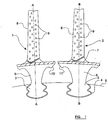
- FIG. 1 This type of general arrangement is illustrated, by way of example, in figure 1 showing two adjacent turbine blades 1, 2, each of which has a root region three of "fir-tree" configuration in cross section.
- the fir-tree root 3 of each turbine blade 1, 2 is received within a complementary recess 4 provided in a central rotor disc 5.
- each rotor blade 1, 2 has a widening stem region 6 beyond which a respective laterally extending platform 7 is provided.
- an aerofoil region 8 Positioned radially outside the platform 7 is an aerofoil region 8 which, in the arrangement illustrated, is provided with a plurality of cooling apertures 9 in a generally conventional manner.
- vibrations typically occur between the turbine blades 1, 2 and the rotor disc 5, and between the turbine blades 1, 2 themselves. Unchecked, this vibration can lead to fatigue of the turbine blades and so it is necessary to provide an arrangement in order to dissipate the energy of these vibrations. This is commonly done by inserting vibration dampers between the adjacent turbine blades, the dampers being arranged to bear against opposed contact surfaces of adjacent blade platforms 7, such as the converging contact surfaces 10, 11 illustrated in figure 1 .
- a typical vibration damper of this type is illustrated at 12 in figure 2 and it can been seen that in the operating position illustrated generally in figure 2 , the damper 12 also performs a secondary function of sealing the small gap 13 between adjacent blade platforms 7.
- the damper 12 also performs a secondary function of sealing the small gap 13 between adjacent blade platforms 7.
- Each vibration damper 12 is arranged so as to have a pair of convergent planar sealing surfaces 14,15 which are urged into sealing engagement with respective convergent contact faces 10,11 of the blade platforms 7 when the damper 12 is subjected to centrifugal loading during operation of the engine.
- convergent planar sealing surfaces 14,15 which are urged into sealing engagement with respective convergent contact faces 10,11 of the blade platforms 7 when the damper 12 is subjected to centrifugal loading during operation of the engine.
- vibration dampers 12 of the general type described above can suffer from a number of disadvantages.
- conventional dampers can have insufficient mass to provide effective damping.
- vibration dampers of the type described above often don't provide particularly effective damping in the case of vibrations occurring as a result of primarily radial relative movement between adjacent turbine blades.
- EP1136653 discloses a turbine rotor with the features of the preamble of claim 1.
- US4872812 discloses a sealing and damping system for a rotor blade platform of a gas turbine.
- a first aspect of the present invention provides a turbine rotor with at least one vibration damper, as described in claim 1.
- the mass-region of the (or each) vibration damper is generally elongate in form and may have a relatively narrow section adjacent the seal-region and a relatively large section radially inwardly thereof.
- the vibration damper has its centre of gravity located substantially within, or generally adjacent, the mass-region.
- the seal-region of the vibration damper may be shaped such that the sealing surfaces converge in a radially outward direction relative to the rotor, for engagement with similarly converging contact surfaces provided on adjacent blade platforms.
- the sealing surfaces make an acute angle to one another.
- the vibration damper may have a mass-distribution such that a line of centrifugal force, acting upon the damper during rotation of the rotor, passes through a mid-chord region of the second of said pair of sealing surfaces.
- turbomachine having at least one turbine rotor of the type identified above.
- each platform is configured to define a first contact surface to one side of the aerofoil, and a second contact surface to the opposite side of the aerofoil, the first contact surface lying in a substantially radial plane relative to the rotor, and the second contact surface lying in a plane making an acute angle to the radial plane.
- said first contact surface is provided on the suction side of the aerofoil, and said second contact face is provided on the pressure side of the aerofoil.
- each rotor blade preferably comprises a projection located substantially radially inwardly of the second contact surface in order to define a recess between the second contact surface and the projection.
- Each vibration damper is then provided such that its seal region is located substantially in a space defined between the first contact surface of one blade, and the second contact surface of an adjacent blade.
- part of the seal-region of the vibration damper extends into said recess, to be loosely located therein.
- prior art vibration dampers for gas turbine engines take the form of a solid mass having a pair of converging planar surfaces arranged to make contact with angled surfaces provided on two neighbouring turbine blade platforms when the damper is subjected to centrifugal loading during rotation of the turbine. It will therefore be clear that such an arrangement necessitates the provision of turbine blades having a contact surface provided on both sides of the aerofoil section of the blade, both of those contact surfaces being angled relative to a radial plane. Such an arrangement has been found to suffer from a number of disadvantages.
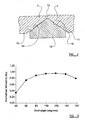
- vibration energy can be more effectively dissipated if the angle between adjacent converging contact faces of the neighbouring turbine blades is reduced (i.e. if the contact faces, or at least one of the contact faces, of a pair of neighbouring turbine blades tends towards the radial direction relative to the turbine rotor).
- figure 3 shows a plot of blade tip-displacement against the "roof angle" between neighbouring converging contact faces. As can be seen, as the "roof angle" is reduced, so the level of tip displacement during vibration reduces.
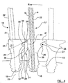
- FIG. 4 illustrates an arrangement in accordance with the present invention, showing a pair of adjacent turbine blades 16, 17.
- the turbine blades are shown in cross-section through their points of maximum chord depth.
- Each blade has a pressure side P and a suction side S, and comprises a radially innermost fir-tree root engaged within a respective complementary recess formed in a rotor disc 19.
- the rotor disc will thus be caused to rotate in an anticlockwise direction R as illustrated in figure 4 .
- Each turbine blade 16, 17 also comprises a respective stem region 20 which extends radially outwardly from the fir-tree root 18 and which carries a platform 21, beyond which a respective aerofoil section 22 extends generally radially with respect to the rotor 19.
- Each platform 21 defines a first contact surface 24 on the suction side of the blade axis 23, and a second contact surface 25 on the pressure side of the blade axis 23.
- the first contact surface 24 of each turbine blade 16, 17 is arranged so as to lie in a plane radial relative to the rotor 19. However, the second contact surface 25 of each turbine blade lies in a plane making an acute angle ⁇ relative to the first contact surface 24.
- Each platform region 21 is also provided with a small projection 26, extending generally (laterally relative to the rotor 19) at a position spaced radially inwardly of the angled second contact surface 25.
- a recess 27 is thus defined between the projection 26 and the angled second contact surface 25.
- the recess 27 is thus provided in the platform 21 on the pressure side P of the blade. This is preferred over the alternative of cutting the recess 27 into the suction side S of the blade, because at the maximum chord-depth position the suction surface of the blade is positioned very close to the edge of the platform as can be seen in figure 4 .
- a recess 27 cut into the suction side S of the blade would thus be very close to the path along which centrifugal load is transmitted through the platform 21, indicated by the shaded region in figure 4 .
- the recess 27 is clear from this load path.
- turbine blades are typically designed such that the suction side S carries more of the load because the leading and trailing edges are usually hotter, may have cooling holes, and are generally more exposed to impact from debris.
- a vibration damper 28 is provided between the adjacent turbine blades 16, 17.
- the vibration damper 28 has a radially outermost seal-region 29 and a radially innermost mass-region 30, the seal-region and the mass-region being interconnected by a relatively narrow neck-region 31.
- the seal-region 29 is located, in use, generally between the platform regions 21 of adjacent turbine blades, whilst the radially inwardly extending mass-region 30 is located in the space 32 provided between adjacent turbine stems 20.
- the seal-region 29 of the damper defines a first sealing surface 33 which is shown to lie in a radial plane relative to the rotor 19 and is thus provided for sealing engagement with the first contact surface 24 of the adjacent blade 17.
- a second sealing surface 34 is also provided and which lies in a plane making an acute angle ⁇ relative to the first sealing surface 33. In this manner, the second sealing surface 34 is provided for sealing engagement with the second contact surface 25 of the adjacent turbine blade 16.
- the relatively narrow neck region 31 of the damper 28 extends from the seal-region 29 in a radially inward direction, past the relatively narrow space between the projection 26 of one turbine blade 16, and the lowermost region of the first contact surface 24 of the neighbouring turbine blade 17.
- the seal-region 29 defines a stepped projecting region 35 which extends outwardly relative to the neck-region 31 and which is received within the recess 27 formed between the two blades. In this manner, the seal-region 29 of the damper 28 is held loosely captive within the space provided between the adjacent blade platforms 21.
- the recess 27 effectively leads the damper. This means that the damper initially loads up on its first sealing surface 24, against the first contact surface 25 of the neighbouring blade, which allows the damper to slide radially outwardly into proper sealing engagement with the opposing contact surfaces 24, 25 of both blades more easily than would be the case if the damper were loading against the angled contact face 25.
- the mass-region 30 of the damper can be considered to take the form of a generally elongate tail terminating with an enlarged region at a position between the stems 20 of adjacent blades.
- the mass-region 30 is shaped such that the majority of its mass lies on same side of the damper as the stepped region 35. This arrangement is effective to ensure that the centre-of-gravity of the entire vibration damper 28, indicated generally at 36 lies substantially radially below a mid-chord point along the second sealing surface 34 of the damper.
- the centre-of-gravity is located within, or at least generally adjacent, the mass-region 30 of the damper.
- the damper 28 has a mass-distribution which is effective such that when the damper 28 is subjected to centrifugal forces during rotation of the rotor, a line of centrifugal force acting upon the damper passes substantially through a mid-chord region of the second sealing surface 34.
- This is desirable because it helps to provide an even distribution of load across the second sealing surface 34 when the second sealing surface is urged into sealing engagement with the second contact surface 25. If the mass-distribution of the damper were such that the line of centrifugal force acting upon the damper during rotation of the rotor were to act close to the edge of the angled second contact surface 25, then the load would be unevenly distributed across the contact face 25 which could adversely effect the quality of seal provided.
- the vibration damper 28 at the present invention can be used with adjacent turbine blades having only one side of their platforms undercut in order to define an angled contact surface 25.
- the damper has a relatively small "roof angle" ⁇ , and in particular an acute roof angle, which provides improved vibration damping with respect to radial movements between adjacent blades.
- the radially inwardly extending mass-region 30 allows the overall mass of the damper to be significantly increased relative to prior art arrangements which do not have a mass-region of the type described above. This gives more scope to provide sufficient mass to the dampers to ensure effective damping action.
Landscapes
- Engineering & Computer Science (AREA)
- Mechanical Engineering (AREA)
- General Engineering & Computer Science (AREA)
- Turbine Rotor Nozzle Sealing (AREA)
Claims (13)
- Rotor de turbine (19) destiné à être utilisé dans une turbomachine, le rotor de turbine (19) ayant une pluralité d'aubes s'étendant radialement, chaque aube ayant une surface portante (22), une plate-forme (21) située radialement vers l'intérieur de la surface portante et ayant un évidement de retenue (27) formé en son sein, et une tige (20) située radialement vers l'intérieur de la plate-forme et ayant au moins un amortisseur de vibrations (28) monté dessus ; l'amortisseur de vibrations (28) ayant une zone d'étanchéité (29) comprenant une paire de surfaces d'étanchéité (33, 34) conçues pour venir en prise avec des surfaces de contact (24, 25) respectives disposées sur des plates-formes d'aube (21) adjacentes, et
ayant une zone de masse (30) conçue pour s'étendre radialement vers l'intérieur à partir de la zone d'étanchéité (29) et pour se terminer à une position (32) située radialement entre des tiges (20) d'aube adjacentes, caractérisé en ce que ladite zone d'étanchéité (29) est formée de sorte qu'une première (33) de ladite paire de surfaces d'étanchéité se trouve dans un plan radial par rapport au rotor (19), pour venir en prise avec une surface de contact radial (24) sur une des plates-formes (21) d'aube adjacentes, et ladite zone d'étanchéité (29) ayant une saillie de retenue (35) conçue pour venir en prise librement dans un évidement de retenue (27) correspondant formé dans l'une des plates-formes (21) d'aube adjacentes, pour une retenue dans ledit évidement (27) lorsque les forces centrifuges agissant sur l'amortisseur de vibrations (28) sont insuffisantes pour pousser les surfaces d'étanchéité (33, 34) en prise avec les surfaces de contact (24, 25), la saillie de retenue (35) étant située radialement vers l'extérieur de la zone de masse (30). - Rotor de turbine (19) selon la revendication 1, caractérisé en ce que ladite région de masse (30) a une section relativement étroite (31) adjacente à ladite zone d'étanchéité (29), et une section relativement grande radialement vers l'intérieur de celle-ci.
- Rotor de turbine (19) selon l'une quelconque des revendications précédentes, caractérisé en ce que le centre de gravité (36) dudit amortisseur (28) est situé dans ladite région de masse (30).
- Rotor de turbine (19) selon l'une quelconque des revendications précédentes, caractérisé en ce que ladite zone d'étanchéité (29) est formée de sorte que lesdites surfaces d'étanchéité (33, 34) convergent dans une direction radialement vers l'extérieur par rapport au rotor (19), pour venir en prise avec des surfaces de contact (24, 25) convergeant de manière similaire sur les plates-formes (21) d'aube adjacentes.
- Rotor de turbine (19) selon la revendication 4, caractérisé en ce que lesdites surfaces d'étanchéité (33, 34) forment un angle aigu entre elles.
- Rotor de turbine (19) selon l'une quelconque des revendications précédentes, caractérisé en ce que ledit amortisseur (28) est conçu de sorte à avoir une distribution de masse telle qu'une ligne de force centrifuge, agissant sur l'amortisseur (28) pendant la rotation du rotor (19), traverse une région de corde centrale de la seconde (34) de ladite paire de surfaces d'étanchéité.
- Rotor de turbine (19) selon l'une quelconque des revendications précédentes, caractérisé en ce que la zone de masse (30) de l'amortisseur (28) prend la forme d'une queue généralement allongée s'étendant depuis la zone d'étanchéité (29) et se terminant avec une zone élargie à une position entre les tiges (20) d'aubes adjacentes.
- Rotor de turbine (19) selon la revendication 7, caractérisé en ce que la zone de masse (30) est formée de sorte que la majeure partie de sa masse se trouve du même côté de l'amortisseur (28) que la saillie de retenue (35).
- Turbomachine ayant au moins un rotor de turbine (19) selon l'une quelconque des revendications précédentes.
- Turbomachine selon la revendication 9, caractérisée en ce que la plate-forme (21) est conçue pour définir une première surface de contact (24) d'un côté de la surface portante, une seconde surface de contact (25) du côté opposé de la surface portante, la première surface de contact (24) se trouvant dans un plan radial par rapport au rotor, et la seconde surface de contact (25) se trouvant dans un plan faisant un angle aigu avec le plan radial.
- Turbomachine selon la revendication 10, caractérisée en ce que ladite première surface de contact est située du côté aspiration (S) de la surface portante (22), et ladite seconde surface de contact (25) est située du côté pression (P) d'une surface portante (22) adjacente.
- Turbomachine selon la revendication 10 ou 11, caractérisée en ce que la plate-forme (21) de chaque aube de rotor (16, 17) comprend une saillie (26) située sensiblement radialement vers l'intérieur de la seconde surface de contact (25) pour définir l'évidement de retenue (27) entre la seconde surface de contact (25) et la saillie (26).
- Turbomachine selon l'une quelconque des revendications 10 à 12, caractérisée en ce que chaque amortisseur (28) est fourni de sorte que sa zone d'étanchéité (29) soit située sensiblement dans un espace défini entre la première surface de contact (24) d'une aube et la seconde surface de contact (25) d'une aube adjacente.
Applications Claiming Priority (1)
| Application Number | Priority Date | Filing Date | Title |
|---|---|---|---|
| GBGB0814018.8A GB0814018D0 (en) | 2008-08-01 | 2008-08-01 | Vibration damper |
Publications (3)
| Publication Number | Publication Date |
|---|---|
| EP2149674A2 EP2149674A2 (fr) | 2010-02-03 |
| EP2149674A3 EP2149674A3 (fr) | 2013-05-01 |
| EP2149674B1 true EP2149674B1 (fr) | 2019-09-04 |
Family
ID=39767296
Family Applications (1)
| Application Number | Title | Priority Date | Filing Date |
|---|---|---|---|
| EP09251733.3A Active EP2149674B1 (fr) | 2008-08-01 | 2009-07-03 | Rotor aubagé de turbine avec amortisseur de vibrations |
Country Status (4)
| Country | Link |
|---|---|
| US (1) | US8322990B2 (fr) |
| EP (1) | EP2149674B1 (fr) |
| JP (1) | JP5329334B2 (fr) |
| GB (1) | GB0814018D0 (fr) |
Families Citing this family (15)
| Publication number | Priority date | Publication date | Assignee | Title |
|---|---|---|---|---|
| FR2962481B1 (fr) * | 2010-07-12 | 2012-08-31 | Snecma Propulsion Solide | Amortisseur de vibrations a bras de levier pour aube d'un rotor de moteur a turbine a gaz |
| US9175570B2 (en) * | 2012-04-24 | 2015-11-03 | United Technologies Corporation | Airfoil including member connected by articulated joint |
| US10641109B2 (en) | 2013-03-13 | 2020-05-05 | United Technologies Corporation | Mass offset for damping performance |
| US9624780B2 (en) * | 2013-12-17 | 2017-04-18 | General Electric Company | System and method for securing axially inserted buckets to a rotor assembly |
| US9810075B2 (en) | 2015-03-20 | 2017-11-07 | United Technologies Corporation | Faceted turbine blade damper-seal |
| JP6763157B2 (ja) | 2016-03-11 | 2020-09-30 | 株式会社Ihi | タービンノズル |
| EP3489464B1 (fr) * | 2016-07-25 | 2021-09-08 | IHI Corporation | Structure de joint d'étanchéité pour aube de rotor de turbine à gaz |
| US10662784B2 (en) | 2016-11-28 | 2020-05-26 | Raytheon Technologies Corporation | Damper with varying thickness for a blade |
| US10677073B2 (en) * | 2017-01-03 | 2020-06-09 | Raytheon Technologies Corporation | Blade platform with damper restraint |
| US10731479B2 (en) * | 2017-01-03 | 2020-08-04 | Raytheon Technologies Corporation | Blade platform with damper restraint |
| EP3438410B1 (fr) | 2017-08-01 | 2021-09-29 | General Electric Company | Système d'étanchéité pour machine rotative |
| US11118458B2 (en) | 2017-10-27 | 2021-09-14 | MTU Aero Engines AG | Combination for sealing a gap between turbomachine blades and for reducing vibrations of the turbomachine blades |
| CN114080490A (zh) * | 2019-05-29 | 2022-02-22 | 赛峰飞机发动机公司 | 用于涡轮机的组件 |
| FR3102506B1 (fr) * | 2019-10-24 | 2022-07-01 | Safran Aircraft Engines | Aube avec organe d’étanchéité amélioré |
| CN113803115B (zh) * | 2020-06-16 | 2024-04-05 | 中国航发商用航空发动机有限责任公司 | 涡轮叶片缘板阻尼器、涡轮叶片和航空发动机 |
Family Cites Families (19)
| Publication number | Priority date | Publication date | Assignee | Title |
|---|---|---|---|---|
| CH494896A (de) * | 1968-08-09 | 1970-08-15 | Sulzer Ag | Halterung von Laufschaufeln im Rotor einer Turbomaschine |
| US3666376A (en) * | 1971-01-05 | 1972-05-30 | United Aircraft Corp | Turbine blade damper |
| US4101245A (en) * | 1976-12-27 | 1978-07-18 | United Technologies Corporation | Interblade damper and seal for turbomachinery rotor |
| US4182598A (en) * | 1977-08-29 | 1980-01-08 | United Technologies Corporation | Turbine blade damper |
| GB2112466A (en) | 1981-12-30 | 1983-07-20 | Rolls Royce | Rotor blade vibration damping |
| US4473337A (en) * | 1982-03-12 | 1984-09-25 | United Technologies Corporation | Blade damper seal |
| US4872812A (en) | 1987-08-05 | 1989-10-10 | General Electric Company | Turbine blade plateform sealing and vibration damping apparatus |
| GB2223277B (en) * | 1988-09-30 | 1992-08-12 | Rolls Royce Plc | Aerofoil blade damping |
| US4872810A (en) * | 1988-12-14 | 1989-10-10 | United Technologies Corporation | Turbine rotor retention system |
| US4936749A (en) | 1988-12-21 | 1990-06-26 | General Electric Company | Blade-to-blade vibration damper |
| US5156528A (en) * | 1991-04-19 | 1992-10-20 | General Electric Company | Vibration damping of gas turbine engine buckets |
| US5478207A (en) * | 1994-09-19 | 1995-12-26 | General Electric Company | Stable blade vibration damper for gas turbine engine |
| JP2000008804A (ja) * | 1998-06-25 | 2000-01-11 | Ishikawajima Harima Heavy Ind Co Ltd | ガスタービンのタービン動翼防振装置 |
| US6042336A (en) * | 1998-11-25 | 2000-03-28 | United Technologies Corporation | Offset center of gravity radial damper |
| GB2344383B (en) | 1998-12-01 | 2002-06-26 | Rolls Royce Plc | A bladed rotor |
| DE10014198A1 (de) | 2000-03-22 | 2001-09-27 | Alstom Power Nv | Beschaufelung mit Dämpfungselementen |
| DE10022244A1 (de) * | 2000-05-08 | 2001-11-15 | Alstom Power Nv | Schaufelanordnung mit Dämpfungselementen |
| US6851932B2 (en) * | 2003-05-13 | 2005-02-08 | General Electric Company | Vibration damper assembly for the buckets of a turbine |
| US7322797B2 (en) * | 2005-12-08 | 2008-01-29 | General Electric Company | Damper cooled turbine blade |
-
2008
- 2008-08-01 GB GBGB0814018.8A patent/GB0814018D0/en active Pending
-
2009
- 2009-07-03 EP EP09251733.3A patent/EP2149674B1/fr active Active
- 2009-07-06 US US12/458,241 patent/US8322990B2/en not_active Expired - Fee Related
- 2009-08-03 JP JP2009180588A patent/JP5329334B2/ja not_active Expired - Fee Related
Non-Patent Citations (1)
| Title |
|---|
| None * |
Also Published As
| Publication number | Publication date |
|---|---|
| JP2010038165A (ja) | 2010-02-18 |
| JP5329334B2 (ja) | 2013-10-30 |
| GB0814018D0 (en) | 2008-09-10 |
| US8322990B2 (en) | 2012-12-04 |
| EP2149674A2 (fr) | 2010-02-03 |
| EP2149674A3 (fr) | 2013-05-01 |
| US20100028135A1 (en) | 2010-02-04 |
Similar Documents
| Publication | Publication Date | Title |
|---|---|---|
| EP2149674B1 (fr) | Rotor aubagé de turbine avec amortisseur de vibrations | |
| EP1451446B1 (fr) | Carenage a poches pour aube de turbine | |
| US8790086B2 (en) | Turbine blade assembly for retaining sealing and dampening elements | |
| CN106948867B (zh) | 带护罩的涡轮转子叶片 | |
| EP2472065B1 (fr) | Couverture d'amortisseur et étanchéité pour aube de turbine | |
| JP4870954B2 (ja) | ガスタービンエンジンロータ組立体を組立てるための方法及び装置 | |
| US5281097A (en) | Thermal control damper for turbine rotors | |
| US6916021B2 (en) | Sealing arrangement | |
| EP2626516B1 (fr) | Agencement de turbine et procédé pour modifier une fréquence de résonance | |
| EP2500520B1 (fr) | Amortisseur et agencement d'étanchéité pour aube de turbine | |
| RU2347913C2 (ru) | Ротор паровой или газовой турбины | |
| RU2541078C2 (ru) | Турбинная лопатка и способ ее изготовления | |
| EP2586975B1 (fr) | Aube rotorique de turbine ayant une plateforme formée pour le contrôle de la température du gaz, rotor de turbine et procédé de commande de flux de purge associés | |
| EP2586974B1 (fr) | Aube rotorique de turbine ayant un gondolage de bord d'attaque de plate-forme pour la performance et le flux secondaire, rotor de turbine et procédé de commande de flux secondaire de purge associés | |
| EP2586995A2 (fr) | Éléments d'aile d'ange pour aube de turbine pour la commande d'écoulement de cavité avant et procédé associé | |
| US7326033B2 (en) | Turbomachine blade | |
| EP2236755A2 (fr) | Aube de rotor de turbine à vapeur avec entretoise intermediaire pour une application à basse pression | |
| JP5507906B2 (ja) | ピボットプレート及びロープシールを備えたシール機構 | |
| US10895159B2 (en) | Removable anti-wear part for blade tip | |
| JP2010019255A (ja) | ロータスロット用のコンプライアントシール | |
| JP6742753B2 (ja) | 侵入損失を制御するためのタービンバケットプラットフォーム | |
| JP5400500B2 (ja) | タービンダブテール用のラビリンスシール | |
| CN106852162B (zh) | 涡轮机的翼片、组件、风机转子及涡轮机 | |
| US7066714B2 (en) | High speed rotor assembly shroud | |
| EP2631427B1 (fr) | Équilibrage de rotors |
Legal Events
| Date | Code | Title | Description |
|---|---|---|---|
| PUAI | Public reference made under article 153(3) epc to a published international application that has entered the european phase |
Free format text: ORIGINAL CODE: 0009012 |
|
| AK | Designated contracting states |
Kind code of ref document: A2 Designated state(s): AT BE BG CH CY CZ DE DK EE ES FI FR GB GR HR HU IE IS IT LI LT LU LV MC MK MT NL NO PL PT RO SE SI SK SM TR |
|
| AX | Request for extension of the european patent |
Extension state: AL BA RS |
|
| PUAL | Search report despatched |
Free format text: ORIGINAL CODE: 0009013 |
|
| AK | Designated contracting states |
Kind code of ref document: A3 Designated state(s): AT BE BG CH CY CZ DE DK EE ES FI FR GB GR HR HU IE IS IT LI LT LU LV MC MK MT NL NO PL PT RO SE SI SK SM TR |
|
| AX | Request for extension of the european patent |
Extension state: AL BA RS |
|
| RIC1 | Information provided on ipc code assigned before grant |
Ipc: F01D 25/06 20060101ALI20130327BHEP Ipc: F01D 5/10 20060101AFI20130327BHEP Ipc: F01D 5/22 20060101ALI20130327BHEP Ipc: F01D 5/26 20060101ALI20130327BHEP |
|
| 17P | Request for examination filed |
Effective date: 20131025 |
|
| RBV | Designated contracting states (corrected) |
Designated state(s): AT BE BG CH CY CZ DE DK EE ES FI FR GB GR HR HU IE IS IT LI LT LU LV MC MK MT NL NO PL PT RO SE SI SK SM TR |
|
| RAP1 | Party data changed (applicant data changed or rights of an application transferred) |
Owner name: ROLLS-ROYCE PLC |
|
| STAA | Information on the status of an ep patent application or granted ep patent |
Free format text: STATUS: EXAMINATION IS IN PROGRESS |
|
| 17Q | First examination report despatched |
Effective date: 20180801 |
|
| GRAP | Despatch of communication of intention to grant a patent |
Free format text: ORIGINAL CODE: EPIDOSNIGR1 |
|
| STAA | Information on the status of an ep patent application or granted ep patent |
Free format text: STATUS: GRANT OF PATENT IS INTENDED |
|
| INTG | Intention to grant announced |
Effective date: 20190412 |
|
| GRAS | Grant fee paid |
Free format text: ORIGINAL CODE: EPIDOSNIGR3 |
|
| GRAA | (expected) grant |
Free format text: ORIGINAL CODE: 0009210 |
|
| STAA | Information on the status of an ep patent application or granted ep patent |
Free format text: STATUS: THE PATENT HAS BEEN GRANTED |
|
| AK | Designated contracting states |
Kind code of ref document: B1 Designated state(s): AT BE BG CH CY CZ DE DK EE ES FI FR GB GR HR HU IE IS IT LI LT LU LV MC MK MT NL NO PL PT RO SE SI SK SM TR |
|
| REG | Reference to a national code |
Ref country code: GB Ref legal event code: FG4D |
|
| REG | Reference to a national code |
Ref country code: CH Ref legal event code: EP |
|
| REG | Reference to a national code |
Ref country code: AT Ref legal event code: REF Ref document number: 1175614 Country of ref document: AT Kind code of ref document: T Effective date: 20190915 |
|
| REG | Reference to a national code |
Ref country code: DE Ref legal event code: R096 Ref document number: 602009059681 Country of ref document: DE |
|
| REG | Reference to a national code |
Ref country code: IE Ref legal event code: FG4D |
|
| REG | Reference to a national code |
Ref country code: NL Ref legal event code: MP Effective date: 20190904 |
|
| REG | Reference to a national code |
Ref country code: LT Ref legal event code: MG4D |
|
| PG25 | Lapsed in a contracting state [announced via postgrant information from national office to epo] |
Ref country code: NO Free format text: LAPSE BECAUSE OF FAILURE TO SUBMIT A TRANSLATION OF THE DESCRIPTION OR TO PAY THE FEE WITHIN THE PRESCRIBED TIME-LIMIT Effective date: 20191204 Ref country code: BG Free format text: LAPSE BECAUSE OF FAILURE TO SUBMIT A TRANSLATION OF THE DESCRIPTION OR TO PAY THE FEE WITHIN THE PRESCRIBED TIME-LIMIT Effective date: 20191204 Ref country code: SE Free format text: LAPSE BECAUSE OF FAILURE TO SUBMIT A TRANSLATION OF THE DESCRIPTION OR TO PAY THE FEE WITHIN THE PRESCRIBED TIME-LIMIT Effective date: 20190904 Ref country code: FI Free format text: LAPSE BECAUSE OF FAILURE TO SUBMIT A TRANSLATION OF THE DESCRIPTION OR TO PAY THE FEE WITHIN THE PRESCRIBED TIME-LIMIT Effective date: 20190904 Ref country code: LT Free format text: LAPSE BECAUSE OF FAILURE TO SUBMIT A TRANSLATION OF THE DESCRIPTION OR TO PAY THE FEE WITHIN THE PRESCRIBED TIME-LIMIT Effective date: 20190904 Ref country code: HR Free format text: LAPSE BECAUSE OF FAILURE TO SUBMIT A TRANSLATION OF THE DESCRIPTION OR TO PAY THE FEE WITHIN THE PRESCRIBED TIME-LIMIT Effective date: 20190904 |
|
| RAP2 | Party data changed (patent owner data changed or rights of a patent transferred) |
Owner name: ROLLS-ROYCE PLC |
|
| PG25 | Lapsed in a contracting state [announced via postgrant information from national office to epo] |
Ref country code: GR Free format text: LAPSE BECAUSE OF FAILURE TO SUBMIT A TRANSLATION OF THE DESCRIPTION OR TO PAY THE FEE WITHIN THE PRESCRIBED TIME-LIMIT Effective date: 20191205 Ref country code: LV Free format text: LAPSE BECAUSE OF FAILURE TO SUBMIT A TRANSLATION OF THE DESCRIPTION OR TO PAY THE FEE WITHIN THE PRESCRIBED TIME-LIMIT Effective date: 20190904 Ref country code: ES Free format text: LAPSE BECAUSE OF FAILURE TO SUBMIT A TRANSLATION OF THE DESCRIPTION OR TO PAY THE FEE WITHIN THE PRESCRIBED TIME-LIMIT Effective date: 20190904 |
|
| REG | Reference to a national code |
Ref country code: AT Ref legal event code: MK05 Ref document number: 1175614 Country of ref document: AT Kind code of ref document: T Effective date: 20190904 |
|
| PG25 | Lapsed in a contracting state [announced via postgrant information from national office to epo] |
Ref country code: PT Free format text: LAPSE BECAUSE OF FAILURE TO SUBMIT A TRANSLATION OF THE DESCRIPTION OR TO PAY THE FEE WITHIN THE PRESCRIBED TIME-LIMIT Effective date: 20200106 Ref country code: PL Free format text: LAPSE BECAUSE OF FAILURE TO SUBMIT A TRANSLATION OF THE DESCRIPTION OR TO PAY THE FEE WITHIN THE PRESCRIBED TIME-LIMIT Effective date: 20190904 Ref country code: NL Free format text: LAPSE BECAUSE OF FAILURE TO SUBMIT A TRANSLATION OF THE DESCRIPTION OR TO PAY THE FEE WITHIN THE PRESCRIBED TIME-LIMIT Effective date: 20190904 Ref country code: AT Free format text: LAPSE BECAUSE OF FAILURE TO SUBMIT A TRANSLATION OF THE DESCRIPTION OR TO PAY THE FEE WITHIN THE PRESCRIBED TIME-LIMIT Effective date: 20190904 Ref country code: IT Free format text: LAPSE BECAUSE OF FAILURE TO SUBMIT A TRANSLATION OF THE DESCRIPTION OR TO PAY THE FEE WITHIN THE PRESCRIBED TIME-LIMIT Effective date: 20190904 Ref country code: RO Free format text: LAPSE BECAUSE OF FAILURE TO SUBMIT A TRANSLATION OF THE DESCRIPTION OR TO PAY THE FEE WITHIN THE PRESCRIBED TIME-LIMIT Effective date: 20190904 Ref country code: EE Free format text: LAPSE BECAUSE OF FAILURE TO SUBMIT A TRANSLATION OF THE DESCRIPTION OR TO PAY THE FEE WITHIN THE PRESCRIBED TIME-LIMIT Effective date: 20190904 |
|
| PG25 | Lapsed in a contracting state [announced via postgrant information from national office to epo] |
Ref country code: IS Free format text: LAPSE BECAUSE OF FAILURE TO SUBMIT A TRANSLATION OF THE DESCRIPTION OR TO PAY THE FEE WITHIN THE PRESCRIBED TIME-LIMIT Effective date: 20200224 Ref country code: SM Free format text: LAPSE BECAUSE OF FAILURE TO SUBMIT A TRANSLATION OF THE DESCRIPTION OR TO PAY THE FEE WITHIN THE PRESCRIBED TIME-LIMIT Effective date: 20190904 Ref country code: CZ Free format text: LAPSE BECAUSE OF FAILURE TO SUBMIT A TRANSLATION OF THE DESCRIPTION OR TO PAY THE FEE WITHIN THE PRESCRIBED TIME-LIMIT Effective date: 20190904 Ref country code: SK Free format text: LAPSE BECAUSE OF FAILURE TO SUBMIT A TRANSLATION OF THE DESCRIPTION OR TO PAY THE FEE WITHIN THE PRESCRIBED TIME-LIMIT Effective date: 20190904 |
|
| REG | Reference to a national code |
Ref country code: DE Ref legal event code: R097 Ref document number: 602009059681 Country of ref document: DE |
|
| PLBE | No opposition filed within time limit |
Free format text: ORIGINAL CODE: 0009261 |
|
| STAA | Information on the status of an ep patent application or granted ep patent |
Free format text: STATUS: NO OPPOSITION FILED WITHIN TIME LIMIT |
|
| PG2D | Information on lapse in contracting state deleted |
Ref country code: IS |
|
| PG25 | Lapsed in a contracting state [announced via postgrant information from national office to epo] |
Ref country code: DK Free format text: LAPSE BECAUSE OF FAILURE TO SUBMIT A TRANSLATION OF THE DESCRIPTION OR TO PAY THE FEE WITHIN THE PRESCRIBED TIME-LIMIT Effective date: 20190904 Ref country code: IS Free format text: LAPSE BECAUSE OF FAILURE TO SUBMIT A TRANSLATION OF THE DESCRIPTION OR TO PAY THE FEE WITHIN THE PRESCRIBED TIME-LIMIT Effective date: 20200105 |
|
| 26N | No opposition filed |
Effective date: 20200605 |
|
| PG25 | Lapsed in a contracting state [announced via postgrant information from national office to epo] |
Ref country code: SI Free format text: LAPSE BECAUSE OF FAILURE TO SUBMIT A TRANSLATION OF THE DESCRIPTION OR TO PAY THE FEE WITHIN THE PRESCRIBED TIME-LIMIT Effective date: 20190904 |
|
| REG | Reference to a national code |
Ref country code: DE Ref legal event code: R119 Ref document number: 602009059681 Country of ref document: DE |
|
| PG25 | Lapsed in a contracting state [announced via postgrant information from national office to epo] |
Ref country code: MC Free format text: LAPSE BECAUSE OF FAILURE TO SUBMIT A TRANSLATION OF THE DESCRIPTION OR TO PAY THE FEE WITHIN THE PRESCRIBED TIME-LIMIT Effective date: 20190904 |
|
| REG | Reference to a national code |
Ref country code: CH Ref legal event code: PL |
|
| GBPC | Gb: european patent ceased through non-payment of renewal fee |
Effective date: 20200703 |
|
| REG | Reference to a national code |
Ref country code: BE Ref legal event code: MM Effective date: 20200731 |
|
| PG25 | Lapsed in a contracting state [announced via postgrant information from national office to epo] |
Ref country code: CH Free format text: LAPSE BECAUSE OF NON-PAYMENT OF DUE FEES Effective date: 20200731 Ref country code: LI Free format text: LAPSE BECAUSE OF NON-PAYMENT OF DUE FEES Effective date: 20200731 Ref country code: IE Free format text: LAPSE BECAUSE OF NON-PAYMENT OF DUE FEES Effective date: 20200703 Ref country code: LU Free format text: LAPSE BECAUSE OF NON-PAYMENT OF DUE FEES Effective date: 20200703 Ref country code: GB Free format text: LAPSE BECAUSE OF NON-PAYMENT OF DUE FEES Effective date: 20200703 Ref country code: FR Free format text: LAPSE BECAUSE OF NON-PAYMENT OF DUE FEES Effective date: 20200731 |
|
| PG25 | Lapsed in a contracting state [announced via postgrant information from national office to epo] |
Ref country code: BE Free format text: LAPSE BECAUSE OF NON-PAYMENT OF DUE FEES Effective date: 20200731 Ref country code: DE Free format text: LAPSE BECAUSE OF NON-PAYMENT OF DUE FEES Effective date: 20210202 |
|
| PG25 | Lapsed in a contracting state [announced via postgrant information from national office to epo] |
Ref country code: TR Free format text: LAPSE BECAUSE OF FAILURE TO SUBMIT A TRANSLATION OF THE DESCRIPTION OR TO PAY THE FEE WITHIN THE PRESCRIBED TIME-LIMIT Effective date: 20190904 Ref country code: MT Free format text: LAPSE BECAUSE OF FAILURE TO SUBMIT A TRANSLATION OF THE DESCRIPTION OR TO PAY THE FEE WITHIN THE PRESCRIBED TIME-LIMIT Effective date: 20190904 Ref country code: CY Free format text: LAPSE BECAUSE OF FAILURE TO SUBMIT A TRANSLATION OF THE DESCRIPTION OR TO PAY THE FEE WITHIN THE PRESCRIBED TIME-LIMIT Effective date: 20190904 |
|
| PG25 | Lapsed in a contracting state [announced via postgrant information from national office to epo] |
Ref country code: MK Free format text: LAPSE BECAUSE OF FAILURE TO SUBMIT A TRANSLATION OF THE DESCRIPTION OR TO PAY THE FEE WITHIN THE PRESCRIBED TIME-LIMIT Effective date: 20190904 |