EP2149296A2 - Automatische Stallbeleuchtungsanpassung - Google Patents
Automatische Stallbeleuchtungsanpassung Download PDFInfo
- Publication number
- EP2149296A2 EP2149296A2 EP09075318A EP09075318A EP2149296A2 EP 2149296 A2 EP2149296 A2 EP 2149296A2 EP 09075318 A EP09075318 A EP 09075318A EP 09075318 A EP09075318 A EP 09075318A EP 2149296 A2 EP2149296 A2 EP 2149296A2
- Authority
- EP
- European Patent Office
- Prior art keywords
- lighting
- control system
- section
- access
- shed
- Prior art date
- Legal status (The legal status is an assumption and is not a legal conclusion. Google has not performed a legal analysis and makes no representation as to the accuracy of the status listed.)
- Granted
Links
Images

Classifications
-
- A—HUMAN NECESSITIES
- A01—AGRICULTURE; FORESTRY; ANIMAL HUSBANDRY; HUNTING; TRAPPING; FISHING
- A01K—ANIMAL HUSBANDRY; AVICULTURE; APICULTURE; PISCICULTURE; FISHING; REARING OR BREEDING ANIMALS, NOT OTHERWISE PROVIDED FOR; NEW BREEDS OF ANIMALS
- A01K1/00—Housing animals; Equipment therefor
-
- A—HUMAN NECESSITIES
- A01—AGRICULTURE; FORESTRY; ANIMAL HUSBANDRY; HUNTING; TRAPPING; FISHING
- A01K—ANIMAL HUSBANDRY; AVICULTURE; APICULTURE; PISCICULTURE; FISHING; REARING OR BREEDING ANIMALS, NOT OTHERWISE PROVIDED FOR; NEW BREEDS OF ANIMALS
- A01K29/00—Other apparatus for animal husbandry
-
- H—ELECTRICITY
- H05—ELECTRIC TECHNIQUES NOT OTHERWISE PROVIDED FOR
- H05B—ELECTRIC HEATING; ELECTRIC LIGHT SOURCES NOT OTHERWISE PROVIDED FOR; CIRCUIT ARRANGEMENTS FOR ELECTRIC LIGHT SOURCES, IN GENERAL
- H05B47/00—Circuit arrangements for operating light sources in general, i.e. where the type of light source is not relevant
- H05B47/10—Controlling the light source
- H05B47/105—Controlling the light source in response to determined parameters
- H05B47/115—Controlling the light source in response to determined parameters by determining the presence or movement of objects or living beings
Definitions
- the present invention relates to a method for the automatic adjustment of lighting in sections of a shed device, such as a separation zone.
- the invention also relates to a control system for a shed device having a number of sections for accommodating animals such as cows, in which a section, such as a separation zone, is provided with adjustable lighting.
- the invention furthermore relates to a device for keeping dairy animals having a plurality of sections.
- a shed device for example having a plurality of production units, in which lactating dairy animals are kept, is known.
- a shed device for keeping dairy animals may be provided with a number of sections. Examples of such sections are first and second production units, as well as a care unit with a plurality of subunits.
- a section can also be part of a production unit.
- An example of a section in a production unit is a production unit which may be provided with at least an accommodation space for a production group of dairy animals which are at the lactation stage.
- the production unit may also be provided with a section with a milking device for milking the production group.
- the shed device may also be provided with a separation space, which is also a section.
- a section can also be a subunit of the care unit, such as a calving unit for accommodating dairy animals during calving separately or a milking device for milking recently calved dairy animals or a sickbay unit for accommodating sick animals separately.
- the various sections, units or subunits can be in connection with one another.
- the connection is preferably a connection which can be walked on, such as a passageway. However, it may also be a connection between buildings.
- the sections may be provided with an access means and/or exit means, preferably an access means/exit means which can stop a dairy animal, so that the dairy animal is kept in the present section or which can allow a dairy animal to change sections.
- the access means is preferably controllable.
- the access means may be connected to a control unit.
- the control unit is able to transmit a signal, referred to below as an access signal, to which the access means reacts and allows an animal access to a specific section.
- an animal can be given access or be barred from access to a specific section in a controlled manner.
- the access means/exit means cooperate with a sensor and an identification means which can be detected by the sensor and is provided on the dairy animal. A signal can be sent from the access means to the control unit.
- the control unit can process the identification signal and return an appropriate access signal to the access means, which then allows the identified animal access to the section determined by the control unit.
- the dairy animal which has been identified by the sensor near the access means can thus be given access to a specific section in accordance with a specific desired treatment.
- a control unit is connected to the sensors (which are positioned on or near the access means) and the access means/exit means and is arranged to control access of the animals to the sections in accordance with specific preferences. Control signals may be transmitted.
- lighting may be provided.
- the lighting may have an on/off switch, by means of which the lighting can be switched on or off.
- the lighting is connected to a power supply.
- the power supply may comprise an adjustable switch which can interrupt the connection to the power supply.
- a sensor such as a movement sensor in order to detect the presence of a dairy animal in a specific section.
- the lighting can be switched off in order to save energy.
- WO 92/20959 describes a control unit for switching a lamp by means of movement sensors.
- this object is achieved by providing a method according to claim 1, in particular by means of a method for the automatic adjustment of lighting in sections of a shed device, such as a separation zone, comprising controlling the lighting, such as adjusting the lighting level of a lighting fixture, for example by adjusting the switching on and switching off of the lighting, in a specific section of the shed.
- the method furthermore comprises allowing access to the specific section of the shed which is effected by means of an access signal.
- the access means can react to this access signal.
- the access signal can be provided and transmitted by a control unit and received by the access means.
- the lighting in this specific section will be controlled, in particular will be adjusted, depending on the granted access to the specific section.
- the access signal which indicates to which section access is granted is used to control the lighting.
- the adjustment of the lighting depends directly on the granted access to the respective section. Because the control of the lighting is, at least for one moment, made dependent on the granted access, the use of sensors for measuring the presence of a dairy animal in a specific section is no longer required.
- the lighting can be controlled independently from presence sensors, which thus become superfluous. This also results in a simplification of the control unit of the lighting and to cost savings.
- dairy animal In order to allow a dairy animal access to a section, said dairy animal is first identified.
- the dairy animal may be provided with an identification tag. This can then be scanned or detected or measured in another way.
- granting access to a section takes place at a location where access to the sections can be controlled and where the dairy animal already has to be observed anyway, such as at the milking robot.
- Another embodiment comprises a receiving space where the dairy animal is received, and from which access is possible to two sections. Access to one section is closed.
- the milking robot can transmit the detection data of a dairy animal to the control system and can receive instructions from the control system to then grant the dairy animal access to a section.
- the detection of a dairy animal is in this case the trigger which prompts the control system to change the access to a section.
- the lighting is provided in the form of power-consuming lighting, such as lamps.
- lighting is provided by means of sunlight.
- This lighting too can be controllable according to the invention by means of blackout screens.
- the section in question is prevented from heating up further on account of sunlight, for example when the screens are completely open and thus block the sunlight out completely.
- Controlling the lighting according to the invention may comprise switching on the lighting, for example the moment that a dairy animal is given access to a section which until that moment was not lit.
- the method can, in addition, also comprise switching off of lighting, when the last dairy animal in a section leaves said section due to it being given access to a subsequent section.
- Control or adjustment of the lighting may furthermore comprise control of a lighting state of the lighting.
- control of the lighting comprises dimming the lighting.
- the method furthermore comprises establishing an occupancy rate of the section, based on the granted access.
- the granted access can be used to compile a table with an occupancy rate of the sections. Allowing access to a specific section results in an increase in the occupancy rate of this new section. The occupancy rate of the previous section decreases.
- the occupancy rate will be zero or one and in particular for this separation section, cost savings can be achieved by the fact that a movement sensor is obsolete and/or the fact that the lighting can be switched off immediately after the animal(s) has/have left the section.
- an occupancy rate of a section equal to zero will lead to the lighting in said section being switched off.
- the power supply of the lighting can be switched off, resulting in a saving of energy.
- the adjustment of the lighting, and in particular the switching on or off will be carried out based on a condition, for example the expiration of a time period.
- a dairy animal is granted access to a subsequent section, the animal will still be present in the previous section for some time.
- the light is not adjusted or switched off immediately.
- the invention also relates to a control system for a shed device.
- the shed device preferably has a number of sections for accommodating animals such as cows, with at least one specific section, such as a separation zone, being provided with lighting.
- the lighting is preferably adjustable.
- the control system which is arranged to at least achieve one of the objects of the invention is connectable, preferably connected, to the lighting or to a power supply of the lighting or to another switch, in particular an on/off-switch, of the lighting, with the control system being arranged to grant access to the section to an animal and with the lighting of said specific section being adjustable by means of the control system, depending on the granted access.
- a control unit signal can be transmitted to the access means by the control system.
- the access means will allow access to a section according to the access signal.
- the access signal may, for example, identify the section to which access is granted.
- the lighting state of the lighting in the section is adjustable.
- the control system is arranged to control the lighting of this specific section, depending on the granted access and in particular depending on the access signal.
- a control system is obtained which is capable of controlling the switching on/switching off/adjustment of the lighting without using sensors to measure the presence of the animals in the respective section.
- the access signal has a double function: on the one hand, it makes it possible to grant animals physical access to a section, on the other hand, the same signal is used for the adjustment and control of the lighting in said section.
- the control system may be a computer.
- the computer may be arranged as a management system for the dairy animals, in particular for optimizing the milk production of said dairy animals.
- the management system may, on the basis of a specific condition, for example because a dairy animal is ill, separate the latter from the other animals by granting said animal access to a separate section.
- control system is connectable, preferably connected, to a controllable access means of the section, wherein the control system controls the controllable access means depending on the granted access.
- the data from the control system can thus be used to control the lighting in at least one of the sections of the shed device.
- the lighting is at least switchable between a switched-on state and a switched-off state
- the control system is arranged to switch the lighting between said switched-on and switched-off states.
- the invention can also comprise switching between two different lighting states.
- control system has a memory, the memory comprising an occupancy fate file, wherein the granted access is stored in the occupancy rate file.
- the occupancy rate can be monitored.
- control system is arranged to switch off the lighting of a section when the occupancy rate file indicates that said section is empty.
- the control system comprises a dimmer which is connectable to the lighting.
- the dimmer may be a separate part of the control system.
- the control system provides power for the lighting and the control system can change the intensity of the lighting using the dimmer by increasing or decreasing the power supply by means of the dimmer.
- control system is connectable, preferably connected, to an adjustable dimmer which is connected to the lighting, wherein the control system is arranged to control the dimmer.
- control system can control the dimmer to reach a desired state with the result that the lighting operates at the desired level of intensity.
- the invention also relates to a shed device comprising a number of sections for accommodating animals such as cows, in which at least a specific section, such as the separation section, has a controllable access means and a controllable lighting, in which the access means and the lighting are connected to the control system as described above.
- controllable access means has at least a position in which an animal has access to the section and a position in which access is blocked. This makes it possible to guide an animal to the section desired by the control system.
- control system is also arranged to monitor the current location of an animal, wherein the control system is connected to detection units.
- detection units can be fitted at the access point to a section. This may be a detection unit on a milking box.
- existing detection units can be used for the method and the system according to the invention.
- the access means may form part of a milking box.
- the milking box comprises a milking robot for automatically connecting teat cups to the teats of a dairy animal.
- a milking box can operate completely automatically and comprises an automatically operable entry and exit gate. These gates can therefore advantageously be used for automatically guiding a dairy animal to a second milking box.
- the lighting also to be controllable depending on the current location of the animal, which is measured.
- part of the building is understood to mean a part of a building which has external walls on three sides, such as a wing, and a separate building is understood to mean a building having external walls on four sides.
- Any connecting parts, such as optionally covered and/or enclosed corridors, which occupy less than half of the respective side, and in particular less than a quarter of the side, are not considered here.
- the advantage of such separate building parts or buildings is that this ensures sufficient, in particular natural, ventilation of the interior space.
- the care unit comprises a plurality of subunits/sections. These can also, advantageously, be accommodated in separate buildings or parts of buildings, but preferably at least in separate spaces. Any risk of contamination is reduced if, in particular, the sickbay unit is housed in a separate building.
- At least one production unit comprises at least two sections with milking boxes, a clean access space which is separate from the accommodation space for access to the milking boxes, as well as at least one separation space for dairy animals which are to be separated from the production group, which separation space is separated from the production space and the access space.
- the number of milking boxes is in this case greater than the number of separation spaces, i.e. for at least one section/access space the associated number of milking boxes is greater than the number of separation spaces, and a controllable passage is then provided between the milking boxes which is arranged to guide a dairy animal to be separated from a first milking box to the separation space via a second milking box.
- Each of the spaces, milking boxes and units mentioned may be a section according to the invention.
- a section preferably has closable or controllable access means.
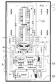
- Figure 1 diagrammatically shows an example of a device 1 according to the invention, in top view, in which reference numeral 20 denotes a production unit and reference numeral 2 denotes a care unit.
- the care unit 2 may comprise a non-lactation unit 3, a calving unit 4 and sickbay unit 7.
- the non-lactation unit 3 comprises boxes and feeding devices for the dairy animals, which are not shown in any more detail.
- the calving units 4 also comprise calving boxes 5, as well as a milking box 6a.
- the sickbay units 7 comprise, for example, a bed 8 and also a milking box 6b.
- the production unit 20 comprises boxes 11, a partition 12, a first and a second milking box 13, 13', a first and a second separation space 14 and 14', as well as a clean access space 15. Access to the clean space is possible via stairs (not shown).
- non-lactation units 3 do not necessarily form part of the care unit 2, since non-lactating dairy animals only require very little care, in practice hardly more than, preferably automated, feeding and the occasional inspection visit. For this reason, the non-lactation units 3 may even be provided furthest from the rest of the care unit 2. However, it may also be advantageous to provide the non-lactation unit as indicated in Figure 1 , in which case the distance to be travelled by the animal remains limited.
- the calving unit 4 comprises calving boxes 5 for animals which have recently calved, as well as a general space for animals which are just about to calve.
- the purpose of the milking device provided in the milking box 6a is to milk mother animals which have recently calved. Firstly, colostrum can be collected in this way and given to the calves, and secondly, the milk production can be stimulated by a targeted milking regime. In addition, the animals require more attention and care during the calving period.
- the sickbay units 7 comprise separated dairy animals, for example sick animals, wounded animals, animals which are too nervous or animals which require additional attention for other reasons, for example dairy animals with an irregular number of teats, etc.
- special beds 8 may be provided, etc. If desired, spaces may be provided which are isolated.
- the milking device which is also provided in the milking box 6b, could for example be provided with special, additional or more sensitive measuring equipment to monitor the animal's health and/or milk quality.
- the milking robot 13,13' can determine whether a dairy animal has, for example, an inflamed teat. Other conditions of the dairy animal can also be determined from the measurement data. Based on the data, a decision can be made whether not to guide a dairy animal to the production unit 20, but instead separate it.
- a dairy animal is guided from the milking robot to the separation space 14,14', via access gate 70, and a farmer can then take the decision to isolate the animal further, for example in a sickbay section 7.
- the farmer can then accompany the dairy animal to said section.
- the dairy animal can leave the separation space via a gate (not shown) and enter the sickbay section 7 via a gate via the intermediate spaces shown around section 5.
- the milking robot 13/13' and/or the control system connected thereto can decide that a dairy animal has to be given access to a non-lactation section 3. This can likewise take place via separation space 14,14', with the farmer accompanying the dairy animal to section 3.
- the production unit 20 houses large numbers of dairy animals. If desired, these can be divided into two or more subgroups, for example with the aid of partition 12, which is only partly shown. Of course, at least one milking box 13, 13' with milking device has to be provided for each subgroup, and advantageously at least two, so that dairy animals have at least one possibility of being milked, even in the event of a malfunction. Other, self-evident components have not been shown, such as milking lines which take the collected milk to storage tanks. Feeding devices, preferably automatic feeding devices, have not been shown either.
- the production unit 20 comprises two milking boxes 13 with a milking device, as well as two sections, such as separation spaces 14, for example for animals which could not be milked or whose milk or behaviour during milking indicates that they are sick. These animals can then, if necessary, be taken to the sickbay units 7. It is also possible for different numbers of milking robots to be provided, for example three or four per production unit.
- Each of the components of the production unit 20, including the milking box 13 itself, may be a section according to the present invention. According to an aspect of the invention, a section is a space to which access can be controlled.
- the milking box 13,13' is in each case provided with detection means for identifying the dairy animal. This detection is carried out in order to link the milking data to the animal. In a shed device, there may also be another unit by means of which animals are identified. The identification can be carried out in different ways.
- the identification data of the milking box 13,13' can be transmitted to a control system for managing access of dairy animals to specific sections. Thus, the control system can be enabled to control access of the dairy animals.
- a separation section 14, 14' is provided for each milking box 13, 13', respectively.
- a simple control system suffices to guide a dairy animal to be separated to the separation space 14, 14' instead of back to the accommodation space.
- the milking box 13,13' is provided with a gate 70, diagrammatically illustrated by a triangle.
- the gate forms the exit of the milking box 13,13', but as such also forms the access point to a section.
- the gate is controllable and thus the gate forms an access point to a section which is remotely controllable and by means of which a control system is able to give or refuse dairy animals access to a section.
- dairy animals are given direct access to a section by means of the access gates 70-72 in accordance with the decision of the management system.
- a dairy animal which has been identified in the milking box 13,13' can, by means of three access gates 70-72,70'-72', be guided back to the production unit 20, to the separation space 14,14', to a section with non-lactation units 3 and calving units 4, or to the sickbay section 7.
- Open connections to the various sections are in each case provided from the three access gates.
- the corridors 60,61 to the sections 3,4,7 are relatively long. At the end of the corridor, near the section, a unidirectional gate 64,64' may be provided, so that a dairy animal cannot reenter the corridor 60,61 from the separate section.
- the access gates 70-72 are connectable or connected to a control system 30.
- the access gates can receive an access signal and upon receipt of said signal will grant an animal access to a specific section of a subsequent path.
- An access gate can give access to one, two, three or a number of sections.
- a clean access space 15 is shown which gives access to the milking robots without an animal having to pass through the accommodation space of the production unit.
- Said access space 15 can also serve as a further partition of the separation space 14, 14'.
- the animals may be provided with an identification means, such as a barcode or a wirelessly determinable identification code.
- This identification means is detectable and a suitable sensor can be used to this end.
- an identification signal can be transmitted to a control system 30.
- access to a separation section 14 can be controlled in accordance with the program of the control system.
- the control system 30 can transmit a suitable access signal to an access gate 70-72 in response to the identification signal.
- the milking box 13 is in each case used to control separation, it is possible to use a different device for this purpose.
- an access gate with feed is provided in order to attract the animals, so that the gate is only opened for an animal to be separated.
- the management system can decide, for example on the basis of measurement data based on the milk (production) of the dairy animal or on the basis of time or on the basis of an externally input parameter, that a dairy animal should return to the production unit 20.
- a controllable gate is provided which either returns the animals to the respective section or, on the contrary, gives access to section 65 of 66, from which a farmer can guide the recovered animal to the production unit.
- a dairy animal can be guided from separation spaces 14,14' to the sections 3,5,7 by the farmer instead of via the corridors.
- Lighting is present in the various sections of the shed device 1 and is in each case denoted by an A.
- the lighting can also comprise a lighting fixture. It is advantageous if each of these lighting fixtures, for example light boxes can be switched between at least two lighting levels, preferably a plurality of levels. To this end, a separate switch may be provided. The switch may form part of the lighting fixture.
- the lighting fixture comprises a dimmer.
- the overall lighting can be dimmed by switching off one or more lighting fixtures A, as a result of which the total lighting level is reduced.
- the control system 30 can transmit an access signal with which an animal is granted access to a specific section.
- the respective access gate or gates will make access possible.
- the access signal can also be used to control the lighting in this section, in particular to switch it on.
- the switch and/or the dimmer may be remote-controlled.
- a connection can be established with the dimmer or switch. This may be a wired or a wireless connection. Via the connection, the dimmer or switch can be controlled and the lighting level of the lighting be controlled. This makes it possible to adjust the lighting level in sections of the shed device. In particular, this makes it possible to save energy, for example by switching off the lighting when there are no animals present in a specific section.
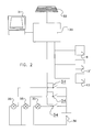
- the invention provides a control system 30, an embodiment of which is shown in Figure 2 .
- the control system is diagrammatically illustrated.
- the control system 30 may be a computer.
- the computer may be connected, via input and output ports, to external units such as a keyboard 32 or a display 31. This makes it possible to interact with the user, so that a user can monitor the current state of the system and/or input different settings.
- the control system 30 is connected to three switches 34.
- the switches 34 are incorporated in the respective circuits of three lighting fixtures 35, which are in each case connected to a power source 36.
- the lighting 35 is represented diagrammatically.
- One lighting fixture 35 can comprise a plurality of light sources.
- the lighting 35 may be a light box.
- the number of connections is flexible. It is also possible to use different switches 34. In addition, it is possible to use a dimmer instead of a switch 34. It is likewise possible for the switch 34 to be part of the lighting fixture. In yet another embodiment, the switch 34 forms part of the power supply 36.
- control system 30 is also connected to the milking boxes 13,13' and 6a,6b according to the embodiment of Figure 1 . It will be clear to those skilled in the art that other connections are also possible. In particular, the control system 30 is connected to the exit of the milking box, which can give access to two or more sections.
- the animal When an animal is being milked in one of the milking robots 13,6, its identity is established.
- the animal can be returned to the production unit 20 by means of a signal from the management system which is incorporated in the control system 30 according to the invention.
- the animal can also be separated off by means of a suitable signal.
- the control system can monitor how many animals are being separated off. Thus, the control system can keep track of the occupancy rate for a section. Based on the occupancy rate, lighting can be switched on or switched off.
- the control system can keep track of the current location of a dairy animal.
- no separate presence sensors are required in the sections in question to determine whether animals are present in said section in order then to switch the lighting on or off, in accordance with the result of the observation.
- Figure 3 shows an example of a table for the occupancy rate.
- the location of a number of cows K1-K11 is indicated.
- Cow K2 is in separation section 14, while cow K6 is in separation section 14'.
- cow K9 is situated in sickbay unit 7. The other cows are in the production unit 20.
- Figure 3 shows a table. It will be clear to those skilled in the art that various embodiments are possible for keeping track of and monitoring the location of the animals.
- the designation of the dairy animal is given.
- a section number (20,14,14'7,3) is indicated.
- An 'x' means that, according to said column, that dairy animal is present in the section. It is possible to define more sections.
- the section comprising the calving unit and non-lactation unit is denoted by a single figure, i.e. 3.
- the illustrated table can be displayed on the display 31 which is connected to the control system 30.
- the table is a representation of the occupancy. Based on the occupancy, an occupancy rate table can be compiled.
- the occupancy rate table based on Figure 3 is as follows: Section Number of dairy animals 20 8 14 1 14' 1 7 1 3/5 0
- the occupancy rate can be given in the form of a table by the control system and can be incorporated into an occupancy rate file which is stored in a memory (not shown) of the control system 30.
- the file can be saved each time a change has occurred.
- the file can be updated following a specific choice by the management system.
- the location of the cow can be changed. If cow K1 is separated off to separation section 14, the cross for K1 in Figure 3 in the column of production unit 20 will be removed and a cross will appear in the column of separation section 14.
- the occupancy rate table in Figure 3 the number of cows present in section 20 will decrease by one to seven and the number of cows present in section 14 will increase to two. In one embodiment, this does not affect the lighting settings.
- the lighting can be switched off on the basis of this finding.
- the switching off can take place immediately after the last cow has left the space or a specific period later.
- the control system can immediately determine the position of a cow and the control system can control the lighting. If a farmer accompanies a dairy animal from the separation space 14/14' to the sections 3/5/7, the arrival of the dairy animal in the section can be recorded by means of a sensor which is present or can be announced by the farmer via a user interface. This procedure also serves to record that it has left the preceding section and to change the occupancy table accordingly.
- the lighting can be switched on.
- the last cow K9 present in sickbay unit 7 is milked using the milking box 6b and said cow is then given access to the production unit 20 instead of being returned to the calving space
- the lighting in the sickbay unit 7 can be switched off.
- the light is already switched off after the cow K9 has entered the milking box 6.
Landscapes
- Life Sciences & Earth Sciences (AREA)
- Environmental Sciences (AREA)
- Animal Husbandry (AREA)
- Biodiversity & Conservation Biology (AREA)
- Zoology (AREA)
- Circuit Arrangement For Electric Light Sources In General (AREA)
- Housing For Livestock And Birds (AREA)
- Feeding And Watering For Cattle Raising And Animal Husbandry (AREA)
Applications Claiming Priority (1)
| Application Number | Priority Date | Filing Date | Title |
|---|---|---|---|
| NL1035772A NL1035772C2 (nl) | 2008-07-28 | 2008-07-28 | Automatisch aanpassen stalverlichting. |
Publications (3)
| Publication Number | Publication Date |
|---|---|
| EP2149296A2 true EP2149296A2 (de) | 2010-02-03 |
| EP2149296A3 EP2149296A3 (de) | 2010-03-10 |
| EP2149296B1 EP2149296B1 (de) | 2011-10-12 |
Family
ID=40290965
Family Applications (1)
| Application Number | Title | Priority Date | Filing Date |
|---|---|---|---|
| EP09075318A Not-in-force EP2149296B1 (de) | 2008-07-28 | 2009-07-20 | Automatische Stallbeleuchtungsanpassung |
Country Status (6)
| Country | Link |
|---|---|
| US (1) | US8232731B2 (de) |
| EP (1) | EP2149296B1 (de) |
| AT (1) | ATE527877T1 (de) |
| CA (1) | CA2673161C (de) |
| DK (1) | DK2149296T3 (de) |
| NL (1) | NL1035772C2 (de) |
Cited By (2)
| Publication number | Priority date | Publication date | Assignee | Title |
|---|---|---|---|---|
| WO2013174841A1 (en) | 2012-05-22 | 2013-11-28 | Robertus Gerardus Alferink | Led luminarie for use in dairy barns |
| WO2015177269A1 (de) * | 2014-05-22 | 2015-11-26 | Gea Farm Technologies Gmbh | Vorrichtung zum gelenkten tierverkehr |
Families Citing this family (2)
| Publication number | Priority date | Publication date | Assignee | Title |
|---|---|---|---|---|
| GB2522020B (en) * | 2014-01-08 | 2018-01-10 | Greengage Lighting Ltd | A method of livestock rearing and a livestock shed |
| NL2015337B1 (nl) * | 2015-08-24 | 2017-03-16 | Lely Patent Nv | Systeem en werkwijze voor het melken van een groep melkdieren. |
Citations (1)
| Publication number | Priority date | Publication date | Assignee | Title |
|---|---|---|---|---|
| WO1992020959A1 (de) | 1991-05-22 | 1992-11-26 | Walter Baenziger | Verfahren zum betätigen einer raumbeleuchtung und vorrichtung zur durchführung des verfahrens |
Family Cites Families (9)
| Publication number | Priority date | Publication date | Assignee | Title |
|---|---|---|---|---|
| US4058740A (en) * | 1975-03-12 | 1977-11-15 | Lok-A-Wat, Inc. | Entry-controlled energy system |
| US4367455A (en) * | 1981-02-12 | 1983-01-04 | Morton Fried | Powersaving room security system |
| US5969637A (en) * | 1996-04-24 | 1999-10-19 | The Chamberlain Group, Inc. | Garage door opener with light control |
| US6097290A (en) * | 1999-01-19 | 2000-08-01 | Balfour; Gilbert A. | Entrance actuated lighting activation system |
| NL1021636C1 (nl) * | 2002-10-11 | 2004-04-14 | Michiel Beheer B V | Traploos multidimbare stalverlichtingsinrichting met een zeer hoog energierendement ten gebruike in de moderne veehouderij. |
| DE10307474A1 (de) * | 2003-02-21 | 2004-09-02 | Merten Gmbh & Co. Kg | Elektro-Hausinstallation |
| US7397342B2 (en) * | 2004-02-19 | 2008-07-08 | Wayne-Dalton Corp. | Operating system for a motorized barrier operator with a radio frequency energized light kit and/or switch and methods for programming the same |
| SE527494C2 (sv) * | 2004-05-24 | 2006-03-21 | Delaval Holding Ab | Anläggning och metoder för automatisk mjölkning av djur |
| GB2432028A (en) * | 2005-11-03 | 2007-05-09 | Steven Thomas Barson | Controlling electrical devices on the basis of occupancy |
-
2008
- 2008-07-28 NL NL1035772A patent/NL1035772C2/nl not_active IP Right Cessation
-
2009
- 2009-07-20 CA CA2673161A patent/CA2673161C/en active Active
- 2009-07-20 DK DK09075318.7T patent/DK2149296T3/da active
- 2009-07-20 EP EP09075318A patent/EP2149296B1/de not_active Not-in-force
- 2009-07-20 AT AT09075318T patent/ATE527877T1/de not_active IP Right Cessation
- 2009-07-28 US US12/510,305 patent/US8232731B2/en not_active Expired - Fee Related
Patent Citations (1)
| Publication number | Priority date | Publication date | Assignee | Title |
|---|---|---|---|---|
| WO1992020959A1 (de) | 1991-05-22 | 1992-11-26 | Walter Baenziger | Verfahren zum betätigen einer raumbeleuchtung und vorrichtung zur durchführung des verfahrens |
Cited By (4)
| Publication number | Priority date | Publication date | Assignee | Title |
|---|---|---|---|---|
| WO2013174841A1 (en) | 2012-05-22 | 2013-11-28 | Robertus Gerardus Alferink | Led luminarie for use in dairy barns |
| US10094520B2 (en) | 2012-05-22 | 2018-10-09 | Delaval Holding Ab | LED luminarie for use in dairy barns |
| WO2015177269A1 (de) * | 2014-05-22 | 2015-11-26 | Gea Farm Technologies Gmbh | Vorrichtung zum gelenkten tierverkehr |
| EA035627B1 (ru) * | 2014-05-22 | 2020-07-17 | Геа Фарм Технолоджиз Гмбх | Установка для направленного движения животных |
Also Published As
| Publication number | Publication date |
|---|---|
| EP2149296A3 (de) | 2010-03-10 |
| US8232731B2 (en) | 2012-07-31 |
| CA2673161A1 (en) | 2010-01-28 |
| US20100019698A1 (en) | 2010-01-28 |
| ATE527877T1 (de) | 2011-10-15 |
| DK2149296T3 (da) | 2011-11-21 |
| NL1035772C2 (nl) | 2010-01-29 |
| EP2149296B1 (de) | 2011-10-12 |
| CA2673161C (en) | 2017-04-04 |
Similar Documents
| Publication | Publication Date | Title |
|---|---|---|
| EP3091833B1 (de) | Verfahren für viehzucht und viehstall | |
| US10582701B2 (en) | Method and system for managing dairy animals | |
| US6837189B2 (en) | Hog facility management system and method | |
| US8087382B2 (en) | Method and arrangement for animal management | |
| EP2149296B1 (de) | Automatische Stallbeleuchtungsanpassung | |
| CN105903681B (zh) | 大圈群养的自动饲喂、自动检测、自动分拣系统 | |
| CN104936440A (zh) | 饲养牲畜的方法和畜棚 | |
| KR20190139611A (ko) | 동물 상태 감시 및 분석 시스템 | |
| US10278358B2 (en) | System and method for managing dairy animals | |
| JP6855060B2 (ja) | 養鶏システム | |
| DK2793557T3 (en) | METHOD AND SYSTEM FOR MANAGING A GROUP OF untethered | |
| US11903368B2 (en) | System for feeding animals | |
| KR20180054968A (ko) | 사양장치 정보를 활용한 이유자돈사 환경 통합관리 장치 및 방법 | |
| EP1541017B1 (de) | Einrichtung und Verfahren zur Verwaltung einer Herde von frei herumlaufenden Tieren | |
| NL4000079B1 (en) | A breeding cage for automatically monitoring animal feces | |
| CA3112174C (en) | Improved system for feeding animals | |
| JPH06209670A (ja) | 養鶏装置 |
Legal Events
| Date | Code | Title | Description |
|---|---|---|---|
| PUAI | Public reference made under article 153(3) epc to a published international application that has entered the european phase |
Free format text: ORIGINAL CODE: 0009012 |
|
| AK | Designated contracting states |
Kind code of ref document: A2 Designated state(s): AT BE BG CH CY CZ DE DK EE ES FI FR GB GR HR HU IE IS IT LI LT LU LV MC MK MT NL NO PL PT RO SE SI SK SM TR |
|
| AX | Request for extension of the european patent |
Extension state: AL BA RS |
|
| PUAL | Search report despatched |
Free format text: ORIGINAL CODE: 0009013 |
|
| AK | Designated contracting states |
Kind code of ref document: A3 Designated state(s): AT BE BG CH CY CZ DE DK EE ES FI FR GB GR HR HU IE IS IT LI LT LU LV MC MK MT NL NO PL PT RO SE SI SK SM TR |
|
| AX | Request for extension of the european patent |
Extension state: AL BA RS |
|
| 17P | Request for examination filed |
Effective date: 20100910 |
|
| 17Q | First examination report despatched |
Effective date: 20101026 |
|
| GRAP | Despatch of communication of intention to grant a patent |
Free format text: ORIGINAL CODE: EPIDOSNIGR1 |
|
| GRAS | Grant fee paid |
Free format text: ORIGINAL CODE: EPIDOSNIGR3 |
|
| GRAA | (expected) grant |
Free format text: ORIGINAL CODE: 0009210 |
|
| AK | Designated contracting states |
Kind code of ref document: B1 Designated state(s): AT BE BG CH CY CZ DE DK EE ES FI FR GB GR HR HU IE IS IT LI LT LU LV MC MK MT NL NO PL PT RO SE SI SK SM TR |
|
| REG | Reference to a national code |
Ref country code: GB Ref legal event code: FG4D |
|
| REG | Reference to a national code |
Ref country code: CH Ref legal event code: EP |
|
| REG | Reference to a national code |
Ref country code: IE Ref legal event code: FG4D |
|
| REG | Reference to a national code |
Ref country code: DK Ref legal event code: T3 |
|
| REG | Reference to a national code |
Ref country code: SE Ref legal event code: TRGR |
|
| REG | Reference to a national code |
Ref country code: NL Ref legal event code: T3 |
|
| REG | Reference to a national code |
Ref country code: DE Ref legal event code: R096 Ref document number: 602009002988 Country of ref document: DE Effective date: 20111215 |
|
| LTIE | Lt: invalidation of european patent or patent extension |
Effective date: 20111012 |
|
| REG | Reference to a national code |
Ref country code: AT Ref legal event code: MK05 Ref document number: 527877 Country of ref document: AT Kind code of ref document: T Effective date: 20111012 |
|
| PG25 | Lapsed in a contracting state [announced via postgrant information from national office to epo] |
Ref country code: BE Free format text: LAPSE BECAUSE OF FAILURE TO SUBMIT A TRANSLATION OF THE DESCRIPTION OR TO PAY THE FEE WITHIN THE PRESCRIBED TIME-LIMIT Effective date: 20111012 Ref country code: NO Free format text: LAPSE BECAUSE OF FAILURE TO SUBMIT A TRANSLATION OF THE DESCRIPTION OR TO PAY THE FEE WITHIN THE PRESCRIBED TIME-LIMIT Effective date: 20120112 Ref country code: IS Free format text: LAPSE BECAUSE OF FAILURE TO SUBMIT A TRANSLATION OF THE DESCRIPTION OR TO PAY THE FEE WITHIN THE PRESCRIBED TIME-LIMIT Effective date: 20120212 Ref country code: LT Free format text: LAPSE BECAUSE OF FAILURE TO SUBMIT A TRANSLATION OF THE DESCRIPTION OR TO PAY THE FEE WITHIN THE PRESCRIBED TIME-LIMIT Effective date: 20111012 |
|
| PG25 | Lapsed in a contracting state [announced via postgrant information from national office to epo] |
Ref country code: HR Free format text: LAPSE BECAUSE OF FAILURE TO SUBMIT A TRANSLATION OF THE DESCRIPTION OR TO PAY THE FEE WITHIN THE PRESCRIBED TIME-LIMIT Effective date: 20111012 Ref country code: SI Free format text: LAPSE BECAUSE OF FAILURE TO SUBMIT A TRANSLATION OF THE DESCRIPTION OR TO PAY THE FEE WITHIN THE PRESCRIBED TIME-LIMIT Effective date: 20111012 Ref country code: LV Free format text: LAPSE BECAUSE OF FAILURE TO SUBMIT A TRANSLATION OF THE DESCRIPTION OR TO PAY THE FEE WITHIN THE PRESCRIBED TIME-LIMIT Effective date: 20111012 Ref country code: PT Free format text: LAPSE BECAUSE OF FAILURE TO SUBMIT A TRANSLATION OF THE DESCRIPTION OR TO PAY THE FEE WITHIN THE PRESCRIBED TIME-LIMIT Effective date: 20120213 Ref country code: GR Free format text: LAPSE BECAUSE OF FAILURE TO SUBMIT A TRANSLATION OF THE DESCRIPTION OR TO PAY THE FEE WITHIN THE PRESCRIBED TIME-LIMIT Effective date: 20120113 |
|
| PG25 | Lapsed in a contracting state [announced via postgrant information from national office to epo] |
Ref country code: CY Free format text: LAPSE BECAUSE OF FAILURE TO SUBMIT A TRANSLATION OF THE DESCRIPTION OR TO PAY THE FEE WITHIN THE PRESCRIBED TIME-LIMIT Effective date: 20111012 |
|
| PLBI | Opposition filed |
Free format text: ORIGINAL CODE: 0009260 |
|
| PG25 | Lapsed in a contracting state [announced via postgrant information from national office to epo] |
Ref country code: SK Free format text: LAPSE BECAUSE OF FAILURE TO SUBMIT A TRANSLATION OF THE DESCRIPTION OR TO PAY THE FEE WITHIN THE PRESCRIBED TIME-LIMIT Effective date: 20111012 Ref country code: CZ Free format text: LAPSE BECAUSE OF FAILURE TO SUBMIT A TRANSLATION OF THE DESCRIPTION OR TO PAY THE FEE WITHIN THE PRESCRIBED TIME-LIMIT Effective date: 20111012 Ref country code: EE Free format text: LAPSE BECAUSE OF FAILURE TO SUBMIT A TRANSLATION OF THE DESCRIPTION OR TO PAY THE FEE WITHIN THE PRESCRIBED TIME-LIMIT Effective date: 20111012 Ref country code: BG Free format text: LAPSE BECAUSE OF FAILURE TO SUBMIT A TRANSLATION OF THE DESCRIPTION OR TO PAY THE FEE WITHIN THE PRESCRIBED TIME-LIMIT Effective date: 20120112 |
|
| 26 | Opposition filed |
Opponent name: DELAVAL INTERNATIONAL AB Effective date: 20120712 |
|
| PG25 | Lapsed in a contracting state [announced via postgrant information from national office to epo] |
Ref country code: PL Free format text: LAPSE BECAUSE OF FAILURE TO SUBMIT A TRANSLATION OF THE DESCRIPTION OR TO PAY THE FEE WITHIN THE PRESCRIBED TIME-LIMIT Effective date: 20111012 Ref country code: IT Free format text: LAPSE BECAUSE OF FAILURE TO SUBMIT A TRANSLATION OF THE DESCRIPTION OR TO PAY THE FEE WITHIN THE PRESCRIBED TIME-LIMIT Effective date: 20111012 Ref country code: RO Free format text: LAPSE BECAUSE OF FAILURE TO SUBMIT A TRANSLATION OF THE DESCRIPTION OR TO PAY THE FEE WITHIN THE PRESCRIBED TIME-LIMIT Effective date: 20111012 |
|
| PLAX | Notice of opposition and request to file observation + time limit sent |
Free format text: ORIGINAL CODE: EPIDOSNOBS2 |
|
| REG | Reference to a national code |
Ref country code: DE Ref legal event code: R026 Ref document number: 602009002988 Country of ref document: DE Effective date: 20120712 |
|
| PLAF | Information modified related to communication of a notice of opposition and request to file observations + time limit |
Free format text: ORIGINAL CODE: EPIDOSCOBS2 |
|
| PG25 | Lapsed in a contracting state [announced via postgrant information from national office to epo] |
Ref country code: AT Free format text: LAPSE BECAUSE OF FAILURE TO SUBMIT A TRANSLATION OF THE DESCRIPTION OR TO PAY THE FEE WITHIN THE PRESCRIBED TIME-LIMIT Effective date: 20111012 |
|
| PG25 | Lapsed in a contracting state [announced via postgrant information from national office to epo] |
Ref country code: MK Free format text: LAPSE BECAUSE OF FAILURE TO SUBMIT A TRANSLATION OF THE DESCRIPTION OR TO PAY THE FEE WITHIN THE PRESCRIBED TIME-LIMIT Effective date: 20111012 Ref country code: MC Free format text: LAPSE BECAUSE OF NON-PAYMENT OF DUE FEES Effective date: 20120731 |
|
| PLBB | Reply of patent proprietor to notice(s) of opposition received |
Free format text: ORIGINAL CODE: EPIDOSNOBS3 |
|
| PG25 | Lapsed in a contracting state [announced via postgrant information from national office to epo] |
Ref country code: ES Free format text: LAPSE BECAUSE OF FAILURE TO SUBMIT A TRANSLATION OF THE DESCRIPTION OR TO PAY THE FEE WITHIN THE PRESCRIBED TIME-LIMIT Effective date: 20120123 |
|
| REG | Reference to a national code |
Ref country code: IE Ref legal event code: MM4A |
|
| PG25 | Lapsed in a contracting state [announced via postgrant information from national office to epo] |
Ref country code: FI Free format text: LAPSE BECAUSE OF FAILURE TO SUBMIT A TRANSLATION OF THE DESCRIPTION OR TO PAY THE FEE WITHIN THE PRESCRIBED TIME-LIMIT Effective date: 20111012 |
|
| PG25 | Lapsed in a contracting state [announced via postgrant information from national office to epo] |
Ref country code: MT Free format text: LAPSE BECAUSE OF FAILURE TO SUBMIT A TRANSLATION OF THE DESCRIPTION OR TO PAY THE FEE WITHIN THE PRESCRIBED TIME-LIMIT Effective date: 20111012 Ref country code: IE Free format text: LAPSE BECAUSE OF NON-PAYMENT OF DUE FEES Effective date: 20120720 |
|
| REG | Reference to a national code |
Ref country code: CH Ref legal event code: PL |
|
| REG | Reference to a national code |
Ref country code: DE Ref legal event code: R100 Ref document number: 602009002988 Country of ref document: DE |
|
| PLCK | Communication despatched that opposition was rejected |
Free format text: ORIGINAL CODE: EPIDOSNREJ1 |
|
| PG25 | Lapsed in a contracting state [announced via postgrant information from national office to epo] |
Ref country code: TR Free format text: LAPSE BECAUSE OF FAILURE TO SUBMIT A TRANSLATION OF THE DESCRIPTION OR TO PAY THE FEE WITHIN THE PRESCRIBED TIME-LIMIT Effective date: 20111012 Ref country code: CH Free format text: LAPSE BECAUSE OF NON-PAYMENT OF DUE FEES Effective date: 20130731 Ref country code: LI Free format text: LAPSE BECAUSE OF NON-PAYMENT OF DUE FEES Effective date: 20130731 |
|
| PG25 | Lapsed in a contracting state [announced via postgrant information from national office to epo] |
Ref country code: LU Free format text: LAPSE BECAUSE OF NON-PAYMENT OF DUE FEES Effective date: 20120720 Ref country code: SM Free format text: LAPSE BECAUSE OF FAILURE TO SUBMIT A TRANSLATION OF THE DESCRIPTION OR TO PAY THE FEE WITHIN THE PRESCRIBED TIME-LIMIT Effective date: 20111012 |
|
| PG25 | Lapsed in a contracting state [announced via postgrant information from national office to epo] |
Ref country code: HU Free format text: LAPSE BECAUSE OF FAILURE TO SUBMIT A TRANSLATION OF THE DESCRIPTION OR TO PAY THE FEE WITHIN THE PRESCRIBED TIME-LIMIT Effective date: 20090720 |
|
| PLBN | Opposition rejected |
Free format text: ORIGINAL CODE: 0009273 |
|
| STAA | Information on the status of an ep patent application or granted ep patent |
Free format text: STATUS: OPPOSITION REJECTED |
|
| 27O | Opposition rejected |
Effective date: 20140319 |
|
| REG | Reference to a national code |
Ref country code: DE Ref legal event code: R100 Ref document number: 602009002988 Country of ref document: DE Effective date: 20140319 |
|
| REG | Reference to a national code |
Ref country code: FR Ref legal event code: PLFP Year of fee payment: 8 |
|
| REG | Reference to a national code |
Ref country code: FR Ref legal event code: PLFP Year of fee payment: 9 |
|
| PGFP | Annual fee paid to national office [announced via postgrant information from national office to epo] |
Ref country code: DK Payment date: 20170725 Year of fee payment: 9 |
|
| REG | Reference to a national code |
Ref country code: FR Ref legal event code: PLFP Year of fee payment: 10 |
|
| REG | Reference to a national code |
Ref country code: DK Ref legal event code: EBP Effective date: 20180731 |
|
| PG25 | Lapsed in a contracting state [announced via postgrant information from national office to epo] |
Ref country code: DK Free format text: LAPSE BECAUSE OF NON-PAYMENT OF DUE FEES Effective date: 20180731 |
|
| PGFP | Annual fee paid to national office [announced via postgrant information from national office to epo] |
Ref country code: GB Payment date: 20190729 Year of fee payment: 11 |
|
| GBPC | Gb: european patent ceased through non-payment of renewal fee |
Effective date: 20200720 |
|
| PG25 | Lapsed in a contracting state [announced via postgrant information from national office to epo] |
Ref country code: GB Free format text: LAPSE BECAUSE OF NON-PAYMENT OF DUE FEES Effective date: 20200720 |
|
| PGFP | Annual fee paid to national office [announced via postgrant information from national office to epo] |
Ref country code: NL Payment date: 20220726 Year of fee payment: 14 |
|
| PGFP | Annual fee paid to national office [announced via postgrant information from national office to epo] |
Ref country code: FR Payment date: 20220725 Year of fee payment: 14 |
|
| P01 | Opt-out of the competence of the unified patent court (upc) registered |
Effective date: 20230505 |
|
| REG | Reference to a national code |
Ref country code: DE Ref legal event code: R084 Ref document number: 602009002988 Country of ref document: DE |
|
| PGFP | Annual fee paid to national office [announced via postgrant information from national office to epo] |
Ref country code: SE Payment date: 20230727 Year of fee payment: 15 |
|
| REG | Reference to a national code |
Ref country code: NL Ref legal event code: MM Effective date: 20230801 |
|
| PG25 | Lapsed in a contracting state [announced via postgrant information from national office to epo] |
Ref country code: NL Free format text: LAPSE BECAUSE OF NON-PAYMENT OF DUE FEES Effective date: 20230801 |
|
| PG25 | Lapsed in a contracting state [announced via postgrant information from national office to epo] |
Ref country code: NL Free format text: LAPSE BECAUSE OF NON-PAYMENT OF DUE FEES Effective date: 20230801 |
|
| PG25 | Lapsed in a contracting state [announced via postgrant information from national office to epo] |
Ref country code: FR Free format text: LAPSE BECAUSE OF NON-PAYMENT OF DUE FEES Effective date: 20230731 |
|
| PGFP | Annual fee paid to national office [announced via postgrant information from national office to epo] |
Ref country code: DE Payment date: 20240729 Year of fee payment: 16 |
|
| REG | Reference to a national code |
Ref country code: SE Ref legal event code: EUG |
|
| PG25 | Lapsed in a contracting state [announced via postgrant information from national office to epo] |
Ref country code: SE Free format text: LAPSE BECAUSE OF NON-PAYMENT OF DUE FEES Effective date: 20240721 |
|
| REG | Reference to a national code |
Ref country code: DE Ref legal event code: R119 Ref document number: 602009002988 Country of ref document: DE |
|
| PG25 | Lapsed in a contracting state [announced via postgrant information from national office to epo] |
Ref country code: DE Free format text: LAPSE BECAUSE OF NON-PAYMENT OF DUE FEES Effective date: 20260203 |