EP2149003B1 - Flowswitch with o-ring seal - Google Patents
Flowswitch with o-ring seal Download PDFInfo
- Publication number
- EP2149003B1 EP2149003B1 EP08799880.3A EP08799880A EP2149003B1 EP 2149003 B1 EP2149003 B1 EP 2149003B1 EP 08799880 A EP08799880 A EP 08799880A EP 2149003 B1 EP2149003 B1 EP 2149003B1
- Authority
- EP
- European Patent Office
- Prior art keywords
- pivot rod
- flowswitch
- rings
- pair
- lubricating
- Prior art date
- Legal status (The legal status is an assumption and is not a legal conclusion. Google has not performed a legal analysis and makes no representation as to the accuracy of the status listed.)
- Active
Links
Images


Classifications
-
- H—ELECTRICITY
- H01—ELECTRIC ELEMENTS
- H01H—ELECTRIC SWITCHES; RELAYS; SELECTORS; EMERGENCY PROTECTIVE DEVICES
- H01H35/00—Switches operated by change of a physical condition
- H01H35/24—Switches operated by change of fluid pressure, by fluid pressure waves, or by change of fluid flow
- H01H35/40—Switches operated by change of fluid pressure, by fluid pressure waves, or by change of fluid flow actuated by devices allowing continual flow of fluid, e.g. vane
Definitions
- the present invention relates to a flowswitch; and more particularly to a flowswitch used to monitor and detect the flow or no flow condition of liquids in pipelines.
- Flowswitches are used to monitor and detect the flow or no-flow condition of liquids in pipelines.
- a flowswitch can make or break an electrical signal when flow or no-flow is detected and is used to actuate a signal when flow stops, start a motor with flow, shut off an alarm when flow is adequate, or stop a motor with no flow.
- a flowswitch typically has a wetted side that installs into the piping that carries the liquid that will actuate the switch, and a dry side with the electrical connections.
- JP 2005-292 113 describes a flowswitch for detecting flowing water according to the preamble of claim 1.
- a similar flowswitch is known from US 3,188,421 .
- One valve device is actuated by fluid flow having a shaft with an O-ring seal arranged in a housing of the valve.
- the other end of the shaft is arranged in a recess having no exposure to the outside environment.
- the shaft has a flat portion for cooperating with a switch button of a switch in a cam-like manner.
- the valve device design has an unbalanced device since the shaft only has an O-ring on one end, and the cam-like relationship between the flat portion and the bottom is likely to contribute to increased friction, especially as the valve device wears.
- One fluid flow sensing device has a pair of O-rings arranged in relation to a shaft.
- the O-rings are not arranged in O-ring grooves; therefore, need washers and nuts to holding them in place on the pivot arm in response to pressurized fluid flowing in the piping.
- One flow switch has side walls with a shaft passing through and connected to a paddle.
- the shaft is not coupled to the side walls on either side with an O-ring.
- the switch is actuated via a magnet and magnetic coupling.
- One fluid flow sensing device has walls with a shaft passing through and connected to a vane.
- the shaft has O-rings and washers that are sufficiently tight to make a fluid-tight seal.
- the shaft also has a spring washer and nut.
- One fluid measuring device has a shaft passing through a central body.
- the shaft has suitable packing, sleeves and nuts.
- the shaft does not have 0- ring grooves for retaining the suitable packing or sleeves.
- One fluid responsive switch has a transverse pin arranged in a central frame structure and has a disc coupled thereto via an arm.
- the pin has an annular resilient material but does not have O-ring grooves.
- One spool deflection indicator does not have a shaft with a pendulant paddle for sensing fluid flow that has O-ring grooves for receiving O-rings.
- One butterfly valve has a shaft with shaft bearings. Although the main body has grooves not labeled for receiving the bearings, the shaft does not have the same.
- One fluid responsive switch pivot arm seal has a pivot arm arranged on a pivot pin with circumferential grooves for receiving an elastomeric material for providing additional bonding between the resilient seal. The pivot arm does not have grooves for receiving the bearings.
- the present invention features a new and unique flowswitch for installing in piping, having a flowswitch base with an inner cavity; a pivot rod being arranged for rotating in the flowswitch base; a paddle arm being coupled to the pivot rod inside the inner cavity, for moving in response to fluid flowing in the piping and rotating the pivot rod; an actuating arm being attached to the pivot rod and configured for actuating a switch when the pivot rod rotates; and lubricating O-rings being arranged in relation to the pivot rod for providing a respective seal between fluid being sensed and the outside environment and acting as a bearing on which the pivot rod rotates when the paddle arm moves.
- the pivot rod is configured with a first pair of machined or formed O-ring grooves separated by a first machined or formed flange, and also configured with a second pair of machined or formed O-ring grooves separated by a second machined or formed flange, wherein a first pair of lubricating O-rings is respectively arranged in the first pair of O-ring grooves and separated by the first flange, and a second pair of lubricating O-rings is respectively arranged in the second pair of O-ring grooves and separated by the second flange, each of the first O-ring grooves and the first flange acting to hold each of the first pair of lubricating O-rings in place on the pivot rod in response to pressurized fluid flowing in the piping, each of the second O-ring grooves and the second flange acting to hold each of the second pair of lubricating O-rings in place on the pivot rod in response to pressurized fluid flowing in the piping, so that the first pair of lubricating O-ring
- the actuating arm may be rigidly coupled between the pivot arm and the pivot rod. The rotation of the pivot arm translates through the actuating arm into a linear position which actuates the switch.
- the paddle arm may be rigidly attached to the pivot arm.
- the switch may be a snap switch that can make or break an electrical signal when flow or no-flow is detected.
- the pivot rod slides through openings in the wall of the flowswitch base, has an enlarged portion on one end for securing the pivot, and has a second portion on the other end for receiving the actuating arm.
- the invention may also include steps for making the flowswitch consistent with that described above.
- the ease of manufacture of the flowswitch is an important aspect of the overall invention.
- Advantages of the O-Ring flow switch design according to the present invention include the following:
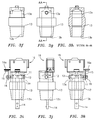
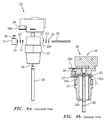
- FIGS 2 - 3k show an O-ring flowswitch generally indicated as 10 according to the present invention, featuring by way of example four lubricated O-rings 11 installed onto a pivot rod 12 with machined or formed O-ring grooves 12a and machined or formed flanges 12b that separate the O-rings 11. As shown, two O-rings are installed on each side of the pivot rod 12.
- the pivot rod 12 is passed through an aperture 13a in a flowswitch base 13 and a paddle arm 14 that is arranged in the middle of an aperture 13b in the flowswitch base 13.
- the pivot rod 12 and aperture 13a are suitably dimensioned so that the O-rings 11 provide a seal between the fluid being sensed and the outside environment.
- the pivot rod 12 and aperture 13a are also suitably dimensioned so that the O-rings 11 also act as a bearing on which the pivot rod 12 rotates when the paddle arm 14 moves as fluid is flowing past the flowswitch 10.
- the scope of the invention is not intended to be limited to any such dimensioning to achieve the aforementioned functionality.
- the paddle arm 14 is rigidly attached by a suitable mechanical means or device 17 to the pivot rod 12; the actuating arm 15 is rigidly attached by a suitable mechanical means or device 18 to the pivot rod 12; and the actuating arm 15 is in contact with actuator 16a of the snap switch 16 by design for actuating the same.
- the scope of the invention is not intended to be limited to any particular type or kind of mechanical technique or way for rigidly attaching the pivot rod 12 to either the paddle arm 14 or the actuating arm 15, or contact of the actuating arm 15 to the actuator 16a.
- Figures 4a - 4k show an alternative O-ring flowswitch generally indicated as 20 which, however, does not make part of the invention, where two lubricated O-rings 21 are installed into a flowswitch base 22 and held in place mechanically by elements or devices 23 and 24.
- the flowswitch base 22 may have internal recesses 22a for receiving the O-rings 21, and the mechanical elements 23 and 24 may include respectively a washer 23 and a suitable mechanical device 24 for holding the same in place.
- the suitable mechanical device 24 may slide into internal recesses 22a and frictionally engage the recess wall for holding the O-ring 21 and washer 22 in place.
- the scope of the invention is not intended to be limited to the manner in which the O-rings are received by the flowswitch base 22, or the manner in which the mechanical elements 23 and 24 hold the O-ring in place.
- the pivot rod 25 is then assembled or passed through an aperture 22b in the flowswitch base 22 and the paddle arm 26 that is in the middle of an aperture 22c of the flowswitch base 22.
- the pivot rod 25, aperture 22a and aperture 22b are suitably dimensioned so that the O-rings 21 provide a seal between the fluid being sensed and the outside environment.
- the pivot rod 25, aperture 22a and aperture 22b are suitably dimensioned so that the O-rings 21 also act as a bearing on which the pivot rod 25 rotates when the paddle arm 26 moves as fluid is flowing past the flowswitch. Consistent with that discussed above, the scope of the invention is not intended to be limited to any such dimensioning to achieve the aforementioned functionality.
- the scope of the invention is not intended to be limited to the number of 0- rings 11, 21 installed on each side of the pivot rod 12, 25.
- embodiments are envisioned in which a minimum of one O-ring is installed on each side of the pivot rod, as well as three, or four, or more O-rings.
- O-rings such as elements 11, 21 are known in the art, and the scope of the invention is not intended to be limited to any particular cross-section, type, or kind thereof, or the materials from which such O-rings are made.
- the scope of the invention is also not intended to be limited to the use of flanges 1 2b between the O-rings 11, because embodiments are envisioned without the use of the same.
- Snap switches such as elements 16, 28 are known in the art and the scope of the invention is not intended to be limited to any particular type or kind thereof. Consistent with that described herein, the actuation of such a snap switch will allow the flowswitch 10, 20 to monitor and detect the flow or no-flow condition of liquids in pipelines (See Figures 5a and 5b ). For example, the flowswitch 10, 20 can make or break an electrical signal when flow or no-flow is detected and actuate a signal when flow stops, start a motor with flow, shut off an alarm when flow is adequate, or stop a motor with no flow. However, it is important to note that the scope of the invention is not intended to be limited to whether a flow or no flow condition is sensed, or the action being taken once such a condition is sensed.
- Figures 5a and 5b show typical applications of a flowswitch 10 or 20 according to the present invention in pipelines generally indicates as 50, 60.
- one pipe 62 has the flowswitch 10 or 20 suitably adapted therein.
Landscapes
- Physics & Mathematics (AREA)
- Fluid Mechanics (AREA)
- Mechanical Sealing (AREA)
- Indicating Or Recording The Presence, Absence, Or Direction Of Movement (AREA)
- Indication Of The Valve Opening Or Closing Status (AREA)
- Multiple-Way Valves (AREA)
- Sealing Devices (AREA)
Applications Claiming Priority (2)
| Application Number | Priority Date | Filing Date | Title |
|---|---|---|---|
| US11/788,776 US7829806B2 (en) | 2007-04-20 | 2007-04-20 | Flowswitch having O-ring pairs arranged in corresponding pairs of O-ring grooves separated by respective flanges of a pivot rod |
| PCT/US2008/057654 WO2008130765A2 (en) | 2007-04-20 | 2008-03-20 | Flowswitch with o-ring seal |
Publications (3)
| Publication Number | Publication Date |
|---|---|
| EP2149003A2 EP2149003A2 (en) | 2010-02-03 |
| EP2149003A4 EP2149003A4 (en) | 2011-07-13 |
| EP2149003B1 true EP2149003B1 (en) | 2016-05-11 |
Family
ID=39871282
Family Applications (1)
| Application Number | Title | Priority Date | Filing Date |
|---|---|---|---|
| EP08799880.3A Active EP2149003B1 (en) | 2007-04-20 | 2008-03-20 | Flowswitch with o-ring seal |
Country Status (8)
| Country | Link |
|---|---|
| US (1) | US7829806B2 (enExample) |
| EP (1) | EP2149003B1 (enExample) |
| JP (1) | JP5139511B2 (enExample) |
| CN (1) | CN101689437B (enExample) |
| AU (1) | AU2008242418B2 (enExample) |
| BR (1) | BRPI0810485B1 (enExample) |
| CA (1) | CA2684733C (enExample) |
| WO (1) | WO2008130765A2 (enExample) |
Families Citing this family (3)
| Publication number | Priority date | Publication date | Assignee | Title |
|---|---|---|---|---|
| US20130125664A1 (en) * | 2011-11-17 | 2013-05-23 | Ronald D. Harper, JR. | Wireless flow monitoring devices |
| CN105453210B (zh) * | 2013-08-06 | 2018-12-04 | 流体处理有限责任公司 | 低水位切断开关 |
| CN112013174B (zh) * | 2020-08-25 | 2022-02-11 | 珠海市广华燃气消防工程有限公司 | 一种天然气管道封堵器 |
Family Cites Families (10)
| Publication number | Priority date | Publication date | Assignee | Title |
|---|---|---|---|---|
| US2203331A (en) | 1937-05-17 | 1940-06-04 | Dearborn Chemicals Co | Flow switch |
| US3065316A (en) | 1959-09-04 | 1962-11-20 | Harold J Olson | Valve device actuated by fluid flow |
| US3188421A (en) * | 1961-12-21 | 1965-06-08 | Scully Signal Co | Fluid flow sensing means |
| US3452169A (en) | 1967-02-20 | 1969-06-24 | Pacific Pumping Co | Flow measuring device |
| US3501605A (en) | 1968-06-26 | 1970-03-17 | Harold D Hutchinson | Flow responsive switch means |
| US4110575A (en) | 1976-06-28 | 1978-08-29 | Meisenheimer Jr Daniel T | Spool deflection indicator |
| US4955785A (en) | 1988-12-05 | 1990-09-11 | Sundstrand Corporation | Fan structure with flow responsive switch mechanism |
| US4926903A (en) | 1989-05-05 | 1990-05-22 | Tomoe Technical Research Company | Butterfly valve having a function for measuring a flow rate and method of measuring a flow rate with a butterfly valve |
| US5602564A (en) * | 1991-11-14 | 1997-02-11 | Hitachi, Ltd. | Graphic data processing system |
| JP2005292113A (ja) * | 2004-03-11 | 2005-10-20 | Senju Sprinkler Kk | 流水検知装置 |
-
2007
- 2007-04-20 US US11/788,776 patent/US7829806B2/en active Active
-
2008
- 2008-03-20 CN CN2008800186747A patent/CN101689437B/zh active Active
- 2008-03-20 CA CA2684733A patent/CA2684733C/en active Active
- 2008-03-20 BR BRPI0810485-9A patent/BRPI0810485B1/pt not_active IP Right Cessation
- 2008-03-20 WO PCT/US2008/057654 patent/WO2008130765A2/en not_active Ceased
- 2008-03-20 JP JP2010504137A patent/JP5139511B2/ja not_active Expired - Fee Related
- 2008-03-20 AU AU2008242418A patent/AU2008242418B2/en active Active
- 2008-03-20 EP EP08799880.3A patent/EP2149003B1/en active Active
Also Published As
| Publication number | Publication date |
|---|---|
| BRPI0810485B1 (pt) | 2019-04-16 |
| CA2684733A1 (en) | 2008-10-30 |
| AU2008242418B2 (en) | 2012-10-11 |
| WO2008130765A2 (en) | 2008-10-30 |
| AU2008242418A1 (en) | 2008-10-30 |
| CN101689437A (zh) | 2010-03-31 |
| JP5139511B2 (ja) | 2013-02-06 |
| US20080258088A1 (en) | 2008-10-23 |
| EP2149003A2 (en) | 2010-02-03 |
| CA2684733C (en) | 2015-05-12 |
| EP2149003A4 (en) | 2011-07-13 |
| WO2008130765A3 (en) | 2010-01-07 |
| BRPI0810485A2 (pt) | 2014-10-14 |
| CN101689437B (zh) | 2012-08-15 |
| JP2010525525A (ja) | 2010-07-22 |
| US7829806B2 (en) | 2010-11-09 |
Similar Documents
| Publication | Publication Date | Title |
|---|---|---|
| US7044444B2 (en) | Actuator element with position detection | |
| US7987871B2 (en) | Switching valve | |
| US8689826B2 (en) | Valve control hand wheel with position indicator and magnetic couple feature | |
| KR100194194B1 (ko) | 회전다이아프램형 유량제어밸브 | |
| US9115812B2 (en) | Plug valve with a spring biased plug | |
| EP2149003B1 (en) | Flowswitch with o-ring seal | |
| US3613518A (en) | Diaphragm actuator | |
| JP4888912B2 (ja) | シール構造およびそのシール構造を用いた制御弁 | |
| CN209370577U (zh) | 具有传感器功能的过程阀 | |
| US5284319A (en) | Eccentrically rotatable sleeve valve | |
| US4085952A (en) | Flexible stem valve | |
| US3257094A (en) | Valve | |
| US6823751B1 (en) | Sphere or pig detection switch assembly | |
| US5132500A (en) | Differential pressure switch with sealed contacts | |
| EP0052743A1 (en) | Seal for fluid intake ports in single lever mixer faucets | |
| JPH0979391A (ja) | ボールバルブ | |
| KR200327415Y1 (ko) | 미압계 | |
| KR20220032557A (ko) | 자기 요소를 갖춘 형상 기억 합금 작동기 부조립체 및 이를 포함하는 유체 밸브 | |
| US4953824A (en) | Deflectable sleeve type valve | |
| RU2141632C1 (ru) | Реле разности давлений | |
| US4822002A (en) | Movable sleeve type valve | |
| US2719020A (en) | Resilient control valve | |
| US2981515A (en) | Motion transmitting device | |
| CN113811708A (zh) | 流路切换阀 | |
| CS243227B1 (cs) | Elektromagnetický kohout |
Legal Events
| Date | Code | Title | Description |
|---|---|---|---|
| PUAI | Public reference made under article 153(3) epc to a published international application that has entered the european phase |
Free format text: ORIGINAL CODE: 0009012 |
|
| AK | Designated contracting states |
Kind code of ref document: A2 Designated state(s): AT BE BG CH CY CZ DE DK EE ES FI FR GB GR HR HU IE IS IT LI LT LU LV MC MT NL NO PL PT RO SE SI SK TR |
|
| AX | Request for extension of the european patent |
Extension state: AL BA MK RS |
|
| R17D | Deferred search report published (corrected) |
Effective date: 20100107 |
|
| RIC1 | Information provided on ipc code assigned before grant |
Ipc: H01H 35/24 20060101AFI20100215BHEP |
|
| RIN1 | Information on inventor provided before grant (corrected) |
Inventor name: GARVEY, JOHN, C. |
|
| 17P | Request for examination filed |
Effective date: 20100707 |
|
| RBV | Designated contracting states (corrected) |
Designated state(s): AT BE BG CH CY CZ DE DK EE ES FI FR GB GR HR HU IE IS IT LI LT LU LV MC MT NL NO PL PT RO SE SI SK TR |
|
| DAX | Request for extension of the european patent (deleted) | ||
| A4 | Supplementary search report drawn up and despatched |
Effective date: 20110610 |
|
| RAP1 | Party data changed (applicant data changed or rights of an application transferred) |
Owner name: XYLEM IP HOLDINGS LLC |
|
| RAP1 | Party data changed (applicant data changed or rights of an application transferred) |
Owner name: XYLEM IP HOLDINGS LLC |
|
| 17Q | First examination report despatched |
Effective date: 20150402 |
|
| GRAP | Despatch of communication of intention to grant a patent |
Free format text: ORIGINAL CODE: EPIDOSNIGR1 |
|
| RIC1 | Information provided on ipc code assigned before grant |
Ipc: H01H 35/40 20060101ALI20151125BHEP Ipc: H01H 35/24 20060101AFI20151125BHEP |
|
| INTG | Intention to grant announced |
Effective date: 20151211 |
|
| GRAS | Grant fee paid |
Free format text: ORIGINAL CODE: EPIDOSNIGR3 |
|
| GRAA | (expected) grant |
Free format text: ORIGINAL CODE: 0009210 |
|
| AK | Designated contracting states |
Kind code of ref document: B1 Designated state(s): AT BE BG CH CY CZ DE DK EE ES FI FR GB GR HR HU IE IS IT LI LT LU LV MC MT NL NO PL PT RO SE SI SK TR |
|
| REG | Reference to a national code |
Ref country code: GB Ref legal event code: FG4D |
|
| REG | Reference to a national code |
Ref country code: CH Ref legal event code: EP |
|
| REG | Reference to a national code |
Ref country code: AT Ref legal event code: REF Ref document number: 799245 Country of ref document: AT Kind code of ref document: T Effective date: 20160515 |
|
| REG | Reference to a national code |
Ref country code: IE Ref legal event code: FG4D |
|
| REG | Reference to a national code |
Ref country code: DE Ref legal event code: R096 Ref document number: 602008044226 Country of ref document: DE |
|
| REG | Reference to a national code |
Ref country code: LT Ref legal event code: MG4D |
|
| REG | Reference to a national code |
Ref country code: NL Ref legal event code: MP Effective date: 20160511 |
|
| PG25 | Lapsed in a contracting state [announced via postgrant information from national office to epo] |
Ref country code: NL Free format text: LAPSE BECAUSE OF FAILURE TO SUBMIT A TRANSLATION OF THE DESCRIPTION OR TO PAY THE FEE WITHIN THE PRESCRIBED TIME-LIMIT Effective date: 20160511 Ref country code: FI Free format text: LAPSE BECAUSE OF FAILURE TO SUBMIT A TRANSLATION OF THE DESCRIPTION OR TO PAY THE FEE WITHIN THE PRESCRIBED TIME-LIMIT Effective date: 20160511 Ref country code: LT Free format text: LAPSE BECAUSE OF FAILURE TO SUBMIT A TRANSLATION OF THE DESCRIPTION OR TO PAY THE FEE WITHIN THE PRESCRIBED TIME-LIMIT Effective date: 20160511 Ref country code: NO Free format text: LAPSE BECAUSE OF FAILURE TO SUBMIT A TRANSLATION OF THE DESCRIPTION OR TO PAY THE FEE WITHIN THE PRESCRIBED TIME-LIMIT Effective date: 20160811 |
|
| REG | Reference to a national code |
Ref country code: AT Ref legal event code: MK05 Ref document number: 799245 Country of ref document: AT Kind code of ref document: T Effective date: 20160511 |
|
| PG25 | Lapsed in a contracting state [announced via postgrant information from national office to epo] |
Ref country code: GR Free format text: LAPSE BECAUSE OF FAILURE TO SUBMIT A TRANSLATION OF THE DESCRIPTION OR TO PAY THE FEE WITHIN THE PRESCRIBED TIME-LIMIT Effective date: 20160812 Ref country code: LV Free format text: LAPSE BECAUSE OF FAILURE TO SUBMIT A TRANSLATION OF THE DESCRIPTION OR TO PAY THE FEE WITHIN THE PRESCRIBED TIME-LIMIT Effective date: 20160511 Ref country code: HR Free format text: LAPSE BECAUSE OF FAILURE TO SUBMIT A TRANSLATION OF THE DESCRIPTION OR TO PAY THE FEE WITHIN THE PRESCRIBED TIME-LIMIT Effective date: 20160511 Ref country code: PT Free format text: LAPSE BECAUSE OF FAILURE TO SUBMIT A TRANSLATION OF THE DESCRIPTION OR TO PAY THE FEE WITHIN THE PRESCRIBED TIME-LIMIT Effective date: 20160912 Ref country code: SE Free format text: LAPSE BECAUSE OF FAILURE TO SUBMIT A TRANSLATION OF THE DESCRIPTION OR TO PAY THE FEE WITHIN THE PRESCRIBED TIME-LIMIT Effective date: 20160511 Ref country code: ES Free format text: LAPSE BECAUSE OF FAILURE TO SUBMIT A TRANSLATION OF THE DESCRIPTION OR TO PAY THE FEE WITHIN THE PRESCRIBED TIME-LIMIT Effective date: 20160511 |
|
| PG25 | Lapsed in a contracting state [announced via postgrant information from national office to epo] |
Ref country code: SK Free format text: LAPSE BECAUSE OF FAILURE TO SUBMIT A TRANSLATION OF THE DESCRIPTION OR TO PAY THE FEE WITHIN THE PRESCRIBED TIME-LIMIT Effective date: 20160511 Ref country code: RO Free format text: LAPSE BECAUSE OF FAILURE TO SUBMIT A TRANSLATION OF THE DESCRIPTION OR TO PAY THE FEE WITHIN THE PRESCRIBED TIME-LIMIT Effective date: 20160511 Ref country code: DK Free format text: LAPSE BECAUSE OF FAILURE TO SUBMIT A TRANSLATION OF THE DESCRIPTION OR TO PAY THE FEE WITHIN THE PRESCRIBED TIME-LIMIT Effective date: 20160511 Ref country code: EE Free format text: LAPSE BECAUSE OF FAILURE TO SUBMIT A TRANSLATION OF THE DESCRIPTION OR TO PAY THE FEE WITHIN THE PRESCRIBED TIME-LIMIT Effective date: 20160511 Ref country code: CZ Free format text: LAPSE BECAUSE OF FAILURE TO SUBMIT A TRANSLATION OF THE DESCRIPTION OR TO PAY THE FEE WITHIN THE PRESCRIBED TIME-LIMIT Effective date: 20160511 |
|
| REG | Reference to a national code |
Ref country code: DE Ref legal event code: R097 Ref document number: 602008044226 Country of ref document: DE |
|
| PG25 | Lapsed in a contracting state [announced via postgrant information from national office to epo] |
Ref country code: BE Free format text: LAPSE BECAUSE OF FAILURE TO SUBMIT A TRANSLATION OF THE DESCRIPTION OR TO PAY THE FEE WITHIN THE PRESCRIBED TIME-LIMIT Effective date: 20160511 Ref country code: PL Free format text: LAPSE BECAUSE OF FAILURE TO SUBMIT A TRANSLATION OF THE DESCRIPTION OR TO PAY THE FEE WITHIN THE PRESCRIBED TIME-LIMIT Effective date: 20160511 Ref country code: AT Free format text: LAPSE BECAUSE OF FAILURE TO SUBMIT A TRANSLATION OF THE DESCRIPTION OR TO PAY THE FEE WITHIN THE PRESCRIBED TIME-LIMIT Effective date: 20160511 |
|
| PLBE | No opposition filed within time limit |
Free format text: ORIGINAL CODE: 0009261 |
|
| STAA | Information on the status of an ep patent application or granted ep patent |
Free format text: STATUS: NO OPPOSITION FILED WITHIN TIME LIMIT |
|
| REG | Reference to a national code |
Ref country code: FR Ref legal event code: PLFP Year of fee payment: 10 |
|
| 26N | No opposition filed |
Effective date: 20170214 |
|
| PG25 | Lapsed in a contracting state [announced via postgrant information from national office to epo] |
Ref country code: SI Free format text: LAPSE BECAUSE OF FAILURE TO SUBMIT A TRANSLATION OF THE DESCRIPTION OR TO PAY THE FEE WITHIN THE PRESCRIBED TIME-LIMIT Effective date: 20160511 |
|
| REG | Reference to a national code |
Ref country code: CH Ref legal event code: PL |
|
| PG25 | Lapsed in a contracting state [announced via postgrant information from national office to epo] |
Ref country code: MC Free format text: LAPSE BECAUSE OF FAILURE TO SUBMIT A TRANSLATION OF THE DESCRIPTION OR TO PAY THE FEE WITHIN THE PRESCRIBED TIME-LIMIT Effective date: 20160511 |
|
| REG | Reference to a national code |
Ref country code: IE Ref legal event code: MM4A |
|
| PG25 | Lapsed in a contracting state [announced via postgrant information from national office to epo] |
Ref country code: LU Free format text: LAPSE BECAUSE OF NON-PAYMENT OF DUE FEES Effective date: 20170320 |
|
| PG25 | Lapsed in a contracting state [announced via postgrant information from national office to epo] |
Ref country code: CH Free format text: LAPSE BECAUSE OF NON-PAYMENT OF DUE FEES Effective date: 20170331 Ref country code: IE Free format text: LAPSE BECAUSE OF NON-PAYMENT OF DUE FEES Effective date: 20170320 Ref country code: LI Free format text: LAPSE BECAUSE OF NON-PAYMENT OF DUE FEES Effective date: 20170331 |
|
| REG | Reference to a national code |
Ref country code: FR Ref legal event code: PLFP Year of fee payment: 11 |
|
| PG25 | Lapsed in a contracting state [announced via postgrant information from national office to epo] |
Ref country code: MT Free format text: LAPSE BECAUSE OF NON-PAYMENT OF DUE FEES Effective date: 20170320 |
|
| PG25 | Lapsed in a contracting state [announced via postgrant information from national office to epo] |
Ref country code: HU Free format text: LAPSE BECAUSE OF FAILURE TO SUBMIT A TRANSLATION OF THE DESCRIPTION OR TO PAY THE FEE WITHIN THE PRESCRIBED TIME-LIMIT; INVALID AB INITIO Effective date: 20080320 |
|
| PG25 | Lapsed in a contracting state [announced via postgrant information from national office to epo] |
Ref country code: BG Free format text: LAPSE BECAUSE OF FAILURE TO SUBMIT A TRANSLATION OF THE DESCRIPTION OR TO PAY THE FEE WITHIN THE PRESCRIBED TIME-LIMIT Effective date: 20160511 |
|
| PG25 | Lapsed in a contracting state [announced via postgrant information from national office to epo] |
Ref country code: CY Free format text: LAPSE BECAUSE OF NON-PAYMENT OF DUE FEES Effective date: 20160511 |
|
| PG25 | Lapsed in a contracting state [announced via postgrant information from national office to epo] |
Ref country code: TR Free format text: LAPSE BECAUSE OF FAILURE TO SUBMIT A TRANSLATION OF THE DESCRIPTION OR TO PAY THE FEE WITHIN THE PRESCRIBED TIME-LIMIT Effective date: 20160511 |
|
| PG25 | Lapsed in a contracting state [announced via postgrant information from national office to epo] |
Ref country code: IS Free format text: LAPSE BECAUSE OF FAILURE TO SUBMIT A TRANSLATION OF THE DESCRIPTION OR TO PAY THE FEE WITHIN THE PRESCRIBED TIME-LIMIT Effective date: 20160911 |
|
| PGFP | Annual fee paid to national office [announced via postgrant information from national office to epo] |
Ref country code: GB Payment date: 20260327 Year of fee payment: 19 |
|
| PGFP | Annual fee paid to national office [announced via postgrant information from national office to epo] |
Ref country code: DE Payment date: 20260327 Year of fee payment: 19 |
|
| PGFP | Annual fee paid to national office [announced via postgrant information from national office to epo] |
Ref country code: IT Payment date: 20260319 Year of fee payment: 19 |
|
| PGFP | Annual fee paid to national office [announced via postgrant information from national office to epo] |
Ref country code: FR Payment date: 20260325 Year of fee payment: 19 |