EP2148118B1 - Dispositif d'habillage pour l'extremite inferieure d'un conduit d'evacuation de fumee depassant sous un plafond ou un faux plafond - Google Patents
Dispositif d'habillage pour l'extremite inferieure d'un conduit d'evacuation de fumee depassant sous un plafond ou un faux plafond Download PDFInfo
- Publication number
- EP2148118B1 EP2148118B1 EP09305693.5A EP09305693A EP2148118B1 EP 2148118 B1 EP2148118 B1 EP 2148118B1 EP 09305693 A EP09305693 A EP 09305693A EP 2148118 B1 EP2148118 B1 EP 2148118B1
- Authority
- EP
- European Patent Office
- Prior art keywords
- ceiling
- covering part
- installation according
- pipe
- barrel
- Prior art date
- Legal status (The legal status is an assumption and is not a legal conclusion. Google has not performed a legal analysis and makes no representation as to the accuracy of the status listed.)
- Active
Links
Images


Classifications
-
- F—MECHANICAL ENGINEERING; LIGHTING; HEATING; WEAPONS; BLASTING
- F16—ENGINEERING ELEMENTS AND UNITS; GENERAL MEASURES FOR PRODUCING AND MAINTAINING EFFECTIVE FUNCTIONING OF MACHINES OR INSTALLATIONS; THERMAL INSULATION IN GENERAL
- F16L—PIPES; JOINTS OR FITTINGS FOR PIPES; SUPPORTS FOR PIPES, CABLES OR PROTECTIVE TUBING; MEANS FOR THERMAL INSULATION IN GENERAL
- F16L5/00—Devices for use where pipes, cables or protective tubing pass through walls or partitions
-
- F—MECHANICAL ENGINEERING; LIGHTING; HEATING; WEAPONS; BLASTING
- F23—COMBUSTION APPARATUS; COMBUSTION PROCESSES
- F23J—REMOVAL OR TREATMENT OF COMBUSTION PRODUCTS OR COMBUSTION RESIDUES; FLUES
- F23J13/00—Fittings for chimneys or flues
- F23J13/04—Joints; Connections
-
- F—MECHANICAL ENGINEERING; LIGHTING; HEATING; WEAPONS; BLASTING
- F23—COMBUSTION APPARATUS; COMBUSTION PROCESSES
- F23J—REMOVAL OR TREATMENT OF COMBUSTION PRODUCTS OR COMBUSTION RESIDUES; FLUES
- F23J13/00—Fittings for chimneys or flues
- F23J13/08—Doors or covers specially adapted for smoke-boxes, flues, or chimneys
Definitions
- the present invention relates to the general field of fumistery. It relates more particularly to a cladding device for the lower end of a smoke evacuation duct protruding under a ceiling or a false ceiling.
- a smoke evacuation duct may be placed between the ceiling (or the false ceiling) of the room in which the heating apparatus is provided, and an external outlet, generally a roof outlet projecting from the roof.
- the upper end of the duct may be associated with a covering structure adapted to achieve sealing on the periphery of the outlet orifice (for example as described in the document DE-20 2007 017476 ).
- the lower end of this exhaust pipe generally exceeds a few centimeters below the ceiling level of the equipped room; this lower end is intended to be connected to the heater by a suitable, visible connection duct.
- the lower end of the smoke evacuation pipe protruding below the ceiling is closed and / or masked.
- the plasterer or the plasterer makes for this on the site, on a case by case basis, a kind of temporary finishing box, plaster or plasterboard, fixed on the ceiling.
- this box is destroyed or simply opened to access the exhaust pipe.
- the site is finalized by a plasterboard connection to the ceiling and / or by fixing a plate of cleanliness.
- the temporary finishing box is not easy to implement; its shaping requires time and is not always very aesthetic.
- being fixed on the ceiling or the false ceiling its weight can pose problems of distribution of loads.
- the finish during the laying of the connecting pipe is also not very easy to achieve and the result obtained may not be aesthetic.
- the object of the present invention is to remedy these disadvantages and to propose a dressing device for the lower end of the exhaust duct of smoke, which is easy to install, aesthetic and does not involve any weight constraint on the ceiling or false ceiling equipped.
- this covering device comprises: either a solid shutter member, when the flue gas outlet duct is not associated with a connection duct, or a shutter member provided with a shutter member. orifice for the passage of a connection duct, in the event of the presence of such a connecting duct connected to said evacuation duct.
- the covering part comprises a cylindrical shell associated with a closure member whose outer circumference is circular.
- the flange of the trim piece has a circular outer periphery. In an alternative embodiment, this outer periphery is square.
- the securing means between the cladding piece and the smoke duct consist of a plurality of threaded rods which assemble each two legs, one secured to the inner face of the ferrule and the other. other integral with the outer face of the flue.
- the lugs integral with the flue pipe are advantageously fixed on an attached clamp.
- the face of the flange which is oriented opposite the shell comprises skids, regularly spaced, for bearing against the face facing the ceiling or false ceiling.
- the closure member is fixed on the shell of the magnetizing lining piece.
- a plurality of magnets are advantageously fixed on integral tabs of the inner face of the shell of the trim piece, which magnets are arranged to ensure the fixing of the removable closure member made of suitable material, such as galvanized steel for example.
- the cladding device 1 comprises a cladding part 2 and means 3 for fixing the cladding piece 2 on the lower end of a smoke evacuation duct 4 (shown in dashed lines). on the figure 3 ).
- the covering part 2 consists of a cylindrical shell 5, one of whose ends (called the “upper” end) is extended by a collar 6 and whose other end (called the “bottom” end) is associated with a removable closure member 7.
- the shell 5, 8 axis can be made of galvanized sheet steel; its diameter can be of the order of 200 to 400 mm and its height of the order of 100 to 300 mm.
- the flange 6, also made of galvanized steel, is secured by welding with the upper end of the ferrule 5; this flange 6 extends in a plane perpendicular to the axis 8 of the ferrule 5; its outer circumference is here circular, but it can also be polygonal, for example square.
- the outer diameter of the circular flange 6 may be of the order of 300 to 500 mm.
- the face 6 'of the flange 6, which is oriented opposite the shell 5 comprises a plurality of regularly spaced skids 9, here eight in number.
- These pads 9 constitute separating members or spacers intended to bear against the ceiling or false ceiling 10 traversed by the smoke evacuation duct 4 to be equipped, in particular to provide ventilation of the internal volume of the cladding device 1, once mounted.
- the pads 9 have a thickness of some mm; they may be made of polyurethane material and they are preferably fixed by gluing.
- the means 3 which ensure the connection between the cladding part 2 and the smoke evacuation duct 4 consist of a plurality of threaded rods 11, here three in number, arranged inside the ferrule 5 and which come together, each, a lug 12 secured to the inner face of the shell 5 and a lug 13 secured to an attached collar 14 adapted to be fixed by clamping on the outer face of the lower end of said exhaust duct of smoke 4.
- the threaded rods 11 extend near the inner face of the shell 5, parallel to the axis 8. Their heads cooperate with the lower legs 12 of ferrule 5 and they are associated with nuts which cooperate with the upper legs 13 necklace 14.
- the tabs 12 consist of small galvanized steel brackets welded at the lower end of the ferrule 5; they are here three in number, regularly distributed on the perimeter of the ferrule.
- the tabs 13 consist of small brackets welded to the clamp 14; they are also here three in number, regularly distributed on the perimeter of the necklace.
- the screw / nut system 15 which allows the clamping and loosening maneuvers of the collar 14.
- the member 7 for closing the lower opening of the shell 5 consists of a plate, here circular galvanized steel, removably attached by magnetization.
- the shell 5 thus comprises means for fixing the removable closure member 7.
- the inner face of the lower end of the shell 5 comprises a plurality of lugs 16, here three in number, mounted between the legs 12 above, and whose lower face is equipped with an attached magnet 17 fixed by any suitable means (for example by magnetization.)
- the "hooking" magnets 17 extend in the plane of the lower circular edge of the shell 5 , to cooperate with the upper face of the shutter plate 7, as appears on the figure 3 .
- the shutter member 7 is equipped with a circular peripheral return 18, oriented upwards, which facilitates its positioning on the shell 5 and which provides an aesthetic finish. In this way the shutter member 7 is properly secured to the trim piece 2; and it can very easily be removed and repositioned at will.
- the closure member 7 may be arranged to ensure its removable attachment to the shell 5 by snapping or closing type quarter turn.
- the closure member 7 is chosen, provided with a central orifice 19, as illustrated on FIG. the figures 2 and 3 (In case of presence of a connecting duct, to allow the passage of the latter), either full, that is to say without a central orifice (in the absence of connection duct).
- the diameter of this central orifice 19 is adapted to the diameter of the connecting duct.
- the choice of the shutter member used is a function of the configuration encountered.
- the device 1 is adapted to "dress" the lower end of a smoke evacuation duct 4 which extends generally from a chimney exiting the roof, to a ceiling or false ceiling and which exceeds a few centimeters under this ceiling or false ceiling, that the exhaust duct 4 is waiting to be associated with a connecting duct equipping a stove-type or stove-type heater, or that the exhaust duct 4 is actually associated with such a connecting pipe.
- the diameter of the ferrule 5 of the cladding part 2 is greater than the diameter of the smoke evacuation duct 4 equipped.
- the external diameter of the flange 6 is, on its side, greater than the diameter of the through hole 20.
- the first operation is to fix the clamp 14 on the outer periphery of the lower end of the smoke outlet duct 4, for example at the underside of the ceiling or false ceiling 10, or just above.
- the smoke evacuation duct 4 is here equipped with a reduction piece 21 (for example a conical reduction), fixed by a clamping collar 22.
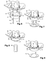
- the covering part 2 can be attached ( figure 6 ) and fixed co-axially to said duct 4, by means of the threaded rods 11 cooperating with the pairs of legs 12, 13, until the upper face 6 'of the collar 6 bears against the underside ceiling or false ceiling 10 ( figure 7 ), via the spacer pads 9.
- the piece 2 is then suspended in the conduit 4, under the latter.
- the operation of the threaded rods 11 is effected by the lower opening of the shell 5 and inside thereof.
- the lower orifice of the ferrule 5 is closed by a closure member 7 (held by the magnets 17), provided with a central orifice 19 for the passage of the connecting pipe ( figure 7 ).
- the assembly is finalized by the installation of the connecting pipe 23 ( figure 8 ), for example of the enameled duct type, by penetration into the cladding device 1 (threading on the reduction 21 by passage between the latter and the edge of the orifice 19).
- the cladding device 1 is placed in the absence of the reduction room 21.
- the dressing room 2 is attached to the smoke outlet duct 4 by the threaded rods 11 and the lower opening of the shell 5 is closed by a solid closure member 7 '(that is to say without a central orifice), as illustrated on the figure 9 .
- the solid closure member 7 ' is deposited and the lower end of the smoke evacuation duct 4 can be equipped with the reduction piece 21 and the connecting duct 23 to obtain the assembly illustrated on the Figures 7 and 8 .
- the dressing device according to the invention is very easy to install, and possibly to remove and rest. It allows a perfect finish between the flue and the connecting duct.
- This cladding device is also self-supporting and therefore does not bear any load on the ceiling or false ceiling crossed. This cladding device makes it possible to mask the adjustment and expansion part of the connecting duct, which part advantageously facilitates the assembly and maintenance of the heating apparatus.
- the covering part 2 and the closure member 7,7 ' can be proposed in several finishes or colors, for example black or white. They can also be repainted in the desired color on the job site.
Landscapes
- Engineering & Computer Science (AREA)
- General Engineering & Computer Science (AREA)
- Mechanical Engineering (AREA)
- Incineration Of Waste (AREA)
- Duct Arrangements (AREA)
Priority Applications (1)
| Application Number | Priority Date | Filing Date | Title |
|---|---|---|---|
| PL09305693T PL2148118T3 (pl) | 2008-07-23 | 2009-07-22 | Urządzenie pokrywające do dolnego końca kanału odprowadzania spalin wystającego pod sufitem lub sufitem podwieszanym |
Applications Claiming Priority (1)
| Application Number | Priority Date | Filing Date | Title |
|---|---|---|---|
| FR0855016A FR2934287B1 (fr) | 2008-07-23 | 2008-07-23 | Dispositif d'habillage pour l'extremite inferieure d'un conduit d'evacuation de fumee depassant sous un plafond ou un faux plafond |
Publications (2)
| Publication Number | Publication Date |
|---|---|
| EP2148118A1 EP2148118A1 (fr) | 2010-01-27 |
| EP2148118B1 true EP2148118B1 (fr) | 2013-05-22 |
Family
ID=40552077
Family Applications (1)
| Application Number | Title | Priority Date | Filing Date |
|---|---|---|---|
| EP09305693.5A Active EP2148118B1 (fr) | 2008-07-23 | 2009-07-22 | Dispositif d'habillage pour l'extremite inferieure d'un conduit d'evacuation de fumee depassant sous un plafond ou un faux plafond |
Country Status (5)
| Country | Link |
|---|---|
| EP (1) | EP2148118B1 (pl) |
| DK (1) | DK2148118T3 (pl) |
| ES (1) | ES2424980T3 (pl) |
| FR (1) | FR2934287B1 (pl) |
| PL (1) | PL2148118T3 (pl) |
Families Citing this family (2)
| Publication number | Priority date | Publication date | Assignee | Title |
|---|---|---|---|---|
| FR2960043B1 (fr) * | 2010-05-11 | 2014-07-11 | Dixneuf Atel | Dispositif d'habillage pour l'extremite inferieure d'un conduit d'evacuation de fumee depassant sous un plafond ou un faux-plafond par un orifice menage dans ce dernier |
| CN108412156B (zh) * | 2018-05-31 | 2019-07-16 | 贵州环科环境工程有限公司 | 烟气排烟管及管道支架 |
Family Cites Families (3)
| Publication number | Priority date | Publication date | Assignee | Title |
|---|---|---|---|---|
| US3874363A (en) * | 1973-11-20 | 1975-04-01 | Luxaire Inc | Vent cap assembly for exteriorly located fuel burning unit |
| US5791985A (en) * | 1995-06-06 | 1998-08-11 | Tapco International | Modular soffit vent |
| DE202007017476U1 (de) * | 2006-10-19 | 2008-04-03 | Bächle, Dieter | Vorrichtung zum zeitweiligen Befestigen einer Rohreinheit |
-
2008
- 2008-07-23 FR FR0855016A patent/FR2934287B1/fr active Active
-
2009
- 2009-07-22 EP EP09305693.5A patent/EP2148118B1/fr active Active
- 2009-07-22 DK DK09305693.5T patent/DK2148118T3/da active
- 2009-07-22 PL PL09305693T patent/PL2148118T3/pl unknown
- 2009-07-22 ES ES09305693T patent/ES2424980T3/es active Active
Also Published As
| Publication number | Publication date |
|---|---|
| PL2148118T3 (pl) | 2013-10-31 |
| ES2424980T3 (es) | 2013-10-10 |
| FR2934287B1 (fr) | 2016-05-13 |
| EP2148118A1 (fr) | 2010-01-27 |
| FR2934287A1 (fr) | 2010-01-29 |
| DK2148118T3 (da) | 2013-08-19 |
Similar Documents
| Publication | Publication Date | Title |
|---|---|---|
| FR3064723B1 (fr) | Dosseret de chaudiere murale a gaz et chaudiere equipee d'un tel dosseret | |
| FR2907144A1 (fr) | Filtre pour tuyau de descente d'eaux | |
| EP1348815B1 (fr) | Agencement, procédé et dispositif pour le montage et le raccordement d'une conduite d'installation sanitaire | |
| EP3219873A1 (fr) | Boîte de réservation pour l'incorporation de canalisations adaptée pour être positionnée sur une armature | |
| EP2053175A1 (fr) | Paroi amovible destinee à être montée sur une surface et procédé de recouvrement d'une surface par une paroi amovible | |
| EP1918594B1 (fr) | Dispositif de garnitures de guidage pour colonnes télescopiques en particulier pour appareils élévateurs | |
| EP2148118A1 (fr) | Dispositif d'habillage pour l'extremite inferieure d'un conduit d'evacuation de fumee depassant sous un plafond ou un faux plafond | |
| EP3067477A1 (fr) | Dispositif de fixation pour bâti support, ensemble de fixation comprenant un tel dispositif et procédé de fixation sur un bâti support | |
| EP2530380B1 (fr) | Installation de chauffage comprenant un appareil de chauffage à bois, une sortie de bâtiment et un conduit de liaison | |
| EP2149751B1 (fr) | Dispositif d'habillage pour un conduit assurant le raccordement entre un appareil de chauffage et un conduit d'évacuation de fumée, et son procédé de mise en oeuvre | |
| FR3036463A1 (fr) | Dispositif pour l'implantation au sol d'une chaudiere de type "murale". | |
| FR2951809A1 (fr) | Equipement pour le passage d'un conduit d'evacuation de fumee connecte a une chaudiere, au travers d'une lumiere d'un boisseau de cheminee maconne | |
| WO1989000634A1 (fr) | Dispositif de fixation ponctuelle d'elements presentant un bord, notamment de plaques sur une structure support | |
| FR3048488B1 (fr) | Installation de chauffage pour un batiment | |
| BE1010812A3 (fr) | Dispositif de fixation pour radiateurs de chauffage. | |
| FR2853954A1 (fr) | Dispositif de protection et d'habillage du raccord entre un conduit d'evacuation des gaz d'un poele et un conduit de cheminee | |
| FR3001748A1 (fr) | Dispositif pour realiser un doublage le long d'un mur existant, en matiere legere coulee par paliers ou en lits successifs, dans un coffrage | |
| FR2790775A1 (fr) | Ensemble de suspente anti-vibrations a deux degres de liberte comportant un bloc elastique, un organe porteur et un corps, et bloc elastique, organe porteur et corps pour un tel ensemble | |
| FR2932874A1 (fr) | Chaise pour foyer de cheminee | |
| FR3016430B1 (fr) | Extracteur statique pour conduit d’evacuation d’air ou d’aeration | |
| FR3048760A1 (fr) | Dispositif de recuperation de liquide de nettoyage lors de l'entretien d'une chaudiere | |
| FR2967185A3 (fr) | Bec pour piscines | |
| FR2896632A1 (fr) | Armature d'armoire pour appareils electriques comportant des traverses et des montants relies par un profile d'emboitement | |
| FR2685432A1 (fr) | Manchon de liaison et son procede de montage. | |
| FR2654461A1 (fr) | Dispositif de crosse pour l'amenagement d'une main courante escamotable dans les chambres de tirage et fosses similaires. |
Legal Events
| Date | Code | Title | Description |
|---|---|---|---|
| PUAI | Public reference made under article 153(3) epc to a published international application that has entered the european phase |
Free format text: ORIGINAL CODE: 0009012 |
|
| AK | Designated contracting states |
Kind code of ref document: A1 Designated state(s): AT BE BG CH CY CZ DE DK EE ES FI FR GB GR HR HU IE IS IT LI LT LU LV MC MK MT NL NO PL PT RO SE SI SK SM TR |
|
| AX | Request for extension of the european patent |
Extension state: AL BA RS |
|
| 17P | Request for examination filed |
Effective date: 20100113 |
|
| 17Q | First examination report despatched |
Effective date: 20100210 |
|
| GRAP | Despatch of communication of intention to grant a patent |
Free format text: ORIGINAL CODE: EPIDOSNIGR1 |
|
| GRAS | Grant fee paid |
Free format text: ORIGINAL CODE: EPIDOSNIGR3 |
|
| GRAA | (expected) grant |
Free format text: ORIGINAL CODE: 0009210 |
|
| AK | Designated contracting states |
Kind code of ref document: B1 Designated state(s): AT BE BG CH CY CZ DE DK EE ES FI FR GB GR HR HU IE IS IT LI LT LU LV MC MK MT NL NO PL PT RO SE SI SK SM TR |
|
| REG | Reference to a national code |
Ref country code: GB Ref legal event code: FG4D Free format text: NOT ENGLISH |
|
| REG | Reference to a national code |
Ref country code: CH Ref legal event code: EP |
|
| REG | Reference to a national code |
Ref country code: AT Ref legal event code: REF Ref document number: 613408 Country of ref document: AT Kind code of ref document: T Effective date: 20130615 |
|
| REG | Reference to a national code |
Ref country code: IE Ref legal event code: FG4D Free format text: LANGUAGE OF EP DOCUMENT: FRENCH |
|
| REG | Reference to a national code |
Ref country code: DE Ref legal event code: R096 Ref document number: 602009015862 Country of ref document: DE Effective date: 20130718 |
|
| REG | Reference to a national code |
Ref country code: DK Ref legal event code: T3 |
|
| REG | Reference to a national code |
Ref country code: NL Ref legal event code: T3 |
|
| REG | Reference to a national code |
Ref country code: ES Ref legal event code: FG2A Ref document number: 2424980 Country of ref document: ES Kind code of ref document: T3 Effective date: 20131010 |
|
| REG | Reference to a national code |
Ref country code: AT Ref legal event code: MK05 Ref document number: 613408 Country of ref document: AT Kind code of ref document: T Effective date: 20130522 |
|
| REG | Reference to a national code |
Ref country code: LT Ref legal event code: MG4D |
|
| PG25 | Lapsed in a contracting state [announced via postgrant information from national office to epo] |
Ref country code: PT Free format text: LAPSE BECAUSE OF FAILURE TO SUBMIT A TRANSLATION OF THE DESCRIPTION OR TO PAY THE FEE WITHIN THE PRESCRIBED TIME-LIMIT Effective date: 20130923 Ref country code: AT Free format text: LAPSE BECAUSE OF FAILURE TO SUBMIT A TRANSLATION OF THE DESCRIPTION OR TO PAY THE FEE WITHIN THE PRESCRIBED TIME-LIMIT Effective date: 20130522 Ref country code: NO Free format text: LAPSE BECAUSE OF FAILURE TO SUBMIT A TRANSLATION OF THE DESCRIPTION OR TO PAY THE FEE WITHIN THE PRESCRIBED TIME-LIMIT Effective date: 20130822 Ref country code: FI Free format text: LAPSE BECAUSE OF FAILURE TO SUBMIT A TRANSLATION OF THE DESCRIPTION OR TO PAY THE FEE WITHIN THE PRESCRIBED TIME-LIMIT Effective date: 20130522 Ref country code: IS Free format text: LAPSE BECAUSE OF FAILURE TO SUBMIT A TRANSLATION OF THE DESCRIPTION OR TO PAY THE FEE WITHIN THE PRESCRIBED TIME-LIMIT Effective date: 20130922 Ref country code: GR Free format text: LAPSE BECAUSE OF FAILURE TO SUBMIT A TRANSLATION OF THE DESCRIPTION OR TO PAY THE FEE WITHIN THE PRESCRIBED TIME-LIMIT Effective date: 20130823 Ref country code: LT Free format text: LAPSE BECAUSE OF FAILURE TO SUBMIT A TRANSLATION OF THE DESCRIPTION OR TO PAY THE FEE WITHIN THE PRESCRIBED TIME-LIMIT Effective date: 20130522 Ref country code: SE Free format text: LAPSE BECAUSE OF FAILURE TO SUBMIT A TRANSLATION OF THE DESCRIPTION OR TO PAY THE FEE WITHIN THE PRESCRIBED TIME-LIMIT Effective date: 20130522 Ref country code: SI Free format text: LAPSE BECAUSE OF FAILURE TO SUBMIT A TRANSLATION OF THE DESCRIPTION OR TO PAY THE FEE WITHIN THE PRESCRIBED TIME-LIMIT Effective date: 20130522 |
|
| REG | Reference to a national code |
Ref country code: PL Ref legal event code: T3 |
|
| PG25 | Lapsed in a contracting state [announced via postgrant information from national office to epo] |
Ref country code: BG Free format text: LAPSE BECAUSE OF FAILURE TO SUBMIT A TRANSLATION OF THE DESCRIPTION OR TO PAY THE FEE WITHIN THE PRESCRIBED TIME-LIMIT Effective date: 20130822 Ref country code: HR Free format text: LAPSE BECAUSE OF FAILURE TO SUBMIT A TRANSLATION OF THE DESCRIPTION OR TO PAY THE FEE WITHIN THE PRESCRIBED TIME-LIMIT Effective date: 20130522 |
|
| PG25 | Lapsed in a contracting state [announced via postgrant information from national office to epo] |
Ref country code: LV Free format text: LAPSE BECAUSE OF FAILURE TO SUBMIT A TRANSLATION OF THE DESCRIPTION OR TO PAY THE FEE WITHIN THE PRESCRIBED TIME-LIMIT Effective date: 20130522 |
|
| PG25 | Lapsed in a contracting state [announced via postgrant information from national office to epo] |
Ref country code: SK Free format text: LAPSE BECAUSE OF FAILURE TO SUBMIT A TRANSLATION OF THE DESCRIPTION OR TO PAY THE FEE WITHIN THE PRESCRIBED TIME-LIMIT Effective date: 20130522 Ref country code: CZ Free format text: LAPSE BECAUSE OF FAILURE TO SUBMIT A TRANSLATION OF THE DESCRIPTION OR TO PAY THE FEE WITHIN THE PRESCRIBED TIME-LIMIT Effective date: 20130522 Ref country code: EE Free format text: LAPSE BECAUSE OF FAILURE TO SUBMIT A TRANSLATION OF THE DESCRIPTION OR TO PAY THE FEE WITHIN THE PRESCRIBED TIME-LIMIT Effective date: 20130522 |
|
| PG25 | Lapsed in a contracting state [announced via postgrant information from national office to epo] |
Ref country code: MC Free format text: LAPSE BECAUSE OF FAILURE TO SUBMIT A TRANSLATION OF THE DESCRIPTION OR TO PAY THE FEE WITHIN THE PRESCRIBED TIME-LIMIT Effective date: 20130522 Ref country code: RO Free format text: LAPSE BECAUSE OF FAILURE TO SUBMIT A TRANSLATION OF THE DESCRIPTION OR TO PAY THE FEE WITHIN THE PRESCRIBED TIME-LIMIT Effective date: 20130522 |
|
| REG | Reference to a national code |
Ref country code: CH Ref legal event code: PL |
|
| PLBE | No opposition filed within time limit |
Free format text: ORIGINAL CODE: 0009261 |
|
| STAA | Information on the status of an ep patent application or granted ep patent |
Free format text: STATUS: NO OPPOSITION FILED WITHIN TIME LIMIT |
|
| REG | Reference to a national code |
Ref country code: IE Ref legal event code: MM4A |
|
| 26N | No opposition filed |
Effective date: 20140225 |
|
| PG25 | Lapsed in a contracting state [announced via postgrant information from national office to epo] |
Ref country code: CH Free format text: LAPSE BECAUSE OF NON-PAYMENT OF DUE FEES Effective date: 20130731 Ref country code: LI Free format text: LAPSE BECAUSE OF NON-PAYMENT OF DUE FEES Effective date: 20130731 |
|
| REG | Reference to a national code |
Ref country code: DE Ref legal event code: R097 Ref document number: 602009015862 Country of ref document: DE Effective date: 20140225 |
|
| PG25 | Lapsed in a contracting state [announced via postgrant information from national office to epo] |
Ref country code: IE Free format text: LAPSE BECAUSE OF NON-PAYMENT OF DUE FEES Effective date: 20130722 |
|
| PG25 | Lapsed in a contracting state [announced via postgrant information from national office to epo] |
Ref country code: SM Free format text: LAPSE BECAUSE OF FAILURE TO SUBMIT A TRANSLATION OF THE DESCRIPTION OR TO PAY THE FEE WITHIN THE PRESCRIBED TIME-LIMIT Effective date: 20130522 |
|
| PG25 | Lapsed in a contracting state [announced via postgrant information from national office to epo] |
Ref country code: CY Free format text: LAPSE BECAUSE OF FAILURE TO SUBMIT A TRANSLATION OF THE DESCRIPTION OR TO PAY THE FEE WITHIN THE PRESCRIBED TIME-LIMIT Effective date: 20130522 Ref country code: MT Free format text: LAPSE BECAUSE OF FAILURE TO SUBMIT A TRANSLATION OF THE DESCRIPTION OR TO PAY THE FEE WITHIN THE PRESCRIBED TIME-LIMIT Effective date: 20130522 Ref country code: TR Free format text: LAPSE BECAUSE OF FAILURE TO SUBMIT A TRANSLATION OF THE DESCRIPTION OR TO PAY THE FEE WITHIN THE PRESCRIBED TIME-LIMIT Effective date: 20130522 |
|
| PG25 | Lapsed in a contracting state [announced via postgrant information from national office to epo] |
Ref country code: MK Free format text: LAPSE BECAUSE OF FAILURE TO SUBMIT A TRANSLATION OF THE DESCRIPTION OR TO PAY THE FEE WITHIN THE PRESCRIBED TIME-LIMIT Effective date: 20130522 Ref country code: LU Free format text: LAPSE BECAUSE OF NON-PAYMENT OF DUE FEES Effective date: 20130722 Ref country code: HU Free format text: LAPSE BECAUSE OF FAILURE TO SUBMIT A TRANSLATION OF THE DESCRIPTION OR TO PAY THE FEE WITHIN THE PRESCRIBED TIME-LIMIT; INVALID AB INITIO Effective date: 20090722 |
|
| REG | Reference to a national code |
Ref country code: FR Ref legal event code: PLFP Year of fee payment: 8 |
|
| REG | Reference to a national code |
Ref country code: FR Ref legal event code: PLFP Year of fee payment: 9 |
|
| REG | Reference to a national code |
Ref country code: FR Ref legal event code: PLFP Year of fee payment: 10 |
|
| P01 | Opt-out of the competence of the unified patent court (upc) registered |
Effective date: 20230523 |
|
| PGFP | Annual fee paid to national office [announced via postgrant information from national office to epo] |
Ref country code: PL Payment date: 20250514 Year of fee payment: 17 |
|
| PGFP | Annual fee paid to national office [announced via postgrant information from national office to epo] |
Ref country code: DK Payment date: 20250519 Year of fee payment: 17 Ref country code: GB Payment date: 20250513 Year of fee payment: 17 |
|
| PGFP | Annual fee paid to national office [announced via postgrant information from national office to epo] |
Ref country code: BE Payment date: 20250513 Year of fee payment: 17 Ref country code: IT Payment date: 20250526 Year of fee payment: 17 |
|
| PGFP | Annual fee paid to national office [announced via postgrant information from national office to epo] |
Ref country code: FR Payment date: 20250513 Year of fee payment: 17 |
|
| PGFP | Annual fee paid to national office [announced via postgrant information from national office to epo] |
Ref country code: NL Payment date: 20250721 Year of fee payment: 17 |
|
| PGFP | Annual fee paid to national office [announced via postgrant information from national office to epo] |
Ref country code: ES Payment date: 20250806 Year of fee payment: 17 |
|
| PGFP | Annual fee paid to national office [announced via postgrant information from national office to epo] |
Ref country code: DE Payment date: 20250515 Year of fee payment: 17 |