EP2148105B1 - Single-piece cycle crankset - Google Patents
Single-piece cycle crankset Download PDFInfo
- Publication number
- EP2148105B1 EP2148105B1 EP09305549A EP09305549A EP2148105B1 EP 2148105 B1 EP2148105 B1 EP 2148105B1 EP 09305549 A EP09305549 A EP 09305549A EP 09305549 A EP09305549 A EP 09305549A EP 2148105 B1 EP2148105 B1 EP 2148105B1
- Authority
- EP
- European Patent Office
- Prior art keywords
- crankset
- axis
- cycle
- fact
- piece
- Prior art date
- Legal status (The legal status is an assumption and is not a legal conclusion. Google has not performed a legal analysis and makes no representation as to the accuracy of the status listed.)
- Active
Links
- 239000000463 material Substances 0.000 claims description 15
- 239000002131 composite material Substances 0.000 claims description 12
- 238000005299 abrasion Methods 0.000 claims description 9
- 229910045601 alloy Inorganic materials 0.000 claims description 8
- 239000000956 alloy Substances 0.000 claims description 8
- 238000006116 polymerization reaction Methods 0.000 claims description 3
- 239000000543 intermediate Substances 0.000 description 12
- 229910001234 light alloy Inorganic materials 0.000 description 6
- 235000008612 Gnetum gnemon Nutrition 0.000 description 3
- 240000000018 Gnetum gnemon Species 0.000 description 3
- 238000004519 manufacturing process Methods 0.000 description 3
- 239000002184 metal Substances 0.000 description 2
- 125000006850 spacer group Chemical group 0.000 description 2
- OKTJSMMVPCPJKN-UHFFFAOYSA-N Carbon Chemical compound [C] OKTJSMMVPCPJKN-UHFFFAOYSA-N 0.000 description 1
- 238000004026 adhesive bonding Methods 0.000 description 1
- 229910052799 carbon Inorganic materials 0.000 description 1
- 238000012423 maintenance Methods 0.000 description 1
- 238000010079 rubber tapping Methods 0.000 description 1
Images


Classifications
-
- B—PERFORMING OPERATIONS; TRANSPORTING
- B62—LAND VEHICLES FOR TRAVELLING OTHERWISE THAN ON RAILS
- B62M—RIDER PROPULSION OF WHEELED VEHICLES OR SLEDGES; POWERED PROPULSION OF SLEDGES OR SINGLE-TRACK CYCLES; TRANSMISSIONS SPECIALLY ADAPTED FOR SUCH VEHICLES
- B62M3/00—Construction of cranks operated by hand or foot
- B62M3/003—Combination of crank axles and bearings housed in the bottom bracket
-
- B—PERFORMING OPERATIONS; TRANSPORTING
- B62—LAND VEHICLES FOR TRAVELLING OTHERWISE THAN ON RAILS
- B62K—CYCLES; CYCLE FRAMES; CYCLE STEERING DEVICES; RIDER-OPERATED TERMINAL CONTROLS SPECIALLY ADAPTED FOR CYCLES; CYCLE AXLE SUSPENSIONS; CYCLE SIDE-CARS, FORECARS, OR THE LIKE
- B62K19/00—Cycle frames
- B62K19/30—Frame parts shaped to receive other cycle parts or accessories
- B62K19/34—Bottom brackets
-
- Y—GENERAL TAGGING OF NEW TECHNOLOGICAL DEVELOPMENTS; GENERAL TAGGING OF CROSS-SECTIONAL TECHNOLOGIES SPANNING OVER SEVERAL SECTIONS OF THE IPC; TECHNICAL SUBJECTS COVERED BY FORMER USPC CROSS-REFERENCE ART COLLECTIONS [XRACs] AND DIGESTS
- Y10—TECHNICAL SUBJECTS COVERED BY FORMER USPC
- Y10T—TECHNICAL SUBJECTS COVERED BY FORMER US CLASSIFICATION
- Y10T74/00—Machine element or mechanism
- Y10T74/21—Elements
- Y10T74/2164—Cranks and pedals
Definitions
- the present invention relates to a cycle pedal, and in particular a monobloc pedals, and a cycle provided with such a pedal.
- the cycle cranks include a crank axle, two cranks fixed to the ends of the axle, and a large pinion integral in rotation with the crank axle.
- the cranks extend in opposite directions and comprise at their free end means for fixing a pedal axle.
- These fixing means are generally constituted by a simple tapped hole receiving the threaded end of the pedal shaft.
- crank axle is adapted to be received in a bottom bracket of a cycle frame with the interposition of bearings arranged at the ends of the bottom bracket axle and thus forming a hub allowing the rotation of the bottom bracket axis at the bottom. inside the bottom bracket tube.
- crank axle and the two cranks together form a single piece of metal which generally has the shape of a "Z".
- Such a monobloc cycle crank is known from the patent US4418584 which describes a pedal crank whose crank axle and cranks are manufactured in one piece. This document relates in particular to how to mount the large gear on the cycle pedal for easy replacement if the large pinion is damaged.
- a one-piece cycle crankset according to the preamble of claim 1 is described in the patent US4545691 which shows a similar monobloc pedals in which inner rings of the two bearings are connected to each other by a sleeve.
- the object of the invention is to overcome these disadvantages by proposing a solution allowing the use of a monobloc cycle crankset of a composite material or a light hollow alloy in order to significantly lighten the entire crankset.
- a monobloc cycle crankset of a composite material or a light hollow alloy in order to significantly lighten the entire crankset.
- the new design provides improved rigidity of the whole assembly and allows to use the maximum volume available at the same time that the walls can be made relatively thin to maintain a reduced weight.
- the object of the invention is a one-piece cycle crankset, comprising a first crank connected to a second crank by a crank axle forming with it a piece in one piece, the crank axis being adapted to being accommodated in a pedal tube of a cycle frame with the interposition of a first bearing and a second bearing arranged around the bottom bracket axis near the ends thereof to allow rotation of the crank axle within said bottom bracket tube, a large chain drive sprocket being disposed near one end of the crank axle and rotatably connected therewith, a first and a second intermediate ring made of a material with high rigidity and abrasion resistant being fixed on the bottom bracket axis near a respective end thereof to receive a respective bearing, characterized in that said brackets intermediates are fixed on the bottom bracket axle by polymerization of said composite material of the bottom bracket axle following a expanding said material.
- Another object of the invention is a cycle provided with a pedal as defined above.
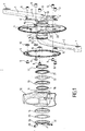
- the figure 1 shows a cycle pedal according to the invention comprising a first crank 1 connected to a second crank 2 by a crank axle 3.
- the cranks 1 and 2 extend in opposite directions from a respective end of the crankset shaft 3.
- the cranks 1 and 2 are capable of carrying at their end a respective pedal (not shown) whose threaded axis can be screwed into a threaded hole 7 at the end of the crank.
- the crankset comprises two large pinions consisting of a first circular toothed plate 4 and a second circular toothed plate 5 fixed to a star-shaped tray holder 6 integral in rotation with the bottom bracket shaft 3.
- the teeth of the first and second plates 4, 5 are able to cooperate with a drive chain (not shown) which in turn rotates the rear wheel (not shown) of a cycle.
- This pedal cycle is thus double trays, that is to say it comprises a first toothed plate 4 which is larger than the second toothed plate 5 for obtaining a large development for the use of the cycle downhill or plain, while the second plate 5, smaller, makes it easier to climb the ribs or start more easily.
- the first and second trays 4, 5 are fixed on the branches 6 'of the tray holder 6 by means of fixing means such as screws 8 which pass through holes provided in the trays and in the tray holder to cooperate with nuts 9, with the interposition of spacers 10 between the first and second plates.
- the bottom bracket shaft 3 is adapted to be housed in a bottom bracket 11 of a cycle frame 12, of which only the part concerned by the invention is shown in the figures.
- a first bearing 13 and a second bearing 14 connect the bottom bracket to the bottom bracket tube being arranged around the bottom bracket axis near the ends thereof. This arrangement will be described in detail later.
- the first and second cranks 1, 2 and the crank axis 3 are made of a composite material. According to another aspect of the invention, the first and second cranks 1, 2 and the crank axis 3 are made of a hollow light alloy, for example formed by hydroforming.
- a first and second intermediate rings 15, 16 made of a high rigidity and abrasion resistant material are fixed on the bottom bracket shaft 3 near a respective end thereof to receive in tight connection a respective bearing 13, 14.
- the high rigidity and abrasion resistant material of the first and second intermediate rings 15, 16 is preferably a light alloy having the characteristics necessary to withstand abrasion.
- the intermediate rings 15, 16 may be fixed to the bottom bracket shaft 3 by gluing or, very advantageously, in the case where the material of the one-piece crankset is a composite material, they may be fixed thereto by the polymerization of the composite material of the pedal axle following an expansion of the material which can for example be obtained by inflation with compressed air.
- the intermediate rings 15, 16 can be fixed on the crankset 3 during the manufacture of the crankset monobloc, and more precisely the rings 15, 16 are during manufacture set up on the bottom bracket to be fixed by the expansion of the alloy during hydroforming.
- the tray holder 6 is part of the integral part formed by the cranks 1, 2 and the bottom bracket 3.
- the branches 6 'of the tray carrier 6 originate directly on the end of the first crank 1 connected to the bottom bracket 3, being centered on the axis AA thereof.
- crankset with the crankset 11 of the frame 12 are illustrated on the figure 1 .
- the first bearing 13 is immobilized on the crank axle 3 by means of two stop rings 17, 18 disposed on either side of the bearing 13 and entering corresponding grooves 19, 20 provided on the axle. of bottom bracket.
- a washer 21 and a seal 22 are placed between the bearing 13 and the stop ring 17 on the side of the tray holder 6. In this way is obtained a subassembly held in place during assembly.
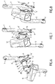
- the second bearing 14 is fixed inside the bottom bracket tube 11 against a first circular abutment rib 23, as illustrated in FIG. figure 3 .
- a second circular abutment rib 24 is provided in the bottom bracket tube 11, against which the first bearing 13 must then be supported.
- a seal 25 is in the assembly placed against the outer face of the second bearing 14 and the whole assembly is held in place by means of an assembly ring 26 which has a tapping 27 fit to cooperate with a thread 28 provided on the second intermediate ring 16, the side of the outer edge thereof.
- the connecting ring 26 is preferably slotted so that its screwing on the threading 28 is facilitated by the introduction of a shim 29 into the slot 30 of the ring which keeps it spaced at the right size and it is then easy to screw the assembly ring 26 onto the thread 28 of the second intermediate ring 16, until a free assembly is obtained without excessive play.
- the figure 5 shows the last phase of this assembly after which the shim 29 is removed after this adjustment, while the figure 4 shows the relative position of the parts assembled on the bottom bracket 3.
- the assembly ring 26 advantageously has a fixing hole 31 extending perpendicularly to the slot 30 of the ring 26 on either side of it to receive a fastening and clamping screw 32.
- the fixing hole 31 is preferably threaded to cooperate directly with the thread of the screw 32.
- the bottom bracket shaft 3 advantageously has a concave central recess 33 so that it does not interfere. assembly of the pedal with the frame. This recess 33 can be combined with a round convex conformation 34 on the nascent part of the second crank 2.
- Figures 6 to 8 illustrate three consecutive phases of the assembly of the crankset according to the invention on a cycle frame.
Description
La présente invention concerne un pédalier de cycle, et en particulier un pédalier monobloc, ainsi qu'un cycle pourvu d'un tel pédalier.The present invention relates to a cycle pedal, and in particular a monobloc pedals, and a cycle provided with such a pedal.
Les pédaliers de cycle comportent un axe de pédalier, deux manivelles fixées aux extrémités de l'axe, et un grand pignon solidaire en rotation de l'axe de pédalier. Les manivelles s'étendent dans des sens opposés et comportent à leur extrémité libre des moyens de fixation d'un axe de pédale. Ces moyens de fixation sont en général constitués par un simple trou taraudé recevant l'extrémité filetée de l'axe de pédale.The cycle cranks include a crank axle, two cranks fixed to the ends of the axle, and a large pinion integral in rotation with the crank axle. The cranks extend in opposite directions and comprise at their free end means for fixing a pedal axle. These fixing means are generally constituted by a simple tapped hole receiving the threaded end of the pedal shaft.
L'axe de pédalier est apte à être reçu dans un tube de pédalier d'un cadre de cycle avec interposition de roulements disposés aux extrémités de l'axe de pédalier et formant ainsi un moyeu permettant la rotation de l'axe de pédalier à l'intérieur du tube de pédalier.The crank axle is adapted to be received in a bottom bracket of a cycle frame with the interposition of bearings arranged at the ends of the bottom bracket axle and thus forming a hub allowing the rotation of the bottom bracket axis at the bottom. inside the bottom bracket tube.
Il existe des pédaliers de cycle monobloc, entre autres destinés à l'obtention d'une meilleure précision de l'emplacement relatif des parties différentes d'un pédalier de cycle. Dans un pédalier monobloc classique, l'axe de pédalier et les deux manivelles forment ensemble une seule pièce en métal qui présente globalement la forme d'un "Z".There are one-piece cycle cranks, among others intended to obtain a better accuracy of the relative location of the different parts of a cycle pedal. In a conventional one-piece crankset, the crank axle and the two cranks together form a single piece of metal which generally has the shape of a "Z".
Un tel pédalier de cycle monobloc est connu du brevet
Un pédalier de cycle monobloc selon le préambule de la revendication 1 est décrit dans le brevet
La tendance générale étant de rendre tous les composants d'un cycle aussi légers que possible tout en assurant une bonne tenue mécanique, il serait avantageux de pouvoir utiliser un pédalier monobloc entièrement en matériau composite. Cependant, le carbone, peu résistant à l'abrasion, rend pratiquement impossible un appui direct des roulements qui en outre doivent parfois être démontés et remplacés pour les opérations de maintenance.The general trend is to make all the components of a cycle as light as possible while ensuring a good mechanical strength, it would be advantageous to be able to use a one-piece crankset made entirely of composite material. However, carbon, which is not very resistant to abrasion, makes it almost impossible to provide direct support for the bearings, which must sometimes be dismantled and replaced for maintenance operations.
Pour cette raison, tout en souhaitant une structure allégée à l'aide de matériaux composites, on a jusqu'à ce jour été obligé de se limiter à des pédaliers de cycle en plusieurs parties dont principalement les manivelles sont en matériaux composites. Cependant, il est dans ce cas inévitable d'utiliser des inserts métalliques dans les extrémités pour assurer une bonne fixation des manivelles sur l'axe de pédalier, le plus souvent à l'aide de cannelures. Le souhait est de rendre l'ensemble moins lourd, mais les inserts ajoutent nécessairement du poids, entraînent un surcoût de fabrication et rendent le pédalier complexe pour garantir une bonne tenue mécanique.For this reason, while wishing a lightweight structure using composite materials, it has until now been forced to be limited to multi-part cycle pedals whose mainly cranks are made of composite materials. However, it is in this case inevitable to use metal inserts in the ends to ensure proper attachment of the cranks on the bottom bracket, usually with splines. The desire is to make the set less heavy, but the inserts necessarily add weight, lead to additional manufacturing costs and make the pedal complex to ensure good mechanical strength.
Une autre solution pour rendre le pédalier de cycle plus léger consisterait à utiliser un alliage léger creux, mais jusqu'ici on s'est également limité à des pédaliers de cycle en plusieurs parties dont principalement les manivelles sont en un alliage léger creux. Un tel pédalier est connu du document
Cette limitation est probablement dû au fait qu'un pédalier de cycle monobloc d'un seul tenant en un alliage creux poserait le problème de la rigidité des parois minces de l'axe de pédalier qui à l'endroit de l'emplacement des roulements risqueraient de se déformer sous les efforts. Pour cette raison, un pédalier de cycle monobloc de ce genre n'a pas encore été envisagé.This limitation is probably due to the fact that a one-piece monobloc cycle crankset made of a hollow alloy would pose the problem of the rigidity of the thin walls of the bottom bracket which at the location of the location of the bearings could deform under effort. For this reason, a one-piece cycle crankset of this kind has not yet been considered.
Le but de l'invention est de remédier à ces inconvénients en proposant une solution permettant l'utilisation d'un pédalier de cycle monobloc en un matériau composite ou en un alliage léger creux afin d'alléger notablement l'ensemble du pédalier. Dans le premier cas, il est possible de supprimer un nombre important de pièces de liaison comme vis, écrous ou rondelles, ainsi que les inserts correspondants. Dans le deuxième cas, la nouvelle conception apporte une rigidité améliorée de tout l'ensemble et permet d'utiliser le maximum du volume disponible en même temps que les parois peuvent être rendues relativement minces pour maintenir un poids réduit.The object of the invention is to overcome these disadvantages by proposing a solution allowing the use of a monobloc cycle crankset of a composite material or a light hollow alloy in order to significantly lighten the entire crankset. In the first case, it is possible to remove a large number of connecting pieces such as screws, nuts or washers, as well as the corresponding inserts. In the second case, the new design provides improved rigidity of the whole assembly and allows to use the maximum volume available at the same time that the walls can be made relatively thin to maintain a reduced weight.
L'objet de l'invention est un pédalier de cycle monobloc, comportant une première manivelle reliée à une deuxième manivelle par un axe de pédalier en formant avec celui-ci une pièce d'un seul tenant, l'axe de pédalier étant apte à être logé dans un tube de pédalier d'un cadre de cycle avec interposition d'un premier roulement et d'un deuxième roulement disposés autour de l'axe de pédalier à proximité des extrémités de celui-ci afin de permettre la rotation de l'axe de pédalier à l'intérieur dudit tube de pédalier, un grand pignon d'entraînement d'une chaîne étant disposé à proximité de l'une des extrémités de l'axe de pédalier et solidaire en rotation avec celui-ci, une première et une deuxième bagues intermédiaires en un matériau à rigidité élevée et résistant à l'abrasion étant fixées sur l'axe de pédalier à proximité d'une extrémité respective de celui-ci pour recevoir un roulement respectif, caractérisé par le fait que lesdites bagues intermédiaires sont fixées sur l'axe de pédalier par polymérisation dudit matériau composite de l'axe de pédalier suite à une expansion dudit matériau.The object of the invention is a one-piece cycle crankset, comprising a first crank connected to a second crank by a crank axle forming with it a piece in one piece, the crank axis being adapted to being accommodated in a pedal tube of a cycle frame with the interposition of a first bearing and a second bearing arranged around the bottom bracket axis near the ends thereof to allow rotation of the crank axle within said bottom bracket tube, a large chain drive sprocket being disposed near one end of the crank axle and rotatably connected therewith, a first and a second intermediate ring made of a material with high rigidity and abrasion resistant being fixed on the bottom bracket axis near a respective end thereof to receive a respective bearing, characterized in that said brackets intermediates are fixed on the bottom bracket axle by polymerization of said composite material of the bottom bracket axle following a expanding said material.
Selon d'autres caractéristiques de l'invention :
- le matériau du pédalier est un matériau composite ;
- le matériau du pédalier est un alliage léger creux ;
- lesdites bagues intermédiaires sont fixées sur l'axe de pédalier par l'expansion de l'alliage lors du formage du pédalier ;
- ladite bague intermédiaire la plus éloignée du grand pignon est sur son extrémité dirigée vers l'extérieur pourvue d'un filetage apte à coopérer avec une bague d'assemblage taraudée ;
- ladite bague d'assemblage est fendue afin de recevoir dans sa fente une cale d'épaisseur facilitant lors de l'assemblage le vissage de la bague d'assemblage sur le filetage de la bague intermédiaire ;
- ladite bague d'assemblage comporte un trou de fixation s'étendant perpendiculairement à la fente de la bague d'assemblage de part et d'autre de celle-ci pour recevoir une vis de fixation et de serrage ;
- l'axe de pédalier présente un évidement central concave facilitant l'assemblage du pédalier avec le cadre ;
- ledit grand pignon est constitué par un plateau denté circulaire porté par un porte-plateau, et ledit porte-plateau fait partie de ladite une pièce d'un seul tenant ;
- le porte-plateau est en forme d'étoile dont les branches prennent naissance directement sur l'extrémité de la première manivelle reliée à l'axe de pédalier en étant centrées sur l'axe A-A de celui-ci ;
- ledit premier roulement est immobilisé sur l'axe de pédalier à l'aide de deux bagues d'arrêt disposées de part et d'autre du roulement et entrant dans des gorges correspondantes prévues sur l'axe de pédalier ;
- le matériau à rigidité élevée et résistant à l'abrasion des première et deuxième bagues intermédiaires est un alliage léger.
- the material of the crankset is a composite material;
- the material of the crankset is a light hollow alloy;
- said intermediate rings are fixed on the crank axle by the expansion of the alloy during the forming of the crankset;
- said intermediate ring farthest from the large pinion is on its end directed outwardly provided with a thread adapted to cooperate with a threaded connecting ring;
- said connecting ring is slotted to receive in its slot a spacer having a thickness facilitating assembly of the screwing of the assembly ring on the thread of the intermediate ring;
- said assembly ring has a fixing hole extending perpendicularly to the slot of the connecting ring on either side thereof to receive a fastening screw and clamping;
- the crank axle has a concave central recess facilitating the assembly of the pedal with the frame;
- said large pinion is constituted by a circular toothed tray carried by a tray holder, and said tray holder is part of said one piece in one piece;
- the tray holder is star-shaped whose branches originate directly on the end of the first crank connected to the bottom bracket axis being centered on the axis AA thereof;
- said first bearing is immobilized on the bottom bracket axis by means of two stop rings disposed on either side of the bearing and entering corresponding grooves provided on the bottom bracket axle;
- the high rigidity and abrasion resistant material of the first and second intermediate rings is a light alloy.
Un autre objet de l'invention est un cycle pourvu d'un pédalier tel que défini ci-dessus.Another object of the invention is a cycle provided with a pedal as defined above.
D'autres caractéristiques et avantages de l'invention ressortiront de la description qui va suivre d'un mode de réalisation non limitatif de l'invention, en référence aux figures annexées dans lesquelles :
- la
figure 1 est une vue en perspective éclatée d'un pédalier de cycle monobloc selon l'invention ; - la
figure 2 est une vue partielle en perspective du pédalier de cycle avec un sous-ensemble préassemblé avant son assemblage sur un tube de pédalier d'un cadre de cycle ; - la
figure 3 est une vue partielle en perspective d'un tube de pédalier préparé avec la mise en place d'un roulement avant de recevoir le pédalier de cycle de lafigure 2 ; - la
figure 4 est une vue partielle en coupe selon la ligne A-A de lafigure 2 ; - la
figure 5 est une vue partielle en perspective illustrant la dernière phase de l'assemblage du pédalier de cycle avec le tube de pédalier de lafigure 3 ; - les
figures 6 à 8 montrent trois phases consécutives de l'assemblage du pédalier de cycle avec le tube de pédalier.
- the
figure 1 is an exploded perspective view of a one-piece cycle crankset according to the invention; - the
figure 2 is a partial perspective view of the cycle crank with a preassembled subassembly prior to assembly on a bottom bracket tube of a cycle frame; - the
figure 3 is a partial perspective view of a pedal tube prepared with the introduction of a bearing before receiving the pedal cycle of thefigure 2 ; - the
figure 4 is a partial sectional view along line AA of thefigure 2 ; - the
figure 5 is a partial perspective view illustrating the last phase of the assembly of the cycle crankset with the bottom bracket tube of thefigure 3 ; - the
Figures 6 to 8 show three consecutive phases of assembly of the cycle crankset with the bottom bracket tube.
Dans les figures, les éléments identiques ou équivalents porteront les mêmes signes de référence.In the figures, identical or equivalent elements will bear the same reference signs.
La
Dans l'exemple illustré, le pédalier comporte deux grands pignons constitués par un premier plateau denté circulaire 4 et un deuxième plateau denté circulaire 5 fixés sur un porte-plateau 6 en forme d'étoile solidaire en rotation de l'axe de pédalier 3. Les dents des premier et deuxième plateaux 4, 5 sont aptes à coopérer avec une chaîne d'entraînement (non représentée) qui à son tour entraîne en rotation la roue arrière (non représentée) d'un cycle.In the illustrated example, the crankset comprises two large pinions consisting of a first circular toothed plate 4 and a second circular
Ce pédalier de cycle est ainsi à plateaux doubles, c'est-à-dire qu'il comporte un premier plateau denté 4 qui est plus grand que le deuxième plateau denté 5 pour l'obtention d'un grand développement pour l'utilisation du cycle en descente ou en plaine, alors que le deuxième plateau 5, plus petit, permet de monter plus facilement les côtes ou de démarrer plus aisément.This pedal cycle is thus double trays, that is to say it comprises a first toothed plate 4 which is larger than the second
Les premier et deuxième plateaux 4, 5 sont fixés sur les branches 6' du porte-plateau 6 à l'aide de moyens de fixation tels que des vis 8 qui traversent des trous prévus dans les plateaux et dans le porte-plateau pour coopérer avec des écrous 9, avec interposition d'entretoises 10 entre les premier et deuxième plateaux.The first and
L'axe de pédalier 3 est apte à être logé dans un tube de pédalier 11 d'un cadre de cycle 12 dont seulement la partie concernée par l'invention est montrée sur les figures. Afin de permettre la rotation de l'axe de pédalier 3 à l'intérieur du tube de pédalier 11, un premier roulement 13 et un deuxième roulement 14 relient l'axe de pédalier au tube de pédalier en étant disposés autour de l'axe de pédalier à proximité des extrémités de celui-ci. Ce montage sera décrit en détail plus loin.The
Selon un aspect de l'invention, les première et deuxième manivelles 1, 2 ainsi que l'axe de pédalier 3 sont en un matériau composite. Selon un autre aspect de l'invention, les première et deuxième manivelles 1, 2 ainsi que l'axe de pédalier 3 sont en un alliage léger creux, par exemple formé par hydroformage.According to one aspect of the invention, the first and
Selon une caractéristique essentielle de l'invention, une première et deuxième bagues intermédiaires 15, 16 en un matériau à rigidité élevée et résistant à l'abrasion sont fixées sur l'axe de pédalier 3 à proximité d'une extrémité respective de celui-ci pour recevoir en liaison serrée un roulement respectif 13, 14.According to an essential characteristic of the invention, a first and second
Afin d'alléger davantage l'ensemble, le matériau à rigidité élevée et résistant à l'abrasion des première et deuxième bagues intermédiaires 15, 16 est de préférence un alliage léger présentant les caractéristiques nécessaires pour bien résister à l'abrasion.To further lighten the assembly, the high rigidity and abrasion resistant material of the first and second
Les bagues intermédiaires 15, 16 peuvent être fixées sur l'axe de pédalier 3 par collage ou, très avantageusement, dans le cas où le matériau du pédalier monobloc est un matériau composite, elles peuvent y être fixées par la polymérisation du matériau composite de l'axe de pédalier suite à une expansion du matériau qui peut par exemple être obtenue par gonflage avec de l'air comprimé.The intermediate rings 15, 16 may be fixed to the
D'une manière analogue dans le cas où le matériau du pédalier monobloc est un alliage léger, les bagues intermédiaires 15, 16 peuvent être fixées sur l'axe de pédalier 3 lors de la fabrication du pédalier monobloc, et plus précisément les bagues 15, 16 sont lors de la fabrication mises en place sur l'axe de pédalier pour être fixées par l'expansion de l'alliage lors de l'hydroformage.In a similar way in the case where the material of the one-piece crankset is a light alloy, the
Selon une autre caractéristique importante de l'invention, le porte-plateau 6 fait partie de la pièce d'un seul tenant formée par les manivelles 1, 2 et l'axe de pédalier 3. Dans le mode de réalisation illustré sur les figures, les branches 6' du porte-plateau 6 prennent naissance directement sur l'extrémité de la première manivelle 1 reliée à l'axe de pédalier 3, en étant centrées sur l'axe A-A de celui-ci.According to another important feature of the invention, the
D'autres éléments utilisés pour l'assemblage du pédalier avec le tube du pédalier 11 du cadre 12 sont illustrés sur la
Ainsi, pour l'assemblage il est avantageux de fixer au préalable le premier roulement 13 sur l'axe de pédalier 3 (voir
Le premier roulement 13 est immobilisé sur l'axe de pédalier 3 à l'aide de deux bagues d'arrêt 17, 18 disposées de part et d'autre du roulement 13 et entrant dans des gorges correspondantes 19, 20 prévues sur l'axe de pédalier. Une rondelle 21 et un joint d'étanchéité 22 sont placés entre le roulement 13 et la bague d'arrêt 17 du côté du porte-plateau 6. De cette manière est obtenu un sous-ensemble maintenu en place lors de l'assemblage.The
Le deuxième roulement 14 est fixé à l'intérieur du tube de pédalier 11 contre une première nervure circulaire de butée 23, comme cela est illustré à la
Finalement, un joint d'étanchéité 25 est lors de l'assemblage placé contre la face extérieure du deuxième roulement 14 et tout l'ensemble est maintenu en place à l'aide d'une bague d'assemblage 26 qui comporte un taraudage 27 apte à coopérer avec un filetage 28 prévu sur la deuxième bague intermédiaire 16, du côté du bord extérieur de celle-ci.Finally, a
La bague d'assemblage 26 est de préférence fendue pour que son vissage sur le filetage 28 soit facilité par l'introduction d'une cale d'épaisseur 29 dans la fente 30 de la bague qui maintient celle-ci écartée à la bonne dimension et on peut alors facilement visser la bague d'assemblage 26 sur le filetage 28 de la deuxième bague intermédiaire 16, jusqu'à l'obtention d'un assemblage libre mais sans jeu excessif.The connecting
La
La bague d'assemblage 26 comporte pour son maintien fiable avantageusement un trou de fixation 31 s'étendant perpendiculairement à la fente 30 de la bague 26 de part et d'autre de celle-ci pour recevoir une vis de fixation et de serrage 32. Le trou de fixation 31 est de préférence taraudé pour coopérer directement avec le filetage de la vis 32.The
Pour faciliter l'introduction et le déplacement de l'axe de pédalier 3 à l'intérieur du tube de pédalier 11 lors de l'assemblage, l'axe de pédalier 3 présente avantageusement un évidement central concave 33 pour qu'il ne gêne pas à l'assemblage du pédalier avec le cadre. Cet évidement 33 peut être combiné avec une conformation arrondie convexe 34 sur la partie naissante de la deuxième manivelle 2.To facilitate the introduction and movement of the
Finalement, les
Bien entendu, l'invention n'est pas limitée aux exemples illustrés et décrits, et il est à la portée de l'homme du métier de prévoir de nombreuses variantes sans pour autant sortir du cadre de l'invention.Of course, the invention is not limited to the examples illustrated and described, and it is within the abilities of those skilled in the art to provide numerous variants without departing from the scope of the invention.
Claims (12)
- A one-piece cycle crankset, including a first crank (1) connected to a second crank (2) through a crankset axis (3), forming with the latter, a one-piece part, the crankset axis (3) being able to be housed in a crankset tube (11) of a cycle frame (12) with interposition of a first bearing (13) and of a second bearing (14) positioned around the crankset axis (3) near the ends of the latter in order to allow rotation of the crankset axis inside said crankset tube (11), a large gear wheel (4,5) for driving a chain being positioned near one of the ends of the crankset axis (3) and interdependent in rotation with the latter, first and second intermediate rings (15, 16) in a high rigidity and abrasion-resistant material being attached onto the crankset axis (3) near a respective end of the latter in order to receive a respective bearing (13, 14), characterized by the fact that the material of the crankset is a composite material and that said intermediate rings (15, 16) are attached onto the crankset axis (3) by polymerization of said composite material of the crankset axis following expansion of said material.
- The one-piece cycle crankset according to claim 1, characterized by the fact that the material of the crankset is a hollow lightweight alloy.
- The one-piece cycle crankset according to claim 2, characterized by the fact that said intermediate rings (15, 16) are attached on the crankset axis (3) by expansion of the alloy upon forming the crankset.
- The one-piece cycle crankset according to any of the preceding claims, characterized by the fact that said intermediate ring (16), the farthest away from the large gear wheel (4, 5) is, on its outward-oriented end, provided with a threading (28) capable of cooperating with a tapped assembling ring (26).
- The one-piece cycle crankset according to claim 4, characterized by the fact that said assembling ring (26) is slotted in order to receive in its slot (30), a thickness shim (29) facilitating, during the assembling, the screwing of the assembling ring (26) onto the threading (28) of said intermediate ring (16).
- The one-piece cycle crankset according to claim 5, characterized by the fact that said assembling ring (26) includes an attachment hole (31) extending perpendicularly to the slot (30) of the assembling ring (26) on either side of the latter for receiving a fixing and tightening screw (32).
- The one-piece cycle crankset according to any of the preceding claims, characterized by the fact that the crankset axis (3) has a concave central recess (33) facilitating the assembling of the crankset with the frame.
- The one-piece cycle crankset according to any of the preceding claims, wherein said large gear wheel (4, 5) is formed by a circular toothed plate borne by a plate-holder (6), characterized by the fact that said plate-holder (6) is part of said single one-piece part (1, 2, 3).
- The one-piece cycle crankset according to claim 8, characterized by the fact that the plate-holder (6) is star-shaped, the branches (6') of which originate directly on the end of the first crank (1) connected to the crankset axis (3), while being centered on the axis (A-A) of the latter.
- The one-piece cycle crankset according to any of the preceding claims, characterized by the fact that said first bearing (13) is immobilized on the crankset axis (3) by means of two locating rings (17, 18) positioned on either side of the bearing (13) and entering matching grooves (19, 20) provided on the crankset axis (3).
- The one-piece cycle crankset according to any of the preceding claims, characterized by the fact that the high rigidity and abrasion-resistant material of the first and second intermediate rings (15, 16) is a lightweight alloy.
- A cycle with a one-piece cycle crankset, characterized by the fact that the crankset has characteristics of any of claims 1 to 11.
Applications Claiming Priority (1)
| Application Number | Priority Date | Filing Date | Title |
|---|---|---|---|
| FR0804195A FR2934239B1 (en) | 2008-07-23 | 2008-07-23 | MONOBLOC CYCLE PEDAL |
Publications (2)
| Publication Number | Publication Date |
|---|---|
| EP2148105A1 EP2148105A1 (en) | 2010-01-27 |
| EP2148105B1 true EP2148105B1 (en) | 2012-12-26 |
Family
ID=40138385
Family Applications (1)
| Application Number | Title | Priority Date | Filing Date |
|---|---|---|---|
| EP09305549A Active EP2148105B1 (en) | 2008-07-23 | 2009-06-16 | Single-piece cycle crankset |
Country Status (5)
| Country | Link |
|---|---|
| US (1) | US20100018345A1 (en) |
| EP (1) | EP2148105B1 (en) |
| CN (1) | CN101633389B (en) |
| FR (1) | FR2934239B1 (en) |
| TW (1) | TW201012705A (en) |
Families Citing this family (3)
| Publication number | Priority date | Publication date | Assignee | Title |
|---|---|---|---|---|
| TW201223823A (en) * | 2011-10-07 | 2012-06-16 | li-he Yao | Torque sensing device for power assisting bicycle |
| CN104828201A (en) * | 2015-05-19 | 2015-08-12 | 天津市兴轮生产力促进有限公司 | Integrally formed bicycle chain wheel |
| CN109722381A (en) * | 2019-03-05 | 2019-05-07 | 南华大学 | Device and method for microculture and growth monitoring |
Family Cites Families (29)
| Publication number | Priority date | Publication date | Assignee | Title |
|---|---|---|---|---|
| US529110A (en) * | 1894-11-13 | Crank-shaft and bearing for velocipedes | ||
| US604710A (en) * | 1898-05-24 | James r | ||
| US552376A (en) * | 1895-12-31 | William h | ||
| US1449235A (en) * | 1921-06-08 | 1923-03-20 | Mead Cycle Company | Crank-hanger assembly |
| US3551004A (en) * | 1968-11-19 | 1970-12-29 | American Mach & Foundry | Bicycle improvement |
| JPS5943189Y2 (en) | 1980-06-11 | 1984-12-20 | 株式会社シマノ | Bicycle gear crank device |
| US4552468A (en) * | 1982-02-17 | 1985-11-12 | Hopper Jr Willard C | Bicycle sealed bearing kit |
| US4545691A (en) * | 1983-07-18 | 1985-10-08 | B. Linn Kastan | Bicycle crank bearing assembly |
| US4602524A (en) * | 1984-11-19 | 1986-07-29 | General Signal Corporation | Method of manufacturing bicycle chain drives |
| US4704919A (en) * | 1984-11-28 | 1987-11-10 | Durham Roger O | Two-piece crankshaft for bicycles |
| CN2052744U (en) * | 1989-08-23 | 1990-02-14 | 于金祥 | High gear ratio transmision device for bicycle |
| US5493937A (en) * | 1993-08-23 | 1996-02-27 | Edwards; Craig H. | Light-weight bicycle crankshaft assembly utilizing two-piece axle integrally joined to crank arms |
| US6116114A (en) * | 1993-08-23 | 2000-09-12 | Edwards; Craig H. | Rotatable spindle assembly utilizing two-piece spindle |
| JP3149374B2 (en) | 1996-12-27 | 2001-03-26 | 株式会社シマノ | Bicycle hollow crank and manufacturing method thereof |
| US6443033B1 (en) * | 1997-04-11 | 2002-09-03 | Timothy Eugene Brummer | Two-piece bicycle crankset |
| US5941135A (en) * | 1997-06-18 | 1999-08-24 | Schlanger; Raphael | Bicycle crankshaft assembly |
| US6829965B1 (en) * | 1999-05-28 | 2004-12-14 | Bruno Mombrinie | Two-piece bicycle crank set |
| US6164157A (en) * | 1999-07-14 | 2000-12-26 | Chen; Hsing-Lung | Bicycle crankset |
| US6264226B1 (en) * | 2000-02-07 | 2001-07-24 | Chu-Chan Chang | Pedal crank structure of children's bike |
| ITTO20010617A1 (en) * | 2001-06-27 | 2002-12-27 | Campagnolo Srl | CRANK FOR BICYCLE AND PROCEDURE FOR ITS MANUFACTURE. |
| CN2559552Y (en) * | 2001-09-12 | 2003-07-09 | 王新疆 | Chain transmission mechanism for bicycle |
| EP1486412B1 (en) * | 2003-06-10 | 2014-05-07 | Campagnolo S.R.L. | Bicycle pedal crank |
| JP2006046501A (en) * | 2004-08-04 | 2006-02-16 | Yamamoto Seisakusho:Kk | Bearing structure |
| US7784378B2 (en) * | 2004-11-17 | 2010-08-31 | Raphael Schlanger | Bicycle crank assembly |
| DE102005022808A1 (en) * | 2005-05-12 | 2006-11-16 | Frank Weidner | Safety device for steering head bearings and method for securing steering head bearings |
| EP1749736A1 (en) * | 2005-08-03 | 2007-02-07 | Campagnolo S.R.L. | Bicycle component of composite material with inserts and relative manufacturing process |
| US20070295157A1 (en) * | 2006-06-27 | 2007-12-27 | Specialized Bicycle Components, Inc. | Crankset assembly for a bicycle |
| US7650818B2 (en) * | 2007-03-30 | 2010-01-26 | Shimano Inc. | Bicycle shaft component |
| US20090056496A1 (en) * | 2007-09-04 | 2009-03-05 | Dodman Christopher P | Composite Crank Assembly |
-
2008
- 2008-07-23 FR FR0804195A patent/FR2934239B1/en not_active Expired - Fee Related
-
2009
- 2009-06-16 EP EP09305549A patent/EP2148105B1/en active Active
- 2009-07-20 US US12/505,559 patent/US20100018345A1/en not_active Abandoned
- 2009-07-21 TW TW098124510A patent/TW201012705A/en unknown
- 2009-07-23 CN CN2009101604737A patent/CN101633389B/en active Active
Also Published As
| Publication number | Publication date |
|---|---|
| TW201012705A (en) | 2010-04-01 |
| US20100018345A1 (en) | 2010-01-28 |
| FR2934239A1 (en) | 2010-01-29 |
| FR2934239B1 (en) | 2010-08-20 |
| EP2148105A1 (en) | 2010-01-27 |
| CN101633389B (en) | 2013-01-02 |
| CN101633389A (en) | 2010-01-27 |
Similar Documents
| Publication | Publication Date | Title |
|---|---|---|
| EP0270388B1 (en) | Pedal crank for a bicycle | |
| EP1780113B1 (en) | Automatic pedal with arc shaped cleat fastener | |
| FR2614596A1 (en) | BICYCLE PEDAL | |
| EP1741943B2 (en) | Bearing arrangement for power transmission of a wind turbine | |
| EP2849992B1 (en) | Bicycle handlebar stem with adjustable inclination | |
| FR2893303A1 (en) | CYCLE PEDAL | |
| WO2020144419A1 (en) | Electric assist device for a bicycle | |
| EP2148105B1 (en) | Single-piece cycle crankset | |
| WO2020144411A2 (en) | Reduction gear | |
| FR2629958A1 (en) | ROTOR FOR ELECTRIC MACHINE EXCITED BY PERMANENT MAGNETS | |
| CH257924A (en) | Hub for rear wheel of cycles. | |
| FR2855099A1 (en) | Lightweight hub for bicycle or similar vehicle has the hub supported on a lightweight tube with end fittings to secure the bearings and to connect to the forks | |
| FR2910866A1 (en) | Support device for motor vehicle, has single block part with tubular section body, guide bearing guiding rotative axle of windscreen wiper mechanism, and fixation points with carrier structure, where device is made of plastic material | |
| EP0229958A1 (en) | Speed-reducing gear | |
| FR2707559A1 (en) | Improvement to a wheel designed to equip cycles | |
| EP0403714B1 (en) | Vehicle transmission with electric retarders | |
| EP2879943B1 (en) | Bicycle convertible into a hobby horse | |
| FR2843364A1 (en) | Cycle pedal gear comprises two crank supports eccentrically positioned on driving cog rotational axis, rotation of cranks carrying pedals transmitted to driving cog by lugs on cranks displacing in runners connected to driving cog axis | |
| EP4008929B1 (en) | Satellite assembly, epicyclic gearset provided with such an assembly and power transmission unit | |
| FR2649049A1 (en) | IMPROVEMENTS IN TRANSMISSIONS OF VEHICLES EQUIPPED WITH ELECTRIC RETARDERS | |
| EP2186990B1 (en) | Actuator for roll-up concealing screen | |
| FR3054521A1 (en) | CYCLE EQUIPPED WITH AN ELECTRICAL ASSISTANCE MODULE, AND ELECTRICAL ASSISTANCE MODULE FOR SUCH A CYCLE | |
| WO2004108514A1 (en) | Device for fixing a bicycle wheel to a frame | |
| WO2019192789A1 (en) | Mechanical gearbox for machine farming machine, and corresponding assembly method | |
| FR3140303A1 (en) | reinforced vehicle wheel |
Legal Events
| Date | Code | Title | Description |
|---|---|---|---|
| PUAI | Public reference made under article 153(3) epc to a published international application that has entered the european phase |
Free format text: ORIGINAL CODE: 0009012 |
|
| AK | Designated contracting states |
Kind code of ref document: A1 Designated state(s): AT BE BG CH CY CZ DE DK EE ES FI FR GB GR HR HU IE IS IT LI LT LU LV MC MK MT NL NO PL PT RO SE SI SK TR |
|
| AX | Request for extension of the european patent |
Extension state: AL BA RS |
|
| 17P | Request for examination filed |
Effective date: 20100615 |
|
| 17Q | First examination report despatched |
Effective date: 20111220 |
|
| GRAP | Despatch of communication of intention to grant a patent |
Free format text: ORIGINAL CODE: EPIDOSNIGR1 |
|
| GRAS | Grant fee paid |
Free format text: ORIGINAL CODE: EPIDOSNIGR3 |
|
| GRAA | (expected) grant |
Free format text: ORIGINAL CODE: 0009210 |
|
| AK | Designated contracting states |
Kind code of ref document: B1 Designated state(s): AT BE BG CH CY CZ DE DK EE ES FI FR GB GR HR HU IE IS IT LI LT LU LV MC MK MT NL NO PL PT RO SE SI SK TR |
|
| REG | Reference to a national code |
Ref country code: GB Ref legal event code: FG4D Free format text: NOT ENGLISH |
|
| REG | Reference to a national code |
Ref country code: CH Ref legal event code: EP |
|
| REG | Reference to a national code |
Ref country code: AT Ref legal event code: REF Ref document number: 590650 Country of ref document: AT Kind code of ref document: T Effective date: 20130115 |
|
| REG | Reference to a national code |
Ref country code: DE Ref legal event code: R096 Ref document number: 602009012211 Country of ref document: DE Effective date: 20130307 |
|
| PG25 | Lapsed in a contracting state [announced via postgrant information from national office to epo] |
Ref country code: LT Free format text: LAPSE BECAUSE OF FAILURE TO SUBMIT A TRANSLATION OF THE DESCRIPTION OR TO PAY THE FEE WITHIN THE PRESCRIBED TIME-LIMIT Effective date: 20121226 Ref country code: SE Free format text: LAPSE BECAUSE OF FAILURE TO SUBMIT A TRANSLATION OF THE DESCRIPTION OR TO PAY THE FEE WITHIN THE PRESCRIBED TIME-LIMIT Effective date: 20121226 Ref country code: HR Free format text: LAPSE BECAUSE OF FAILURE TO SUBMIT A TRANSLATION OF THE DESCRIPTION OR TO PAY THE FEE WITHIN THE PRESCRIBED TIME-LIMIT Effective date: 20121226 Ref country code: FI Free format text: LAPSE BECAUSE OF FAILURE TO SUBMIT A TRANSLATION OF THE DESCRIPTION OR TO PAY THE FEE WITHIN THE PRESCRIBED TIME-LIMIT Effective date: 20121226 Ref country code: NO Free format text: LAPSE BECAUSE OF FAILURE TO SUBMIT A TRANSLATION OF THE DESCRIPTION OR TO PAY THE FEE WITHIN THE PRESCRIBED TIME-LIMIT Effective date: 20130326 |
|
| REG | Reference to a national code |
Ref country code: NL Ref legal event code: T3 |
|
| REG | Reference to a national code |
Ref country code: AT Ref legal event code: MK05 Ref document number: 590650 Country of ref document: AT Kind code of ref document: T Effective date: 20121226 |
|
| REG | Reference to a national code |
Ref country code: LT Ref legal event code: MG4D |
|
| PG25 | Lapsed in a contracting state [announced via postgrant information from national office to epo] |
Ref country code: GR Free format text: LAPSE BECAUSE OF FAILURE TO SUBMIT A TRANSLATION OF THE DESCRIPTION OR TO PAY THE FEE WITHIN THE PRESCRIBED TIME-LIMIT Effective date: 20130327 Ref country code: SI Free format text: LAPSE BECAUSE OF FAILURE TO SUBMIT A TRANSLATION OF THE DESCRIPTION OR TO PAY THE FEE WITHIN THE PRESCRIBED TIME-LIMIT Effective date: 20121226 Ref country code: LV Free format text: LAPSE BECAUSE OF FAILURE TO SUBMIT A TRANSLATION OF THE DESCRIPTION OR TO PAY THE FEE WITHIN THE PRESCRIBED TIME-LIMIT Effective date: 20121226 |
|
| PG25 | Lapsed in a contracting state [announced via postgrant information from national office to epo] |
Ref country code: CZ Free format text: LAPSE BECAUSE OF FAILURE TO SUBMIT A TRANSLATION OF THE DESCRIPTION OR TO PAY THE FEE WITHIN THE PRESCRIBED TIME-LIMIT Effective date: 20121226 Ref country code: ES Free format text: LAPSE BECAUSE OF FAILURE TO SUBMIT A TRANSLATION OF THE DESCRIPTION OR TO PAY THE FEE WITHIN THE PRESCRIBED TIME-LIMIT Effective date: 20130406 Ref country code: SK Free format text: LAPSE BECAUSE OF FAILURE TO SUBMIT A TRANSLATION OF THE DESCRIPTION OR TO PAY THE FEE WITHIN THE PRESCRIBED TIME-LIMIT Effective date: 20121226 Ref country code: BG Free format text: LAPSE BECAUSE OF FAILURE TO SUBMIT A TRANSLATION OF THE DESCRIPTION OR TO PAY THE FEE WITHIN THE PRESCRIBED TIME-LIMIT Effective date: 20130326 Ref country code: EE Free format text: LAPSE BECAUSE OF FAILURE TO SUBMIT A TRANSLATION OF THE DESCRIPTION OR TO PAY THE FEE WITHIN THE PRESCRIBED TIME-LIMIT Effective date: 20121226 Ref country code: IS Free format text: LAPSE BECAUSE OF FAILURE TO SUBMIT A TRANSLATION OF THE DESCRIPTION OR TO PAY THE FEE WITHIN THE PRESCRIBED TIME-LIMIT Effective date: 20130426 Ref country code: AT Free format text: LAPSE BECAUSE OF FAILURE TO SUBMIT A TRANSLATION OF THE DESCRIPTION OR TO PAY THE FEE WITHIN THE PRESCRIBED TIME-LIMIT Effective date: 20121226 |
|
| PG25 | Lapsed in a contracting state [announced via postgrant information from national office to epo] |
Ref country code: PT Free format text: LAPSE BECAUSE OF FAILURE TO SUBMIT A TRANSLATION OF THE DESCRIPTION OR TO PAY THE FEE WITHIN THE PRESCRIBED TIME-LIMIT Effective date: 20130426 Ref country code: RO Free format text: LAPSE BECAUSE OF FAILURE TO SUBMIT A TRANSLATION OF THE DESCRIPTION OR TO PAY THE FEE WITHIN THE PRESCRIBED TIME-LIMIT Effective date: 20121226 Ref country code: PL Free format text: LAPSE BECAUSE OF FAILURE TO SUBMIT A TRANSLATION OF THE DESCRIPTION OR TO PAY THE FEE WITHIN THE PRESCRIBED TIME-LIMIT Effective date: 20121226 |
|
| PG25 | Lapsed in a contracting state [announced via postgrant information from national office to epo] |
Ref country code: DK Free format text: LAPSE BECAUSE OF FAILURE TO SUBMIT A TRANSLATION OF THE DESCRIPTION OR TO PAY THE FEE WITHIN THE PRESCRIBED TIME-LIMIT Effective date: 20121226 |
|
| PLBE | No opposition filed within time limit |
Free format text: ORIGINAL CODE: 0009261 |
|
| STAA | Information on the status of an ep patent application or granted ep patent |
Free format text: STATUS: NO OPPOSITION FILED WITHIN TIME LIMIT |
|
| PG25 | Lapsed in a contracting state [announced via postgrant information from national office to epo] |
Ref country code: CY Free format text: LAPSE BECAUSE OF FAILURE TO SUBMIT A TRANSLATION OF THE DESCRIPTION OR TO PAY THE FEE WITHIN THE PRESCRIBED TIME-LIMIT Effective date: 20121226 |
|
| 26N | No opposition filed |
Effective date: 20130927 |
|
| PG25 | Lapsed in a contracting state [announced via postgrant information from national office to epo] |
Ref country code: IT Free format text: LAPSE BECAUSE OF FAILURE TO SUBMIT A TRANSLATION OF THE DESCRIPTION OR TO PAY THE FEE WITHIN THE PRESCRIBED TIME-LIMIT Effective date: 20121226 |
|
| REG | Reference to a national code |
Ref country code: DE Ref legal event code: R097 Ref document number: 602009012211 Country of ref document: DE Effective date: 20130927 |
|
| PG25 | Lapsed in a contracting state [announced via postgrant information from national office to epo] |
Ref country code: MC Free format text: LAPSE BECAUSE OF FAILURE TO SUBMIT A TRANSLATION OF THE DESCRIPTION OR TO PAY THE FEE WITHIN THE PRESCRIBED TIME-LIMIT Effective date: 20121226 |
|
| REG | Reference to a national code |
Ref country code: CH Ref legal event code: PL |
|
| GBPC | Gb: european patent ceased through non-payment of renewal fee |
Effective date: 20130616 |
|
| REG | Reference to a national code |
Ref country code: IE Ref legal event code: MM4A |
|
| PG25 | Lapsed in a contracting state [announced via postgrant information from national office to epo] |
Ref country code: GB Free format text: LAPSE BECAUSE OF NON-PAYMENT OF DUE FEES Effective date: 20130616 Ref country code: IE Free format text: LAPSE BECAUSE OF NON-PAYMENT OF DUE FEES Effective date: 20130616 Ref country code: CH Free format text: LAPSE BECAUSE OF NON-PAYMENT OF DUE FEES Effective date: 20130630 Ref country code: LI Free format text: LAPSE BECAUSE OF NON-PAYMENT OF DUE FEES Effective date: 20130630 |
|
| PG25 | Lapsed in a contracting state [announced via postgrant information from national office to epo] |
Ref country code: MT Free format text: LAPSE BECAUSE OF FAILURE TO SUBMIT A TRANSLATION OF THE DESCRIPTION OR TO PAY THE FEE WITHIN THE PRESCRIBED TIME-LIMIT Effective date: 20121226 |
|
| REG | Reference to a national code |
Ref country code: DE Ref legal event code: R082 Ref document number: 602009012211 Country of ref document: DE Representative=s name: LIPPERT STACHOW PATENTANWAELTE RECHTSANWAELTE , DE Ref country code: DE Ref legal event code: R082 Ref document number: 602009012211 Country of ref document: DE Representative=s name: PATENTANWAELTE LIPPERT, STACHOW & PARTNER, DE |
|
| PG25 | Lapsed in a contracting state [announced via postgrant information from national office to epo] |
Ref country code: TR Free format text: LAPSE BECAUSE OF FAILURE TO SUBMIT A TRANSLATION OF THE DESCRIPTION OR TO PAY THE FEE WITHIN THE PRESCRIBED TIME-LIMIT Effective date: 20121226 |
|
| PG25 | Lapsed in a contracting state [announced via postgrant information from national office to epo] |
Ref country code: HU Free format text: LAPSE BECAUSE OF FAILURE TO SUBMIT A TRANSLATION OF THE DESCRIPTION OR TO PAY THE FEE WITHIN THE PRESCRIBED TIME-LIMIT; INVALID AB INITIO Effective date: 20090616 Ref country code: MK Free format text: LAPSE BECAUSE OF FAILURE TO SUBMIT A TRANSLATION OF THE DESCRIPTION OR TO PAY THE FEE WITHIN THE PRESCRIBED TIME-LIMIT Effective date: 20121226 Ref country code: LU Free format text: LAPSE BECAUSE OF NON-PAYMENT OF DUE FEES Effective date: 20130616 |
|
| REG | Reference to a national code |
Ref country code: FR Ref legal event code: PLFP Year of fee payment: 8 |
|
| REG | Reference to a national code |
Ref country code: FR Ref legal event code: PLFP Year of fee payment: 9 |
|
| REG | Reference to a national code |
Ref country code: FR Ref legal event code: PLFP Year of fee payment: 10 |
|
| PGFP | Annual fee paid to national office [announced via postgrant information from national office to epo] |
Ref country code: NL Payment date: 20220620 Year of fee payment: 14 |
|
| PGFP | Annual fee paid to national office [announced via postgrant information from national office to epo] |
Ref country code: FR Payment date: 20230627 Year of fee payment: 15 Ref country code: DE Payment date: 20230620 Year of fee payment: 15 |
|
| PGFP | Annual fee paid to national office [announced via postgrant information from national office to epo] |
Ref country code: BE Payment date: 20230620 Year of fee payment: 15 |
|
| REG | Reference to a national code |
Ref country code: NL Ref legal event code: MM Effective date: 20230701 |
|
| PG25 | Lapsed in a contracting state [announced via postgrant information from national office to epo] |
Ref country code: NL Free format text: LAPSE BECAUSE OF NON-PAYMENT OF DUE FEES Effective date: 20230701 |